

Page 1
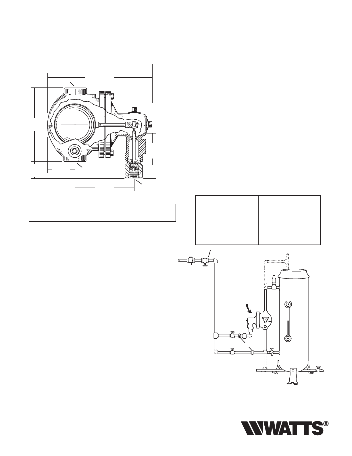
Watts No. 142
Process Boiler Water Feeder
(With Direct Feed Through Float Chamber)
▲
▲
1" N.P.T.
87⁄8" (225mm)
7
⁄8"
4
(124mm)
▲
2
(64mm)
1
⁄2" N.P.T.
1
⁄2"
6"
(152mm)
13⁄8"
(35mm)
1" N.P.T.
3
2
⁄8"
(60mm)
IS-142
Without Strainer- - - - - - - - - - - Type 142
With Strainer- - - - - - - - - - - - - Type 142S
For use on pressing machines and other small process boilers when feed through fl oat chamber is permissible.
Water is fed automatically as needed to maintain the correct
operating level in the boiler.
The entire unit is simple in design and operation, easy to
install and inexpensive to operator.
The simple construction of the feed valve permits quick and
easy cleaning should it become fouled by dirt in the water
supply.
Specifi cations
Connections: Water Feed - 1⁄2" (13mm)
N.P.T. Female
Float Chamber - 1" (25mm)
N.P.T. Female
Pressure: Steam - Max. 100 psi (6.9 bars)
Water - Max. 125 psi (8.6 bars)
Water Pressure must be at least
10 psi (69 kPa) higher than steam
pressure.
Capacity
Diff. between steam Boiler Horse Power
“ATTENTION INSTALLER: After installation, please leave this
Instruction Sheet for occupant’s information.”
and water pressure.
10 8
20 13
30 16
Installation Instructions
Install feeder as illustrated. If boiler tappings for equalizing pipes
“A” and “B” are not available, connect either one or both as
shown by dotted lines. Install with “water line” mark on fl oat
chamber on a level with the middle try-cock, or about halfway
up the gauge glass. Connect water supply line “C”. If a strainer
is used, install it in this line.
Install by-pass “D” so that boiler can be fi lled by hand, if necessary.
All valves should be tight-closing and of good quality. Leaky
valves will fl ood boiler. Blow down fl oat chamber at least once
a week by opening valve “F” and letting water run for a few
minutes.
A shutoff and check valve must be installed in the water supply
line “E”.
Limited Warranty: Watts Regulator Co. (the “Company”) warrants each product to be free from defects in material
and workmanship under normal usage for a period of one year from the date of original shipment. In the event of such
defects within the warranty period, the Company will, at its option, replace or recondition the product without charge.
THE WARRANTY SET FORTH HEREIN IS GIVEN EXPRESSLY AND IS THE ONLY WARRANTY GIVEN BY THE COMPANY
WITH RESPECT TO THE PRODUCT. THE COMPANY MAKES NO OTHER WARRANTIES, EXPRESS OR IMPLIED. THE
COMPANY HEREBY SPECIFICALLY DISCLAIMS ALL OTHER WARRANTIES, EXPRESS OR IMPLIED, INCLUDING
BUT NOT LIMITED TO THE IMPLIED WARRANTIES OF MERCHANTABILITY AND FITNESS FOR A PARTICULAR
PURPOSE.
The remedy described in the first paragraph of this warranty shall constitute the sole and exclusive remedy for breach
of warranty, and the Company shall not be responsible for any incidental, special or consequential damages, including
without limitation, lost profits or the cost of repairing or replacing other property which is damaged if this product does
not work properly, other costs resulting from labor charges, delays, vandalism, negligence, fouling caused by foreign
material, damage from adverse water conditions, chemical, or any other circumstances over which the Company has
no control. This warranty shall be invalidated by any abuse, misuse, misapplication, improper installation or improper
maintenance or alteration of the product.
Some States do not allow limitations on how long an implied warranty lasts, and some States do not allow the exclusion or limitation of incidental or consequential damages. Therefore the above limitations may not apply to you. This
Limited Warranty gives you specific legal rights, and you may have other rights that vary from State to State. You
should consult applicable state laws to determine your rights. SO FAR AS IS CONSISTENT WITH APPLICABLE STATE
LAW, ANY IMPLIED WARRANTIES THAT MAY NOT BE DISCLAIMED, INCLUDING THE IMPLIED WARRANTIES OF
MERCHANTABILITY AND FITNESS FOR A PARTICULAR PURPOSE, ARE LIMITED IN DURATION TO ONE YEAR FROM
THE DATE OF ORIGINAL SHIPMENT.
40 18
50 19
Check Valve Shut-Off
E
Dotted lines indicate
method of installing
when tappings in boiler
shown in illustration are
not available
Watts type 142
C
D
union
Boiler
A
B
F
Page 2
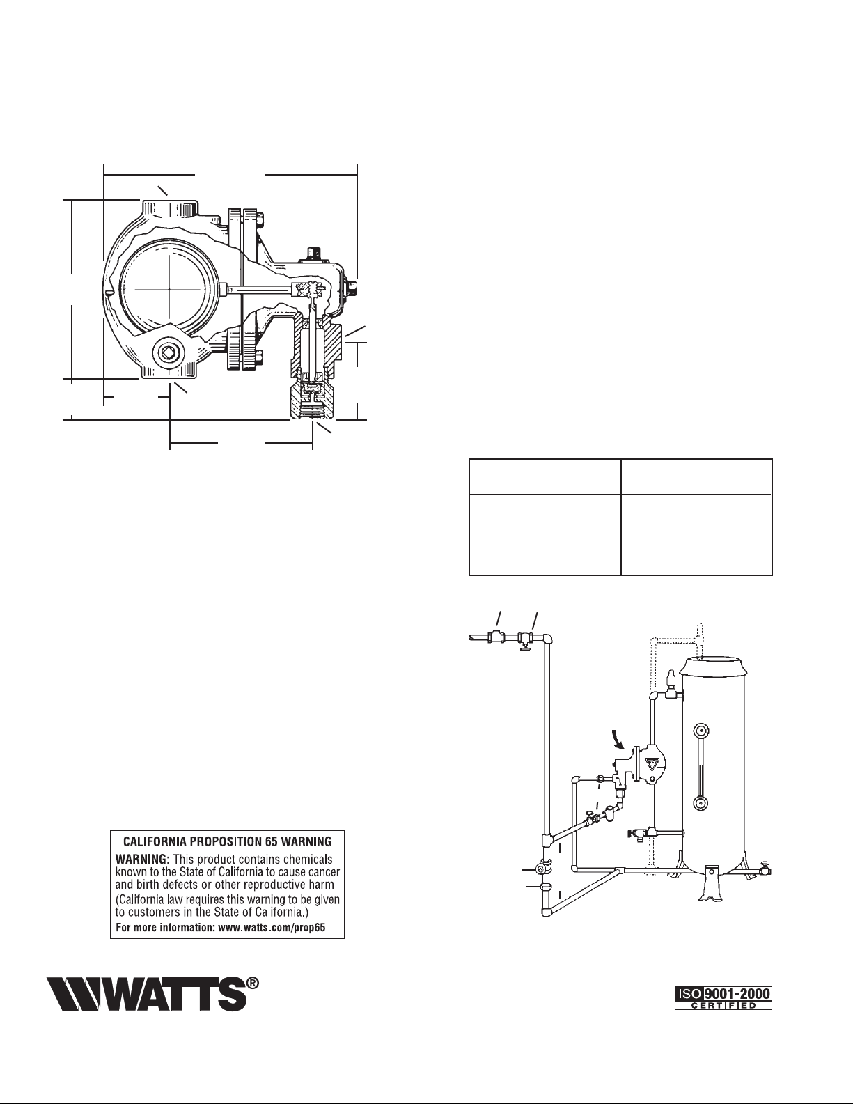
Watts No. 144
Process Boiler Water Feeder
(With External Water Feed Connections)
1" N.P.T.
6"
(152mm)
3
2
13⁄8"
(35mm)
⁄8"
(60mm)
Installation Instructions
Install feeder as illustrated. If boiler tappings for equalizing pipes “A”
and “B” are not available, connect either one or both as shown by
dotted lines.
Install with “water line” mark on fl oat chamber on a level with the
middle try-cock, or about halfway up the gauge glass.
Connect water supply line “C”. If a strainer is used, install it in this
line. Connect feed line “D” from valve to bottom of boiler.
Install by-pass “E” so that boiler can be fi lled by hand if necessary.
All valves should be tight-closing and of good quality. Leaky valves
will fl ood boiler.
Blow down fl oat chamber at least once a week by opening valve “F”
and letting water run for a few minutes.
A shutoff and check valve must be installed in the water supply line
“G”.
▲
▲
1" N.P.T.
87⁄8" (225mm)
7
⁄8"
4
(124mm)
▲
▲
2
(64mm)
1
⁄2" N.P.T.
1
⁄2" NPT
1
⁄2"
Without Strainer- - - - - - - - - - - Type 144
With Strainer- - - - - - - - - - - - - Type 144S
For pressing machine and other small process boilers.
Water is automatically supplied to the boiler as needed
to maintain boiler water at the correct working level.
Feed valve is fl oat-operated and simply constructed.
Can be easily cleaned if fouled by dirt in the water supply.
Water is fed to the boiler through an independent connection to the bottom of the boiler.
Specifi cations
CONNECTIONS: Water Feed - 1⁄2" (13mm)
PRESSURE: Steam - Max. 100 psi (6.9 bars)
N.P.T. Female
Float Chamber - 1" (25MM)
N.P.T. Female
Water - Max. 125 psi (8.6 bars)
Water Pressure must be at least
10 psi (69 kPa) higher than steam
pressure.
Capacity
Diff. between steam Boiler Horse Power
and water pressure.
10 8
20 13
30 16
40 18
50 19
Check Valve Shut-Off
Dotted lines indicate
method of installing
G
when tappings in boiler
shown in illustration are
not available
Watts type 144
Boiler
union
D
B
C
F
Valve
By Pass
E
Water Safety & Flow Control Products
Union
USA: 815 Chestnut St., No. Andover, MA 01845-6098; www.watts.com
Canada: 5435 North Service Rd., Burlington, ONT. L7L 5H7; www.wattscanada.ca
IS-142 0829 EDP# 1910214 © Watts, 2008
 Loading...