

Page 1
Technical Bulletin
3
4
1
2
5
6
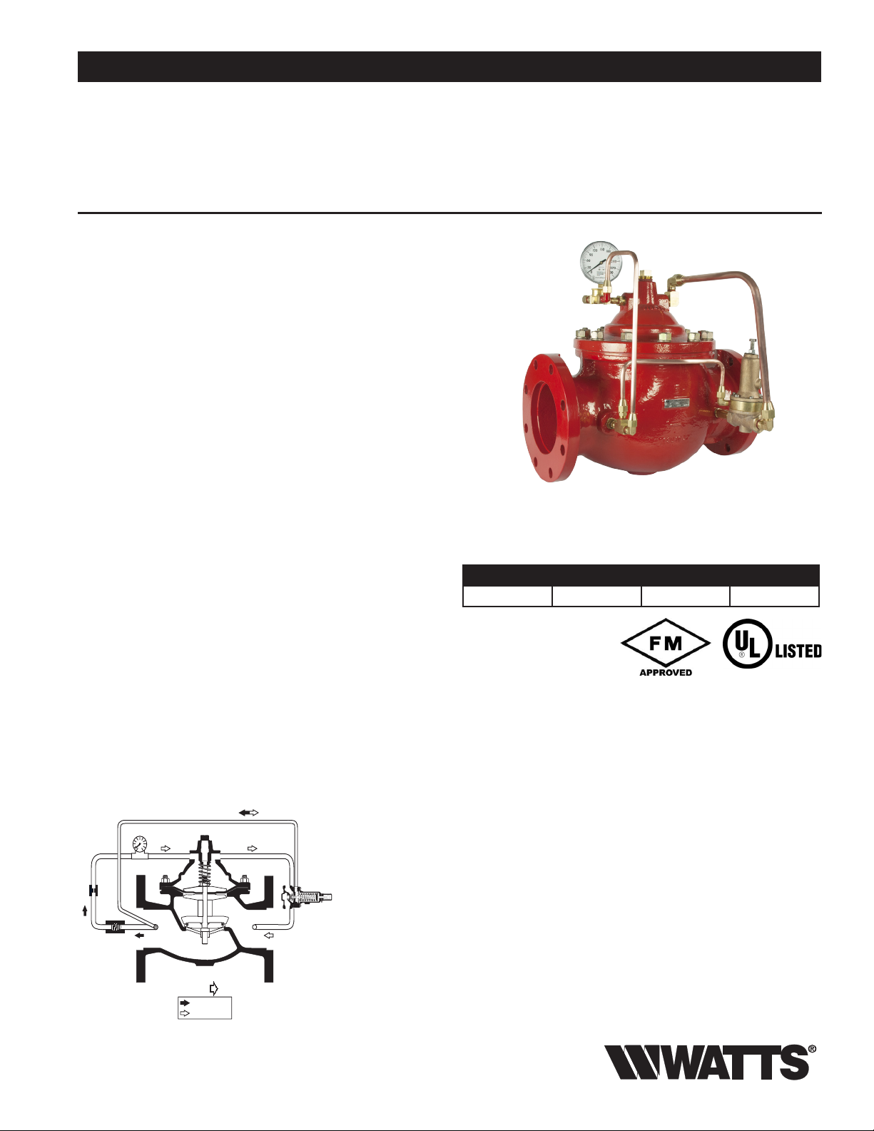
CLOSES VALVE
OPENS VALVE
FLOW
ES-ACV-116FM
Job Name
Job Location
Engineer
Approval
–––––––––––––––––––––––––––––––––––––––––––
–––––––––––––––––––––––––––––––––––––––––
–––––––––––––––––––––––––––––––––––––––––––––
–––––––––––––––––––––––––––––––––––––––––––––
Series 116FM Globe
Fire Pump Relief Valve
Function
Automatically maintains a constant pressure in the fire protection
system by relieving excess pressure.
Features
The WATTS ACV 116FM (Globe) Relief Valve meets all requirements for UL listed, FM Approved fire protection service. The
design and features incorporated in the WATTS ACV Valves
assure accurate control, dependable performance, and long life.
Models
Model 116FM: Globe Pattern Single Chamber Relief Valve
Also Available:
Model 1116FM: Angle Pattern Single Chamber Relief Valve
Materials
Body & Cover: Ductile Iron ASTM A536
Seat (Trim): Stainless Steel CF8M - Xylan Coated
Internals: Stainless Steel S30400 or Ductile Iron
ASTM A536 Fusion Bonded Epoxy
Coated
Stem: Stainless Steel S30400 - Xylan Coated
Spring: Stainless Steel AISI S30200
Elastomers: Buna-N
Control Tubing: Copper
Fittings: Brass
Pressure Relief
Control Body:
Bronze
Contractor
Approval
Contractor’s P.O. No.
Representative
––––––––––––––––––––––––––––––––––––––––––––
–––––––––––––––––––––––––––––––––––––––––––––
––––––––––––––––––––––––––––––––––
––––––––––––––––––––––––––––––––––––––––
116FM Globe
Valve Sizes Available in Angle and Globe
3” 4” 6” 8”
UL UL/FM UL/FM UL/FM
Sizes / Approvals
20 - 175 PSI Relief Service
100-300 PSI Relief Service
ANSI End Connections 150, 300, and 300 x 150
Operation
The WATTS ACV Model 116FM PRESSURE RELIEF VALVE
is controlled by a Pressure Relief Control. The Pressure Relief
Control is normally closed, held closed by an adjustable spring
setting to maintain a constant inlet pressure to the main valve.
When upstream pressure increases above the relief set-point,
the Relief Control throttles open, increasing flow through the
control tubing. Pressure is decreased in the main valve cover
chamber, causing the main valve to modulate towards open,
relieving excess upstream pressure. The desired system pressure is maintained.
Components
Watts product specifications in U.S. customary units and metric are approximate and are provided for reference only. For precise measurements,
please contact Watts Technical Service. Watts reserves the right to change or modify product design, construction, specifications, or materials without prior notice and without incurring any obligation to make such changes and modifications on Watts products previously or subsequently sold.
1 - Main Valve
2 - PV20C Relief Control
3 - Pressure Gauge
4 - Fixed Orifice
5 - Check Valve
6 - Flo-Clean Strainer
As the upstream pressure decreases below the relief set-point,
the Relief Control throttles closed, restricting flow through the
control tubing. Pressure is increased in the main valve cover
chamber, causing the main valve to modulate towards closed,
maintaining the desired upstream pressure. Should upstream
pressure drop below and remain below the set-point, the main
valve closes drip tight.
Page 2
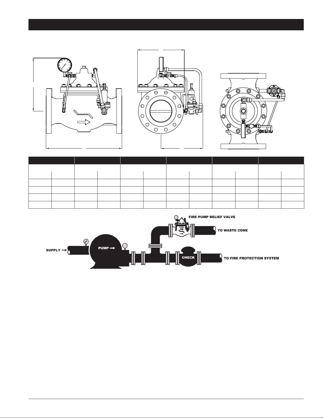
VALVE SIZE
INCH - MM
3 80
6 150
A
150
300
B
C
D
7.875
13.2221.00
12.00
20.00
13.25
10.125
15.00
9.75
11.50
4 100
8 200
9.97
16.00
25.38
15.63
26.38
15.00
10.50
18.50
10.00
13.00
116FM (Globe) - Pressure Relief Valve
DIMENSIONS - ACV 116FM (Globe)
150
120
180
90
210
60
240
270
30
0
300
B
INLET
OUTLET
C
X
WATTS
ACV
XX
A
D
Valve Size 150 Outlet 300 Outlet
A A B C D
in. mm in. mm in. mm in. mm in. mm in. mm
3 80 12 305 131⁄
4 100 15 381 155⁄
4
8
6 150 20 508 21 533 15 381 131⁄
8 800 253⁄
Installation and Start-up
Start-up of an Automatic Control Valve requires following proper procedures. Time must be allowed for the valve to react
to adjustments and the system to stabilize. The objective is to bring the valve into service in a controlled manner to protect
the system from damaging overpressure.
8
645 263⁄
8
337 101⁄
397 101⁄
670 181⁄
8
2
2
257 77⁄
267 915⁄
8
16
4
470 16 406 13 330
200 93⁄
4
248
252 10 254
337 111⁄
2
292
NOTICE: Avoid mounting valves in a vertical discharge postion (valve stem horizontal or cover pointed sideways.) Valves mounted in
this position may not perform as tested and approved.
• Clear the line of slag and other debris.
• Install the valve so that the FLOW ARROW marked on the valve body matches the flow through the line.
• Install pressure gauge (supplied) in the fitting on valve tubing.
1. Turn the Relief Control adjustment screw counterclockwise (out). This lowers the initial relief set-point, allowing the set-point to be
increased to the desired setting.
2. Loosen a tube fitting at a high point on the valve. This allows the cover to vent trapped air during initial filling of the valve.
3. Start the pump to supply fluid/pressure to the valve.
4. Tighten the tubing when all air is vented from the cover as indicated by continual flow of fluid.
NOTICE: THE RELIEF SET-POINT SHOULD BE LOWER THAN DESIRED AT THIS TIME.
5. Turn the Relief Control adjustment screw clockwise (in) slowly, allowing time for the pressure to gradually increase to the desired
set-point.
USA: • Tel. (713) 943-0688 • (713) 944-9445 • www.watts.com
Page 3

116FM (Globe) - Pressure Relief Valve
Cover
Cover bearing
Cover chamber
Spring
Diaphragm
Stem
Spacer
Retainer
Quad seal
retainer plate
Seat
Seat O-ring
Body
F100 Globe
Maintenance
The basic valve normally requires a minimum of maintenance, due
to a packless construction and no required lubrication. However,
it is suggested that a periodic inspection schedule be established
to determine how the fluid is affecting the efficiency of the valve.
Fluid velocity as well as any substance entrained in the fluid, such
as dissolved minerals and/or suspended particles, vary between
installations. In areas subject to freezing, remove the body cover
drain plugs for winter drain-down.
NOTICE: The following method will determine if there is a damaged diaphragm without removing the valve cover. Put pressure into the valve and close all control lines to the valve cover
chamber.Remove a fitting on the valve cover. If there is a continuous flow out of the cover chamber through this opening, the
diaphragm is damaged or the diaphragm assembly on the stem
is loose. CAUTION: The valve will be wide open during this procedure.Omit if the fully open valve could result in system damage.
Stem nut
Diaphragm
washer
Stem O-ring
Quad seal
Drain plug
(alum steel valve only)
Disassembly/Assembly
Inspection or maintenance can be accomplished without removal
from the line.
To replace the diaphragm and/or the quad ring:
1. Remove fitting nuts where necessary to release the valve
cover from the controls or control lines.
2. Remove the cover and spring.
3. Remove the diaphragm and stem assembly, taking care not
to damage the diaphragm when removing over studs.
4. With the assembly removed, examine the diaphragm and
quad ring for wear or damage. Do not disassemble unless
replacement is indicated.
5. To replace the diaphragm, quad ring and/or stem O-ring,
hold the stem in a vise or with wrench on the flats at the
bottom end of the stem. Remove the nuts.
6. Remove the diaphragm washer, diaphragm, etc., in the
proper sequence.
7. Check all surfaces, seat, O-ring grooves and diaphragm
clamping surfaces for damage and/or foreign particles.
8. To reassemble, reverse the order of disassembly. Tighten
stem nuts securely to ensure proper clamping of the diaphragm. To assure positive and even clamping of the diaphragm between the body and the cover, gradually tighten
the cover nuts diametrically opposite each other.
USA: • Tel. (713) 943-0688 • (713) 944-9445 • www.watts.com
Page 4

116FM (Globe) - Pressure Relief Valve
Maximum continuous flow based on velocity of 20 ft. per second.
M
The C
The fac
C
Q (Flow) = C
V
∆ P ∆ P (Pressure Drop) = (Q/C
V
)2
Flow Data - F100 (Globe)
3 4 6 8
Flow Rate GPM (Water) 460 800 1800 3100
Maximum Intermittent
Flow Rate GPM (Water)
Cv Factor GPM (Globe) 125 220 460 775
Cv Factor GPM (Angle) 170 280 650 1100
aximum intermittent flow based on velocity of 25 ft. per second.
Factor of a value is the flow rate in US GPM at 60° F that will cause a 1 psi drop in pressure.
V
tors stated are based upon a fully open valve.
V factor ca n be used in the following equations to determine Flow (Q) and Pressure Drop (∆ P):
Headloss
570 1000 2300 3900
100
80
60
40
20
10
8
6
Pressure Drop (psi)
4
3
2
2 3 4 5 6 789 10 20 40 60 80 100 200 500 1000 2000 5000 10000 20000
Globe
Flow Rate - Gallons per Minute (Water)
4
3
6
8
Valve Cover Chamber Capacity
Valve Size - Inches 3 4 6 8
fluid oz. 10 22 70
U.S. Gal 1-1/4
Valve Travel
Valve Size - Inches 3 4 6 8
Travel - Inches 3/4 1 1-1/2 2
A Watts Water Technologies Company
ES-ACV-116FM 1308 © 2011 Watts
USA:•Tel.(713)943-0688•(713)944-9445•www.watts.com
 Loading...