

Page 1
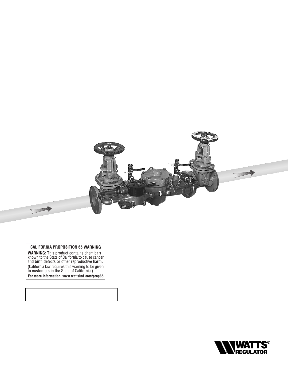
Series 007DCDA
Double Check
Detector Assembly
Sizes: 2" - 3"
• Installation • Service
• Repair Kits • Maintenance
For field testing procedure, send for IS-TK-DL,
IS-TK-9A, IS-TK-99E AND IS-TK-99D.
For other repair kits and service parts, send for
PL-RP-BPD.
RP/IS-007DCDA
Limited Warranty: Watts Regulator Company warrants each product to be free from
defects in material and workmanship under normal usage for a period of one year from
the date of original shipment. In the event of such defects within the warranty period, the
Company will, at its option, replace or recondition the product without charge. This shall
constitute the sole and exclusive remedy for breach of warranty, and the Company shall
not be responsible for any incidental, special or consequential damages, including without limitation, lost profits or the cost of repairing or replacing other property which is
damaged if this product does not work properly, other costs resulting from labor charges,
delays, vandalism, negligence, fouling caused by foreign material, damage from adverse
water conditions, chemical, or any other circumstances over which the Company has no
control. This warranty shall be invalidated by any abuse, misuse, misapplication or
improper installation of the product. THIS WARRANTY IS IN LIEU OF ALL OTHER WAR-
RANTIES, EXPRESS OR IMPLIED, INCLUDING ANY IMPLIED WARRANTIES OF MERCHANTABILITY OR FITNESS FOR A PAR TICULAR PURPOSE.Any implied warranties that
are imposed by law are limited in duration to one year.
Some States do not allow limitations on how long an implied warranty lasts, and some
States do not allow the exclusion or limitation of incidental or consequential damages.
Therefore the above limitations may not apply to you. This Limited Warranty gives you
specific legal rights, and you may have other rights that vary from State to State. You
should consult applicable state laws to determine your rights.
NOTE: For Australia and New Zealand: Pipeline strainers
should be installed between the upstream shutoff valve and the
inlet of the backflow preventer.
Its important that this assembly be tested periodically in compliance with local codes, but at least once per year or more as
service conditions warrant. If installed on a fire sprinkler system, all mechanical checks, such as alarm checks and backflow preventers, should be flow tested and inspected internally
in accordance with NFPA 13 and NFPA 25.
007DCDA Size: 21⁄2"
IMPORT ANT: Inquire with governing authorities
for local installation requirements.
Page 2
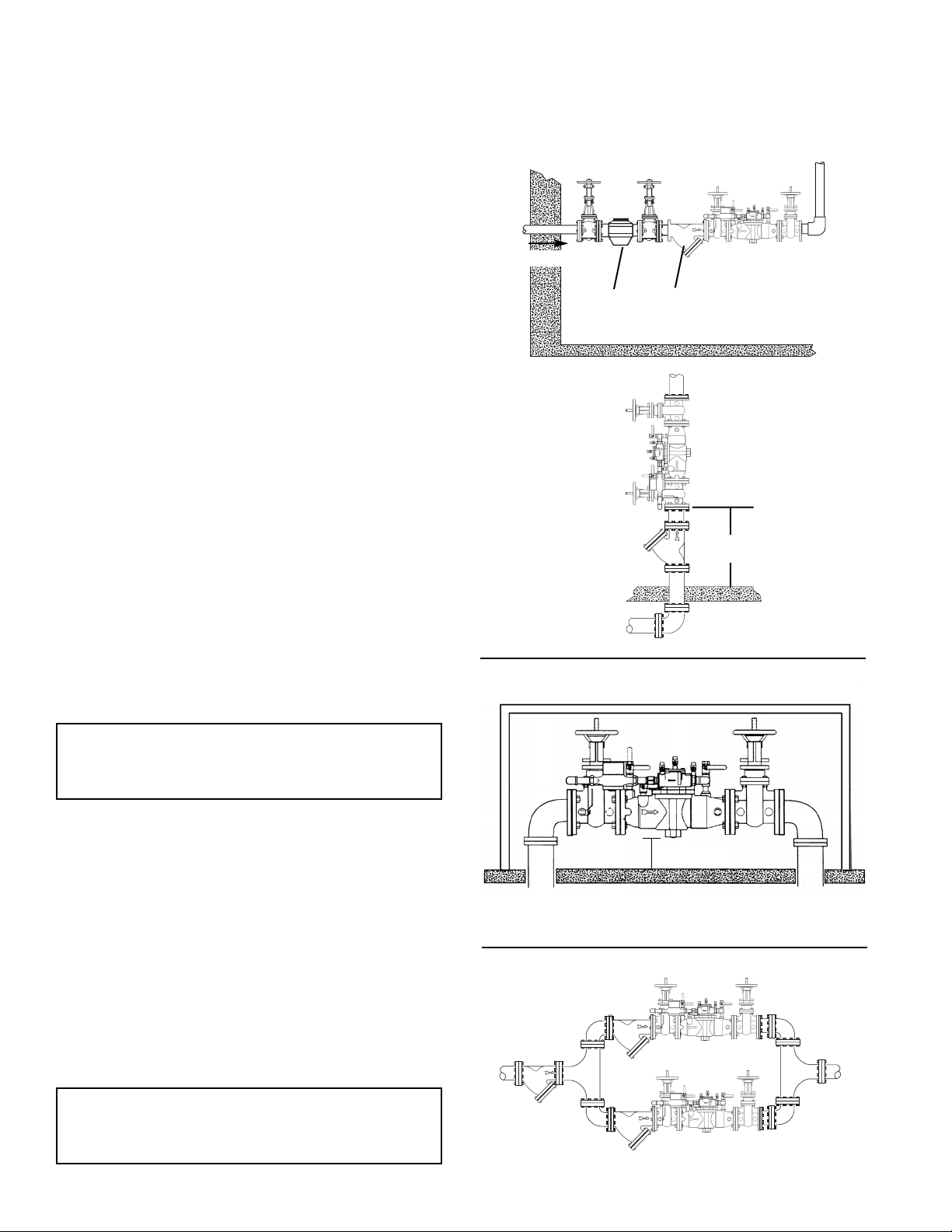
Installation Instructions
2" - 3" 007DCDA
Indoors –
Figure 1
Watts Series 007DCDA may be installed in either a vertical or
horizontal position. Pipe lines should be thoroughly flushed to
remove foreign material before installing the unit. A strainer
should be installed as shown, ahead of backflow preventer to
prevent disc from unnecessary fouling. Install valve in the line
with arrow on valve body pointing in the direction of flow.
For indoor installations, it is important that the valve be easily
accessible to facilitate testing and servicing. Do not install in a
concealed location.
CAUTION: Do not install with strainer when backflow preventer
is used on seldom-used water lines which are called upon during emergencies, such as fire sprinkler lines, etc.
It is important that Series 007DCDA be tested periodically in
compliance with local codes, but at least once a year or more
often depending upon system conditions.
Note Fire Protection System Installations:
The National Fire Protection Agency (NFPA) Guidelines require a
confirming flow test to be conducted whenever a “main line”
valve such as the shutoff valves or a backflow assembly have
been operated. Certified testers of backflow assemblies must
conduct this test. The trim valves of the detector meter bypass
line, on assemblies so equipped, should be shut off during the
confirming flow test. When the test is completed the trim valves
must be retuned to a fully open position.
Outside – Figure 2
In an area where freezing conditions do not occur, Series
007DCDA can be installed outside of a building. The most satisfactory installation is above ground and should be installed in
this manner whenever possible.
In an area where freezing conditions can occur, Series
007DCDA should be installed above ground in an
insulated enclosure.
Parallel – Figure 3
Two or more Series 007DCDA smaller size valves may be piped
in parallel (where approved) to serve a larger supply pipe main.
This type of installation is employed whenever it is vital to maintain a continuous supply of water/where interruptions for testing
and servicing would be unacceptable. It also has the advantage
of providing increased capacity where needed beyond that provided by a single valve and permits testing or servicing of an
individual valve without shutting down the complete line. For
two valve installations the total capacity should equal or exceed
that required by the system.
The quantity of valves used in parallel should be determined by
the engineer’s judgement based on the operating conditions of
a specific installation. (See literature F-FC regarding flow curves)
Annual inspection of all water system safety and control
valves is required and necessary. Regular inspection,
testing and cleaning assures maximum life and proper
product function.
Installation Note:
The flange gasket bolts for the gate valves should be
retightened during installation as the bolts may have
loosened due to storage and shipping.
2
Figure 1
Figure 2
Figure 3
Main
Strainer
Meter
Now available,WattsBox Insulated Enclosures,
for more information, send for literature ES-WB.
WattsBox
12" minimum
refer to local codes
Vertical Flow Up
Watts
2", 2
1
⁄2", 3" 007DCDA
Minimum 12"
Watts
2", 21⁄2", 3" 007DCDA
Strainer
Series 77F-D-FDA
Page 3

Servicing First and
Second Check Valves
2" – 3" 007DCDA
Replacement Parts
2", 2
1
⁄2", 3" 007DCDA
When ordering, specify Ordering Code, Kit number and Valve Size.
1. Remove cover bolts and cover.
2. Remove the retainer from the body bore. The check valve
modules can now be removed from the valve by hand or
with a screwdriver.
3. The check seats are attached to the cage with a bayonet
type locking arrangement. Holding the cage in one hand,
push the seat inward and rotate counterclockwise against
the cage. The seat, spring cage, spring and disc assembly
are now individual components.
4. The disc assembly may now be cleaned and reassemble or
depending on its condition, may be discarded and replaced
with a new assembly from the repair kit. O-rings should be
cleaned or replaced as necessary. For more information,
refer to repair parts price list PL-RP-BPD.
5. Reassemble the Check valve modules. Check modules are
installed in the valve body with the seats facing the valve
inlet. The modules must be securely in place before the
retainer can be replace.
NOTE: No special tools required to service Series 007DCDA.
Cover O-ring
Retainer
Body
EDP NO KIT NO. SIZE
First Check Kit
0887980 RK 007DCDA CK1 2"
0887965 RK 007DCDA CK1 2
1
⁄2", 3"
Kit consists of: Seat, Seat O-ring, Disc assembly, Spring, Spring retainer,
Check Cage and Cover O-ring.
Second Check Kit
0887981 RK 007DCDA CK2 2"
0887966 RK 007DCDA CK2 2
1
⁄2", 3"
Kit consists of: Seat, Seat O-ring, Disc assembly, spring, Spring retainer,
Check cage and Cover O-ring.
First and Second Check Rubber Parts
0887982 RK 007DCDA RT 2"
0887967 RK 007DCDA RT 2
1
⁄2", 3"
Kit consists of: Two seat discs, Two seat O-rings, Two Cover O-rings.
Cover Kit
0887983 RK 007DCDA C 2"
0887980 RK 007DCDA C 2
1
⁄2", 3"
Kit consists of: Cover, Cover O-ring.
Seat Kit
0887984 RK 007DCDA S1 2"
0887985 RK 007DCDA S2 2"
0887968 RK 007DCDA S1 2
1
⁄2", 3"
0887969 RK 007DCDA S2 2
1
⁄2", 3"
Kit consists of: Seat, Seat O-ring.
Use only original equipment manufactured parts to protect
the validated warranty.
Seat
Seat
O-ring
Disc.
Assy.
Spring
Retainer
Cage/
Seat
First Check
Service Parts Kit
Second Check
Service Parts Kit
Cover
Check Assemblies
Page 4

Printed in U.S.A.
RP/IS-007DCDA 0325 EDP# 1911335 © Watts Regulator Co., 1998
Watts USA website: www.wattsreg.com
Watts Canada website: www.wattscda.com
Test Procedure
Double Check Valve Assembly
Test Check Valve No. 1
Step 1: Ensure shutoff #1 is open, shutoff #2 is closed.
Step 2: Connect high side hose to test cock #3, low side to
test cock #2 and open both test cock #2 and test
cock #3.
Step 3: Open valve C, then open A to bleed air from the high
side. Close valve A, then open B to bleed low side.
Close valve B.
Step 4: Connect vent hose loosely to test cock #1. Open
valve A to vent air from vent hose. Tighten vent hose
at test cock #1, open test cock #1.
Step 5: Close shutoff #1. Slowly loosen hose at test cock #2
until differential gauge rises to 2 psi and retighten
hose. If the differential reading does not decrease,
record check valves as “tight”.
Test Check Valve No. 2
Step 1: Move the high side hose to test cock #4, low side to
test cock #3 and open both test cock #3 and test
cock #4. Remove vent hose from test cock #1, open
shutoff #1.
Step 2: Open valve C, then open valve A to bleed air from
the high side. Close valve A, then open valve B to
bleed lowside. Close valve B.
Step 3: Connect vent hose loosely to test cock #1. Open
valve A to vent air from the vent hose. Tighten vent
hose at test cock #1, open test cock #1.
Step 4: Close shutoff #1, then slowly loosen hose at test
cock #3 until differential gauge rises to 2 psi and
retighten hose. If the differential reading does not
decrease, record check as tight. Remove all hoses
and restore valve to original working condition.
Note: The assembly will fail both the first and second
check valve tests above, if shutoff #2 leaks excessively.
To test for a leaky #2 shutoff, use the following procedure.
Test for Leaky No. 2 Shutoff
Step 1: Connect the high side to test cock #1, low side to
test cock #4. Open test cock #1 and test cock #4.
Close shutoffs #1 and #2.
Step 2: Close valve C. Open valve A, then open valve B
1
⁄2
turn, loosen hose at test cock #4 to remove air.
Retighten hose.
Step 3: If the differential gauge rises above 0, there is exces-
sive leakage at shutoff #2 and it must be replaced to
test the assembly.
Note: Product informaiton is subject to change without notice and supersedes all previous publications.
Ball Type
Test Valves
(B)
Needle
Valve
(A)
Test Cock
No. 1
Test Cock
No. 2
(C)
Vent Hose
(Color - Blue)
Low Hose
(Color - White or Red)
Test Cock
No. 3
 Loading...