

WattBox WB-800VPS-IPVM-12, WB-800VPS-IPVM-18 Quick Start Manual
™
WB-800VPS-IPVM-12
WB-800VPS-IPVM-18
QUICK START GUIDE
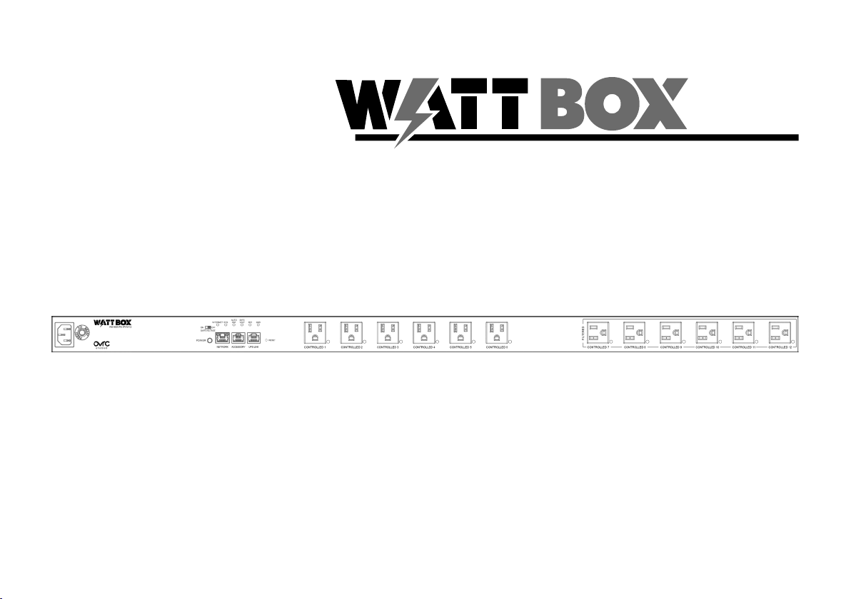
FRONT PANEL
A B C D E F G H I
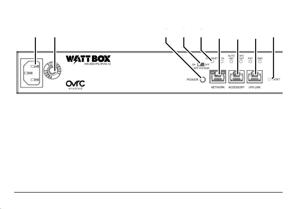
A. Power Inlet: Detachable power cord outlet for 3 prong IEC power cord.
B. Circuit Breaker Reset Button: Press this button to restart the WattBox aer an overload.
C. AC Power switch: Press to manually toggle the outlets on or o. is glows with an amber light when the unit is powered.
D. Safe voltage slider switch: Toggles the “Safe Voltage” feature on and o. On is to the le; o is to the right.
E. Indicator LEDS: See the status of Internet activity, system status, auto reboot, safe voltage, surge protection, and grounding (see
“LED Indicators” on page 9).
F. Network Connection: Connect to the Local Area Nertwork (LAN) for IP control and monitoring.
G. Accessory Port: Not used at this time, but included for future upgrades.
H. UPS Link: For connection to a Wattbox UPS unit.
I. Reset Button: Use a thin tool (paper clip, toothpick) to press this to restart the network card (no settings are changed). Press and
hold 5 seconds to set the power strip to DHCP. Press and hold 10 seconds to reset the power strip to factory default.
Page 2
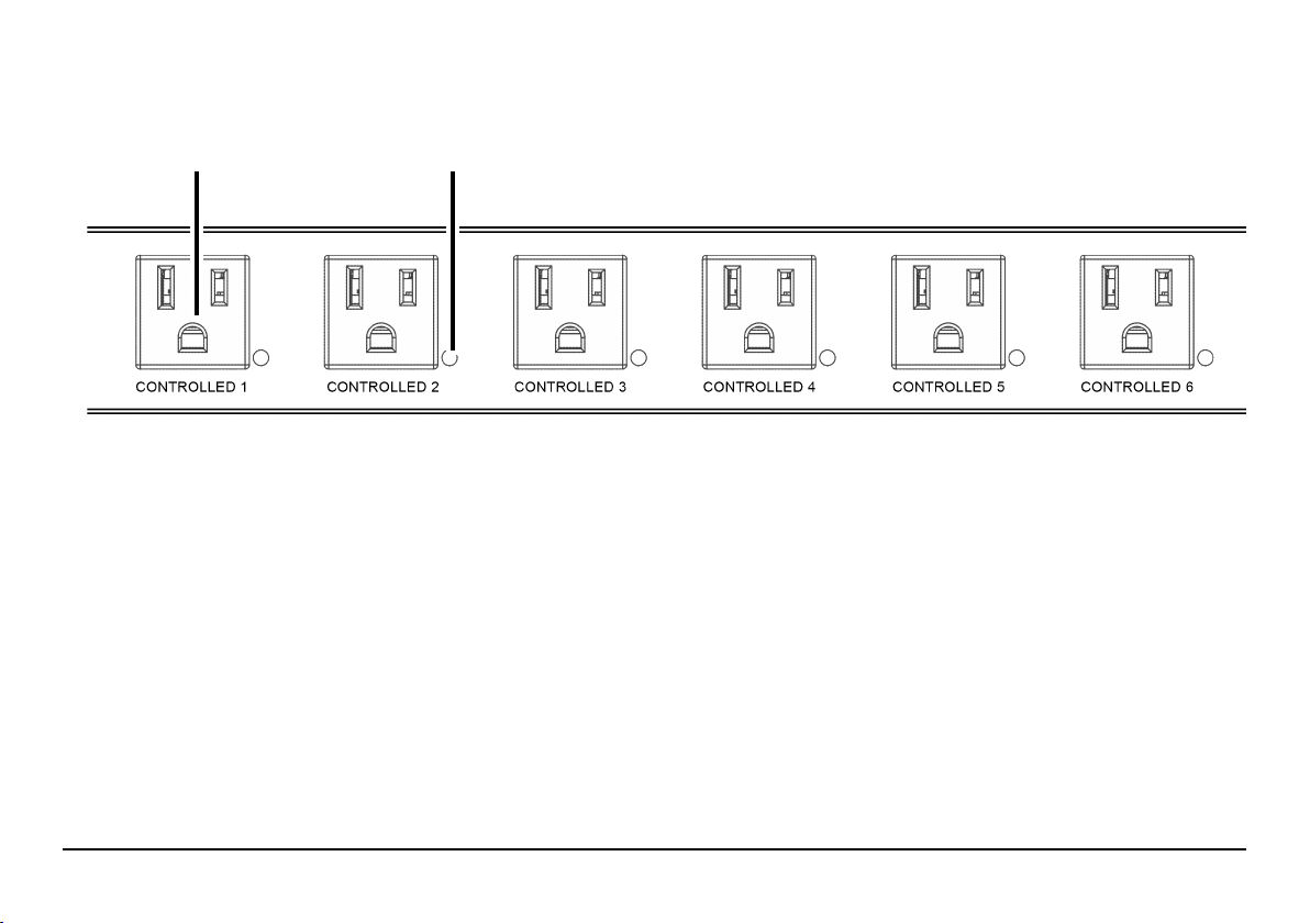
J K
J. Controllable Outlets: All outlets are switchable (IP controlled).
K. Power Indicators: ese illuminate when power to the matching outlet is on.
Page 3
PACKAGE CONTENTS
is package contains:
• Power strip
• Removable power cord
Page 4
• Screws
(2 × for WB-800VPS-IPVM-12,
3 × for WB-800VPS-IPVM-18)
• Nuts
(2 × for WB-800VPS-IPVM-12,
3 × for WB-800VPS-IPVM-18)
• Mounting clips
(2 × for WB-800VPS-IPVM-12,
3 × for WB-800VPS-IPVM-18)
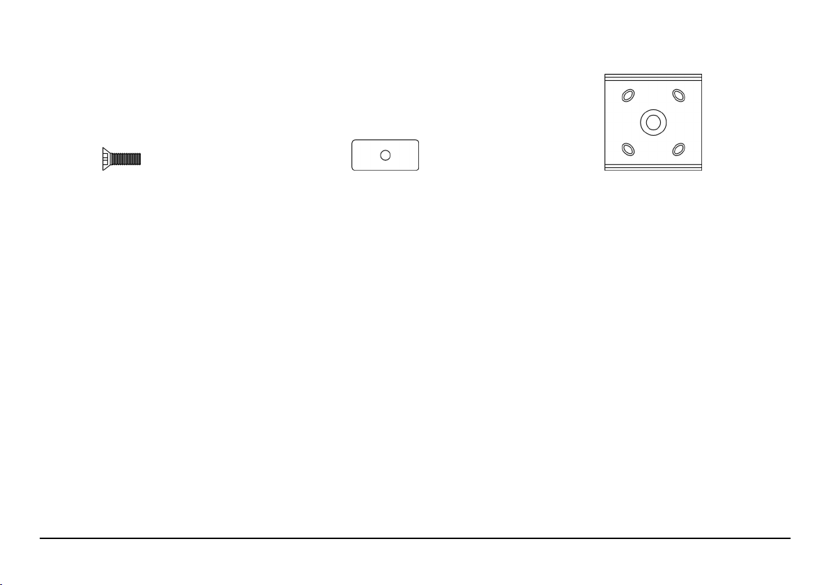
RACK-MOUNT INSTALLATION
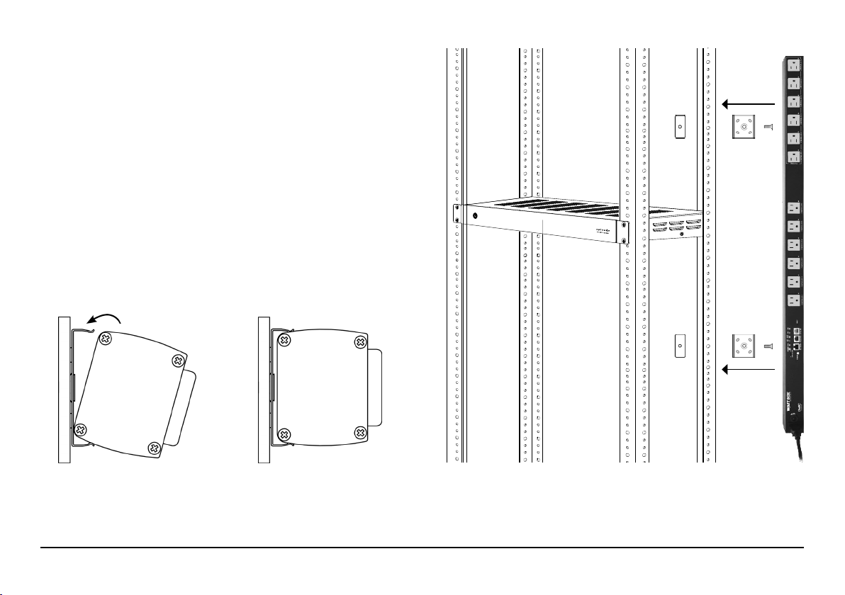
is can be mounted vertically on the outside of one leg of a rack.
Install the Clips
Using the nuts and screws provided, install the mounting brackets
(with the clips oriented as shown at right) on the outside of one
rack rail. Place the clips 4"–6" from each end of the power strip. For
18-outlet units, place the third clip in the center.
Mount the Strip
As shown below, align the power strip with the inside of one edge
of the mounting bracket.
Apply pressure and rotate until the power strip snaps into place.
Page 5
 Loading...