

WattBox WB-200-IW-2 Owner's Manual
OWNERS MANUAL
™
L
I
F
E
T
I
M
E
P
R
O
D
U
C
T
W
A
R
R
A
N
T
Y
SUR
G
E
PRO
T
E
CT
O
R
$
5
,
0
0
0
L
I
F
E
T
I
M
E
P
R
O
D
U
C
T
W
A
R
R
A
N
T
Y
SUR
G
E
PRO
T
E
CT
O
R
$
5
,
0
0
0
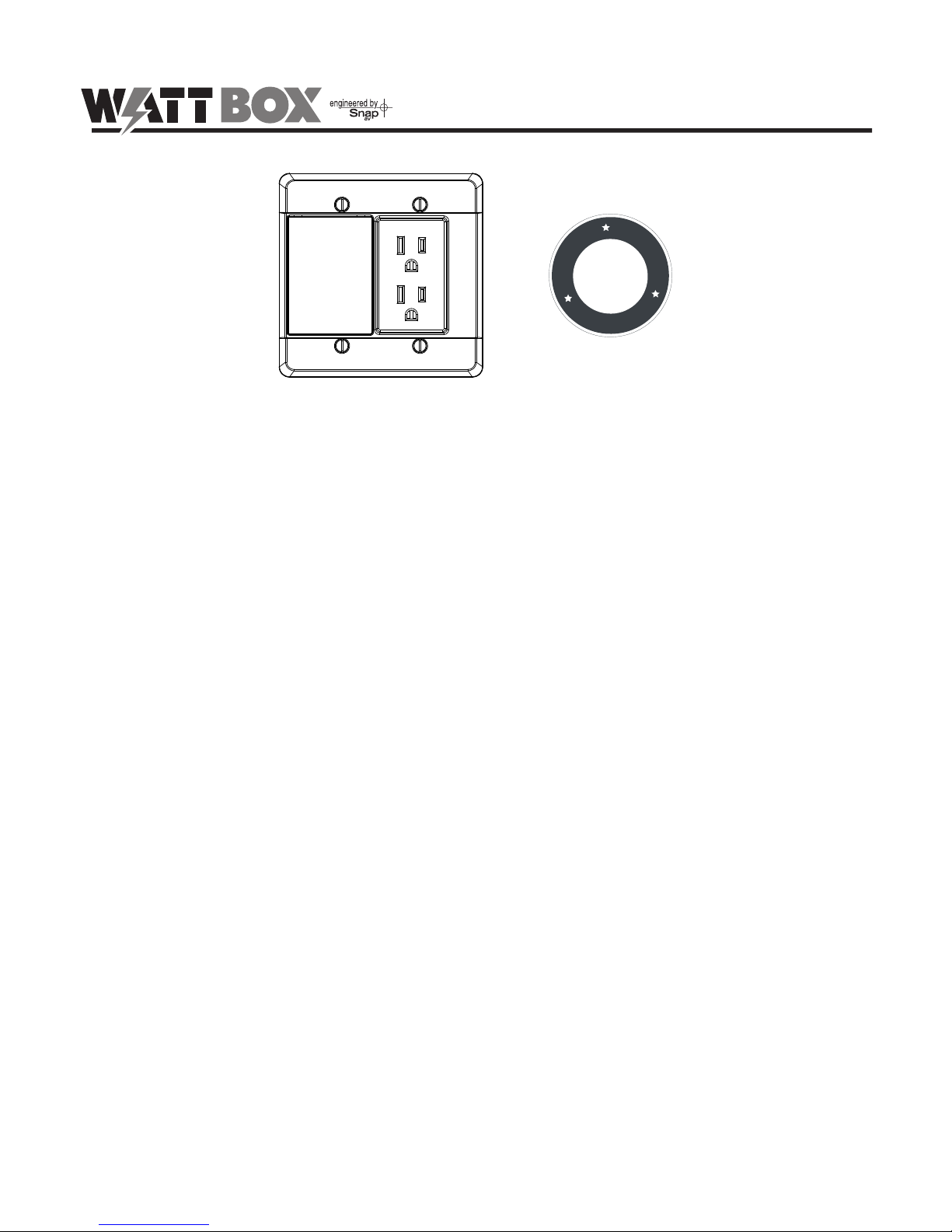
PROTECTED
GROUNDED
WB-200-IW-2
KEY FEATURES
Surge Protection with Fireproof MOVs
Advanced Ceramic MOV technology reduces risk of re from surges.
Surge Disconnect
In the event of a catastrophic surge event, this WattBox™ component will sacrice itself and permanently disconnect AC Power.
Noise Filtration
Eliminates AC noise to improve picture and sound quality.
Child Safety Shutters
Prevents unwanted contact with outlets when exposed.
WELCOME TO WATTBOX™
WattBox™ power products are designed specically to provide customers with advanced protection for their valuable electronics
and Custom Integrators with maximum exibility for installation. Rest assured that WattBox™ products will deliver the protection
and safety for your customers’ needs. This WattBox™ productis UL certied and built with the highest quality components
available, such as Fireproof MOVs.
WattBox™ is the ideal choice for Custom Integrators who demand reliability, safety, and exibility when installing power products
for their valued customers.
pg.2
WB-200-IW-2-WHT Installation and Users Manual
PACKAGE CONTENTS
(1) WB-200-IW-2
(4) Mounting Screws
(3) Wire Nuts
REQUIRED WIRING
We recommend the use of 12/2C or 14/2C IN-DOOR building electrical wire to connect to the WB-200-IW-2. All wiring should be
performed by a licensed electrician . Verify with your electrician that the building electrical wire run to the location of the WB200-IW-2 meets or exceeds 12/2C or 14/2C IN-DOOR.
TOOLS REQUIRED
• Phillips head and at blade screw driver
• Wire-stripper
• Needle Nose Pliers
• Electrical Outlet Tester
IMPORTANT: BEFORE YOU BEGIN!
• Check with your local building jurisdiction as to permit, license or code requirements for installing wire or outlets within a wall.
Some municipalities require an electrical inspection for modication of electrical work. We recommend all modications or
alterations of existing or new electrical work to be inspected by a licensed electrical inspector.
• Install this product to meet National Electrical Code and/or State and Local Building Code requirements for installing electrical building
wire and outlets as a single EXTENSION CIRCUIT, without modication or alteration to the building electrical circuit/wiring system.
Installation Code Compliancy is the responsibility of user and or installer, and not of the Manufacturer or its agents.
• Manufacturer is not liable for damages due to improper installation methods not followed herein or as required by national
electrical or local building code. It is strongly recommended that a qualied professional should install this product. The WB200-IW-2 was designed for New Construction and ts most boxes available. Fitting into Retro boxes is limited, however these
types of boxes can be used if the design of the box is greater than the internal dimensions indicated in the Unit Dimensions
diagram.
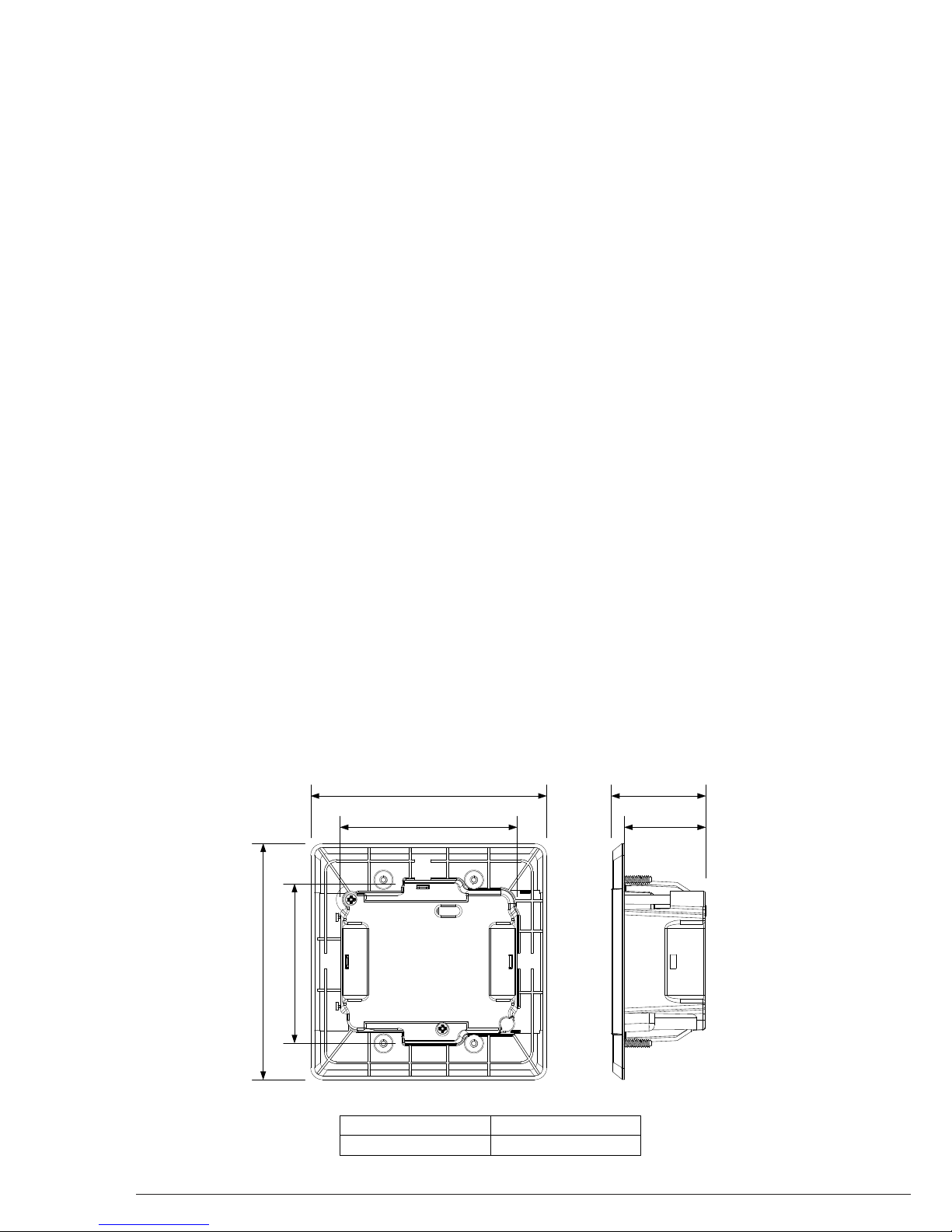
3.2in.
1.6in.3.5in.
4.7in.
4.7in. 2.2in.
External Dimensions
Internal Dimensions
4.7" H x 4.7" W x 2.3" D
3.2" H x 3.5" W x 1.6" D
WB-200-IW-2-WHT Installation and Users Manual
pg.3
© 2012 Wattbox
™
FRONT PANEL
INSTALLATION
1. Grounded Indicator LED
Green: WattBox Power Conditioner is grounded.
Off: Incoming AC outlet is not grounded and requires
inspection by an electrician.
2. Protection Indicator LED
Green: WattBox is powered on and outlets are protected.
Off: WattBox is not powered on, or the Surge Protection
circuitry has engaged, removing power from the outlets.
3. Outlets (Always On)
! Important Note: Before beginning the installation, turn the AC circuit to the location for the WB-200-IW-2 OFF.
Connecting while power is present is not recommended and can cause an unsafe condition.
1. Install a Double Gang outlet box (not included) in the desired location for the WB-200-IW-2.
2. Run a minimum of 14/2C IN-DOOR building electrical wire through the rear opening of the outlet box. Leave about 3 inches
of wire extending out of the box.
3. Verify that the AC circuit to the location is OFF.
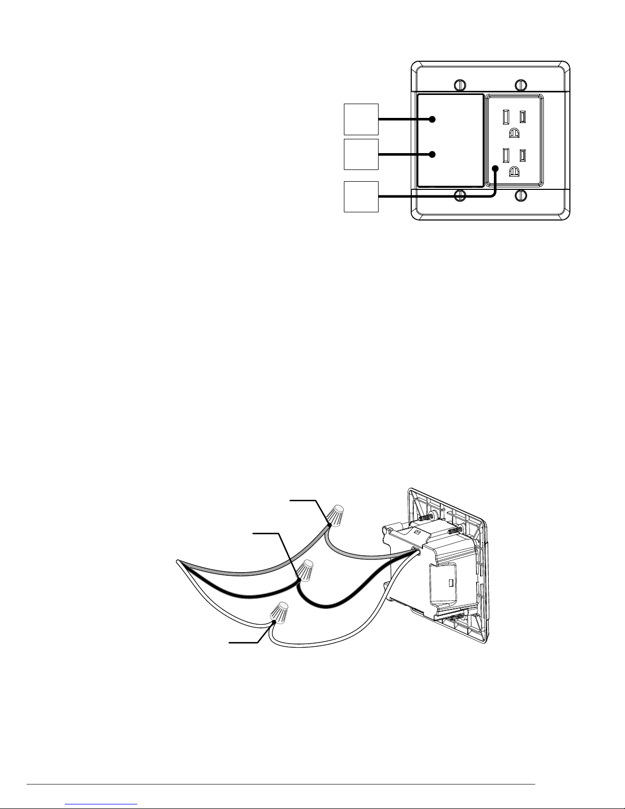
4. Strip 1/4 -inch off each of the three ROMEX® wires and three wires on the rear of the WB-200-IW-2.
5. Using wire nuts, connect the three electrical wires to the WB-200-IW-2.
Green: Ground
Black: Line – Hot
White: Neutral
6. Push excess electrical wire back through the rear opening of the BLUE workbox and make sure to have the wire nuts all the
way into the back.
7. Place the WB-200-IW-2 into the workbox and screw securely into place with the supplied screws.
8. Turn the AC circuit ON; the Grounded and Protected LEDs will illuminate GREEN.
PROTECTED
GROUNDED
1
2
3
Note: This wire may be gray or bare wire on the electrical wires.
WB-200-IW-2
Wire from Wall
Green (Ground)
Black (Line - Hot)
White (Neutral)
 Loading...