

Page 1
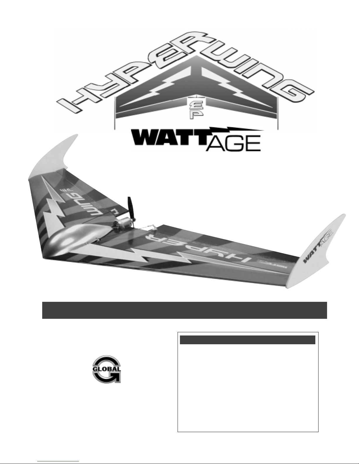
Awesome. That’s what everyone is saying
about the Hyper Wing from WattAge. Flies great
in wind, flies great in the calm, will fly just
about anywhere because of its wide speed
range! And, you’ll get it to the field quick too,
because the Hyper wing is super-easy to finish.
INSTRUCTIONS FOR FINAL ASSEMBLY
The Wattage Hyper Wing 400 EP is distributed
exclusively by Global Hobby Distributors
18480 Bandilier Circle, Fountain Valley, CA 92708
All contents copyright © 2003, Global Hobby
Distributors Version V1.0 May 2003
Kit Product Numbers:
128445 Standard Kit w/Motor & Prop
128446 Deluxe Kit w/Motor, Prop, ESC & Battery
Need help or have any questions? Call us at 1-714-963-0329 or send us an Email at service@globalhobby.net
Specifications:
●
Wing Span: 39.2 Inches
●
Wing Area: 321.5 Square Inches
●
Length: 18 Inches
●
Weight RTF: 13 - 15 Ounces
●
Wing Loading: 5.75 - 7 Ounces Per Square Foot
●
Functions: Ailerons, Elevator (Elevons) & Throttle
●
Power: 380 Direct Drive w/5 x 2.5 Propeller
●
Radio Required: 3Ch or More Micro w/2 Micro Servos
●
ESC Required: 8 Cell 15 Amp Micro
●
Battery Required: 8Cell 800Mah 5/4AAA NiMH
1
Page 2

TABLE OF CONTENTS
Safety Warning ...................................................................................... 2
Introduction ............................................................................................ 3
Section 1: Our Recommendations.......................................... 4
Section 2: Tools and Supplies Required ................................ 5
Section 3: Kit Contents ........................................................... 6
Section 4: Motor Break-In ....................................................... 7
Section 5: Joining the Wing Panels ........................................ 8
Section 6: Motor Installation .................................................. 11
Section 7: Control Systems Installation ................................ 13
Section 8: Final Assembly..................................................... 16
Section 9: Balancing the Hyper Wing 400 EP...................... 19
Section 10: Control Throws................................................... 20
Section 11: Preflight Check & Safety ................................... 20
Section 12: Hand-Launching the Hyper Wing 400 EP ......... 21
Section 13: Replacement Parts List ..................................... 22
Product Evaluation Sheet ................................................................... 23
SAFETY WARNING
This R/C airplane is not a toy! If misused or abused, it can cause serious bodily injury and/or damage to property. Fly only
in open areas and preferably at a dedicated R/C flying site. We suggest having a qualified instructor carefully inspect your
airplane before its first flight. Please carefully read and follow all instructions included with this airplane, your radio control
system and any other components purchased separately.
FOR YOUR INFORMATION
To make your modeling experience totally enjoyable, we recommend that you get experienced, knowledgeable help with assembly and
during your first flights. Your local hobby shop has information about flying clubs in your area whose membership includes qualified
instructors. If there is no hobby shop in your area, we recommend that you contact the AMA at the address below. They will be able to
help you locate a flying field near you.
Academy of Model Aeronautics
5151 East Memorial Drive
Muncie IN 47302-9252
(800) 435-9262
www.modelaircraft.org
OUR GUARANTEE
Wattage guarantees this kit to be free from defects in both material and workmanship at the date of purchase. This does not cover any component
parts damaged by use, misuse or modification. In no case shall Wattage's liability exceed the original cost of the purchased kit.
In that Wattage has no control over the final assembly or material used for final assembly, no liability shall be assumed for any damage resulting from
the use by the user of the final user-assembled product. By the act of using the final user-assembled product, the user accepts all resulting liability.
2
Visit our website at http://watt-age.globalhobby.com or for Customer Service at http://globalservices.globalhobby.com
Page 3

INTRODUCTION
Thank you for purchasing the new Wattage Hyper Wing 400 EP. Before completing the final assembly of your new
airplane, please carefully read through this instruction manual in its entirety. Doing so will ensure your success
the first time around!
WATTAGE HYPER WING 400 EP FEATURES
●
Includes 380 Direct Drive Motor and Matching 5 x 2.5 Nylon Propeller
●
Designed for Great Flight Characteristics and Really Cool Looks
●
Includes Fiberglass Reinforcement Spars for Rigidity
●
Accepts a Wide Range of Power Systems - Stock Direct Drive, Gear Drive or Ducted Fan
●
Includes Complete Hardware Package and Custom Decal Covering Skins
●
Fast and Easy Assembly - Over 30 High-Resolution Digital Photos Guide You
This instruction manual is designed to guide you through the entire assembly process of your new airplane in the least
amount of time possible. Along the way you'll learn how to properly assemble your new airplane and also learn tips
that will help you in the future. We have listed some of our recommendations below. Please read through them before
beginning assembly.
●
Please read through each step before beginning
assembly. You should find the layout very complete
and straightforward. Our goal is to guide you through
assembly without any of the headaches and hassles
that you might expect.
●
Keep a couple of small bowls or jars handy to put the
small parts in after you open the accessory bags.
●
We're all excited to get a new airplane in the air, but
take your time. This will ensure you build a straight,
strong and great flying airplane.
●
There are check boxes next to each procedure. After
you complete a procedure, check off the box. This will
help prevent you from losing your place.
●
Cover your work table with brown paper or a soft cloth,
●
If you come across this symbol ☞, it means that
this is an important point or an assembly hint.
both to protect the table and to protect the parts.
If you should find a part missing or damaged, or have any questions about assembly,
please contact us at the address below:
Global Services
18480 Bandilier Circle
Fountain Valley CA 92708
Phone: (714) 963-0329 Fax: (714) 964-6236 Email: [email protected]
Visit our website at http://globalservices.globalhobby.com
To enable us to better serve your needs, please include your email address with any correspondence you send to us.
Your email address will be added to our Customer Service Database so you will automatically receive free updates
and tech notices for your particular product. You will also receive repair status updates (if applicable) and other
important information about your product as it becomes available.
IMPORTANT INFORMATION ABOUT YOUR EMAIL ADDRESS
Global Hobby Distributors will not disclose the information it collects to outside parties. Global Hobby Distributors does not sell,
trade, or rent your personal information to others . Your privacy is important to us.
Need help or have any questions? Call us at 1-714-963-0329 or send us an Email at service@globalhobby.net
3
Page 4

SECTION 1: OUR RECOMMENDATIONS
This section describes our recommendations to help you in deciding which types of accessories to purchase for your
new Hyper Wing 400 EP. We've also included some information on the different types of power systems you may wish to
experiment with in your Hyper Wing 400 EP. Please read through this entire section very carefully.
✦✦
✦
✦✦
IMPORTANT
sories, it's very important to take the weight of these items into consideration. Remember, the lighter the overall weight of the finished
airplane, the better the airplane will fly.
✦✦
✦
✦✦
When choosing accessories for your Hyper Wing 400 EP, such as servos, ESC, receiver and other related acces-
What Servos Do I Use?
The servos you use should be the lightest available, yet still have an adequate amount of torque. We suggest using servos
that weigh no more than 0.22 ounces and have a torque rating of no less than 10 ounces per square inch. Cirrus CS-6.2
servos or Hitec HS-55 servos would be a perfect choice.
What Radio and Receiver Do I Use?
We recommend using a 3 or more channel radio system that includes an elevon mixing function. If your radio does not
support elevon mixing, you will need to purchase a separate electronic elevon mixer.
The receiver should be as light as possible, preferably 1/2oz. or less. Most four-channel micro receivers would be a good
choice. We personally suggest using either the Cirrus MRX-4 Micro receiver or the Hitec Feather Micro receiver. If you
plan on using the larger, heavier Hitec 555 Micro receiver, we suggest removing the case to reduce the receiver's overall
size and weight. If you do remove the case from your receiver, we strongly suggest wrapping the receiver with heat-shrink
material to protect the internal components.
✦✦
✦
✦✦
IMPORTANT
approximately 1000 feet.
✦✦
✦
✦✦
IMPORTANT
receiver's case to reduce its overall size and weight.
✦✦
✦
✦✦
Please be aware that the Cirrus MRX-4 Micro receiver and the Hitec Feather Micro receiver have a usable range of
✦✦
✦
✦✦
If you use the Hitec Focus III AM radio system, you can use the included receiver, but we suggest removing the
What Electronic Speed Control Do I Use?
The ESC you choose should be capable of handling no less than 10-15 amps continuous current. Again, lighter is better.
Your ESC should weigh no more than 1 ounce including the wiring and switch. We suggest using the Wattage IC-15A
Micro electronic speed control. This ESC is very lightweight and can handle up to 15 amps continuous current.
What Flight Battery Do I Use?
The ideal flight battery is one that provides good performance while keeping the overall weight of the airplane to a
minimum. The lighter the airplane is, the better it's going to perform. The 380 direct drive motor and 5 x 2.5 nylon propeller
are matched to the Hyper Wing 400 EP to provide the overall best flight performance. When combined with an 8 cell flight
battery, this power system draws about 5 - 8 amps.
For the best performance with the stock power system, we suggest using the Wattage 8 cell 800Mah 5/4AAA NiMH flight
battery. This flight battery will provide good overall power and excellent flight time.
Can I Use a Different Power System in My Hyper Wing 400 EP?
While the stock power system with an 8 cell 5/4AAA NiMH flight battery will give the best overall flight performance, you can
try different power systems in your Hyper Wing 400 EP. Listed below are a couple of fun options:
●
For more climb authority, but slower flight speeds, try using the Wattage 370 geared power system with 3.67:1 gear box
and 8 x 6.5 propeller (P/N 145346). The same 8 cell 5/4AAA NiMH flight battery can be used, too.
●
For high flight speeds, but less climb power, try using the Wattage PowerFan 400 EDF system (P/N 131401). Matched
with the Wattage 10 cell 5/4AAA NiMH flight battery (P/N 128539), your Hyper Wing 400 EP will be a speed machine.
●
Who says you even need a motor? The Hyper Wing 400 EP flies great as a non-powered glider. Just assemble it per our
instructions, but don't install the power system or ESC. Use a 270Mah 4 cell receiver battery pack and mount it in the nose,
then balance the airplane the same as you would the powered version.
4
Visit our website at http://watt-age.globalhobby.com or for Customer Service at http://globalservices.globalhobby.com
Page 5
OUR RECOMMENDATIONS, CONTINUED....
Here's a List of What We Used to Finish Our Hyper Wing 400 EP:
QTY. 1 443526 Cirrus MRX-4 Micro Receiver (Neg. Shift, Hitec/Futaba)
Hitec Single Conversion FM RX Crystal
QTY. 2 444035 Cirrus CS-6.2 Micro Servos
QTY. 1 128484 Wattage IC-15A Micro Electronic Speed Control
QTY. 1 128538 Wattage 8 Cell 800Mah 5/4AAA NiMH Flight Battery
QTY. 1 130108 Wattage PF-12 AC/DC Park Flyer Charger
3M 3/4" Wide Clear Plastic Tape - Available at Most Hardware Stores
Note: The Hyper Wing 400 EP uses
elevons for control. If your radio
transmitter does not have elevon mixing
capability, you will need to purchase an
electronic elevon mixer. We suggest the
Wattage Elevon Mixer P/N 128460.
✦✦
✦
✦✦
IMPORTANT
universal connector. The part number listed for the Cirrus MRX-4 receiver is compatible with Hitec and Futaba radio control
systems. This receiver is also available for JR and Airtronics radio control systems. The Wattage IC-15A Micro ESC is compatible
with Futaba, JR, Hitec, Airtronics-Z and others.
When you purchase the Cirrus MRX-4 receiver, you must also purchase a Hitec brand crystal compatible with the receiver. The
crystal must also be on the same frequency as your transmitter. Note that the MRX-4 receiver uses a single conversion FM
Hitec crystal.
✦✦
✦
✦✦
The part number listed for the Cirrus servos is compatible with all radio control systems. This servo uses a
INFORMATION ABOUT COVERING YOUR HYPER WING 400 EP
Your Wattage Hyper Wing 400 EP comes with four self-adhesive decal "skins" that can be used to cover the entire surface of the top
and bottom of your airplane. By using this decal material, the weight of the Hyper Wing 400 EP is kept to a minimum while adding
strength to the structure and making the airplane look good. If you want you can choose to leave your Hyper Wing 400 EP
uncovered, cover it in after-market colored packing tape or cover it using your favorite materials and methods. Keep in mind,
though, that the idea is too keep the airplane as light as possible, yet still be strong and look good.
Included is white plastic reinforcement tape that can be attached to the underside of the leading edge to help prevent damage during
landing. To help save weight, this should only be applied if you will be landing on rough surfaces or if you are using heavier
than recommended flight gear.
SECTION 2: TOOLS AND SUPPLIES REQUIRED
❑ Kwik Bond 5 Minute Epoxy # 887560
❑ Kwik Bond Thick C/A # 887510
❑ Pacer Z-42 Threadlocker # 339162
❑ # 0 & # 1 Phillips Head Screwdrivers
❑ 1.5mm Hex Wrench
❑ Magnum Z-Bend Pliers # 237473
❑ Wire Cutters
❑ Needle Nose Pliers
❑ Adjustable Wrench
❑ Excel Modeling Knife # 692801
❑ Scissors
❑ Ruler
❑ Pencil
❑ Masking Tape
❑ Builder's Triangle
❑ 220 Grit Sandpaper w/Sanding Block
❑ Paper Towels
❑ Rubbing Alcohol
❑ NHP Epoxy Mixing Sticks # 864204
❑ NHP Epoxy Mixing Cups # 864205
❑ K&S 30 Watt Soldering Iron # 598120
❑ Solder
FOR MOTOR BREAK IN YOU WILL NEED:
❑ Emerald Performance Plus Motor Spray # 340186
❑ Trinity Motor Break-In Drops # 840768
❑ Rubber Bands
Need help or have any questions? Call us at 1-714-963-0329 or send us an Email at service@globalhobby.net
5
Page 6

SECTION 3: KIT CONTENTS
We have organized the parts as they come out of the box for easier identification during assembly. Before you begin
assembly, group the parts as we list them below. This will ensure that you have all of the parts before you begin assembly
and it will also help you become familiar with each part.
If you find any parts missing or damaged, please contact us at:
Global Services
18480 Bandilier Circle
Fountain Valley CA 92708
Phone: (714) 963-0329 Fax: (714) 964-6236 Email: [email protected]
AIRFRAME ASSEMBLIES
❑ (1) Right & Left Wing Panels
❑ (2) Ailerons
❑ (2) Wing Tip Fences
❑ (1) Plastic Hatch Cover
❑ (1) Plastic Hand-Launch Fairing
MISCELLANEOUS PARTS
❑ (2) Fiberglass Dowels (Long)
❑ (1) Fiberglass Dowel (Short)
❑ (2) White Plastic Reinforcement Tape (Optional)
❑ (1) Double-Sided Foam Tape
❑ (1) Velcro
❑ (1) White Plastic Mounting Board (2 Parts)
❑ (2) M2 x 10mm Flange-Head Wood Screws
❑ (1) Self-Adhesive Decal "Skins" Set
®
Mounting Material
On the Web
http://globalservices.globalhobby.com
CONTROL SYSTEM ASSEMBLIES
❑ (2) M1.5 x 150mm Threaded Wires
❑ (2) Nylon Control Horns
❑ (2) Nylon Control Horn Backplates
❑ (2) Nylon Clevises
MOTOR ASSEMBLY
❑ (1) 380 Direct Drive Motor
❑ (1) 5 x 2.5 Nylon Propeller
❑ (1) Propeller Adapter w/Washer, Nut & Grub Screw
❑ (1) Fiberglass Motor Plate
❑ (3) Plywood Motor Rails (2 Long & 1 Short)
❑ (2) Nylon Zip-Ties
To convert inches into millimeters: Inches x 25.4 = mm
To convert millimeters into inches: Millimeters / 25.4 = in
✦✦
✦
✦✦
WARNING
glue, or paint that can damage foam. If any of these chemicals comes in contact with the foam parts, the parts will be destroyed and
will not be covered under warranty. Use only epoxy to glue the foam parts together. If you decide to add painted details to the
airplane, use acrylic-based paints and always test the paint on a scrap piece first.
We do not suggest storing your airplane in an extremely hot environment (like the back of your car in direct sunlight) for any length
of time. The extreme heat could cause the foam to melt and/or damage the covering material, and could possibly damage the fragile
components of the radio system, ESC or batteries.
✦✦
✦
✦✦
The Hyper Wing 400 EP is constructed of foam. It is very important that you use no solvents, Cyanoacrylate (C/A)
INFORMATION ABOUT PURCHASING REPLACEMENT PARTS
Wattage stocks a complete line of replacement parts for your Hyper Wing 400 EP. Replacement parts can be purchased through
your local Wattage dealer or directly from us. Please refer to page # 22 for ordering information and a complete replacement
parts list.
6
Visit our website at http://watt-age.globalhobby.com or for Customer Service at http://globalservices.globalhobby.com
Page 7
SECTION 4: MOTOR BREAK-IN
While not "mandatory," we do strongly suggest taking some time to break in the motor. This accomplishes two very
important things: breaking in the motor will maximize its performance and, most importantly, you will be able to verify that
the motor is working properly before installing it into the airplane.
●
To break in the motor, it is recommended that the motor be run for at least 10 minutes without a propeller at a voltage of
less than 5 volts - a 4 cell receiver battery pack works great for this. The low voltage will keep the motor from overheating
while the brushes and bushings seat.
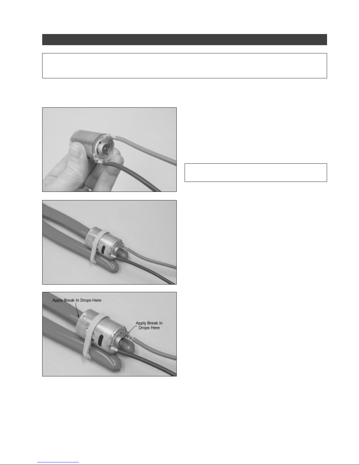
❑ Carefully solder two wires (not included) to the positive
and negative terminals on the back of the motor.
The wires should have a plug on them that is compatible
☞
with the 4 cell battery pack that you will use to break in
the motor.
✦✦
✦
✦✦
IMPORTANT
the positive terminal.
❑ Set the motor between the handles of a pair of pliers
and secure the motor to the handles using several rubber
bands. This is a good way to keep the motor secure for the
break-in procedure.
❑ Before operating the motor, apply a couple of drops of
Break In Drops to the motor bushings. (One at the front and
one at the back of the motor.)
✦✦
✦
✦✦
The terminal with the red dot next to it is
❑ Operate the motor using a fully charged 4 cell battery pack and allow the motor to run for about 8 - 10 minutes. After
8 - 10 minutes, remove the battery pack and spray Motor Spray into the motor (through the two holes in the side of the
motor) to clean the brushes. Apply more Break In Drops to the bushings and run the motor for another 3 - 5 minutes.
❑ After 3 - 5 minutes, remove the battery pack from the motor and spray the brushes clean with Motor Spray. Apply a
couple of drops of Break In Drops to the bushings and wipe the motor clean using a paper towel.
❑ Now that you've completed breaking in the motor, remove the wires from the motor and set it aside for installation later.
Need help or have any questions? Call us at 1-714-963-0329 or send us an Email at [email protected]
7
Page 8
SECTION 5: JOINING THE WING PANELS
YOU'LL NEED THE FOLLOWING PARTS FROM THE KIT:
❑ (1) Right & Left Wing Panels
❑ (2) Ailerons
❑ (2) Fiberglass Dowels (Long)
YOU'LL NEED THE FOLLOWING TOOLS AND SUPPLIES:
❑ Kwik Bond 5 Minute Epoxy
❑ Excel Modeling Knife
❑ Scissors
❑ Ruler
❑ Pencil
❑ Masking Tape
❑ (1) Fiberglass Dowel (Short)
❑ (2) White Plastic Reinforcement Tape (Optional)
❑ (1) Self-Adhesive Decal "Skins" Set
❑ 220 Grit Sandpaper w/Sanding Block
❑ Paper Towels
❑ Rubbing Alcohol
❑ NHP Epoxy Mixing Sticks
❑ NHP Epoxy Mixing Cups
STEP 1: INSTALLING THE LONG FIBERGLASS DOWELS
❑ Using 220 grit sandpaper with a sanding block, lightly sand the top and bottom and the leading and trailing edge of
both wing panels, to remove any mold flashing.
✦✦
✦
✦✦
IMPORTANT
✦✦
✦
✦✦
Be very careful not to distort or otherwise change the airfoil shape of the leading edge or the tip
and root angles.
❑ Using a clean cloth, or even better, a tack rag, wipe down each wing panel to remove any dust and debris.
❑ Working with one wing panel for now, mix a small quantity of 5 minute epoxy and apply a thin layer to the inside of the
precut channel in the bottom of the wing panel.
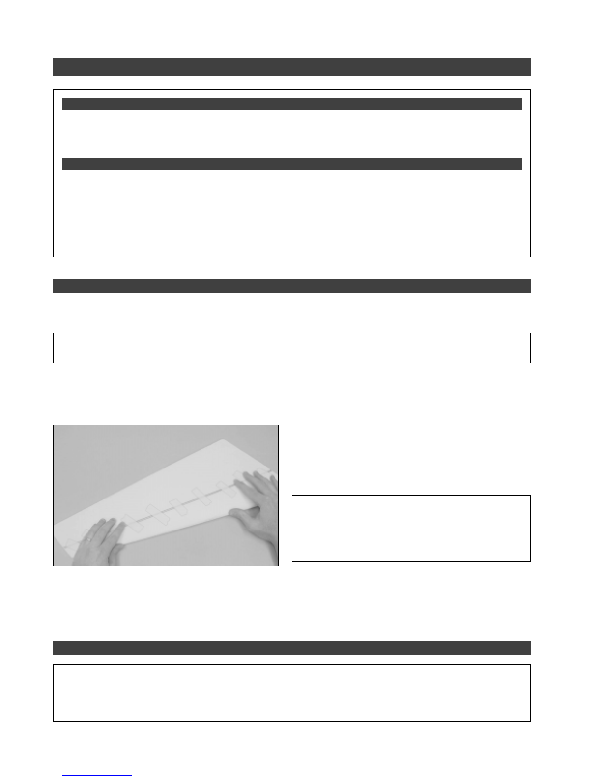
❑ Line up the end of one long fiberglass dowel with the root
end of the wing panel and carefully push the dowel into the
channel. Remove any excess epoxy using a paper towel and
rubbing alcohol, and use pieces of masking tape to hold the
dowel in place until the epoxy sets up.
✦✦
✦
✦✦
IMPORTANT
✦✦
✦
✦✦
When gluing the dowel into place, it's very
important that the dowel be glued securely into the channel
and that the wing panel be perfectly flat during the drying process. We suggest using books or other weights to
hold the wing panel flat.
❑ After the epoxy fully cures, remove the masking tape from the wing panel and double-check that the wing panel is
perfectly flat. It should not be bowed or twisted.
❑ Repeat the previous procedures to install the second long fiberglass dowel into the bottom of the other wing panel.
STEP 2: APPLYING THE WING REINFORCEMENT TAPE
✦✦
✦
✦✦
IMPORTANT
✦✦
✦
✦✦
We provide two strips of white plastic reinforcement tape to reinforce the bottom of the leading edge on
your Hyper Wing 400 EP. Using this reinforcement tape is optional. We suggest using the reinforcement tape if you are
going to be landing your Hyper Wing 400 EP on rough surfaces or if you aren't a very proficient flyer. If you are going to
be landing on soft grass, we don't suggest applying the reinforcement tape. It will just add unnecessary weight.
8
Visit our website at http://watt-age.globalhobby.com or for Customer Service at http://globalservices.globalhobby.com
Page 9
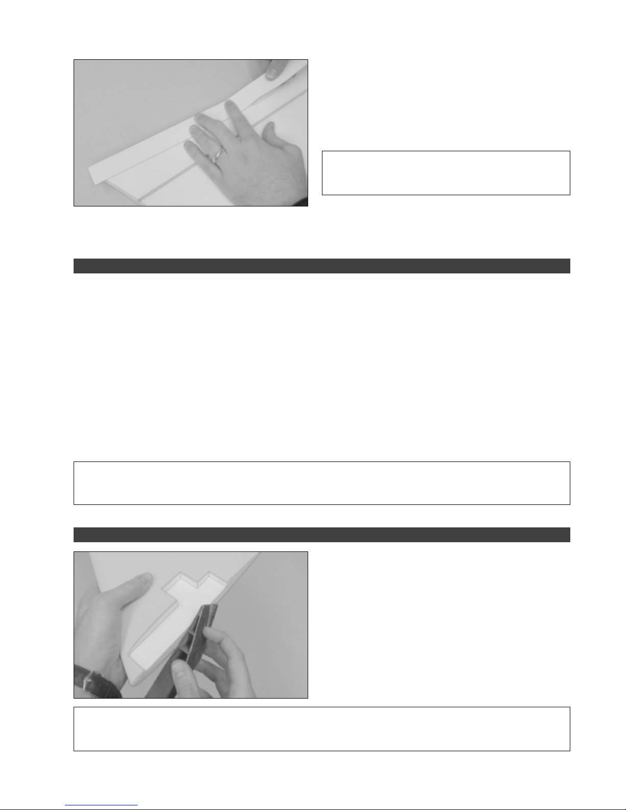
❑ Remove the protective backing from one strip of plastic
reinforcement tape and carefully apply the strip of tape to the
bottom of one wing panel. To align it properly, the front edge
of the reinforcement tape should be parallel to, and just
behind, the molded radius of the leading edge. The
reinforcement tape should be pressed down firmly, too.
✦✦
✦
✦✦
IMPORTANT
tape around the leading edge. The tape is too thick and will
only ruin the leading edge airfoil.
❑ Using a pair of scissors, carefully trim the ends of the reinforcement tape flush with the tips of the wing panel, then
repeat the previous procedures to apply the second strip of reinforcement tape to the bottom of the other wing panel.
STEP 3: COVERING THE WING PANELS
●
If you have decided to apply a covering to your airplane (refer to "Information About Covering Your Hyper Wing 400 EP"
on page # 5), it's easier to do it now than after the wing panels have been glued together. Follow the basic steps outlined
below if you are going to cover your airplane using the included self-adhesive decal "skins".
❑ Remove the protective backing from one bottom skin and carefully apply it to the bottom of one wing panel, making
sure to line up the front edge of the skin parallel to the leading edge of the wing panel. Work slowly and carefully to adhere
the entire skin to the wing panel without introducing any wrinkles, bubbles or creases.
❑ After you have applied the bottom skin, carefully trim away the excess using a modeling knife, being careful not to cut
into the foam.
❑ Repeat the previous procedures to apply one top skin to the top of the wing panel, making sure that the skin wraps
around both the leading and trailing edges and overlaps the bottom of the wing panel about 1/4". After trimming away the
excess, repeat the previous procedures to apply the top and bottom wing skins to the other wing panel.
✦✦
✦
✦✦
Do not attempt to wrap the reinforcement
✦✦
✦
✦✦
IMPORTANT
mind that you don't want to add too much weight with the covering material. You want your airplane to look cool, but you
don't want the covering material to add any unnecessary weight.
STEP 4: JOINING THE WING PANELS
✦✦
✦
✦✦
IMPORTANT
wing should be straight across (flat). You can easily achieve this by gluing the wing panels together upside down on your
work table. It's imperative to double-check that your work table is perfectly flat, too.
✦✦
✦
✦✦
If you are planning on covering your airplane using your favorite materials and methods, just keep in
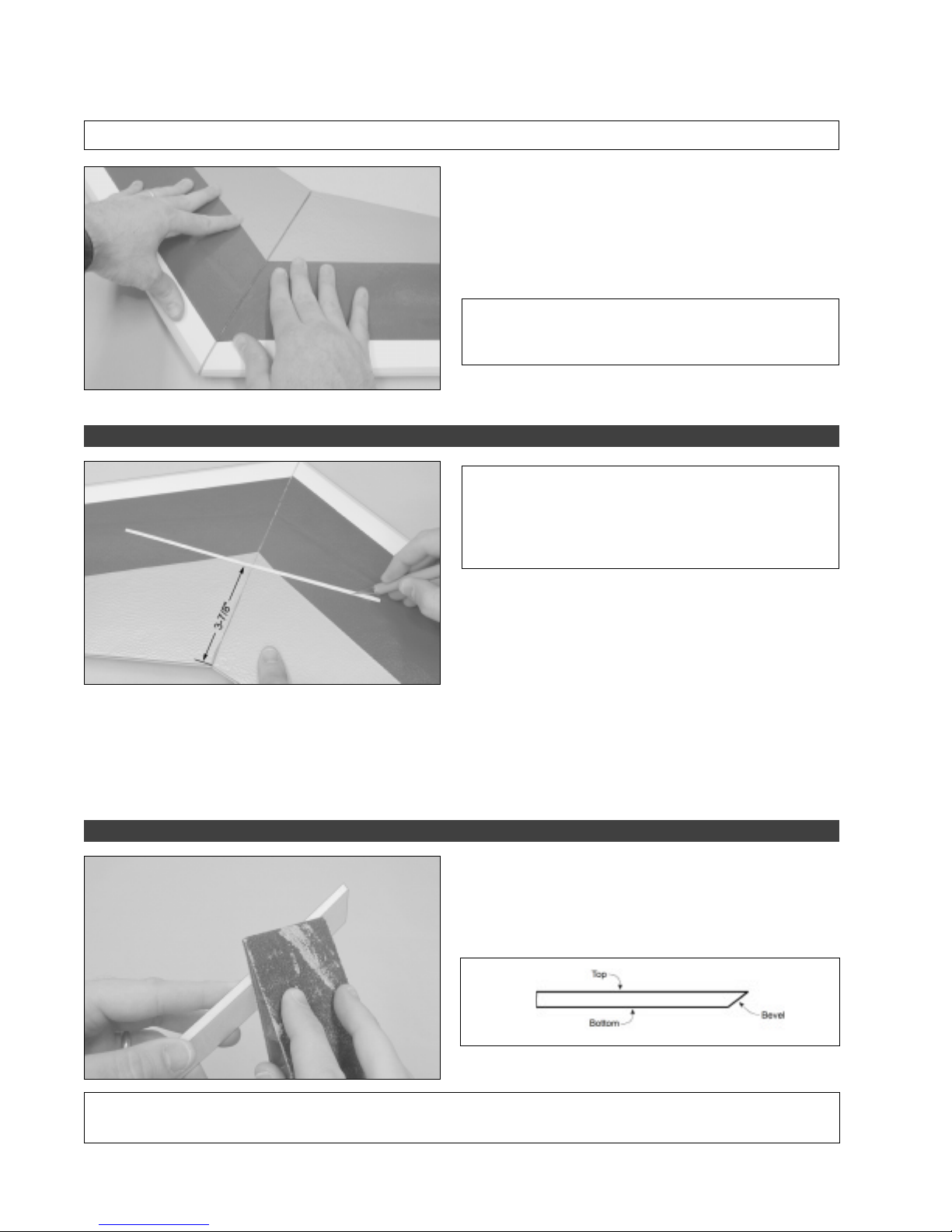
❑ Test-fit the two wing panels together upside down on
your work table. They should fit together with few or no gaps
between the two, and the leading and trailing edges should
line up evenly.
If the wing panels don't fit together properly, carefully
☞
sand the root ends of each wing panel straight using 220 grit
sandpaper with a sanding block, being careful not to alter
the angle of the root ends.
✦✦
✦
✦✦
Before gluing the wing panels together in the next procedure, it's important to know that the top of the
Need help or have any questions? Call us at 1-714-963-0329 or send us an Email at [email protected]
9
Page 10
❑ Mix a generous amount of 5 minute epoxy and carefully apply a thin layer to the root end of both wing panels.
✦✦
✦
✦✦
WARNING
STEP 5: INSTALLING THE SHORT FIBERGLASS DOWEL - OPTIONAL
✦✦
✦
✦✦
For maximum wing strength, make sure to cover the entire surface of each root end.
❑ Fit the wing panels back together and realign them.
Remove any excess epoxy that squeezes out of the joint
using a paper towel and rubbing alcohol, and hold the wing
panels together firmly until the epoxy sets up - about 10
minutes.
✦✦
✦
✦✦
IMPORTANT
important that they be upside down and flat on your work
table.
✦✦
✦
✦✦
IMPORTANT
is optional. This dowel strengthens the wing center section,
but is really only necessary if you're using heavier than
recommended flight equipment or if you are using a more
powerful power system.
✦✦
✦
✦✦
While the wing panels are drying, it's very
✦✦
✦
✦✦
Installation of the short fiberglass dowel
❑ After the epoxy has completely set up, carefully cut a
shallow groove across the bottom of the wing just large
enough to install the short fiberglass dowel. The groove should
be located 3-7/8" in front of the trailing edge of the wing, at
the centerline, and it should be perpendicular to the centerline
of the wing, too.
❑ Test-fit the short fiberglass dowel into the groove. When satisfied with the fit, glue the dowel into the wing, using the
same techniques you used to glue the long fiberglass dowels into each wing panel.
❑ After the epoxy has set up, use a piece of extra covering material to cover the fiberglass dowel. You could also use
extra covering material to cover the center section joint on the bottom of the wing.
STEP 6: HINGING THE AILERONS
❑ Using 220 grit sandpaper with a sanding block, carefully
sand a shallow 45º bevel in the bottom of the leading edge of
one aileron.
✦✦
✦
✦✦
IMPORTANT
tip of the wing, and the top of the aileron (the non-beveled side) should be hinged to the top of the wing.
10
✦✦
✦
✦✦
Before hinging the aileron to the wing, note that the wider portion of the aileron should be toward the
Visit our website at http://watt-age.globalhobby.com or for Customer Service at http://globalservices.globalhobby.com
Page 11
✦✦
✦
✦✦
IMPORTANT
✦✦
✦
✦✦
If you are planning on using a more powerful power system than we recommend, the airplane is
obviously going to fly much faster than intended. We suggest cutting the cord of both ailerons 3/16" shorter to make the
airplane less sensitive at higher speeds. This is not necessary if you're using the stock power system or a gear box.
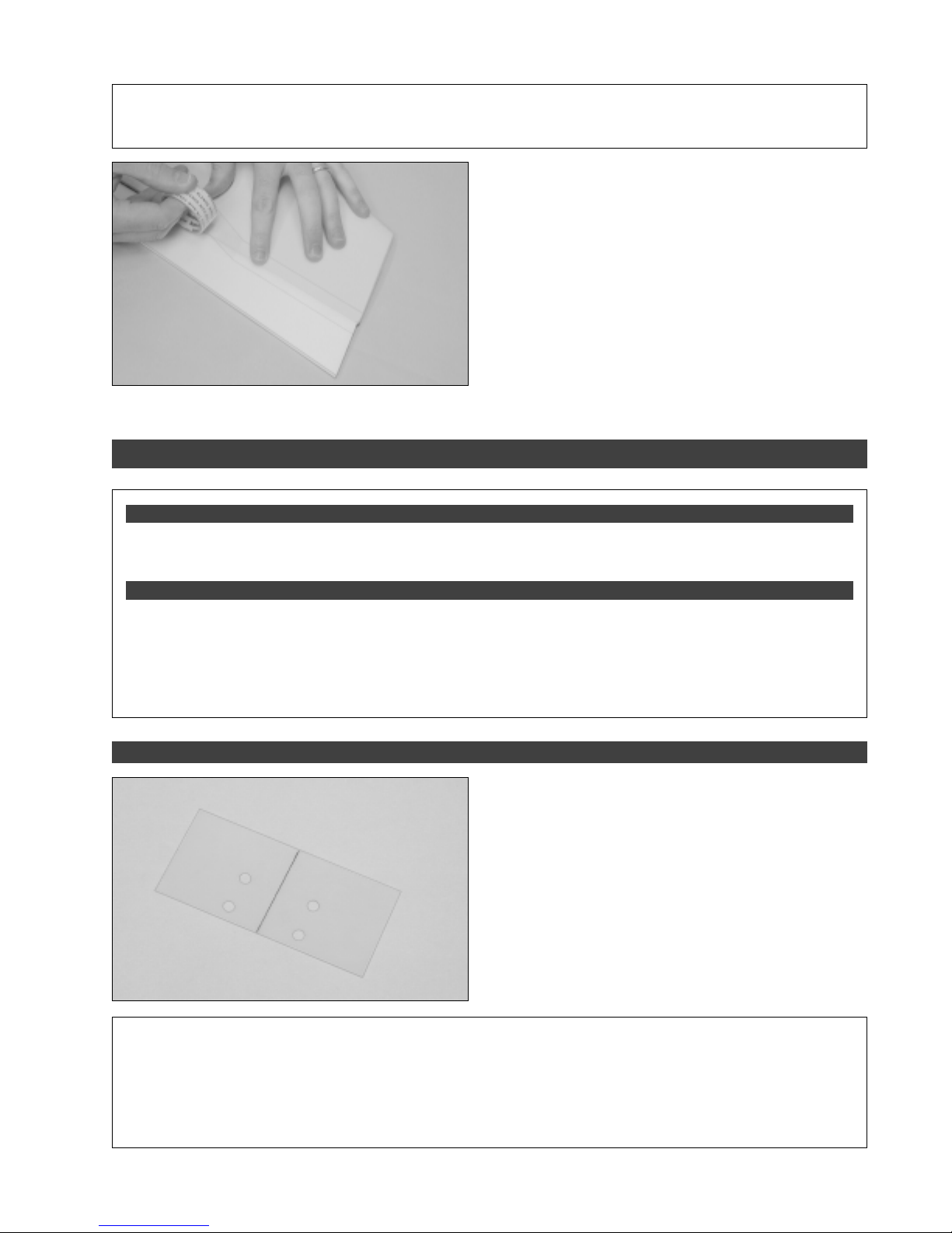
❑ Carefully push the leading edge of the aileron up against
the trailing edge of the wing.
❑ With the tip of the aileron 1/8" in from the tip of the wing
(so it doesn't hit the wing tip fence when it's installed later),
and with no gaps in the hinge line, hinge the aileron to the wing
using a strip of clear plastic tape (not included).
Apply the tape to the top of the parts and double-check
☞
that the wider portion of the aileron is toward the wing tip.
❑ Repeat the previous procedures to hinge the second
aileron to the other half of the wing.
SECTION 6: MOTOR INSTALLATION
YOU'LL NEED THE FOLLOWING PARTS FROM THE KIT:
❑ (1) 380 Direct Drive Motor
❑ (1) Fiberglass Motor Plate
YOU'LL NEED THE FOLLOWING TOOLS AND SUPPLIES:
❑ Kwik Bond 5 Minute Epoxy
❑ Wire Cutters
❑ Excel Modeling Knife
❑ Ruler
❑ Pencil
STEP 1: INSTALLING THE MOTOR PLATE
❑ (3) Plywood Motor Rails (2 Long & 1 Short)
❑ (2) Nylon Zip-Ties
❑ 220 Grit Sandpaper w/Sanding Block
❑ Paper Towels
❑ Rubbing Alcohol
❑ NHP Epoxy Mixing Sticks
❑ NHP Epoxy Mixing Cups
❑ Using a ruler and a pencil, draw a vertical centerline on
one side of the fiberglass motor plate, as shown.
✦✦
✦
✦✦
IMPORTANT
✦✦
✦
✦✦
In the next procedure, you will glue the three plywood motor rails onto the fiberglass motor plate.
These rails will cradle the motor and give a solid base to secure the motor to. These instructions show the motor rails
spaced to fit the stock 380 direct drive motor. If you are using a different motor and/or power system, you will need to
space the rails to fit your particular application. When you glue the two side rails into place, they will partially cover the
predrilled holes in the motor plate. This is okay and is normal. If you need to space the rails out further to suit your
application, they may completely cover the predrilled holes in the motor plate. If this is the case, you will need to redrill
new holes in the motor plate.
Need help or have any questions? Call us at 1-714-963-0329 or send us an Email at [email protected]
11
Page 12
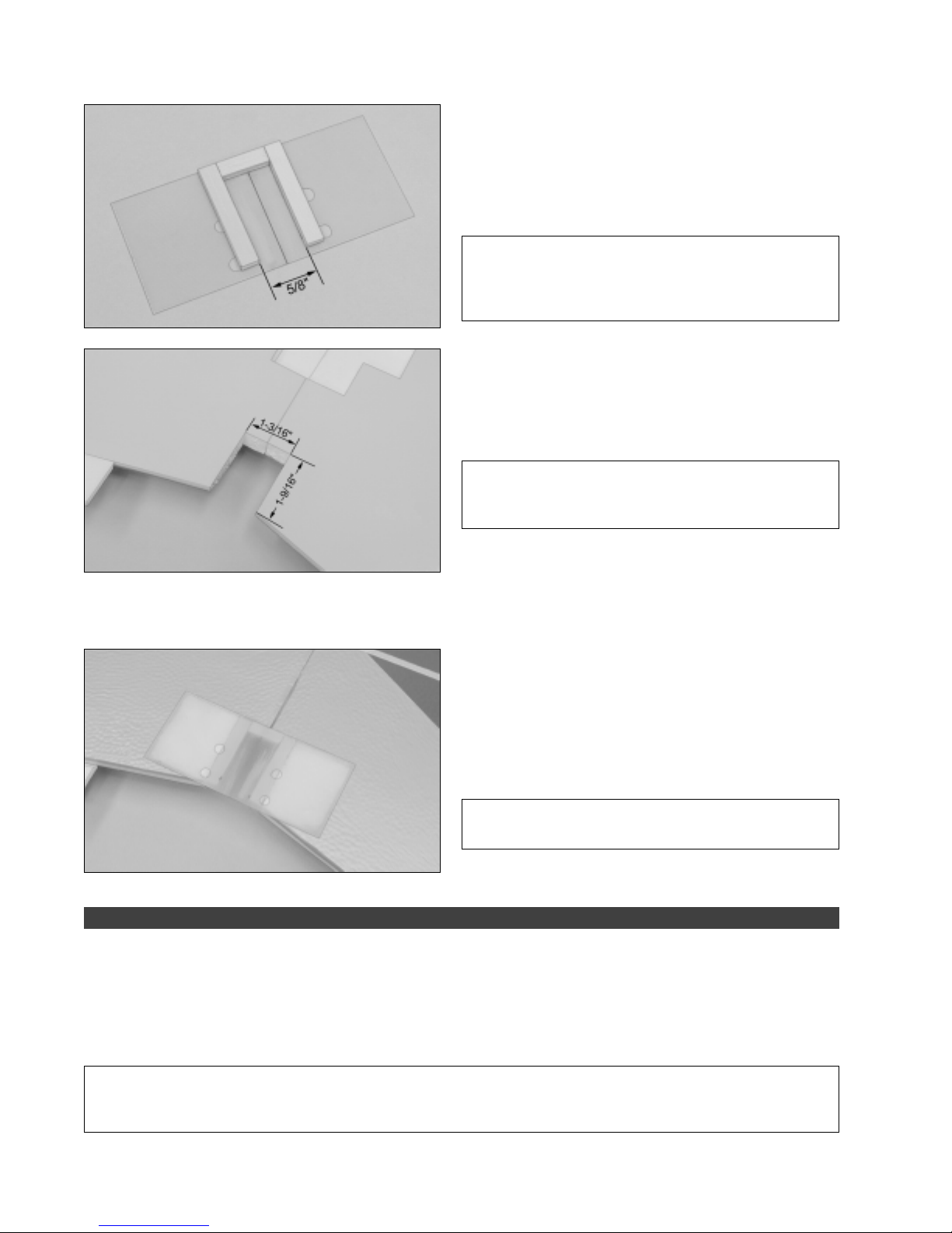
❑ Using thick C/A, carefully glue the three plywood motor
rails to one side of the fiberglass motor plate, making sure to
roughen the fiberglass first so that the C/A will stick to it.
Use the centerline you drew to help position the rails.
☞
There should be a 5/8" space between the two side rails.
✦✦
✦
✦✦
IMPORTANT
holes in the fiberglass motor plate. When you glue the
rails into place, the forward rail should be away from the
set of holes, as shown.
❑ Using a ruler and a modeling knife, carefully cut a notch
out of the trailing edge of the wing, 1-3/16" wide and extending
1-9/16" in front of the trailing edge, as shown.
✦✦
✦
✦✦
IMPORTANT
rails farther apart to suit your application, you will need to
cut the notch in the wing wider to match.
❑ Test-fit the motor plate assembly to the bottom of the wing. The fiberglass motor plate should fit firmly up against the
surface of the wing and the mounting rails should fit firmly within the notch you cut. The predrilled holes in the motor plate
should be toward the trailing edge of the wing and the forward mounting rail should be toward the front of the wing.
❑ When satisfied with the fit, glue the motor plate assembly
into place using 5 minute epoxy.
✦✦
✦
✦✦
Note the location of the set of predrilled
✦✦
✦
✦✦
Again, if you have spaced the mounting
Make sure to remove any covering material from the
☞
gluing surfaces and to lightly sand the fiberglass so that the
epoxy sticks to it.
✦✦
✦
✦✦
IMPORTANT
hang the trailing edge of the wing slightly. This is normal.
STEP 2: INSTALLING THE MOTOR
❑ Using a modeling knife, carefully cut away the foam from within the four predrilled holes in the motor plate.
❑ Insert one zip-tie up through each hole on one side of the motor plate (from the bottom), then loop them over and push
each one down through each hole on the other side of the motor plate.
❑ Slide the motor into place, making sure it's pushed as far forward as possible.
✦✦
✦
✦✦
IMPORTANT
motor. Also, don't worry about soldering motor wires onto the motor yet. We will remove the motor later and solder the
ESC motor wires directly to it.
12
✦✦
✦
✦✦
You may have to cut a couple of small notches in the foam to clear an area for the solder tabs on the
Visit our website at http://watt-age.globalhobby.com or for Customer Service at http://globalservices.globalhobby.com
✦✦
✦
✦✦
The back edge of the motor plate will over-
Page 13
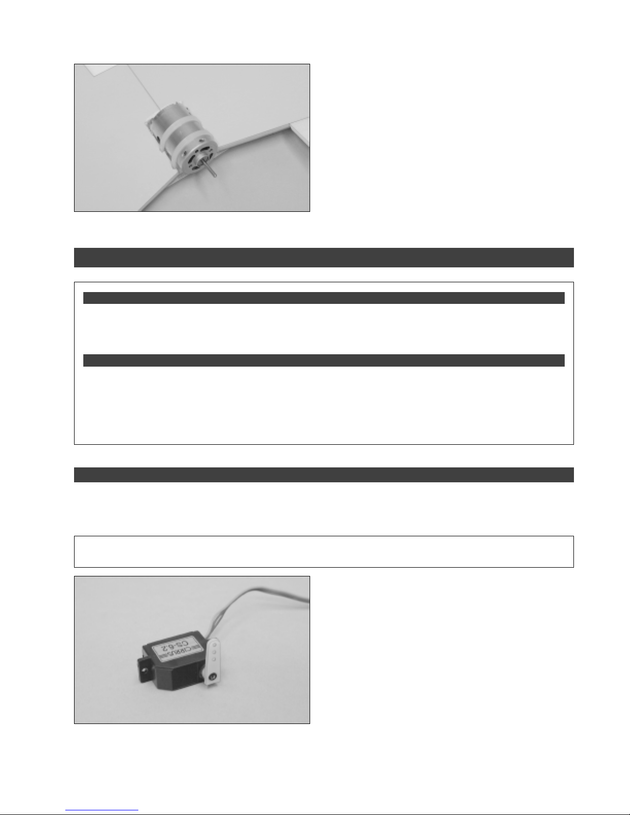
❑ With the motor in position, carefully pull the two zip-ties
tight to secure the motor firmly in place.
❑ Using wire cutters, cut away the excess zip-tie material,
making sure to leave enough extra so that you can remove
and reinstall them to solder the ESC motor leads onto the
motor later.
SECTION 7: CONTROL SYSTEMS INSTALLATION
YOU'LL NEED THE FOLLOWING PARTS FROM THE KIT:
❑ (1) Double-Sided Foam Tape
❑ (1) Velcro
❑ (2) M1.5 x 150mm Threaded Wires
❑ # 0 Phillips Head Screwdriver
❑ Magnum Z-Bend Pliers
❑ Wire Cutters
❑ Needle Nose Pliers
❑ Excel Modeling Knife
®
Mounting Material
YOU'LL NEED THE FOLLOWING TOOLS AND SUPPLIES:
❑ (2) Nylon Control Horns
❑ (2) Nylon Control Horn Backplates
❑ (2) Nylon Clevises
❑ Scissors
❑ Ruler
❑ Pencil
❑ K&S 30 Watt Soldering Iron
❑ Solder
STEP 1: INSTALLING THE SERVOS
❑ Connect your radio system and plug one servo into the aileron slot in your receiver and one servo into the elevator slot
in your receiver. Make sure that your radio transmitter is in elevon mode, then center both servos by double-checking that
the aileron and elevator trim levers on your transmitter are centered.
✦✦
✦
✦✦
IMPORTANT
✦✦
✦
✦✦
If your radio transmitter does not feature elevon mixing, you will need to purchase and use an
electronic elevon mixer.
❑ Using a modeling knife, cut away all but one arm from
the largest servo horn included with your servo.
❑ Repeat the previous procedures to install a servo horn to the second servo. When done, you should have one
right-hand and one left-hand servo.
Need help or have any questions? Call us at 1-714-963-0329 or send us an Email at [email protected]
❑ Install the servo horn onto the servo, making sure that
it's centered, as shown.
❑ Install the servo horn retaining screw to secure the servo
horn to the servo.
13
Page 14
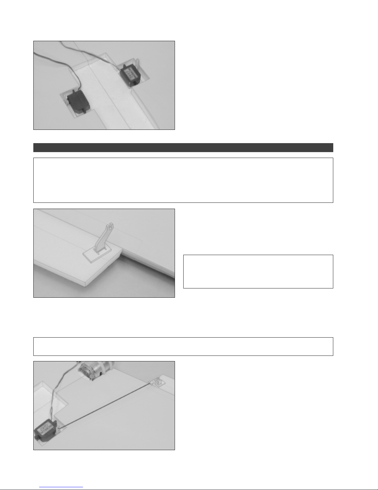
❑ Carefully install the two servos into the wing using
double-sided foam tape. When positioned properly, the
servos should be centered within the molded servo bays and
the servo horns should be toward the trailing edge of the
wing, as shown.
STEP 2: INSTALLING THE CONTROL HORNS, CLEVISES & PUSHRODS
✦✦
✦
✦✦
IMPORTANT
the propeller doesn't touch the ends of the ailerons. There should be an approximately 3/16" wide gap between the tips
of the propeller and the tip of the ailerons.
If you're using a different power system with a larger propeller, you will have to cut the ailerons shorter so they don't touch
the propeller. Make sure to do this before installing the control horns, clevises and pushrods.
✦✦
✦ Before continuing, we strongly suggest temporarily installing the propeller and double-checking that
✦✦
❑ Using a modeling knife, cut a small slot through one
aileron and install one control horn, making sure that the
control horn is 5/16" out from the end of the aileron (at the
hinge line) and that it is angled slightly toward the servo horn.
✦✦
✦
✦✦
IMPORTANT
sure that the flat portion of the control horn backplate faces
away from the aileron, and make sure to push the backplate
until you hear it "click" firmly into place.
❑ Thread one nylon clevis onto one M1.5 x 150mm threaded wire and carefully snap the clevis into the control horn.
❑ With both the servo horn and the aileron centered, use a pencil to draw a mark on the pushrod wire where it crosses
the outermost hole in the servo horn.
✦✦
✦
✦✦
IMPORANT
centered, the bottom of the aileron should be flush with the straight edge.
✦✦
✦
✦✦
To center the aileron, hold a straight edge against the bottom of the wing. When the aileron is
❑ Remove the pushrod from the control horn and use
Z-Bend pliers to make a Z-Bend in the pushrod wire at the
mark you drew.
❑ Cut away the excess wire using a pair of wire cutters,
making sure to leave about 1/8" of wire beyond the Z-Bend.
❑ Install the pushrod wire into the outermost hole in the
servo arm, then snap the clevis into the control horn.
✦✦
✦
✦✦
When installing the control horn, make
14
Visit our website at http://watt-age.globalhobby.com or for Customer Service at http://globalservices.globalhobby.com
Page 15
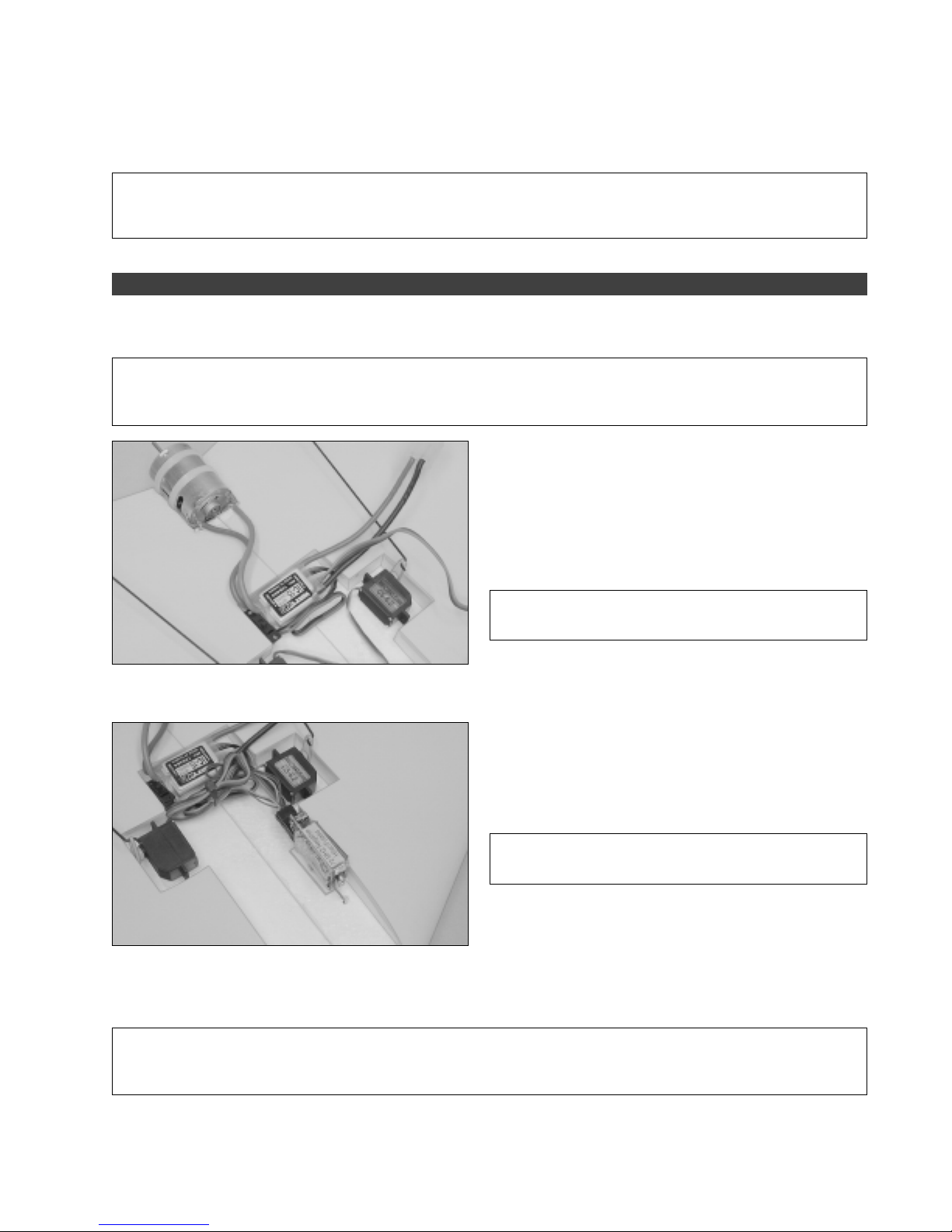
❑ Repeat the previous procedures to install the second control horn and pushrod assembly on the other side of the wing.
✦✦
✦
✦✦
IMPORTANT
installation of the pushrods. We will adjust them later to the correct center-trim position after the wing tip fences are
glued into place.
STEP 3: INSTALLING THE ESC & RECEIVER
❑ Cut off the plugs from the motor wires on your ESC and carefully solder the motor wires directly to the motor. As
mentioned previously, you may want to remove the motor from the airplane to do this so you don't melt the foam.
✦✦
✦
✦✦
IMPORTANT
in reverse. This means that you should solder the negative motor wire to the positive terminal and the positive motor
wire to the negative terminal. The positive terminal has a red dot next to it.
✦✦
✦
✦✦
The center-trim position of the ailerons described previously is a general position given to allow
✦✦
✦
✦✦
Because the motor is mounted in a pusher configuration, you must solder the motor wires to the motor
❑ Mount your ESC as far back in the molded radio bay as
possible, using a small piece of double-sided foam tape.
If your ESC features an on/off switch like ours, you can
☞
mount that to the edge of the molded radio bay using a small
piece of double-sided foam tape.
✦✦
✦
✦✦
IMPORTANT
as possible to allow room for the flight battery to be installed.
✦✦
✦
✦✦
The ESC must be mounted as far back
❑ Plug one servo lead into the aileron slot in your receiver and the other servo lead into the elevator slot, then plug the
ESC lead into the throttle slot.
❑ Mount the receiver up against the side of the molded
radio bay, using a small piece of double-sided foam tape.
✦✦
✦
✦✦
IMPORTANT
you should mount your receiver on its side like we show.
❑ Make a small hole through the bottom of the wing, directly in front of the receiver, to run the receiver antenna out of.
Extend the antenna along the bottom of the wing, parallel to the leading edge, and secure it to the tip of the wing, using a
piece of clear tape.
✦✦
✦
✦✦
IMPORTANT
antenna is secured firmly to the bottom of the wing, too. You don't want it to come loose during flight or it will fly back into
the propeller and be cut off. Doh!!
✦✦
✦
✦✦
Do not cut off the excess antenna. Let the excess hang past the wing tip. Double-check that the
✦✦
✦
✦✦
So that the flight battery will fit properly,
Need help or have any questions? Call us at 1-714-963-0329 or send us an Email at [email protected]
15
Page 16
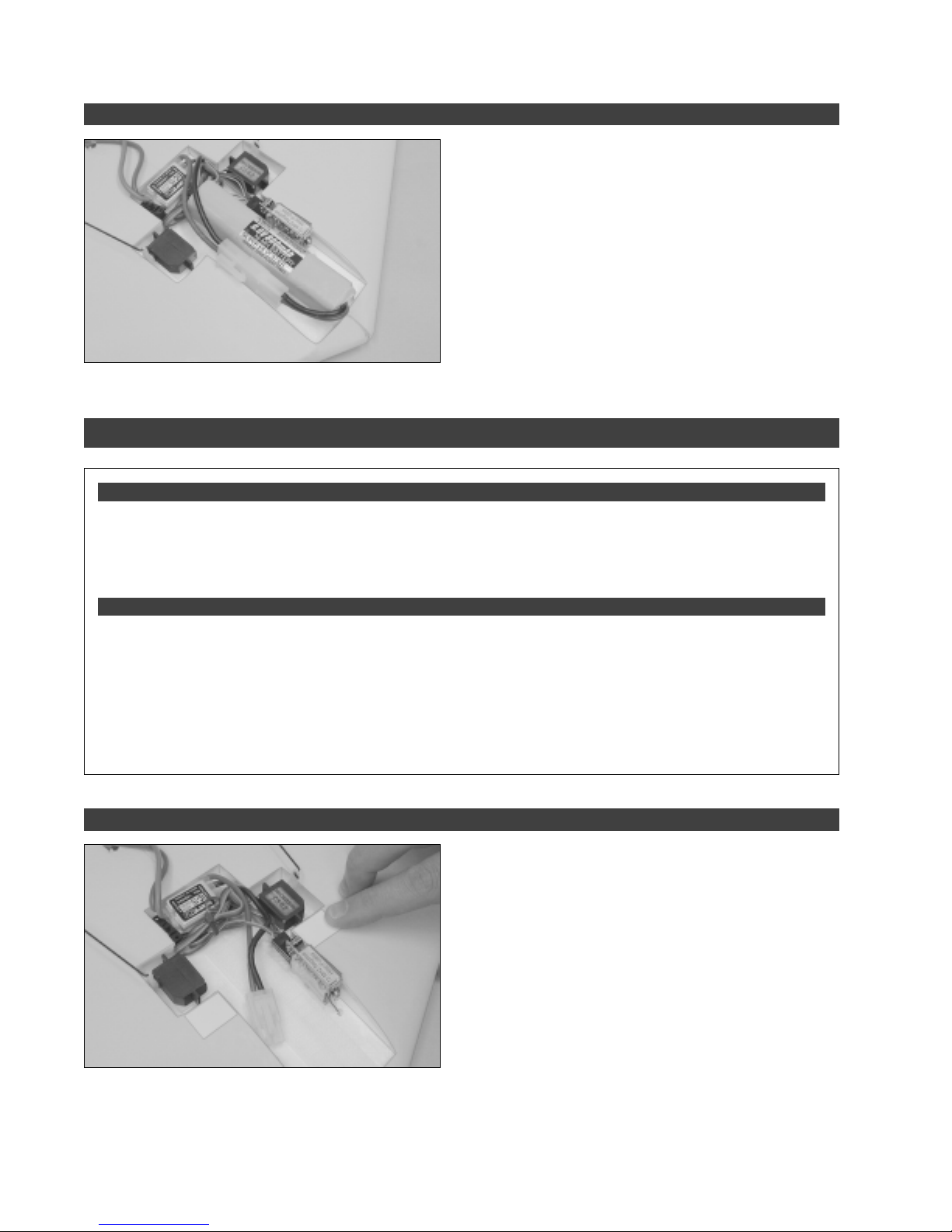
STEP 4: INSTALLING THE FLIGHT BATTERY
SECTION 8: FINAL ASSEMBLY
YOU'LL NEED THE FOLLOWING PARTS FROM THE KIT:
❑ (2) Wing Tip Fences
❑ (1) Plastic Hatch Cover
❑ (1) Plastic Hand-Launch Fairing
❑ (1) White Plastic Mounting Board (2 Parts)
YOU'LL NEED THE FOLLOWING TOOLS AND SUPPLIES:
❑ Kwik Bond 5 Minute Epoxy
❑ # 1 Phillips Head Screwdriver
❑ 1.5mm Hex Wrench
❑ Adjustable Wrench
❑ Excel Modeling Knife
❑ Scissors
❑ Ruler
❑ Install your flight battery on the centerline of the molded
radio bay, using the strip of self-adhesive Velcro
Before removing the flight battery, we suggest allowing
☞
the adhesive on the Velcro
ensure that the Velcro
®
to cure for 24 hours. This will
®
won't pull off of the flight battery or
®
.
out of the radio bay when you remove the flight battery.
❑ (2) M2 x 10mm Flange-Head Wood Screws
❑ (1) 5 x 2.5 Nylon Propeller
❑ (1) Propeller Adapter w/Washer, Nut & Grub Screw
❑ Pencil
❑ Masking Tape
❑ 220 Grit Sandpaper w/Sanding Block
❑ Paper Towels
❑ Rubbing Alcohol
❑ NHP Epoxy Mixing Sticks
❑ NHP Epoxy Mixing Cups
STEP 1: INSTALLING THE HATCH COVER
❑ Using a pair of scissors, carefully cut out the hatch cover along the molded scribe lines.
❑ Using 220 grit sandpaper with a sanding block, lightly sand the edges of the hatch cover smooth.
16
Visit our website at http://watt-age.globalhobby.com or for Customer Service at http://globalservices.globalhobby.com
❑ Apply the two pieces of white plastic mounting board to
the top of the wing. One piece should be positioned on each
side of the molded radio bay, directly in front of the molded
servo bay.
Page 17
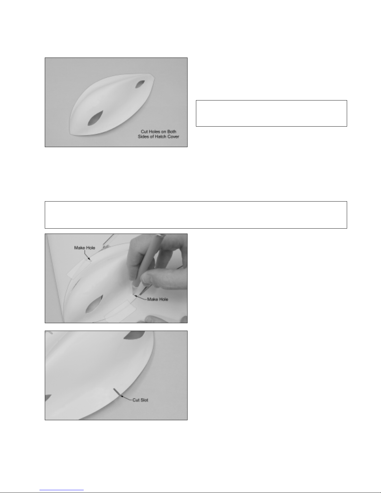
❑ Using a modeling knife, carefully cut an air-intake hole
and an air-exit hole in each side of the hatch cover, as shown.
✦✦
✦
✦✦
IMPORTANT
in the hatch cover to properly cool the flight battery and
ESC. Do not omit this procedure.
❑ Set the hatch cover into place and position it. When aligned properly, the hatch cover should be centered over the
centerline of the wing and the base of the hatch cover should fit flush against the top of the wing. In addition, the front of
the hatch cover should conform to the leading edge of the wing and the sides of the hatch cover should not interfere with
the servo arms.
❑ When satisfied with the alignment, hold the hatch cover in place using a couple of pieces of masking tape.
✦✦
✦
✦✦
IMPORTANT
hatch cover is preventing it. If so, rearrange the wiring to fit. Also, don't forget that you need to cut out the small molded
triangle shape in the back of the hatch cover to allow room for the motor wires to pass through.
✦✦
✦
✦✦
If the hatch cover does not fit flush against the top of the wing, it may be because the wiring under the
❑ With the hatch cover firmly in place and aligned, use the
tip of your modeling knife to make a pilot hole through each
side of the hatch cover and into the plastic mounting board.
Position each pilot hole over the center of the mounting board.
✦✦
✦
✦✦
You must cut air-intake and air-exit holes
❑ Carefully thread the two M2 x 10mm flange-head wood screws into the pilot holes you made in the plastic mounting
board. Thread them in far enough so that the hatch cover will slide just underneath the screw heads.
Need help or have any questions? Call us at 1-714-963-0329 or send us an Email at [email protected]
❑ Remove the hatch cover and use a modeling knife to
cut a narrow slot from each pilot hole out to the edge of the
hatch cover.
Make the slot wide enough that it will slide over the
☞
threaded portion of the M2 x 10mm flange-head wood screws.
17
Page 18
STEP 2: INSTALLING THE HAND-LAUNCH FAIRING
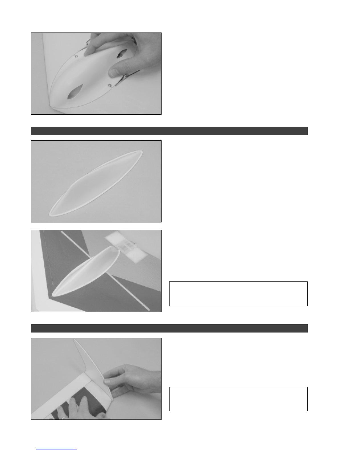
❑ Install the hatch cover by squeezing it together slightly
and sliding the slots underneath the heads of the two wood
screws.
If necessary, adjust the height of the wood screws to
☞
allow the hatch cover to slide underneath them, but still hold it
down firmly.
❑ Using a pair of scissors, cut out the hand-launch fairing,
making sure to leave a 1/8" lip around the base of the fairing
to use as a gluing surface.
❑ Using 220 grit sandpaper with a sanding block, sand the
edges of the fairing smooth.
STEP 3: INSTALLING THE WING TIP FENCES
❑ Carefully glue the hand-launch fairing to the bottom of
the wing, using a generous amount of 5 minute epoxy. The
fairing should be aligned with the centerline of the wing and
the back edge of the fairing should be pushed up against the
front edge of the fiberglass motor plate. Also note that the
taller portion of the fairing is toward the back of the wing.
✦✦
✦
✦✦
IMPORTANT
forget to remove any covering material from the gluing
surfaces and to roughen the gluing surfaces of the plastic.
❑ Using 5 minute epoxy, carefully glue the two wing tip
fences into place. To align them properly, the front and
bottom edges of the wing tip fences should be even with the
front and bottom edges of the wing tip, and the wing tip fences
should be aligned 90 degrees to the top of the wing.
✦✦
✦
✦✦
IMPORTANT
be careful not to glue them at an angle. They should be
straight up and down, not angled in or out.
✦✦
✦
✦✦
Before gluing the fairing into place, don't
✦✦
✦
✦✦
When gluing the wing tip fences into place,
18
Visit our website at http://watt-age.globalhobby.com or for Customer Service at http://globalservices.globalhobby.com
Page 19
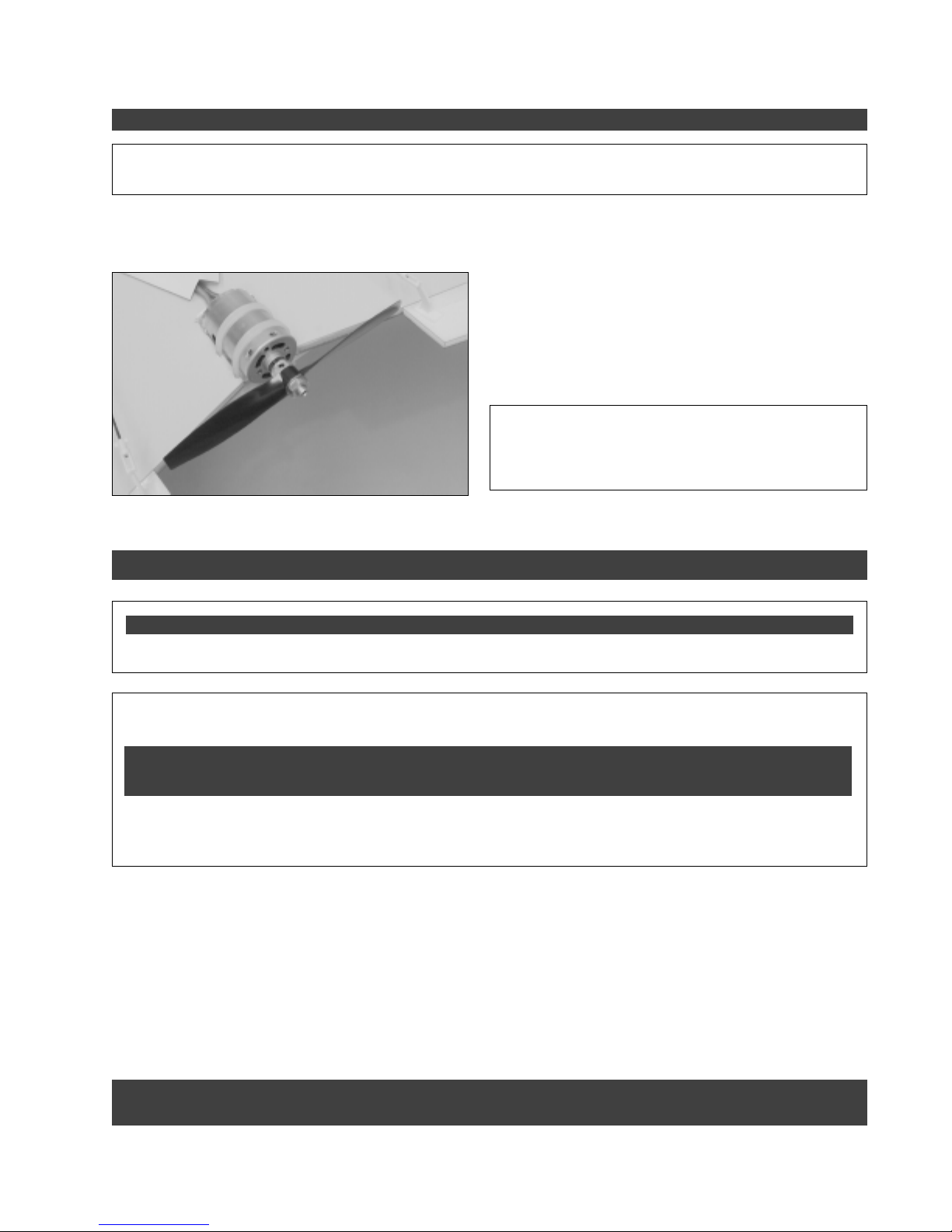
STEP 4: INSTALLING THE PROPELLER ASSEMBLY
✦✦
✦
✦✦
IMPORTANT
to the grub screw to prevent the grub screw from loosening during flight.
❑ Slide the propeller adapter onto the motor shaft and tighten the grub screw firmly, using a hex wrench.
Make sure that the propeller adapter does not rub against the motor.
☞
✦✦
✦
✦✦
When installing the propeller adapter in the next procedure, we strongly suggest applying threadlocker
❑ Slide the propeller onto the propeller adapter (making
sure that the molded numbers on the front of the propeller
are toward the front of the wing) and secure it into place,
using the flat washer and hex nut provided. Make sure to
tighten the nut firmly to keep the propeller from coming loose
during flight.
✦✦
✦
✦✦
IMPORTANT
in a pusher configuration, the propeller must be installed
backwards. Verify that you install the propeller with the
molded numbers toward the front of the wing.
✦✦
✦
✦✦
Because the motor is mounted and wired
SECTION 9: BALANCING THE HYPER WING 400 EP
YOU'LL NEED THE FOLLOWING TOOLS AND SUPPLIES:
❑ Ruler
✦✦
✦
✦✦
IMPORTANT
control and crash!
✦✦
✦
✦✦
It is critical that your airplane be balanced correctly. Improper balance will cause your airplane to lose
❑ Pencil
Center of Gravity Location:
6-1/8" back from the leading edge of the wing, measured at the centerline of the wing.
✦✦
✦
✦✦
WARNING
a flying wing, we suggest not attempting to move the C/G forward or aft from its initial location. Doing so can result in
very erratic flight characteristics.
Balance the Hyper Wing 400 EP with the flight battery installed.
☞
❑ Measure and draw two marks on the bottom of the wing, 6-1/8" back from the leading edge, measured at the
centerline of the wing.
❑ Place your fingers on the marks, and carefully lift the airplane. If the nose of the airplane falls, the airplane is nose
heavy. To correct this, move the flight battery back far enough to bring the airplane into balance. If the tail of the airplane
falls, the airplane is tail heavy. To correct this, move the flight battery far enough forward to bring the airplane into balance.
When balanced correctly, the airplane should sit level or slightly nose down when you lift it up with your fingers at the C/G
location. It should not set with the tail down.
✦✦
✦
✦✦
This is the recommended C/G location. Because there is little margin of error when locating the C/G of
DO NOT FLY THE AIRPLANE OUTSIDE OF THE RECOMMENDED BALANCE POINT OR AN
Need help or have any questions? Call us at 1-714-963-0329 or send us an Email at [email protected]
UNCONTROLLABLE CRASH COULD RESULT!
19
Page 20

SECTION 10: CONTROL THROWS
✦✦
✦
✦✦
IMPORTANT
edge on the bottom of the wing, perpendicular to the hinge line, and adjusting the pushrods so that the elevons follow the
same angle as the bottom of the wing. Also, if you've glued the wing tip fences into position as described previously, the
tip of the elevons (at the trailing edge) will be even with the tip of the wing tip fences.
With the elevons in this centered position, they will both appear to be raised up in relation to the top of the wing. This is
normal and by design.
We recommend setting up the Hyper Wing 400 EP using the control throws listed below. These control throws are
suggested for initial test-flying because they will allow the airplane to fly smoother and make it easier to control.
✦✦
✦
✦✦
Before setting the control throws, you must first center both elevons. This is done by placing a straight
TEST-FLYING
Elevons Up & Down: 3/8" Each Direction
Elevons Right & Left: 3/8" Each Direction
✦✦
✦
✦✦
IMPORTANT
Once you're familiar with the flight characteristics of the airplane, you might want to increase the control throws to the
sport-flying settings listed below. These control throws will make the airplane more responsive and allow you to do basic
aerobatics with ease.
✦✦
✦
✦✦
When measuring the control throws, measure from the widest point of the control surfaces.
SPORT-FLYING
Elevons Up & Down: 5/8" Each Direction
Elevons Right & Left: 5/8" Each Direction
✦✦
✦
✦✦
IMPORTANT
Higher control throws will cause the airplane to be extremely control-sensitive and possibly result in a crash if you
are not careful.
✦✦
✦
✦✦
We do not suggest increasing the control throws beyond the recommended Sport-Flying settings.
SECTION 11: PREFLIGHT CHECK & SAFETY
●
Check the operation of the throttle. To do this, do the following:
A) Plug the flight battery into the ESC and turn on the radio system.
✦✦
✦
✦✦
WARNING
Never allow hands or clothing to get in the way of the propeller when the radio is turned on. Sudden unwanted radio
signals, or turning the radio on with the throttle stick set at full throttle, can turn the motor on unintentionally. Always
make sure that the throttle control stick is set to idle before turning on the transmitter.
should turn on the motor. Gradually moving the stick to the full forward position should result in the motor running at
full power.
✦✦
✦
✦✦
Do not turn the receiver on unless the transmitter is turned on first. Always turn the transmitter on first.
B) When the throttle control stick is at the idle position, the motor should be off. Moving the stick forward
Some ESCs will give you more proportional control than others. Your ESC may also have a manual control
☞
adjustment screw that must be adjusted prior to using the ESC. (Refer to your ESC's operating guide for further
information.)
20
Visit our website at http://watt-age.globalhobby.com or for Customer Service at http://globalservices.globalhobby.com
Page 21

PREFLIGHT CHECK & SAFETY, CONTINUED....
●
Cycle the flight battery three times. When NiMH or NiCD batteries are new they need to be used 2-3 times before
they will produce their top voltage and duration. To cycle them, simply charge the battery and then run the motor (at
low speed to prevent damaging it) until the motor stops. Allow the battery and motor to cool, then repeat this
procedure two more times.
●
Check the condition of the transmitter batteries. They should be fully charged.
●
Check every bolt and every glue joint in the airplane to ensure that everything is tight and well-bonded.
●
Double-check that all of the control horns are tight.
●
Double-check the balance of the airplane. Do this with the flight battery installed.
●
Check the control surfaces. They should all move in the correct direction and not bind.
●
If your radio transmitter is equipped with dual rate switches, double-check that they are on the low-rate setting for
your first few flights.
●
Check to ensure that all of the control surfaces are moving the proper amount in both low and high rate settings.
●
Check the receiver antenna. It should be fully extended and secured firmly to the bottom of the wing.
●
Double-check the wiring of the motor and the propeller. Because the motor is installed in a pusher configuration, the
motor should be wired backwards and the propeller should be installed backwards. If not, there will be limited forward
thrust produced by the power system and the airplane will not fly.
SECTION 12: HAND-LAUNCHING THE HYPER WING 400 EP
✦✦
✦
✦✦
IMPORTANT
●
Carefully double-check the balance of the airplane. The balance point is located 6-1/8" behind the leading edge of the
wing, measured at the centerline.
●
Double-check that both elevons are centered, as described in section 10.
●
Double-check that the elevons are moving in the proper direction both up and down and right and left.
●
Double-check that the control throws are set correctly, as described in section 10.
●
Double-check that the power system is providing full thrust. At full power, the airplane should feel like it's pulling out of
your hand.
Hand-launching should always be done into the wind.
To hand-launch the airplane, gently grasp the hand-launch fairing between your thumb and forefingers. Hold the airplane
above shoulder level and turn on the motor to full power. With the motor running at full power, firmly toss the airplane
straight ahead and level. Do not throw it up at an angle or throw it too hard. Allow the airplane to fly straight and level to
pick up airspeed, then climb to your desired altitude. Be careful not to climb too steeply after hand-launching or you could
stall the airplane.
✦✦
✦
✦✦
Before your first flight, take a moment to double-check the following points:
Need help or have any questions? Call us at 1-714-963-0329 or send us an Email at [email protected]
21
Page 22

SECTION 13: REPLACEMENT PARTS LIST
Wattage stocks a complete line of replacement parts for your Hyper Wing 400 EP. Listed below are the replacement
parts that are available along with their respective part numbers for easy ordering convenience. We suggest ordering
directly from your local dealer. If your dealer does not stock Wattage products, you can order directly from us at the
address shown below:
Global Services
18480 Bandilier Circle
Fountain Valley CA 92708
Phone: (714) 963-0329 Fax: (714) 964-6236
http://globalservices.globalhobby.com
On the Web
Wattage Hyper Wing 400 EP ............................ 128445
Wattage Hyper Wing 400 EP w/Battery & ESC ... 128446
Instruction Manual ............................................. 144983
Molded Hatch Cover & Hand-Launch Fairing ... 144984
Wing Tip Fence Set (2) ..................................... 144985
Wing Panel Set (2) ............................................ 144986
Fiberglass Wing Dowels ................................... 144987
Fiberglass Motor Plate & Misc. Hardware ........ 144988
Aileron Set (2) ..................................................... 144989
Self-Adhesive Decal "Skins" Set ........................ 144990
380 Direct Drive Motor ....................................... 131338
Propeller Adapter Assembly ............................... 131335
5 x 2.5 Nylon Propeller ....................................... 131380
Control Horn Set ................................................. 152112
Pushrod Wire Set ............................................... 152110
22
Visit our website at http://watt-age.globalhobby.com or for Customer Service at http://globalservices.globalhobby.com
Page 23
PRODUCT EVALUATION SHEET
Telling us what you like and don't like determines what model kits we make and how we make them. We would appreciate it if you
would take a few minutes of your time to answer the following questions about this kit and your modeling interests. Simply fold this
form on the dotted lines, seal with tape and mail it to us. Do not use staples and make sure our address faces out.
Global Hobby Distributors will not disclose the information it collects to outside parties. Global Hobby Distributors does not sell,
trade, or rent your personal information to others. Your privacy is important to us.
1) Kit: Wattage Hyper Wing 400 EP Standard # 128445
Wattage Hyper Wing 400 EP Deluxe # 128446
2) Where did you learn about this kit?
❑ Magazine Ads ❑ Friend
❑ Hobby Shop ❑ Other
❑ Internet
3) What influenced you the most to buy this kit?
❑ Magazine Ads ❑ Price
❑ Type of Model ❑ Box Art
❑ Recommendation ❑ Other
❑ Internet
4) Did you have any trouble understanding the written
instructions? If yes, please explain.
❑ Yes ❑ No
____________________________________
____________________________________
____________________________________
____________________________________
5) Did you have any trouble understanding any of the
photographs? If yes, please explain.
❑ Yes ❑ No
____________________________________
____________________________________
____________________________________
Cut Along Dotted Line
____________________________________
6) Were any of the kit parts:
❑ Damaged ❑ Wrong Size
❑ Missing ❑ Wrong Shape
If you checked any of the boxes above, did you
contact our Customer Service Department to resolve
the problem?
❑ Yes ❑ No
7) Was any of the assembly difficult for you? If yes,
please explain.
❑ Yes ❑ No
____________________________________
____________________________________
____________________________________
____________________________________
8) What did you like most about this kit?
❑ Assembly Manual ❑ Parts Fit
❑ Hardware Supplied ❑ Price
❑ Other
____________________________________
____________________________________
____________________________________
9) What did you like least about this kit?
❑ Assembly Manual ❑ Parts Fit
❑ Hardware Supplied ❑ Price
❑ Other
____________________________________
____________________________________
____________________________________
10) Are you satisfied with the finished model? If no,
please explain.
❑ Yes ❑ No
____________________________________
____________________________________
____________________________________
____________________________________
11) How does this kit compare to similar kits by other
manufacturers?
❑ Better ❑ As Good
What is Your Age Group:
❑ 10 & Under ❑ 11 - 20 ❑ 21 - 30 ❑ 31 - 40 ❑ 41 - 50 ❑ 51 - 60 ❑ 61 - 70 ❑ 71 +
How Many Years Have You Been in the Hobby?
❑ Less than 1 ❑ 2 - 4 ❑ 5 - 7 ❑ 8 - 10 ❑ 11 - 15 ❑ 16 - 20 ❑ 20 or More
How Many Models Have You Purchased In the Last Year?
❑ 0 - 1 ❑ 2 - 4 ❑ 5 - 7 ❑ 8 - 10 ❑ 10 or More
Please List any Other Modeling Interests or any Additional Information about This Product: ______________________
_____________________________________________________________________________________
_____________________________________________________________________________________
_____________________________________________________________________________________
_____________________________________________________________________________________
Need help or have any questions? Call us at 1-714-963-0329 or send us an Email at service@globalhobby.net
23
Page 24

_____________________________
_____________________________
_____________________________
(Return Address Here)
Fold along dotted line
Global Hobby Distributors
Attn: Global Services
18480 Bandilier Circle
Fountain Valley CA 92728-8610
Fold along dotted line
Post Office will
not deliver
without proper
postage
24
Visit our website at http://watt-age.globalhobby.com or for Customer Service at http://globalservices.globalhobby.com
 Loading...