

1241 Bundy Boulevard, Winona, Minnesota USA 55987
Phone: +1 (507) 454-5300, Fax: +1 (507) 452-4507
http://www.watlow.com
Please consult this user’s manual when you place your new
DIN-A-MITE in service. It contains all the necessary
information to mount and wire it into the application. This
manual also contains all pertinent specifications and
semiconductor fusing recommendations. Please refer to
national and local electrical code safety guidelines whenever
you install electrical equipment.
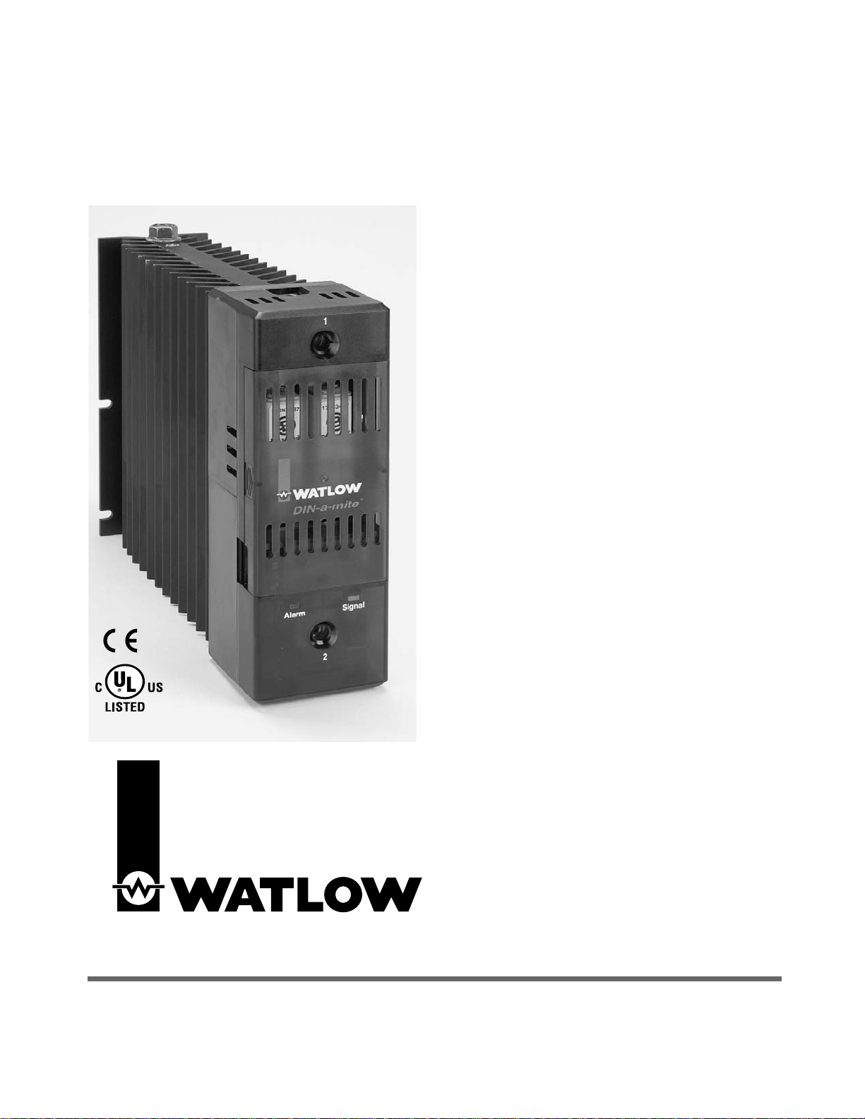
This DIN-A-MITE product is capable of switching up to 100
amperes single-phase, at 600V
Å (ac) at 30°C (86°F),
depending on the model selected. It is electrically touch-safe
and includes standard back-panel mounting, on-board
semiconductor fuses, and a current transformer option for
external load current monitoring. Shorted SCR alarm output
option is also available.
The DIN-A-MITE Style D mounting footprint matches that of
an industry-standard 100-amperes mercury displacement
relay. This DIN-A-MITE is CE-approved, UL
®
508-listed and
C-UL
®
.
0600-0025-0013 R
ev F
Supersedes 0600-0025-0013 R
ev. E
February 2007
DIN-A-MITE
®
Style D
Solid-State Power Controller
User’s Manual

Specifications
2 WATLOW DIN-A-MITE Style D User’s Manual
Operator Interface
• Command signal input and indication light
• Alarm output and indication light
Amperage
• Single-phase, 80A output maximum at 50°C (122°F) into a resistive
load. See the Output Rating Curve chart on page 3.
• Maximum surge current for 16.6 milliseconds, 1,800-amp peak
• Maximum I2t for fusing: 16,200 A2sec
• Latching current: 500mA minimum
• Holding current: 200mA minimum
• Off-state leakage: 1mA at 25°C (77°F) maximum
• 200KA SCCR type 1 and 2 approved with the recommended fusing
(see page 3)
Line Voltage
• 24 to 48VÅ (ac) units: 20 minimum to 53VÅ (ac) maximum
• 120 to 240VÅ (ac) units: 48 minimum to 265VÅ (ac) maximum
• 277 to 480VÅ (ac) units: 85 minimum to 528VÅ (ac) maximum
• 277 to 600VÅ (ac) units: 85 minimum to 660VÅ (ac) maximum
• 50/60 Hz independent +/- 5%
Control Mode, Zero Cross
• Input Control Signal Type C: VÎ (dc) input contactor. To increase
service life, the cycle time should be less than three seconds.
• Input Control Signal Type K: VÅ (ac) input contactor. To increase
service life, the cycle time should be less than three seconds.
• Input Control Signal Type F: 4 to 20mAÎ (dc) variable time base
control
Input Command Signal
• AC contactor
24VÅ ±10%, 120VÅ +10% / -25%, 240VÅ (ac) +10% / -25% @ 25mA
maximum per controlled leg
• Do not use the DIN-A-MITE Vac-input models with a temperature
controller that includes an RC snubber circuit across its output.
Remove the RC snubber circuit before placing the DIN-A-MITE into
service.
• DC Contactor
4.5VÎ to 32VÎ (dc): maximum current @ 4.5VÎ (dc) is 6mA per leg.
Add 3mA if alarm option is included
• Loop powered linear current
4mAÎ to 20mAÎ (dc): loop-powered. Input Type F0 and F1 options
only. (Requires current source with 6.2VÎ (dc) available. No more
than three DIN-A-MITE inputs connected in series)
Linearity (Input Control Signal Type F)
• Full on point 19.5 to 19.9mAÎ (dc), maximum voltage of 6.2V peak.
• ±5% input to output power accuracy, 0% to 100% of span (4.3 to
19.7mA or 12.3 to 19.7mA).
• Temperature stability is less than 0.15%/°C change.
Alarm
Shorted SCR Alarm Option
• Alarm state when the input command signal off and a 15A or more
load current is detected by the current transformer.
Alarm Output
• Energizes on alarm, non-latching
• Triac 24 to 240VÅ (ac) external supply with a current rating of 300mA
@ 25°C (77°F), 200mA @ 50°C (122°F), 100mA @ 80°C (176°F) and
a holding current of 200 µA with a latching current of 5mA typical
Current Sensing
• On-board current transformer (CT), typically 0.2VÅ (ac) output signal
per ampere sensed
Agency Approvals
• CE with proper filter:
89/336/EEC Electromagnetic Compatibility Directive
EN 61326: Industrial Immunity Class A emissions
Not suitable for Class B emissions environment
73/23/EEC Low Voltage Directive
EN 50178 Safety Requirements
• UL® 508-listed and C-UL®File E73741
Input Terminals
• Compression: Will accept 0.13 to 3.3 mm2(26 to 12 AWG) wire
• Torque to 0.5 Nm (4.4 in-lb) maximum with a 3.5 mm (1/8 in) blade
screwdriver
• Wire strip length 7 mm (0.28 in)
Line and Load Terminals
• Compression: Will accept 13.3 to 34 mm2(6 to 2 AWG) wire
• Torque to 9.0 to 10.1 Nm (80 to 90 in-lb) maximum with a 3/16 inch
Allen head
• Wire strip length 17.5 mm (0.69 in)
Operating Environment
• Operating temperature range: 0 to 85°C (32°F to 185°F)
• 0 to 90% RH (relative humidity), non-condensing
• Vibration: 2 g, 10 Hz to 150 Hz, applied in any one of three axes
• Storage temperature: -40 to 85°C (-40°F to 185°F)
• Insulation tested to 3,000 meters
• Installation Category III, pollution degree 2
Mounting
• Standard back panel mounting; fits the same mounting pattern as a
100 A, single-phase mercury displacement relay
• Mounting holes offer clearance for an M5 (No. 10) screw
• On-board semiconductor fusing, Bussmann part number 170N3437
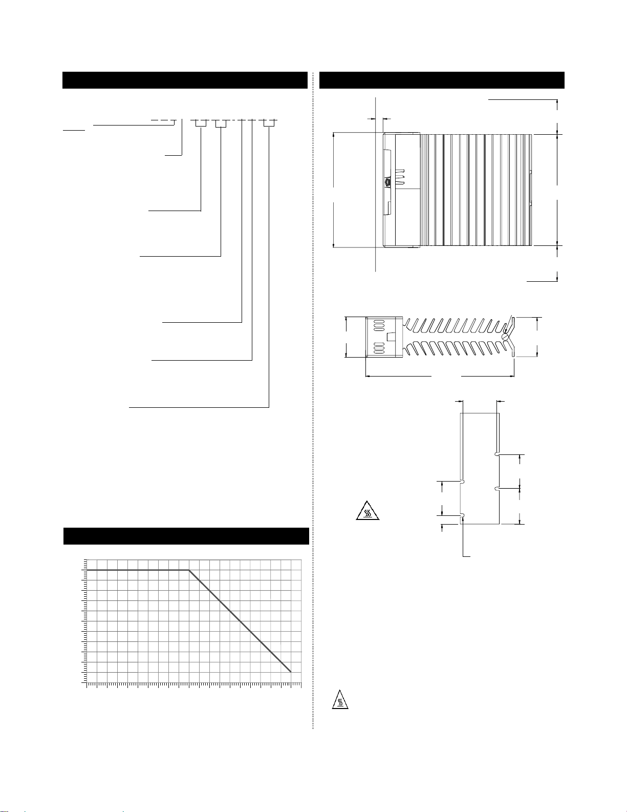
Dimensions
• Height: 185 mm (7.28 in)
• Width: 66 mm (2.58 in)
• Depth: 239 mm (9.41 in)
• Weight: 2.9 kg (6.3 lb)
Specifications are subject to change without notice.
DIN-A-MITE Style D, solid-state power controller
Part Number D
D 1 0 - __ __ __ __ - __ __ __ __
Phase
1 = Single-phase, one
controlled leg
Cooling and Current Rating
0 = Natural convection; current rating
80A @ 50°C (122°F)
Note: See the output rating curve
for the current rating at other
temperatures.
Line and Load Voltage
02 = 24 to 48VÅ (ac)
24 = 120 to 240VÅ (ac)
48 = 277 to 480VÅ (ac)
60 = 277 to 600VÅ (ac)
Input Control Signal
C0 = 4.5 to 32VÎ (dc) contactor
F0 = 4 to 20mAÎ (dc) proportional
F1 = 12 to 20mAÎ (dc) proportional
K1 = 22 to 26VÅ (ac) contactor
K2 = 100 to 120VÅ (ac) contactor
K3 = 200 to 240VÅ (ac) contactor
Current Sensing or Alarm
0 = None
1 = Load current transformer
S = Shorted SCR alarm
User Manual Language
0 = English
1 = German
2 = Spanish
3 = French
Custom Options
00 = Standard
Ordering Information
Output Rating Curve
WATLOW DIN-A-MITE Style D User’s Manual 3
ç
Ó
3
5
203 mm
(8.00 in)
203 mm (8.00 in) clearance for air
flow and bending radius
203 mm
(8.00 in)
203 mm (8.00 in) clearance for air flow and bending radius
178 mm
(7.00 in)
185 mm
(7.28 in)
13 mm
(0.50 in)
13 mm (0.5 in) clearance
for air flow
Unit Dimensions
Top
Side
Mounting
Footprint
ç WARNINGS:
Ó
3
WARNING: Only authorized and qualified
personnel should be allowed to install and
perform preventive and corrective maintenance
on this unit. Failure to do so could result in
damage to equipment, and personal injury or
death.
5
WARNING: Hot surface, do not touch the heat
sink. Failure to follow this guideline could result
in personal injury.
Note:
• Recommended fusing options to meet 200KA SCCR, type 1 and
2 approved. All other fuse combinations are defaulted to 5KA
SCCR per UL508A and NEC guidelines.
Watlow part number: 0808-0096-0000
Bussmann part number: 170N3437
85
80
75
70
65
60
55
50
45
40
35
30
25
Maximum Ambient Temperature Inside Cabinet (°C)
DIN-A-MITE Style D Natural Convection at 100% on
0 5 10 15 20 25 30 35 40 45 50 55 60 65 70
Current (Amperes) Into a Resistive Load
75 80 85 90 95 100 105
66 mm
(2.58 in)
9.5 mm minimum diameter (3/8 in to 16 UNC)
Grounding Screw
239 mm
(9.41 in)
54 mm
(2.13 in)
64 mm
(2.50 in)
67 mm
(2.63 in)
67 mm
(2.63 in)
13 mm
(0.50 in)
61 mm
(2.38 in)
Allowance For No. 10 Fastener
Metric = M5

4 WATLOW DIN-A-MITE Style D User’s Manual
After removing all power, use a 7/16-inch nut driver to remove
fuse mounting nuts. Torque to 4.52 Nm (40 in-lb).
ç WARNINGS:
Ó 1 WARNING: Use National Electric (NEC) or other
country-specific standard wiring practices to install
and operate the DIN-A-MITE. Failure to do so may
result in damage to equipment and property,
and/or injury or loss of life.
Ó 2 WARNING: Wiring examples show L2 in phase-to-
phase, 200VÅ (ac) and above configuration. In
phase-to-neutral, 100VÅ (ac) and above
applications, L2 is neutral and must not be fused
or switched. Failure to follow this guideline could
result in personal injury or death.
Ó3 WARNING: Only authorized and qualified personnel
should be allowed to install and perform
preventive and corrective maintenance on this
unit. Failure to do so could result in damage to
equipment, and personal injury or death.
Ó
4
WARNING: Do not use the DIN-A-MITE Vac-input
models with a temperature controller that includes
an RC snubber circuit across its output. Remove
the RC snubber circuit before placing the DIN-AMITE into service.
5
WARNING: Hot surface, do not touch the heat sink.
Failure to follow this guideline could result in
personal injury.
ç
Ó
3
System Wiring Example
ç
Ó
3
Fuse Replacement

WATLOW DIN-A-MITE Style D User’s Manual 5
Single-Phase Output and Input Wiring
ç
Ó
2
Ó
3
Ó
4
Shorted SCR Alarm
The Watlow DIN-A-MITE alarm option provides an alarm output for shorted SCR conditions. A shorted SCR alarm is detected
when there is no command signal and a load current is detected. The alarm output is then energized. This is a non-latching
alarm.
Torque Procedure
1. While connecting the line and load wires, ensure that all wire strands are inside the connector. Do not allow loose wire
strands to hang out of the connector. Once you have installed the wire, torque these same connections to 9.0 to 10.1 Nm
(80 to 90 in-lb). Use a dial or digital-type torque wrench and hold the torque at 9.0 to 10.1 Nm (80 to 90 in-lb) for 30 seconds.
The 30-second hold allows the wire to settle, minimizing the wire cold flow.
2. Re-torque the same connections after 48 hours.
3. Develop a maintenance program to re-torque all load and line connections every three to six months.
NOTE: L1 and L2 terminals are 3/16-inch Allen head screws.
4 to 20mA input:
(+)
L1
L1 for all
Limit Control
3
(-)
4
1
Contacts
(if required)
voltages
Alarm or Current Transformer Output
Alarm or Current Transformer Output
4.5 to 32VÎ (dc) input:
VÅ (ac) input
(Model Number-Dependent)
Current Sensing Option
DD10 - _ _ _ _ - 1 _ _ _
Current Monitor
or Indication
Non-latching Alarm Option
DD10- _ _ _ _ - S _ _ _
VÅ
1A
Alarm
Indicator
5
6
5
6
(+)
(-)
On-board
Current
Transformer
On-Board
Triac
3
4
3
4
5
6
Semiconductor
Fuses
Open Heater
Alarm Adjust
2
Heater
Ground lug supplied. Use
Thomas & Betts crimp tool
options below or equivalent.
Use 6 AWG copper conductor.
TBM 20S
TBM 25S
TBM 5
TBM 6
TBM 8
TBM 60RS
Phase-to-phase
200VÅ (ac)
and above
L2
Heater
Neutral
Phase-to-neutral
100VÅ (ac) and above
The neutral must not be switched.

Declaration of Conformity
DIN-A-MITE®“D” Power Controller
Watlow Winona, Inc.
1241 Bundy Blvd.
Winona, MN 55987 USA
Declares that the following product:
Designation: DIN-A-MITE® “D” Power Control
Model Numbers: DD10 – (02, 24, 48 or 60)(C0, C1, C2, K1, K2, K3, F0 or F1) –
(0, C, D, H or S)(followed by any 3 numbers or letters.)
Classification: Power Control, Installation Category III, Pollution degree 2
Rated Voltage: 24 to 600V
Å (ac)
Rated Frequency: 50 or 60 Hz
Meets the essential requirements of the following European Union Directives by using the relevant
standards shown below to indicate compliance.
89/336/EEC Electromagnetic Compatibility Directive
EN 61326: 1997 With A1:1998 – Electrical equipment for measurement, control and laboratory
use – EMC requirements (Industrial Immunity, Group 1 Class AEmissions)
EN 61000-4-2: 1996 With A1, 1998 – Electrostatic Discharge Immunity
EN 61000-4-3: 1997 – Radiated Field Immunity
EN 61000-4-4: 1995 – Electrical Fast-Transient / Burst Immunity
EN 61000-4-5: 1995 With A1, 1996 – Surge Immunity
EN 61000-4-6: 1996 – Conducted Immunity
EN 61000-4-11: 1994 Voltage Dips, Short Interruptions and Voltage Variations Immunity
EN 61000-3-2: 1995 With A1-3:1999 – Harmonic Current Emissions
EN 61000-3-3: 1995 With A1:1998 – Voltage Fluctuations and Flicker. See note 3.
Note 1: Use of an external filter is required to comply with conducted emissions limits. See
page 7 for information and instructions.
Note 2: ALine Impedance Stabilization Network (LISN) was used for conducted emissions
measurements.
Note 3: To comply with flicker requirements, command signal models F0 and F1 may not be
used, and cycle time must be set greater than 4 seconds on C0, C1, C2 and K1, K2,
K3 models.
73/23/EEC Low-Voltage Directive
EN 50178: 1997 Electronic equipment for use in power installations.
Signature of Authorized Representative
December 2001
Date of Issue
General Manager
Title of Authorized Representative
W
inona, Minnesota, USA
Place of Issue
Raymond D. Feller III
Name of Authorized Representative
6 WATLOW DIN-A-MITE Style D User’s Manual

WATLOW DIN-A-MITE Style D User’s Manual 7
An external EMI filter must be used in conjunction with the
DIN-A-MITE for loads in excess of six amperes (6 A) at 150 to
250 kHz. Without a filter applied, the DIN-A-MITE does not
comply with the conducted emissions standard for loads more
than 6 A at 150 to 250 kHz.
Watlow has verified that two types of filters will suppress
electromagnetic interference (EMI) created by the DIN-AMITE power controller to within the CE requirements.
A tank filter supplied by Crydom or Watlow, installed across
the power lines, suppresses EMI on the power lines.
See Figures 1 and 2 below.
See Table 1 for the correct filter.
Table 1 — DIN-A-MITE EMI filters.
çWARNING:
The tank filters specified may suppress desirable communications
carried on power lines in the 150 to 250 kHz region. The filters may
suppress carrier current such as that used for infant monitors and
medical alert systems. Verify that suppressed carrier current or other
desirable communications on power lines creates no hazard to people
or property. Failure to observe this warning could result in damage to
property, and injury or death for personnel.
ÓWARNING:
All filter installation and wiring must be performed by qualified
personnel, and conform to local and national electrical codes. Failure
to observe this warning could result in damage to property, and injury
or death for personnel.
Figure 1 — Tank filter, single-phase, 230VÅ (ac).
Figure 2 — Three-phase, 2-leg control using two (2) DIN-A-MITE D
controllers. Contactor input models (C and K) only.
Description Crydom Watlow
Filter Filter
Single-phase, 230VÅ (ac) 1F25 14-0019
Three-phase, 440VÅ (ac) 3F20 14-0020
Required External EMI Filters For DIN-A-MITE With More Than 6 ALoads
A
Breaker or
fused disconnect
B
PE
A protective earth (PE) connection
is required to minimize EMI.
Filter
Heater
DIN-A-MITE
A
Breaker or
fused disconnect
1
2
B
C
PE
A protective earth (PE) connection
is required.
Filter
1
2
1
2
DIN-A-MITE No. 1
Heater
DIN-A-MITE No. 2

The Watlow DIN-A-MITE is warranted to be free of defects in
material and workmanship for 36 months after delivery to the first
purchaser for use, providing that the units have not been misapplied.
Since Watlow has no control over their use, and sometimes misuse, we
cannot guarantee against failure. Watlow's obligations hereunder, at
Watlow's option, are limited to replacement, repair or refund of
purchase price, and parts which upon examination prove to be
defective within the warranty period specified. This warranty does not
apply to damage resulting from transportation, alteration, misuse, or
abuse.
If you encounter a problem with your Watlow controller, review your
configuration information to verify that your selections are consistent
with your application: inputs; outputs; alarms; limits; etc. If the
problem persists after checking the configuration of the controller, you
can get technical assistance from your local Watlow representative, or
in the U.S., dial +1 (507) 454-5300. For technical support, ask for for
an Applications Engineer.
Please have the following information available when calling:
• Complete model number
• All configuration information
• User’s Manual
The DIN-A-MITE Style D User’s Manual is copyrighted by Watlow,
Inc., © September 2004, with all rights reserved.
• Call or fax your distributor or the nearest Watlow sales office for
best information about returns.
• To return directly to Watlow Winona in the U.S., first call or fax
Customer Service for a Return Material Authorization (RMA)
number telephone: +1 (507) 454-5300; fax: +1 (507) 452-4507).
• Put the RMA number on the shipping label, along with a written
description of the problem.
• A restocking charge of 20% of the net price is charged for all
standard units returned to stock.
Returns
Warranty
T echnical Assistance
8 WATLOW DIN-A-MITE Style D User’s Manual
 Loading...