

RUI/Gateway & DeviceNet
TM
Configuration & Ladder Logic Example
Using an Allen-Bradley CompactLogix PLC
Configuring the RUI/Gateway on DeviceNet
1. Prior to making the physical connections on the network setup the gateway DeviceNetTM
communications parameters per your network requirements, i.e., baud rate and node
address. If your not sure how to do this go to http://www.watlow.com and download the EZ-
ZONE
chapter.
2. Once the gateway communications parameters for DeviceNet
network requirements connect the gateway into the network and do the following:
a. Run RSLinx software and configure the driver of choice
b. Run RSNetWorx software.
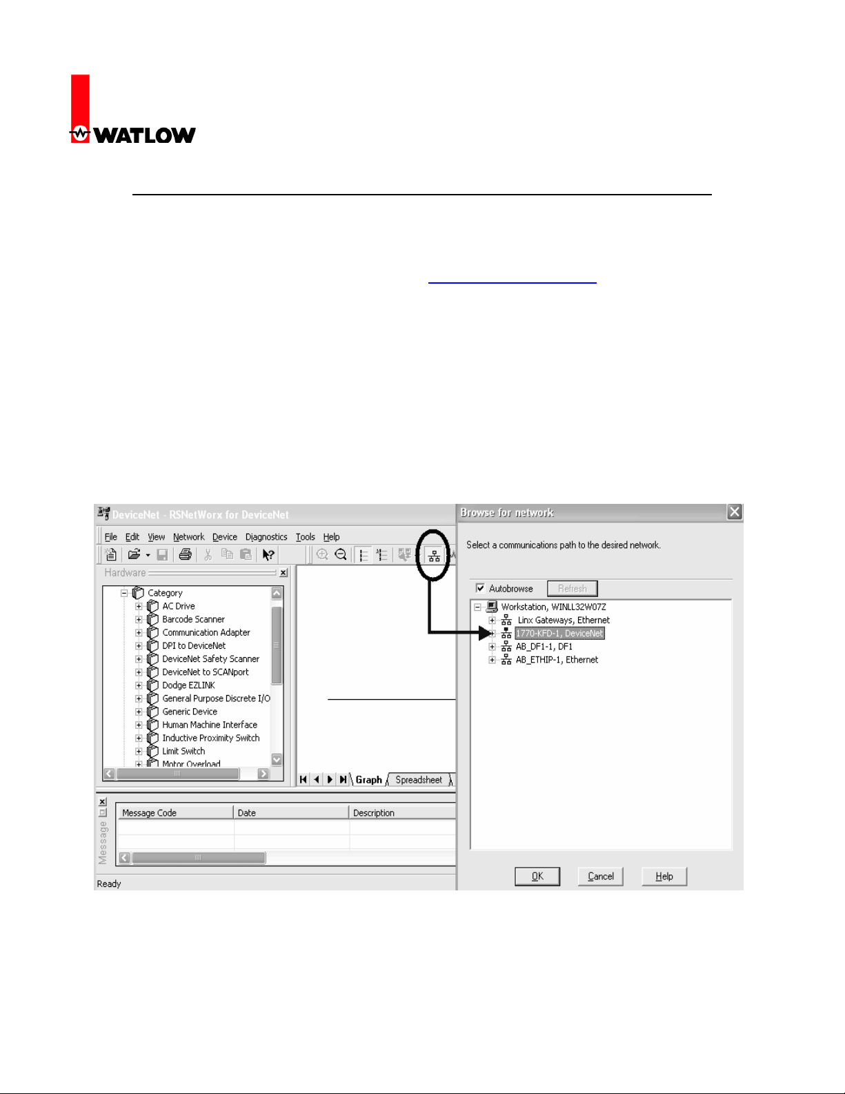
3. As shown below (within RSNetWorx software), click on the online command from the tools
toolbar and then select the appropriate communications path to browse the DeviceNetTM
network. Set up in previous step using RSLinx software.
4. After successfully browsing the network all nodes on the network will appear in the graphical
Watlow
1241 Bundy Blvd
Winona, MN 55987
Telephone: 507-494-5656
© 2007 Watlow Electric Mfg Co 1 4/08
®
PM Communications Manual and follow the procedure defined in the DeviceNet
TM
Using RSNetWorx
TM
are set according to your
TM
RUI/Gateway & DeviceNet
TM
Configuration & Ladder Logic Example
Using an Allen-Bradley CompactLogix PLC
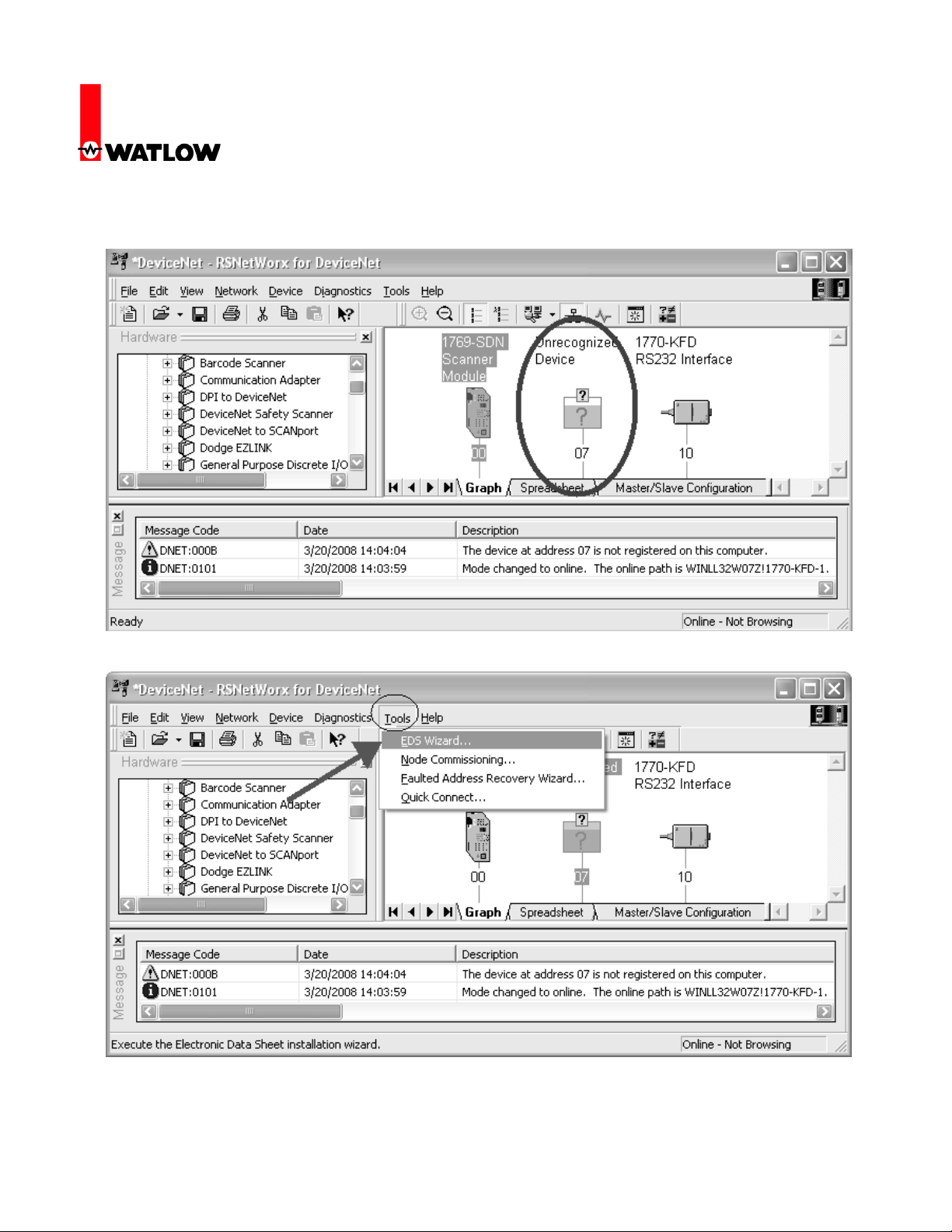
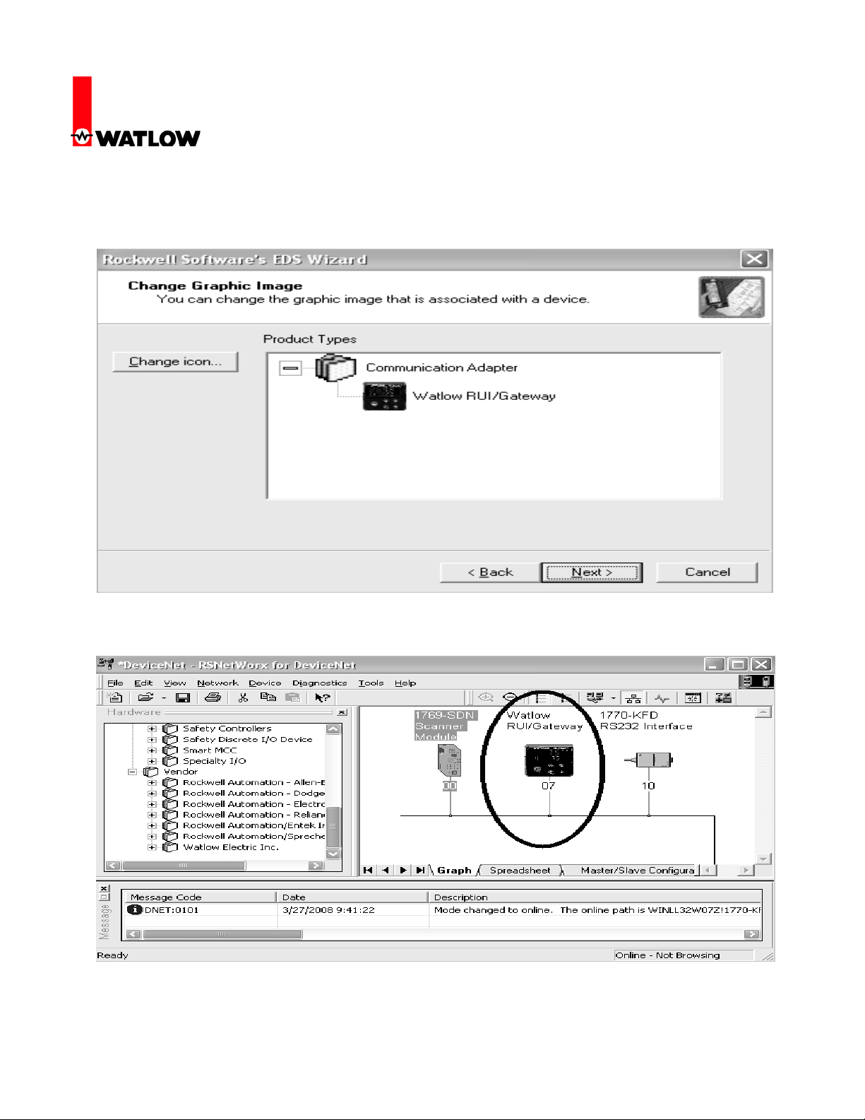
display as shown below. In this particular case, node 7 (RUI/Gateway) appears with a
question mark because it has not yet been registered on the network.
5. To register any given node on the network click on Tools and then EDS Wizard.
Watlow
1241 Bundy Blvd
Winona, MN 55987
Telephone: 507-494-5656
© 2007 Watlow Electric Mfg Co 2 4/08
RUI/Gateway & DeviceNet
TM
Configuration & Ladder Logic Example
Using an Allen-Bradley CompactLogix PLC
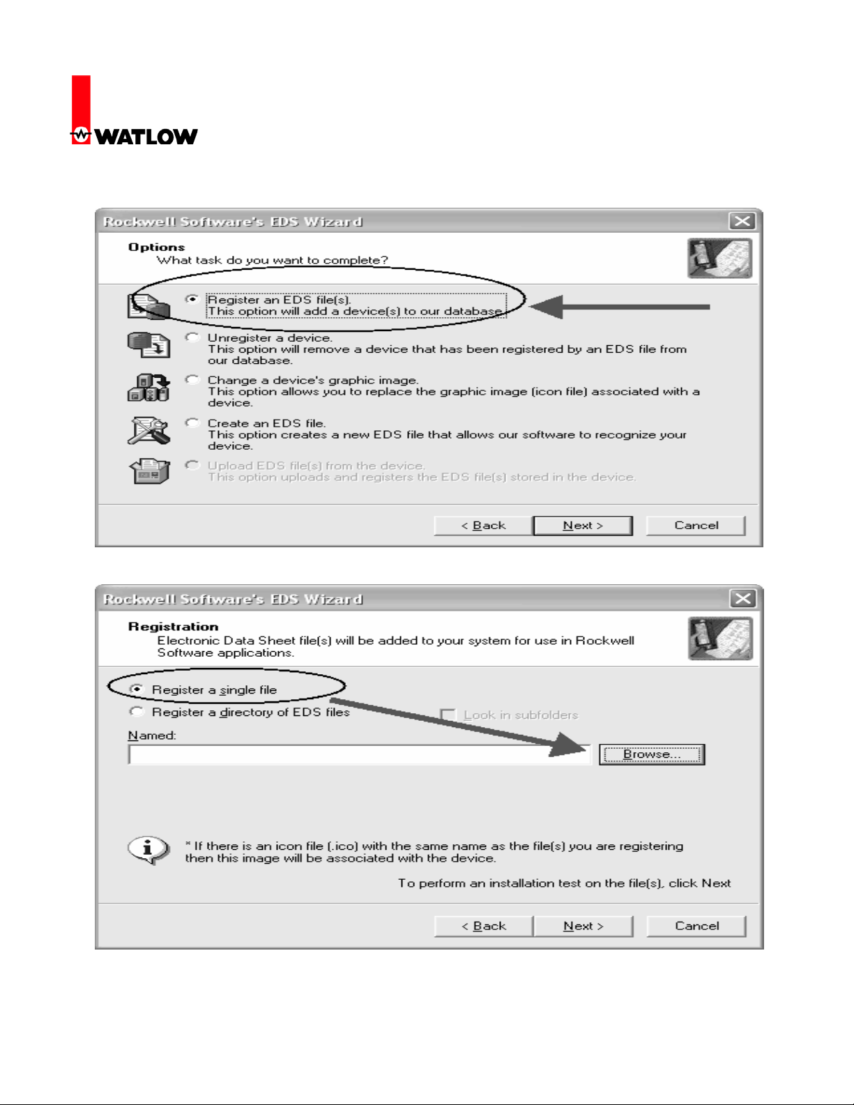
6. Select Register an EDS file.
7. Register a single file and then click browse to locate its location.
Watlow
1241 Bundy Blvd
Winona, MN 55987
Telephone: 507-494-5656
© 2007 Watlow Electric Mfg Co 3 4/08
RUI/Gateway & DeviceNet
TM
Configuration & Ladder Logic Example
Using an Allen-Bradley CompactLogix PLC
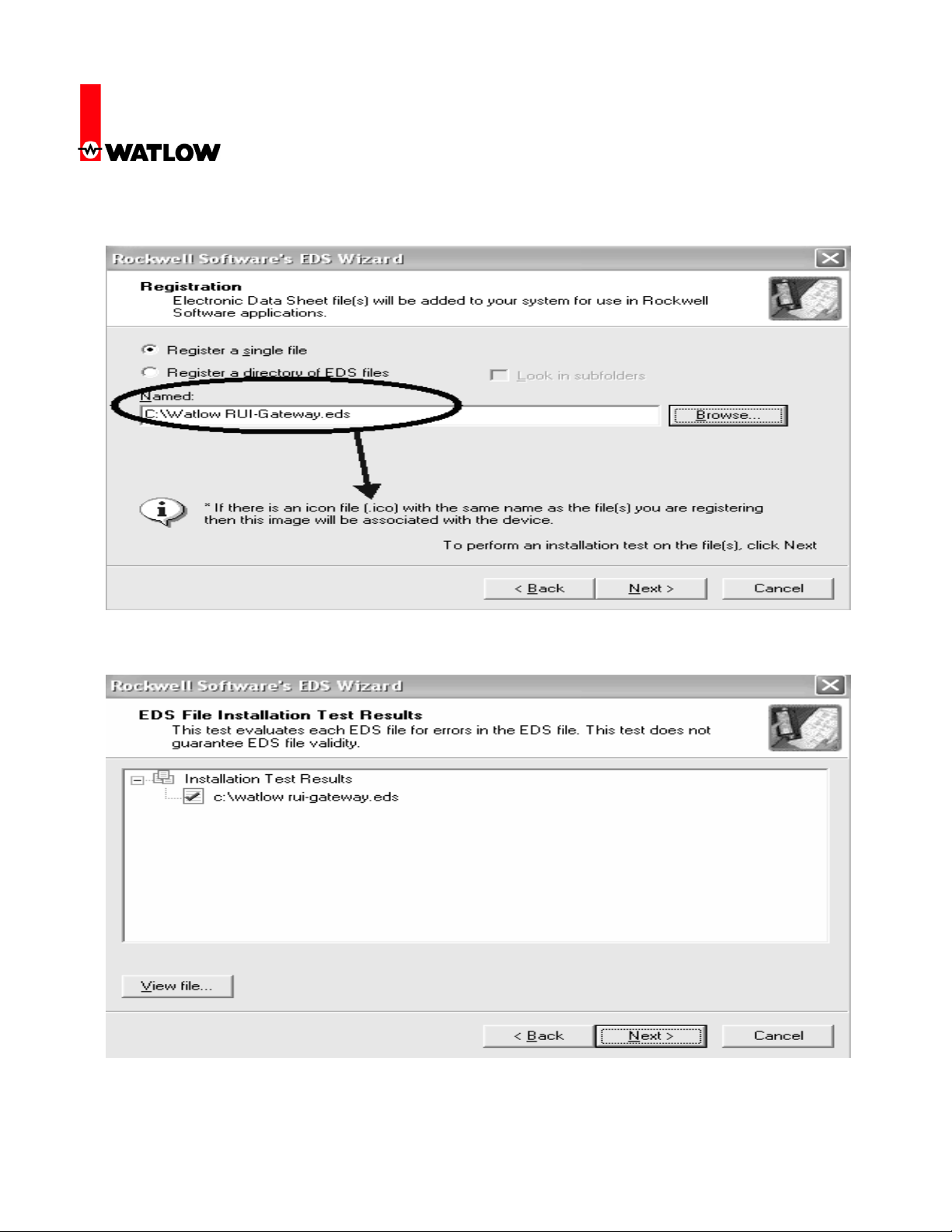
8. When found notice that if there is an icon with the same name the software will register it
along with the EDS file. Click next to proceed with the registration.
9. The next step verifies that there are no errors in the EDS file; a green check should be
displayed next to the file as shown below.
Watlow
1241 Bundy Blvd
Winona, MN 55987
Telephone: 507-494-5656
© 2007 Watlow Electric Mfg Co 4 4/08
RUI/Gateway & DeviceNet
TM
Configuration & Ladder Logic Example
Using an Allen-Bradley CompactLogix PLC
10. After clicking next above, the software will associate an icon to this device, if there was none
found in the previous step it will use a default icon to graphically represent this node. Click
next to proceed.
11. Clicking next above completes the registration process where the question mark is removed
and replaced with the icon of choice for node 7 (Watlow RUI/Gateway).
Watlow
1241 Bundy Blvd
Winona, MN 55987
Telephone: 507-494-5656
© 2007 Watlow Electric Mfg Co 5 4/08
RUI/Gateway & DeviceNet
TM
Configuration & Ladder Logic Example
Using an Allen-Bradley CompactLogix PLC
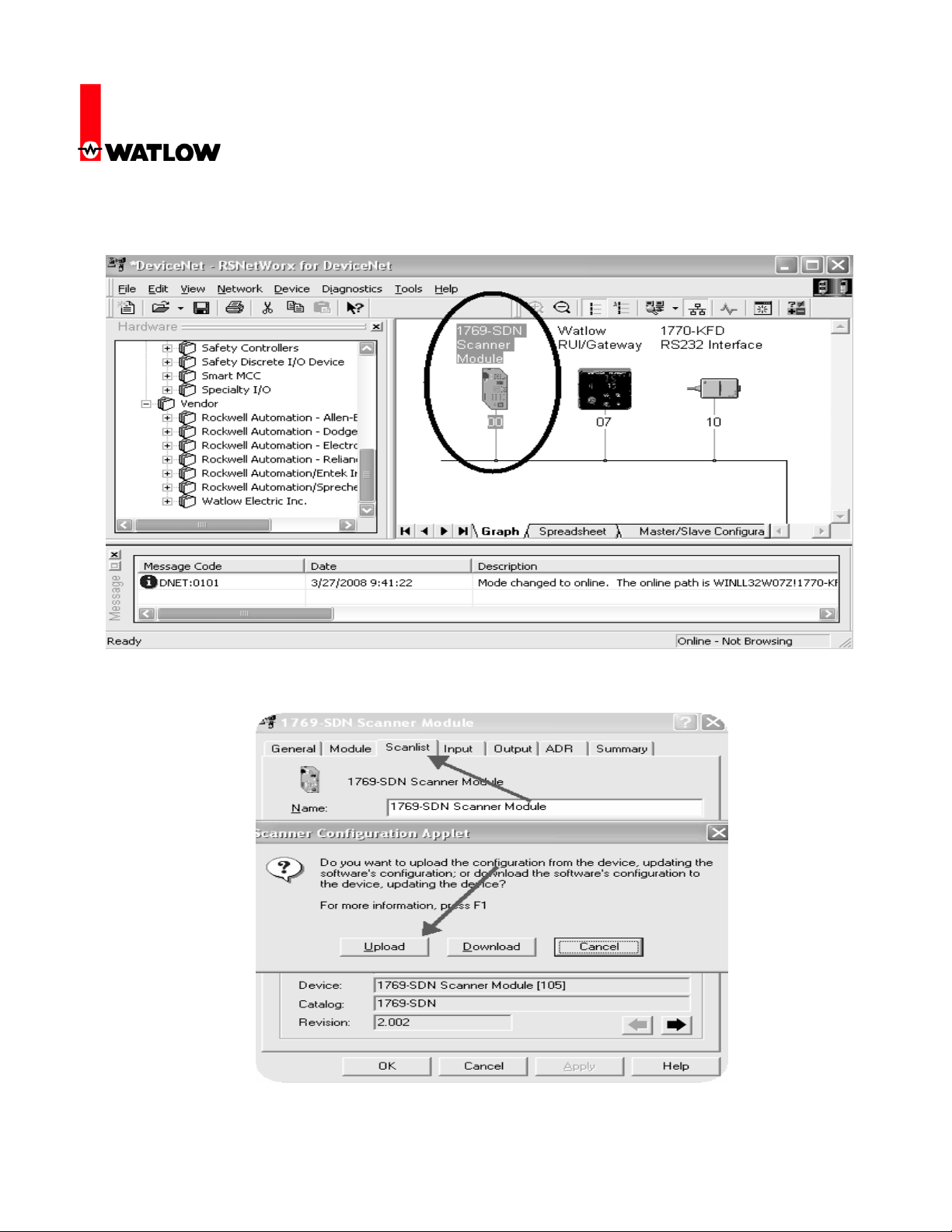
12. The next series of steps involves mapping the available RUI/Gateway input (84) and output
(80) bytes via the scanner into the PLC memory. Double click on the scanner module to
proceed.
13. Click on the scanlist tab where the next dialogue will suggest an upload or a download. Click
on the upload button to allow the scanner to see what is available on the network.
Watlow
1241 Bundy Blvd
Winona, MN 55987
Telephone: 507-494-5656
© 2007 Watlow Electric Mfg Co 6 4/08
RUI/Gateway & DeviceNet
TM
Configuration & Ladder Logic Example
Using an Allen-Bradley CompactLogix PLC
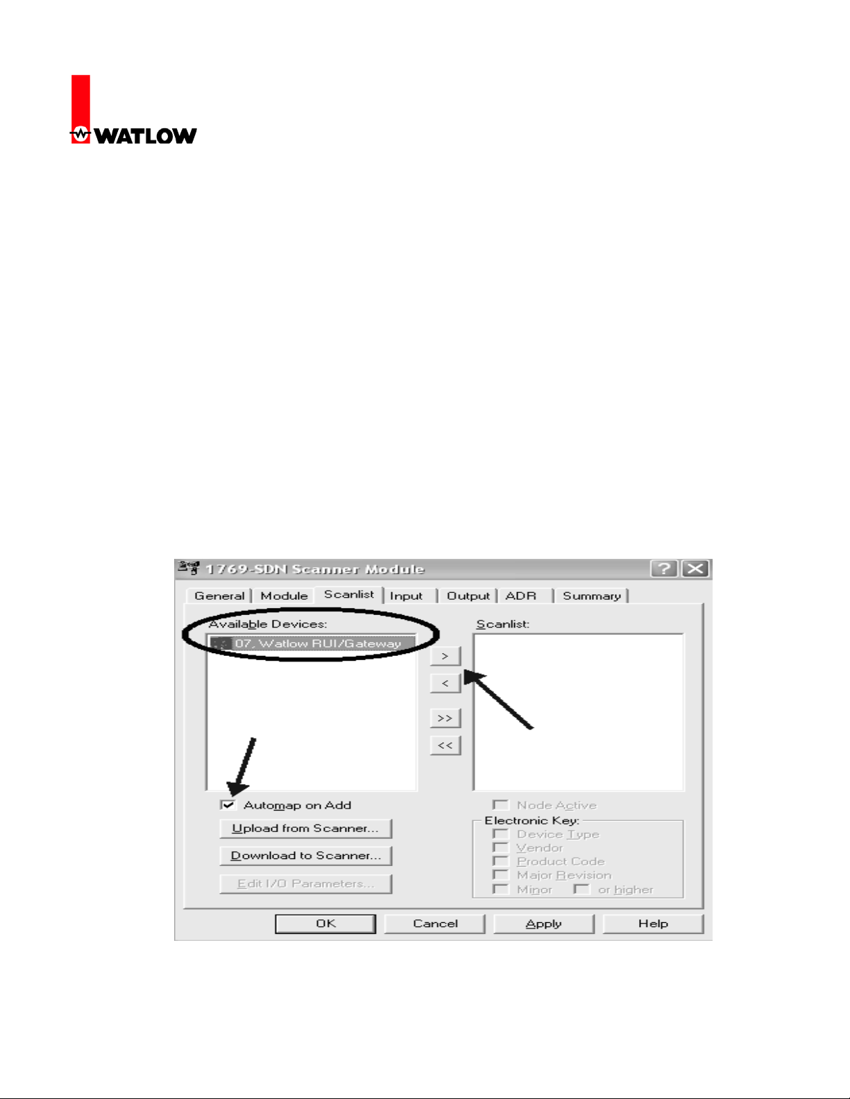
14. After the scanner recognizes the RUI/Gateway on the network it will then appear as an
Available Device as shown below. Before clicking on the right arrow to add it in the scanners
scan list consider the effect of the Automap on Add check box. If this box is checked and
there are other currently existing nodes on the network where they may not be using
complete words (less than 32 bits) the scanner will not consider word boundaries when
adding a new node and will attempt to utilize every available bit in the PLC. As an example, if
a given device has only 9 bytes of information it will use 2¼ 32 bit words (3 bytes not used in
the last word). Now, when adding a new node like the RU/Gateway that utilizes 80 bytes (2032 bit words with each being a separate entity, i.e., 32 bit Set Point) ¾ of the first word will be
placed in the last word of the node mentioned above. The impact of this action would then
break up all of the 20 words sent to and received from the RUI/Gateway in a convoluted way.
For this reason, it is suggested that this box be unchecked (if there are other devices on the
network) allowing the individual doing the configuration to select the appropriate word
boundaries manually.
In this case, there are no other devices on the network so leaving the Automap on Add box
checked will not have a negative impact on the gateway configuration.
Watlow
1241 Bundy Blvd
Winona, MN 55987
Telephone: 507-494-5656
© 2007 Watlow Electric Mfg Co 7 4/08

RUI/Gateway & DeviceNet
TM
Configuration & Ladder Logic Example
Using an Allen-Bradley CompactLogix PLC
15. Once the available device (RUI/Gateway in this case) is moved over to the Scanlist the next
step will be to map the RUI/Gateway input and output bytes to PLC addresses; first the
inputs. In this particular case the Automap on Add box was checked and the result of that now
becomes apparent. Since there were no other devices on the network the software simply
took all of the available RUI/Gateway input bytes (84) and allocated them to the first available
PLC input bytes. Although we can’t see in the graphic below all of the addresses assigned
you can trust that what was assigned are addresses 1:I.Data[0] through 1:I.Data[20]. If there
were other devices on the network and the Automap on Add box was not checked the
address field below would not be populated. Clicking on the Advanced button would then
allow for manual configuration.
16. Likewise, all of what was said above regarding the inputs also applies to the outputs as well.
Notice in the graphic below that for the outputs the size changes to 80 bytes or 20-32 bit
words and addresses given would be 1:O.Data[0] through 1:O.Data[19]. Click on the OK
button where you will then be prompted to write this configuration to the scanner memory.
Watlow
1241 Bundy Blvd
Winona, MN 55987
Telephone: 507-494-5656
© 2007 Watlow Electric Mfg Co 8 4/08

RUI/Gateway & DeviceNet
TM
Configuration & Ladder Logic Example
Using an Allen-Bradley CompactLogix PLC
The PLC will need to be in the program or remote program mode for this to occur. When
written this completes the configuration of the RUI/Gateway using RSNetWorx.
Configuration of the RUI/Gateway
17. Prior to looking at the PLC side of things let’s first take a look at a possible network
configuration. The graphic below depicts a network consisting of an RUI/ Gateway with a PLC
on one side talking DeviceNet
®
ZONE
PM controls talking Standard Bus. Now, seeing the network layout, the next step is to
configure the RUI/Gateway.
TM
where on the other side of the gateway we see four EZ-
Watlow
1241 Bundy Blvd
Winona, MN 55987
Telephone: 507-494-5656
© 2007 Watlow Electric Mfg Co 9 4/08

RUI/Gateway & DeviceNet
TM
Configuration & Ladder Logic Example
Using an Allen-Bradley CompactLogix PLC
18. The table below does not represent all of the RUI/Gateway prompts that need configuration
but they do represent those that are pertinent to this discussion. (For further information on
the RUI/Gateway configuration go to the Watlow website and download the RUI/Gateway
User Manual)
Gateway
Instance
Gtw = 1 Du;en = Yes ost = 0
Gtw = 2 Du;en = Yes ost = 4
Gtw = 3 Du;en = Yes ost = 8
Gtw = 4 Du;en = Yes ost = 12
Enable
Gateway
Instance
CIP
Offset
Watlow
1241 Bundy Blvd
Winona, MN 55987
Telephone: 507-494-5656
© 2007 Watlow Electric Mfg Co 10 4/08

RUI/Gateway & DeviceNet
TM
Configuration & Ladder Logic Example
Using an Allen-Bradley CompactLogix PLC
19. The gateway instance represents the EZ-ZONE
®
control, in this case, PM 1-4. The enable
gateway instance simply turns on that particular gateway where there is a direct correlation
®
between gateway instance 1 and EZ-ZONE
continues through gateway instance 16 and EZ-ZONE
PM controller 1. Likewise, that relationship
®
PM controller 16. The gateway
instance will always equate to the Standard Bus controller with the same address 1-16.
The CIP offset allows for the PLC or any master on the DeviceNetTM side to read or write the
same member from any of the four controllers on the Standard Bus network via an explicit
message.
Configuring the DeviceNetTM Scanner (1769-SDN) Using RSLogix 5000
20. In the examples that follow please note that the PLC being used is a CompactLogix L32E. If
using other PLCs the steps will vary slightly but the overall concepts will be the same. As you
might guess some configuration is required on the PLC side prior to getting started with the
programming.
21. Insert a DeviceNetTM scanner into the I/O structure of the PLC. Notice below the input and
output size correlates directly to what was configured in RSNetWorx (step 15).
Watlow
1241 Bundy Blvd
Winona, MN 55987
Telephone: 507-494-5656
© 2007 Watlow Electric Mfg Co 11 4/08

RUI/Gateway & DeviceNet
TM
Configuration & Ladder Logic Example
Using an Allen-Bradley CompactLogix PLC
22. Notice too, the slot number, in this case “1”. This is the physical slot in which the scanner
resides. After the scanner is configured two tags will be automatically generated reflecting the
existence of the scanner in slot 1 of the I/O structure. These tags will be used to move the
implicit input and output assemblies (more on this to follow) to and from the RUI/Gateway and
then ultimately to the destination EZ-ZONE
®
PM controls that exist on Standard Bus.
EZ-ZONE® EEPROM
23. Before we get started with the programming examples it is important to note that the EZ-
ZONE® family of controls has an on-board EEPROM to back up user settings in the event of
a power loss. By default, the non-volatile save parameter is enabled, therefore changes made
over the network as well as any changes made from the RUI are saved to the EEPROM. If
®
the implicit output (PLC to EZ-ZONE
exchanged implicitly (continuously after the connection is established) the rate at which writes
to EEPROM occur could be very fast. With this being said, it should be considered carefully
as to whether or not this parameter should remain enabled. To avoid premature EEPROM
failure (~1,000,000 writes) it is recommended that the user disable the non-volatile write
parameter in the destination nodes residing on the Standard Bus side of the RUI/Gateway. An
example will follow showing how to read and write to this parameter.
Control) assembly is in use, where information is
Watlow
1241 Bundy Blvd
Winona, MN 55987
Telephone: 507-494-5656
© 2007 Watlow Electric Mfg Co 12 4/08

RUI/Gateway & DeviceNet
TM
Configuration & Ladder Logic Example
Using an Allen-Bradley CompactLogix PLC
Reading and Writing to/from RUI/Gateway Using RSLogix 5000
24. The rung of logic below when enabled, will execute an explicit message sent to the gateway
where it will then be routed out over Standard Bus to the EZ-ZONE
the instance (oSt prompt). Because the CIP offset is set to 12 for gateway instance 4 this
message will be routed to PM4. When done, the destination tag identified under the
configuration tab “EEPROM _Status” (see below) will contain the value of either 106 being
enabled or 59 being disabled.
®
PM control defined by
Watlow
1241 Bundy Blvd
Winona, MN 55987
Telephone: 507-494-5656
© 2007 Watlow Electric Mfg Co 13 4/08

RUI/Gateway & DeviceNet
TM
Configuration & Ladder Logic Example
Using an Allen-Bradley CompactLogix PLC
25. Notice above that there are screen shots for the configuration and communication tabs.
Within the configuration, the programmer will need to specify whether this is a read (Get) or a
write (Set) operation as well as the class, instance, and attribute (CIA) of interest. The CIA for
all PM controls is 150, 2, 8 respectively. The CIA shown above in hexadecimal represents the
Non-Volatile Save parameter for node 4 going through the RUI/Gateway (see step 24 for
explanation). The communication tab allows the programmer to select a configured I/O
module to send or receive the message where the port number and node address need to be
identified. Again, as can be seen above the module is defined in the I/O structure as
DNet_Scanner.
26. If it is desired to write a new value to the member above simply change the service type to set
attribute and define the source element with the new value.
Note:
If attempting to read or write to this parameter (Non-Volatile Save) in the EZ-ZONE® ST the
class, instance, and attribute is different from what is shown above in step 24. For the ST, the
Class = 117, Instance = 1, Attribute = 51. The numbers shown are in decimal where the class
and the attribute will need to be converted to hexadecimal for the message instruction.
27. As another example of explicit messaging, to read a specific member such as PV1 of PM1 as
shown in the graphic above (step 17) the MSG instruction in the PLC would be configured
with the class equal to 104, instance would be 1, and the attribute would be 1 as found in the
EZ-ZONE
network, if it were desired to read the same member from PM3, the MSG instruction would
be configured with the class equal to 104, instance would be 9, and the attribute would be 1.
Because the CIP offset is equal to 8 for gateway instance 3 the gateway will route the
message to PM3, retrieve the first instance of the Analog Input in this case PV1, and then
send it back out to the PLC.
28. As stated in step 22 the RUI/Gateway is equipped with implicit I/O assemblies. The graphics
below represent the I/O default assemblies as shipped from the factory. The T to O input
assembly (Target - Gateway) to (Originator - PLC) consists of twenty one members and the O
to T (Originator - PLC) to (Target - Gateway) consists of twenty members. Again, these
graphics represent the factory defaults for the implicit I/O assemblies. With one exception,
any of the individual members in either assembly can be user programmed. The exception
can be found as the first member of the T to O assembly “Device Status” (more on this to
follow).
®
PM Communications Manual under the Operations Page. On the other end of the
Watlow
1241 Bundy Blvd
Winona, MN 55987
Telephone: 507-494-5656
© 2007 Watlow Electric Mfg Co 14 4/08

RUI/Gateway & DeviceNet
TM
Configuration & Ladder Logic Example
Using an Allen-Bradley CompactLogix PLC
Watlow
1241 Bundy Blvd
Winona, MN 55987
Telephone: 507-494-5656
© 2007 Watlow Electric Mfg Co 15 4/08
Default Target to Originator (T to O) Assembly
Default Originator to Target (O to T) Assembly

RUI/Gateway & DeviceNet
TM
Configuration & Ladder Logic Example
Using an Allen-Bradley CompactLogix PLC
29. Each of the members shown above are passed implicitly to and from the gateway to the PLC
with little to no programming.
Note:
If you are interested in learning more about how to change either of the implicit assemblies
download the PM Communications manual from the Watlow website. Refer to step one for the
link to Watlow’s website.
30. For ease in programming it is suggested (but not necessary) that two user defined data types
be created reflecting the default assembly structures (or the user defined structure) as shown
below. In the examples that follow two user defined data types will be used which correspond
with the network architecture as shown in step 17 for both T to O and O to T assemblies.
Custom O to T Data Type Custom T to O Data Type
Watlow
1241 Bundy Blvd
Winona, MN 55987
Telephone: 507-494-5656
© 2007 Watlow Electric Mfg Co 16 4/08
RUI/Gateway & DeviceNet
TM
Configuration & Ladder Logic Example
Using an Allen-Bradley CompactLogix PLC
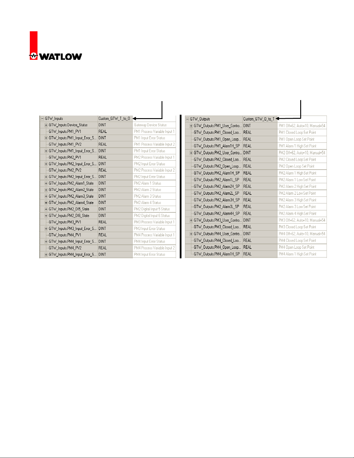
31. Once the user defined data types have been created for the T to O and O to T assemblies
right click on the controller tags folder and add new tags using the T to O and O to T data
types just created; in this case, “Custom_GTW_T_to_O” and “Custom_GTW_O_to_T”.
Controller Tag (T to O)
32. Using the same network architecture as shown in step 17, let’s look closer at the use
of these implicit assemblies. As can be seen above the available 20 members for inputs
and outputs are being distributed across PM1 - PM4 disproportionally. Keep in mind, that the
maximum number of modifiable members for the T to O and O to T assemblies is 20 where
the user can dedicate all of them to one EZ-ZONE
®
PM (*ST excluded) control or distribute
them in any manner across the network. The distribution of the assemblies is determined by
the CIP Assembly size a;nb prompt within the RUI.
* The EZ-ZONE® ST allows for explicit messaging only, it does not allow for implicit
messaging (communications via the I/O assemblies).
33. Look closely at the names and the descriptions of the assemblies in step 31; the assembly
distribution across the four controls on Standard Bus can be seen clearly. Hopefully it is now
clear as to why it is recommended that user defined data types be created and then the
controller tags to utilize those data types. Simply stated, the purpose is to enable easier
Controller Tag (O to T)
Watlow
1241 Bundy Blvd
Winona, MN 55987
Telephone: 507-494-5656
© 2007 Watlow Electric Mfg Co 17 4/08

RUI/Gateway & DeviceNet
TM
Configuration & Ladder Logic Example
Using an Allen-Bradley CompactLogix PLC
transfer of data to and from the PLC and EZ-ZONE
in the PLC. The copy instruction also works nicely when all of the data types are not the same
such as when working with 8 bit, 16 bit, and 32 bit members. The copy instruction copies the
source to the destination byte for byte so there is no further conversion needed.
34. Because there are 4 entries for PM1 in the custom T to O and O to T assemblies above, that
must mean that the CIP Assembly Size for gateway instance 1 is equal to four. Using the
same logic, PM2 has 10 entries so the Assembly Size must be equal to 10, etc…
Gateway
Instance
CIP
Assembly
Size
Gtw = 1 A;nb = 4
Gtw = 2 A;nb = 10
Gtw = 3 A;nb = 2
Gtw = 4 A;nb = 4
As can be seen above, unless changed, the members that occupy any one of the 20 member
locations (or wherever the gateway instance changes) will be according to the factory
defaults. So, the first member of the T to O for any given gateway instance will always be
PV1 regardless of where it is placed in the assembly.
35. The first member of the T to O assembly above is identified as “Device Status “. This member
will always be present and explains why in step 15 that the input assembly size is shown as
84 bytes (21-32 bit words) different from the output assembly being 80 bytes (20-32 bit
words).
To better understand the above status word a couple of important facts related to Standard
Bus addressing must be explained. Lets first look at valid addresses (physical & logical) for
computers, RUIs, Communication cards (Masters, 0-15), and lastly, EZ-ZONE
(Slaves, 16-31). The logical addresses are set by the user. Look at the table below.
®
controllers via simple copy instructions
®
controllers
Watlow
1241 Bundy Blvd
Winona, MN 55987
Telephone: 507-494-5656
© 2007 Watlow Electric Mfg Co 18 4/08

RUI/Gateway & DeviceNet
TM
Configuration & Ladder Logic Example
Using an Allen-Bradley CompactLogix PLC
Device Physical Address Logical Address (Set by User)
Personal Computers 0-3 1-4
RUI 4-11 1-8
Communication Cards 12-15 1-4 (indirectly set by user)
EZ-ZONE
®
Controllers 16-31 1-16
The first graphic in step 35 shows the first member of the custom T to O assembly
“GTW_Inputs.Device_Status”. Interpreting the bits…bit 0 is shown on the far right where bit
31 is on the far left. The bits that are shown as being set to a “1” represent those devices that
the RUI/Gateway is enabled to speak to (Gateway instance). So, bit 16 through 19 represents
the PM controls on the Standard Bus side of the RUI/Gateway (1 - 4, as seen in step 17)
where bit 12 represents the physical address for the DeviceNetTM card in the RUI/Gateway.
Each of these bits can be monitored in the PLC where an alarm can be driven if communications with any enabled PM control fails.
36. Note that in the table above (step 35) showing both logical and physical addresses (logical
addresses are set by the user) that the communications card addressing is not set directly by
the user. To relieve the burden of having to set multiple Standard Bus addresses in the
RUI/Gateway the communication card picks up its address through the RUI/Gateway firmware. If the RUI/Gateway Standard Bus address (with a comms card installed) is set to logical
address 1 the communications card Standard Bus physical address will automatically be set
12. See table below for valid communications card addressing. As can be seen below, if the
communications card is to be given a valid address the RUI/Gateway logical address must be
set to a value ranging from 1-4.
RUI/Gateway Addressing Communications Card
Standard Bus
Physical Address
Logical Address
(Set by User)
Physical Address
4 1 12
5 2 13
6 3 14
7 4 15
8 5 Not Valid
9 6 Not Valid
10 7 Not Valid
11 8 Not Valid
Watlow
1241 Bundy Blvd
Winona, MN 55987
Telephone: 507-494-5656
© 2007 Watlow Electric Mfg Co 19 4/08

RUI/Gateway & DeviceNet
TM
Configuration & Ladder Logic Example
Using an Allen-Bradley CompactLogix PLC
37. In step 30 it was suggested that the user may want to create user defined data types.
Likewise, in step 31 it was also suggested that the user should create controller tags utilizing
those same user defined data types. The reasoning for this may become more obvious in the
following example. Below, two copy instructions are programmed to send and receive the
implicit assemblies to/from the PLC to the desired EZ-ZONE
38. As can be seen above the controller tags created for inputs from the EZ-ZONE
the PLC was defined as “GTW_Inputs” where the tag created for the outputs from PLC to EZZONE
®
controls was named “GTW_Outputs”. The ease in programming should now be
apparent. Due to the fact that the user defined data types for both T to O and O to T
assemblies where defined to correlate directly to the specific EZ-ZONE
the transfer of data between EZ-ZONE
®
controls and the PLC is done without a lot of effort.
Below the two graphics represent both the T to O and O to T assemblies with live data.
Watlow
1241 Bundy Blvd
Winona, MN 55987
Telephone: 507-494-5656
© 2007 Watlow Electric Mfg Co 20 4/08
®
controls.
®
controls to
®
members of choice

RUI/Gateway & DeviceNet
TM
Configuration & Ladder Logic Example
Using an Allen-Bradley CompactLogix PLC
Custom T to O Assembly
Custom O to T Assembly
Watlow
1241 Bundy Blvd
Winona, MN 55987
Telephone: 507-494-5656
© 2007 Watlow Electric Mfg Co 21 4/08
 Loading...