

Watlow Electric EZ-ZONE PM User Manual
ISO 9001
CUSTTOOMMERER
TISFAA
CTIOONN
EZ-ZONE® PM
User’s Manual
0600-0059-0000 Rev. C Made in the U.S.A.
March 2008 $15.00
Integrated Controller Models
1241 Bundy Boulevard., Winona, Minnesota USA 55987
Phone: +1 (507) 454-5300, Fax: +1 (507) 452-4507 http://www.watlow.com
TOTAL
CUS
SSAATISF
3 Year Warranty
ISO 9001
Registered Company
Winona, Minnesota USA
CTI

Safety Information
We use note, caution and warning symbols throughout this book to draw your attention to important
operational and safety information.
A “NOTE” marks a short message to alert you to
an important detail.
A “CAUTION” safety alert appears with information that is important for protecting your equipment and performance. Be especially careful to
read and follow all cautions that apply to your
application.
A “WARNING” safety alert appears with information that is important for protecting you,
others and equipment from damage. Pay very
close attention to all warnings that apply to your
application.
The safety alert symbol, ç (an exclamation
point in a triangle) precedes a general CAUTION
or WARNING statement.
The electrical hazard symbol, Ó (a lightning bolt
in a triangle) precedes an electric shock hazard
CAUTION or WARNING safety statement.
ç CAUTION or WARNING
Ó Electrical Shock Hazard
CAUTION or WARNING
Warranty
The EZ-ZONE® PM is manufactured by ISO
9001-registered processes and is backed by a threeyear warranty to the first purchaser for use, providing that the units have not been misapplied. Since
Watlow has no control over their use, and sometimes misuse, we cannot guarantee against failure.
Watlow’s obligations hereunder, at Watlow’s option,
are limited to replacement, repair or refund of purchase price, and parts which upon examination prove
to be defective within the warranty period specified.
This warranty does not apply to damage resulting
from transportation, alteration, misuse or abuse. The
purchaser must use Watlow parts to maintain all
listed ratings.
Technical Assistance
If you encounter a problem with your Watlow controller, review your configuration information to verify
that your selections are consistent with your application: inputs, outputs, alarms, limits, etc. If the problem persists, you can get technical assistance from
your local Watlow representative (see back cover), by
e-mailing your questions to wintechsupport@watlow.
com or by dialing +1 (507) 494-5656 between 7 a.m.
and 5 p.m., Central Standard Time (CST). Ask for for
an Applications Engineer. Please have the following
information available when calling:
• Complete model number
• All configuration information
• User’s Manual
• Factory Page
Return Material Authorization (RMA)
1. Call Watlow Customer Service, (507) 454-5300,
for a Return Material Authorization (RMA) number before returning any item for repair. If you
do not know why the product failed, contact an
Application Engineer or Product Manager. All
RMA’s require:
• Ship-to address
• Bill-to address
• Contact name
• Phone number
• Method of return shipment
• Your P.O. number
• Detailed description of the problem
• Any special instructions
• Name and phone number of person returning
the product.
2. Prior approval and an RMA number from the
Customer Service Department is required when
returning any product for credit, repair or evaluation. Make sure the RMA number is on the outside of the carton and on all paperwork returned.
Ship on a Freight Prepaid basis.
3. After we receive your return, we will examine it
and try to verify the reason for returning it.
4. In cases of manufacturing defect, we will enter a
repair order, replacement order or issue credit for
material returned. In cases of customer mis-use,
we will provide repair costs and request a purchase order to proceed with the repair work.
5. To return products that are not defective, goods
must be be in new condition, in the original boxes
and they must be returned within 120 days of
receipt. A 20 percent restocking charge is applied
for all returned stock controls and accessories.
6. If the unit is unrepairable, you will receive a letter of explanation. and be given the option to have
the unit returned to you at your expense or to
have us scrap the unit.
7. Watlow reserves the right to charge for no trouble
found (NTF) returns.
The EZ-ZONE® PM User’s Manual is copyrighted
by Watlow Winona, Inc., © July 2007 with all rights
reserved.
EZ-ZONE® PM is covered by U.S. Patent No.
6,005,577 and Patents Pending

TC
Table of Contents
Chapter 1: Overview . . . . . . . . . . . . . . . . . . . . . . . . . . . . . . . . . . . . .2
Standard Features and Benefits . . . . . . . . . . . . . . . . . . . . . . . . . . . . . . . 2
Chapter 2: Install and Wire . . . . . . . . . . . . . . . . . . . . . . . . . . . . . . . . .8
Chapter 3: Keys and Displays . . . . . . . . . . . . . . . . . . . . . . . . . . . . . . 24
Attention Codes . . . . . . . . . . . . . . . . . . . . . . . . . . . . . . . . . . . . . . . . . . 24
Chapter 4: Home Page . . . . . . . . . . . . . . . . . . . . . . . . . . . . . . . . . . . 26
Chapter 5: Operations Page . . . . . . . . . . . . . . . . . . . . . . . . . . . . . . . 28
Chapter 6: Setup Page . . . . . . . . . . . . . . . . . . . . . . . . . . . . . . . . . . . 33
Chapter 7: Profiling Page . . . . . . . . . . . . . . . . . . . . . . . . . . . . . . . . . 45
Chapter 8: Factory Page . . . . . . . . . . . . . . . . . . . . . . . . . . . . . . . . . . 49
Chapter 9: Features . . . . . . . . . . . . . . . . . . . . . . . . . . . . . . . . . . . . . 53
Chapter 10: Appendix . . . . . . . . . . . . . . . . . . . . . . . . . . . . . . . . . . .66
Troubleshooting Alarms, Errors and Control Issues . . . . . . . . . . . . . . 66
Specifications . . . . . . . . . . . . . . . . . . . . . . . . . . . . . . . . . . . . . . . . . . . . 69
Ordering Information for Integrated Controller Models . . . . . . . . . . . . 71
Index . . . . . . . . . . . . . . . . . . . . . . . . . . . . . . . . . . . . . . . . . . . . . . . . . . . 72
Declaration of Conformity . . . . . . . . . . . . . . . . . . . . . . . . . . . . . . . . . . . 76
Watlow EZ-ZONE® PM Integrated Controller • 1 • Table of Contents

1
Chapter 1: Overview
The EZ-ZONE® PM takes the pain out of solving
your thermal loop requirements.
Watlow ’s E Z -Z ONE® PM controllers offer options
to reduce system complexity and the cost of controlloop ownership. You can order the EZ-ZONE® PM as
a PID controller or an over-under limit controller, or
you can combine both functions in the PM Integrated Limit Controller. You now have the option to integrate a high-amperage power controller output, an
over-under limit controller and a high-performance
PID controller all in space-saving, panel-mount
packages. You can also select from a number of serial communications options to help you manage system performance.
It just got a whole lot easier to solve the thermal requirements of your system. Because the EZZONE® PM controllers are highly scalable, you only
pay for what you need. So if you are looking for a
PID controller, an over-under limit controller or an
integrated controller, the EZ-ZONE® PM is the answer.
Standard Features and Benefits
Advanced PID Control Algorithm
• TRU-TUNE+® Adaptive tune provides tighter con-
trol for demanding applications.
• Auto Tune for fast, efficient start ups
Agency approvals: UL Listed, CSA, CE, RoHS,
W.E.E.E. FM
• Assures prompt product acceptance
• Reduces end product documentation costs
• FM approval on Limit Models
• Semi F47-0200
P3T Armor Sealing System
• NEMA 4X and IP66 offers water and dust resis-
tance, can be cleaned and washed down
• Backed up by UL 50 independent certification to
NEMA 4X specification
Three-year warranty
• Demonstrates Watlow’s reliability and product
support
Touch-safe Package
• IP2X increased safety for installers and operators
Removable cage clamp wiring connectors
• Reliable wiring, reduced service calls
• Simplified installation
EZ-Key
• Programmable EZ-Key enables simple one-touch
operation of repetitive user activities
High-amperage Power Control Output
• Drives 15 amp resistive loads directly
• Reduces component count
• Saves panel space and simplifies wiring
• Reduces the cost of ownership
EZ-ZONE® configuration communications and
software
• Saves time and improves the reliability of control-
ler set up
FM Approved Over-under Limit with Auxiliary
Outputs
• Increases user and equipment safety for over-
under temperature conditions
Parameter Save & Restore Memory
• Reduces service calls and down time
Watlow EZ-ZONE® PM Integrated Controller • 2 • Chapter 1 Overview
Programmable Menu System
• Reduces set up time and increases operator effi-
ciency
Full-featured Alarms
• Improves operator recognition of system faults
• Control of auxiliary devices
Heat-Cool Operation
• Provides application f lexibility with accurate tem-
perature and process control
Profile Capability
• Preprogrammed process control
• Ramp and soak programming with four files and
40 total steps

A Conceptual View of the PM
The flexibility of the PM’s software and hardware allows a large range of configurations. Acquiring a better understanding of the controller’s overall functionality and capabilities while at the same time planning out how the controller can be used will deliver
maximum effectiveness in your application.
It is useful to think of the controller in three
parts: inputs; procedures; and outputs. Information
flows from an input to a procedure to an output when
the controller is properly configured. A single PM
controller can carry out several procedures at the
same time, for instance closed-loop control, monitoring for several different alarm situations and operating switched devices, such as lights and motors.
Each process needs to be thought out carefully and
the controller’s inputs, procedures and outputs set up
properly.
Inputs
The inputs provide the information that any given
programmed procedure can act upon. In a simple
form, this information may come from an operator
pushing a button or as part of a more complex procedure it may represent a remote set point being received from another controller.
Each analog input typically uses a thermocouple
or RTD to read the temperature of something. It can
also read volts, current or resistance, allowing it to
use various devices to read humidity, air pressure,
operator inputs and others values. The settings in
the Analog Input Menu (Setup Page) for each analog
input must be configured to match the device connected to that input.
Each digital input reads whether a device is active
or inactive. A PM with digital input-output hardware
includes two sets of terminals each of which can be
used as either an input or an output. Each pair of
terminals must be configured to function as either
an input or output with the Direction parameter in
the Digital Input/Output Menu (Setup Page).
The Function or EZ Key on the front panel of the
PM also operates as a digital input by toggling the
function assigned to it in the Digital Input Function
parameter in the Function Key Menu (Setup Page).
Keep in mind that a function is a user-programmed internal process that does not execute any
action outside of the controller. To have any effect
outside of the controller, an output must be configured to respond to a function.
Outputs
Outputs can perform various functions or actions in
response to information provided by a function, such
as operating a heater; turning a light on or off; unlocking a door; or turning on a buzzer.
Assign an output to a Function in the Output
Menu or Digital Input/Output Menu. Then select
which instance of that function will drive the selected output. For example, you might assign an output
to respond to alarm 4 (instance 4) or to retransmit
the value of analog input 2 (instance 2).
You can assign more than one output to respond
to a single instance of a function. For example, alarm
2 could be used to trigger a light connected to output
1 and a siren connected to digital output 5.
Input Events and Output Events
Input events are internal states that are set by the
digital inputs. Digital input 5 provides the state of
input event 1, and digital input 6 provides the state
of input event 2. Wait for Event steps in profiles
are triggered by these events. The setting of Digital
Input Function (Setup Page, Digital Input/Output
Menu) does not change the relationship between the
input and the event, so take care not to configure the
function in a way that would conflict with a profile
that uses an input event. An input will still control
the input event state, even if Digital Input Function
is set to None.
Output events are internal states that can only be
set by profile steps. Outputs 1 through 4 can be configured to respond to output events.
Functions
Functions use input signals to calculate a value. A
function may be as simple as reading a digital input
to set a state to true or false, or reading a temperature to set an alarm state to on or off. Or, it could
compare the temperature of a process to the set point
and calculate the optimal power for a heater.
To set up a function, it’s important to tell it what
source, or instance, to use. For example, an alarm
may be set to respond to either analog input 1 or 2
(instance 1 or 2, respectively).
Watlow EZ-ZONE® PM Integrated Controller • 3 • Chapter 1 Overview
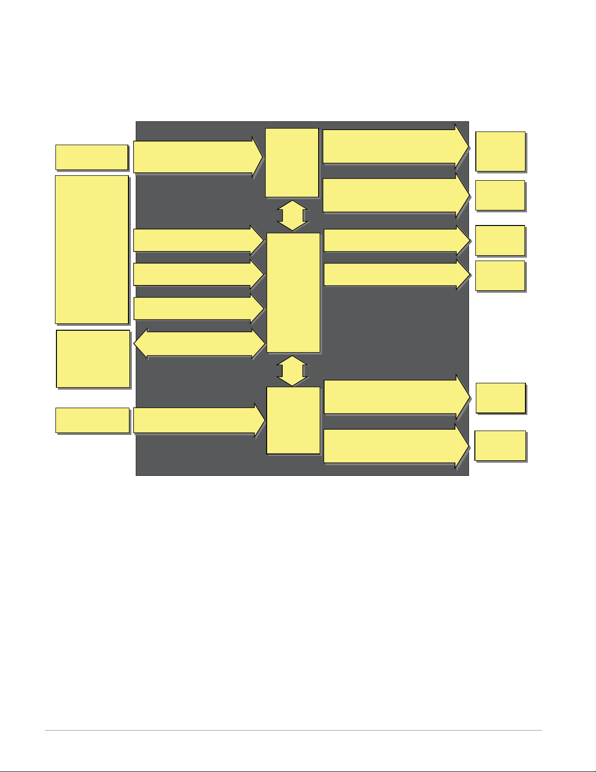
EZ-ZONE® PM Integrated Model 1/16 DIN with a Current Transformer — Input/Output
(no communications options 2 to 3)
Universal Sensor Input, Configuration Communications,
Red/Green 7-Segment Display
Input
Functions
input sensor
none,
idle set point,
alarm reset,
tune,
silence alarm,
manual/auto mode,
control outputs off,
lock keypad,
force alarm,
TRU-TUNE+
loop & alarms off,
profile disable,
profile hold/resume,
profile start,
profile start/stop,
restore user settings
Network
remote user interface,
personal computer,
programmable logic
controller, humanmachine interface
current transformer
®
disable
Analog Input 1 thermocouple,
RTD, process (V, mV, mA, 1k potentiometer)
Digital Input (or Output) 5
(optional) none, switch, volts dc
Digital Input (or Output) 6
(optional) none, switch, volts dc
EZ Key
programmable event
EIA 485 Communications
Standard Bus, Modbus RTU (optional)
Analog Input 2
current transformer
PID
Controller
Board
Slot A
ramp-soak
with 4 files
(optional)
Supervisory
&
Power
Board
Slot C
Current
Transformer
Board
(optional)
Slot B
Output 1 none, switched dc/open
collector, form C mechanical (5 A) or
solid-state (0.5 A) relay, process (V, mA)
Output 2 none, switched dc, no-arc
power control (15 A), form A mechanical
(5 A) or solid-state (0.5 A) relay
Digital Output (or Input) 5 (optional)
none, switched dc
Digital Output (or Input) 6 (optional)
none, switched dc
Output 3 none, switched dc/open
collector, form C mechanical (5 A) or
solid-state (0.5 A) relay, process (V, mA)
Output 4 none, switched dc, form A
mechanical (5 A) or solid-state (0.5 A)
relay
Output
Functions
off, heat, cool,
duplex, alarm,
retransmit,
event
off, heat, cool,
alarm, event
off, heat, cool,
alarm, event
off, heat, cool,
alarm, event
off, heat, cool,
alarm, event,
retransmit
off, heat, cool,
alarm, event
Current Monitoring
• detects heater current f low
• provides an alarm indication of a failed-load issue.
Watlow EZ-ZONE® PM Integrated Controller • 4 • Chapter 1 Overview
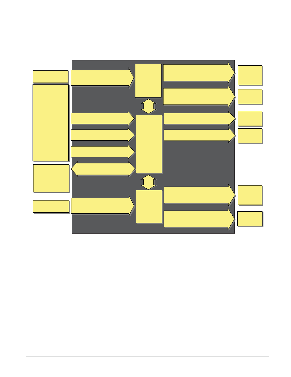
EZ-ZONE® PM Integrated Model 1/16 DIN with Remote Set Point — Input/Output
(no communications options 2 to 3)
Universal Sensor Input, Configuration Communications,
Red/Green 7-Segment Display
Input
Functions
input sensor
none,
idle set point,
alarm reset,
tune,
silence alarm,
manual/auto mode,
control outputs off,
local-remote,
lock keypad,
force alarm,
TRU-TUNE+
loop & alarms off,
profile disable,
profile hold/resume,
profile start,
profile start/stop,
restore user settings
Network
remote user interface,
personal computer,
programmable logic
controller, humanmachine interface
input sensor
®
disable
Analog Input 1 thermocouple,
RTD, process (V, mV, mA, 1k potentiometer)
Digital Input (or Output) 5
(optional) none, switch, volts dc
Digital Input (or Output) 6
(optional) none, switch, volts dc
EZ Key
programmable event
EIA 485 Communications
Standard Bus, Modbus RTU (optional)
Analog Input 2 thermocouple,
RTD, process (V, mV, mA, 1k potentiometer)
PID
Controller
Board
Slot A
ramp-soak
with 4 files
(optional)
Supervisory
&
Power
Board
Slot C
Remote Set
Point
Board
(optional)
Slot B
Output 1 none, switched dc/open
collector, form C mechanical (5 A) or
solid-state (0.5 A) relay, process (V, mA)
Output 2 none, switched dc, no-arc
power control (15 A), form A mechanical
(5 A) or solid-state (0.5 A) relay
Digital Output (or Input) 5 (optional)
none, switched dc
Digital Output (or Input) 6 (optional)
none, switched dc
Output 3 none, switched dc/open
collector, form C mechanical (5 A) or
solid-state (0.5 A) relay, process (V, mA)
Output 4 none, switched dc, form A
mechanical (5 A) or solid-state (0.5 A)
relay
Output
Functions
off, heat, cool,
duplex, alarm,
retransmit,
event
off, heat, cool,
alarm, event
off, heat, cool,
alarm, event
off, heat, cool,
alarm, event
off, heat, cool,
duplex, alarm,
retransmit,
event
off, heat, cool,
alarm, event
Remote Set Point Operation
• Supports efficient set point manipulation from a remote device, such as a master control or PLC.
Watlow EZ-ZONE® PM Integrated Controller • 5 • Chapter 1 Overview
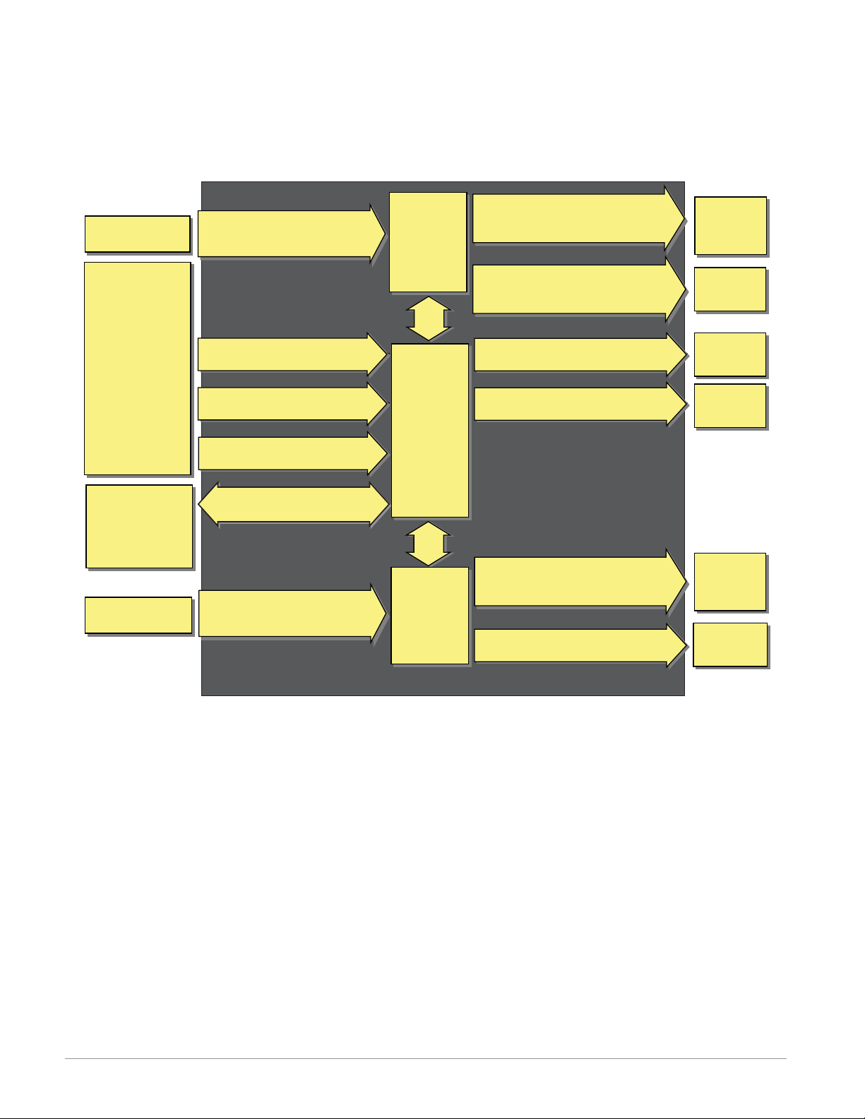
EZ-ZONE® PM Integrated Model 1/16 DIN with a Limit — Input/Output
(no communications options 2 to 3)
Universal Sensor Input, Configuration Communications,
Red/Green 7-Segment Display
Input
Functions
input sensor
none, limit reset,
idle set point,
tune,
alarm reset,
silence alarm,
manual/auto mode,
control outputs off,
lock keypad,
force alarm,
TRU-TUNE+
loop & alarms off,
profile disable,
profile hold/resume,
profile start,
profile start/stop,
restore user settings
Network
remote user interface,
personal computer,
programmable logic
controller, humanmachine interface
input sensor
®
disable
Analog Input 1 thermocouple,
RTD, process (V, mV, mA, 1k potentiometer)
Digital Input (or Output) 5
(optional) none, switch, volts dc
Digital Input (or Output) 6
(optional) none, switch, volts dc
EZ Key
programmable event
EIA 485 Communications
Standard Bus, Modbus RTU (optional)
Analog Input 2 thermocouple,
RTD, process (V, mV, mA, 1k potentiometer)
PID
Controller
Board
Slot A
ramp-soak
with 4 files
(optional)
Supervisory
&
Power
Board
Slot C
Limit
Controller
Board
(optional)
Slot B
Output 1 none, switched dc/open
collector, form C mechanical (5 A) or
solid-state (0.5 A) relay, process (V, mA)
Output 2 none, switched dc, no-arc
power control (15 A), form A mechanical
(5 A) or solid-state (0.5 A) relay
Digital Output (or Input) 5 (optional)
none, switched dc
Digital Output (or Input) 6 (optional)
none, switched dc
Output 3 none, switched dc/open
collector, form C mechanical (5 A) or
solid-state (0.5 A) relay, process (V, mA)
Output 4
form A mechanical (5 A) relay
Output
Functions
off, heat, cool,
duplex, alarm,
retransmit,
event
off, heat, cool,
alarm, event
off, heat, cool,
alarm, event
off, heat, cool,
alarm, event
off, heat, cool,
duplex, alarm,
retransmit,
event, limit
limit
Integrated PID and Limit Controller
• Reduces wiring time and termination complexity compared to connecting separate products
• Reduces panel space
• Reduces installation costs
• Increases dependability with backup control sensor operation
• Increases user and equipment safety for over-under temperature conditions
Watlow EZ-ZONE® PM Integrated Controller • 6 • Chapter 1 Overview

EZ-ZONE® PM Integrated Model 1/16 DIN with Expanded Communications
— Input/Output
Universal Sensor Input, Configuration Communications,
Red/Green 7-Segment Display
Input
Functions
input sensor
none,
idle set point,
tune,
alarm reset,
silence alarm,
manual/auto mode,
control outputs off,
lock keypad,
force alarm,
TRU-TUNE+
loop & alarms off,
profile disable,
profile hold/resume,
profile start,
profile start/stop,
restore user settings
Network
remote user interface,
personal computer,
programmable logic
controller, humanmachine interface
®
disable
Analog Input 1 thermocouple,
RTD, process (V, mV, mA, 1k potentiometer)
Digital Input (or Output) 5
(optional) none, switch, volts dc
Digital Input (or Output) 6
(optional) none, switch, volts dc
EZ Key
programmable event
EIA
485 Communications
Standard Bus, Modbus RTU (optional)
Communications
EIA-232/485 Modbus RTU,
EtherNet/IP
TM
, Modbus TCP
PID
Controller
Board
Slot A
ramp-soak
with 4 files
(optional)
Supervisory
&
Power
Board
Slot C
Communi-
cations
Board
(optional)
Slot B
Output 1 none, switched dc/open
collector, form C mechanical (5 A) or
solid-state (0.5 A) relay, process (V, mA)
Output 2 none, switched dc, no-arc
power control (15 A), form A mechanical
(5 A) or solid-state (0.5 A) relay
Digital Output (or Input) 5 (optional)
none, switched dc
Digital Output (or Input) 6 (optional)
none, switched dc
Output
Functions
off, heat, cool,
duplex, alarm,
retransmit,
event
off, heat, cool,
alarm, event
off, heat, cool,
alarm, event
off, heat, cool,
alarm, event
Serial Communication Capabilities
• Supports network connectivity to a PC or PLC
• Available in a wide range of protocol choices, including Modbus RTU, EtherNet/IP™, Modbus TCP
Watlow EZ-ZONE® PM Integrated Controller • 7 • Chapter 1 Overview
2
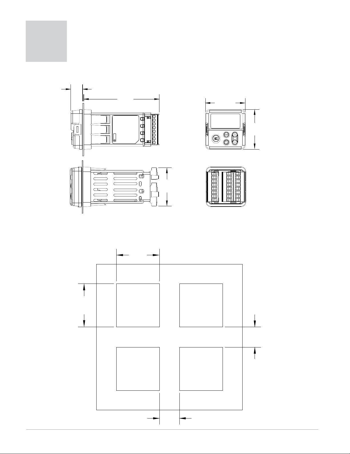
Dimensions
Chapter 2:
Install and Wire
15.8 mm
(0.62 in)
101.6 mm
(4.00 in)
53.3 mm
(2.10 in)
53.3 mm
(2.10 in)
45.2 mm
(1.78 in)
Side
51.2 mm
(2.02 in)
Top Back
Front
L1
K1
J1
L2
K2
T1
S1
R1
45.2 mm
(1.78 in)
Recommended panel spacing
L3
K3
J3
L4
K4
T2
S2
R2
98
99
CF
CD
CE
B5
D6
D5
panel thickness 1.53 to 9.52 mm
(0.060 to 0.375)
21.6 mm
(0.85 in)
21.6 mm
(0.85 in)
Watlow EZ-ZONE® PM Integrated Controller • 8 • Chapter 2 Install and Wire
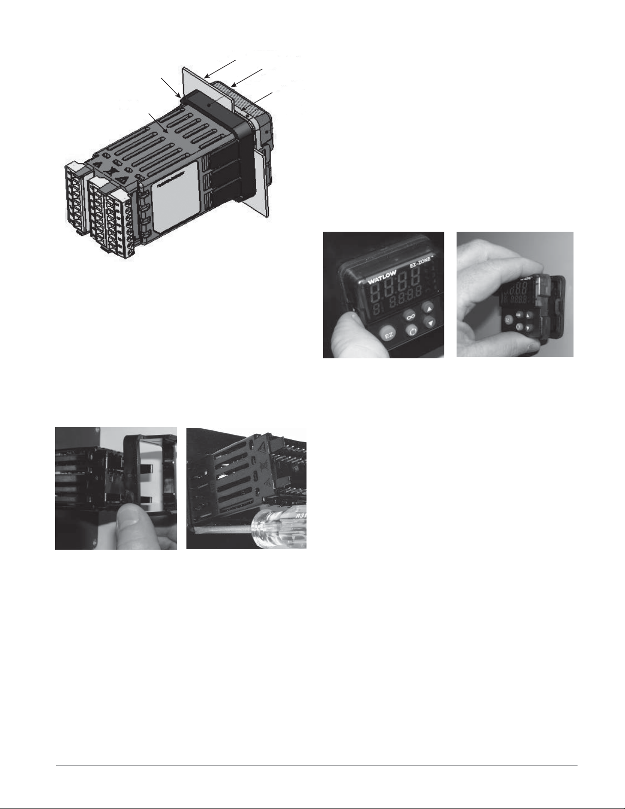
Installation
retention collar
panel
bezel
gasket
The tabs on each side of the mounting collar have
teeth that latch into the ridges on the sides of the
controller. Each tooth is staggered at a different
depth from the front so that only one of the tabs,
on each side, is locked onto the ridges at a time.
case
1. Make the panel cutout using the mounting template dimensions in this chapter.
Insert the case assembly into the panel cutout.
2. While pressing the case assembly firmly against
the panel, slide the mounting collar over the back
of the controller.
If the installation does not require a NEMA 4X
seal, slide the mounting collar up to the back of
the panel tight enough to eliminate the spacing
between the gasket and the panel.
Note: There is a graduated measurement difference between
the upper and lower half of the display to the panel. In order to
meet the seal requirements mentioned above, ensure that the
distance from the front of the top half of the display to the panel
is 16 mm (0.630 in.) or less, and the distance from the front of
the bottom half and the panel is 13.3 mm (0.525 in.) or less.
Removing the Mounted Controller from Its Case
1. From the controller's face, pull out the tab on
each side until you hear it click.
Pull out the tab on each side
until you hear it click.
2. Once the sides are released, grab the unit above
and below the face with two hands and pull the
unit out.
If it is difficult to pull the unit out, remove the
connectors from the back of the controller. This
should make it easier to remove.
Grab the unit above and below
the face and pull forward.
Ó
Warning:
• This equipment is suitable for use in class 1, div. 2, Groups
A, B, C and D or Non-Hazardous locations only. Temperature
Code T4A.
• WARNING – EXPLOSION HAZARD. Substitution of component
may impair suitability for class 1, div. 2.
• WARNING – EXPLOSION HAZARD. Do not disconnect equip-
ment unless power has been switched off or the area is known
to be nonhazardous.
Slide the mounting collar over
the back of the controller.
Place the blade of a screwdriver in the notch of the
mounting collar assembly.
3. For a NEMA 4X (UL50, IP66) seal, place the
blade of a screwdriver in the notch of the mounting collar assembly and push toward the panel
while applying pressure to the face of the controller. Don't be afraid to apply enough pressure to
properly install the controller. The seal system is
compressed more by mating the mounting collar
tighter to the front panel (see pictures above). If
you can move the case assembly back and forth
in the cutout, you do not have a proper seal.
Watlow EZ-ZONE® PM Integrated Controller • 9 • Chapter 2 Install and Wire

Returning the Controller to its Case
1. Ensure that the orientation of the controller is
correct and slide it back into the housing.
Note: The controller is keyed so if it feels that it will not
slide back in do not force it. Check the orientation again
and reinsert after correcting.
2. Using your thumbs push on either side of the controller until both latches click.
Chemical Compatibility
This product is compatible with acids, weak alkalis,
alcohols, gamma radiation and ultraviolet radiation.
This product is not compatible with strong alkalis,
organic solvents, fuels, aromatic hydrocarbons, chlorinated hydrocarbons, esters and keytones.
Ó
Warning:
All electrical power to the controller and controlled circuits
must be disconnected before removing the controller from the
front panel or disconnecting other wiring.
Failure to follow these instructions may cause an electrical
shock and/or sparks that could cause an explosion in class 1,
div. 2 hazardous locations.
Watlow EZ-ZONE® PM Integrated Controller • 10 • Chapter 2 Install and Wire
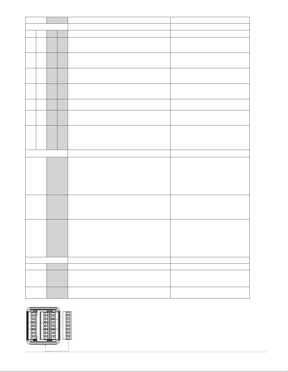
Slot A Slot B
Output Terminal Function Configuration
1234
X1
W1
Y1
F1
G1
H1
L1
K1
J1
W2
Y2
L2
K2
L2
K2
X3
W3
Y3
W4Y4dc-
F3
G3
H3
L3
K3
J3
L4K4normally open
common (Any switched dc output can use this common.)
dc- (open collector)
dc+
dc+
voltage or current voltage +
current +
normally open
common
normally closed
normally open
common
common
L1K1L2K2L3K3L4K4normally open
common
Communications
CB
CA
CC
CB
CA
C5
C3
C2
V+
CH
SH
CL
E8
E7
E6
E5
E4
E3
E2
E1
Modbus RTU EIA-485 T+/R+
Modbus RTU EIA-485 T-/RModbus RTU EIA-485 common
Modbus RTU EIA-485 T+/R+
Modbus RTU EIA-485 T-/RModbus RTU EIA-232 common
Modbus RTU EIA-232 to DB9 pin 2
Modbus RTU EIA-232 to DB9 pin 3
DeviceNet™ power
Positive side of DeviceNet™ bus
Shield interconnect
Negative side of DeviceNet™ bus
V-
DeviceNet™ power return
EtherNet/IP™ and Modbus TCP unused
EtherNet/IP™ and Modbus TCP unused
EtherNet/IP™ and Modbus TCP receive EtherNet/IP™ and Modbus TCP unused
EtherNet/IP™ and Modbus TCP unused
EtherNet/IP™ and Modbus TCP receive +
EtherNet/IP™ and Modbus TCP transmit EtherNet/IP™ and Modbus TCP transmit +
Inputs
12
T1
S1
R1
Terminal Definitions for Slots A and B.
Slot A
Output 1 Output 2 Input 1
Slot B Slot C
Output 3 Output 4 Input 2
T2
S2
R2
T2
S2
Power485 CommsDig I/O 5 & 6
S2 (RTD) or current +, potentiometer wiper
S3 (RTD), thermocouple -, current - or volts S1 (RTD), thermocouple + or volts +
mA ac
mA ac
Slot B
Communications
Switched dc/open collector
output 1: PM6 _ _ C _-_ _ _ _ A _ _
output 3: PM6 _ _ _ _-_ _ C _ A _ _
Switched dc
output 2: PM6 _ _ _ C-_ _ _ _ A _ _
output 4: PM6 _ _ _ _-_ _ _ C A _ _
Universal Process
output 1: PM6 _ _ F _-_ _ _ _ A _ _
output 3: PM6 _ _ _ _-_ _ F _ A _ _
Mechanical Relay 5 A, Form C
output 1: PM6 _ _ E _-_ _ _ _ A _ _
output 3: PM6 _ _ _ _-_ _ E _ A _ _
No-arc 15 A, Form A
output 2: PM6 _ _ _ H-_ _ _ _ A _ _
Mechanical Relay 5 A, Form A
output 2: PM6 _ _ _ J-_ _ _ _ A _ _
output 4: PM6 _ _ _ _-_ _ _ J A _ _
Solid-state Relay 0.5 A, Form A
output 1: PM6 _ _ K _-_ _ _ _ A _ _
output 2: PM6 _ _ _ K-_ _ _ _ A _ _
output 3: PM6 _ _ _ _-_ _ K
_ A _ _
output 4: PM6 _ _ _ _-_ _ _ K A _ _
Modbus RTU 232/485 Communications
PM6 _ _ _ _-2 A A A A _ _
DeviceNet™ Communications
PM6 _ _ _ _-5 A A A A _ _
Ethernet 10/100 supporting EtherNet/IP™
and Modbus TCP
PM6 _ _ _ _-3 A A A A _ _
Universal Sensor
input 1: all configurations
input 2: PM6 _ _ _ _-_ (R or L) _ _ A _ _
Current Transformer
PM6 _ _ _ _-_ T _ _ A _ _
or
Watlow EZ-ZONE® PM Integrated Controller • 11 • Chapter 2 Install and Wire
Slot C Terminal Function Configuration
9899power input: ac or dc+
power input: ac or dc-
CC
Standard Bus or Modbus RTU EIA-485 common
CA
Standard Bus or Modbus RTU EIA-485 T-/R-
CB
Standard Bus or Modbus RTU EIA-485 T+/R+
CF
Standard Bus EIA-485 common
CD
Standard Bus EIA-485 T-/R-
CE
Standard Bus EIA-485 T+/R+
B5
digital input-output common
D6
digital input or output 6
D5
digital input or output 5
all
Standard Bus or Modbus
PM6 _ _ _ _-1 _ _ _ A _ _
PM6 _ _ _ _-(A, 2 or 3) _ _ _ A _ _
PM6 _ 2 _ _-_ _ _ _ A _ _
PM6 _ 4 _ _-_ _ _ _ A _ _
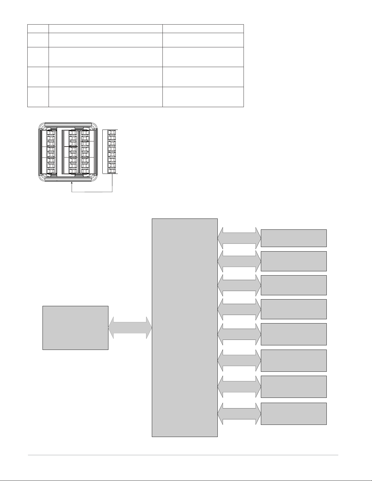
Terminal Definitions for Slot C.
Slot A
Output 1 Output 2 Input 1
Slot B Slot C
Output 3 Output 4 Input 2
Power485 CommsDig I/O 5 & 6
or
Slot B
Communications
Controller
Power Supply
12 to 40VÎ (dc)
24 to 28VÅ (ac)
85 to 264VÅ (ac)
Safety Isolation
Low voltage power bus
and
internal bus
No Isolation
No Isolation
No Isolation
Low-voltage
Isolation
Safety Isolation
Low-voltage
Isolation
Low-voltage
Isolation
Low-voltage
Isolation
Digital Inputs and
Outputs 5 & 6
Switched DC, Open
Collector, Process Outputs
Analog Input 1
Analog Input 2
Mechanical Relay,
Solid-state Relay &
No-arc Relay Outputs
EIA-485
Communications Port
RS-232/EIA-485
Communications Port
Ethernet
Communications Port
PM Integrated isolation blocks.
Low-voltage Isolation: 42V peak
Safety Isolation: 1,528VÅ (ac)
Watlow EZ-ZONE® PM Integrated Controller • 12 • Chapter 2 Install and Wire
Ó
Warning:
Use National Electric (NEC)
or other country-specific
standard wiring and safety
practices when wiring and
connecting this controller to
a power source and to electrical sensors or peripheral
devices. Failure to do so may
result in damage to equipment and property, and/or
injury or loss of life.
Note:
Maximum wire size termination and torque rating:
• 0.0507 to 3.30 mm2 (30 to
12 AWG) single-wire termination or two 1.31 mm2 (16
AWG)
• 0.8 Nm (7.0 lb.-in.) torque
Note:
Adjacent terminals may be
labeled differently, depending on the model number.
Low Power
Slot C
98
99
CF
CD
CE
B5
D6
D5
power
power
High Power
Slot C
98
99
CF
CD
CE
B5
D6
D5
power
power
fuse
• 12 to 40VÎ (dc)
• 20 to 28VÅ (ac)
• 20 to 28VÅ (ac) Semi Sig F47
• 47 to 63 Hz
• 10VA maximum power consumption
PM6 _ (3 or 4) _ _-_ _ _ _ A _ _
fuse
• 85 to 264VÅ (ac)
• 100 to 240VÅ (ac) Semi Sig F47
• 47 to 63 Hz
• 10VA maximum power consumption
PM6 _ (1 or 2) _ _-_ _ _ _ A _ _
Note:
To prevent damage to the
controller, do not connect
wires to unused terminals.
Note:
Maintain electrical isolation
between analog input 1, digital input-outputs, switched
dc/open collector outputs and
process outputs to prevent
ground loops.
Note:
The control output common
terminal and the digital common terminal are referenced
to different voltages and
must remain isolated.
Digital Input or Output 5
Slot C
98
99
CF
CD
CE
common -
B5
D6
input or output +
D5
Digital Input
• update rate 10 Hz
• dry contact or dc voltage
DC voltage
• maximum input 36V at 3 mA
• minimum high state 3V @ 0.25 mA
• maximum low state 2V
Dry contact
• minimum open resistance 500 Ω
• maximum closed resistance 100 Ω
• maximum short circuit 13 mA
Digital Input or Output 6
Slot C
98
99
CF
CD
CE
common -
B5
input or output +
D6
D5
Digital Input
• update rate 10 Hz
• dry contact or dc voltage
DC voltage
• maximum input 36V at 3 mA
• minimum high state 3V @ 0.25 mA
• maximum low state 2V
Dry contact
• minimum open resistance 500 Ω
• maximum closed resistance 100 Ω
• maximum short circuit 13 mA
Digital Output
• update rate 10 Hz
• output voltage 24V
• current limit, Output 5, 24 mA
maximum
• capable of driving a 3-pole
DIN-A-MITE
• open-circuit voltage 22 to
32VÎ (dc)
PM6 _ (2 or 4) _ _-_ _ _ _ A _ _
Digital Output
• update rate 10 Hz
• output voltage 24V
• current limit, Output 6, 10 mA
maximum
• capable of driving a single-pole
DIN-A-MITE
• open-circuit voltage 22 to
32VÎ (dc)
PM6 _ (2 or 4) _ _-_ _ _ _ A _ _
Watlow EZ-ZONE® PM Integrated Controller • 13 • Chapter 2 Install and Wire
Ó
Warning:
Use National Electric (NEC)
or other country-specific
standard wiring and safety
practices when wiring and
connecting this controller to
a power source and to electrical sensors or peripheral
devices. Failure to do so may
result in damage to equipment and property, and/or
injury or loss of life.
Note:
Maximum wire size termination and torque rating:
• 0.0507 to 3.30 mm2 (30 to
12 AWG) single-wire termination or two 1.31 mm2 (16
AWG)
• 0.8 Nm (7.0 lb.-in.) torque
Note:
Adjacent terminals may be
labeled differently, depending on the model number.
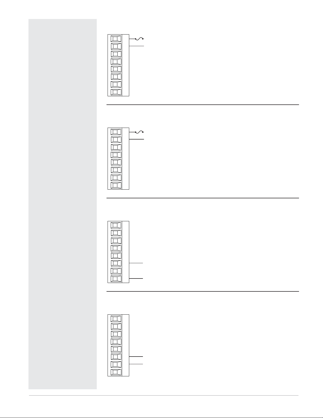
Input 1 Thermocouple
Slot A
L1
K1
J1
L2
K2
T1
-
S1
+
R1
Input 1 RTD
Slot A
L1
K1
J1
L2
K2
T1
S3
S1
S1
R1
2-wire
S2
S3
S1
• 20 Ω maximum source resistance
• >20 MΩ input impedance
• 3 microampere open-sensor detection
• Thermocouples are polarity sensitive. The negative lead (usually
red) must be connected to S1.
• To reduce errors, the extension wire for thermocouples must be
of the same alloy as the thermocouple.
PM6 _ _ _ _-_ _ _ _ A _ _ (all)
Slot A
L1
K1
J1
L2
K2
T1
S1
R1
3-wire
• platinum, 100 and 1,000 Ω @ 0°C
• calibration to DIN curve (0.00385 Ω/Ω/°C)
• 20 Ω total lead resistance
• RTD excitation current of 0.09 mA typical. Each
ohm of lead resistance may affect the reading by
0.03°C.
• For 3-wire RTDs, the S1 lead (usually white) must
be connected to R1.
• For best accuracy use a 3-wire RTD to compensate
for lead-length resistance. All three lead wires must
have the same resistance.
PM6 _ _ _ _-_ _ _ _ A _ _ (all)
Note:
To prevent damage to the
controller, do not connect
wires to unused terminals.
Note:
Maintain electrical isolation
between analog input 1, digital input-outputs, switched
dc/open collector outputs and
process outputs to prevent
ground loops.
Note:
The control output common
terminal and the digital common terminal are referenced
to different voltages and
must remain isolated.
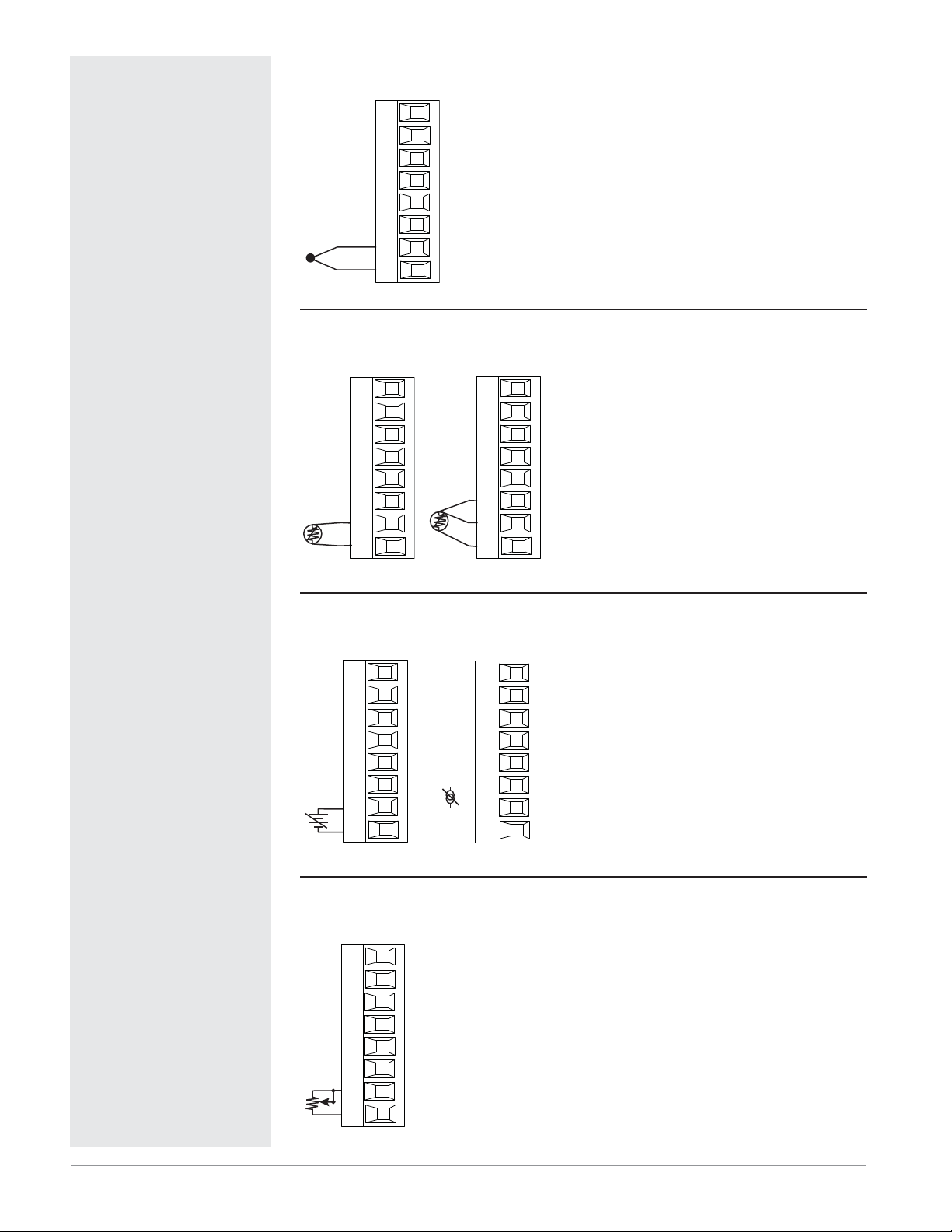
Input 1 Process
Slot A
L1
K1
J1
L2
K2
T1
-
S1
+
R1
volts
Input 1 Potentiometer
Slot A
L1
K1
J1
• Use a 1 kΩ potentiometer.
PM6 _ _ _ _-_ _ _ _ A _ _ (all)
CW
CCW
L2
K2
T1
S1
R1
+
-
Slot A
L1
K1
J1
L2
K2
T1
S1
R1
amperes
• 0 to 20 mA @ 100 Ω input impedance
• 0 to 10VÎ (dc) @ 20 kΩ input impedance
• 0 to 50 mVÎ (dc) @ 20 kΩ input impedance
• scalable
PM6 _ _ _ _-_ _ _ _ A _ _ (all)
Watlow EZ-ZONE® PM Integrated Controller • 14 • Chapter 2 Install and Wire
Ó
Warning:
Use National Electric (NEC)
or other country-specific
standard wiring and safety
practices when wiring and
connecting this controller to
a power source and to electrical sensors or peripheral
devices. Failure to do so may
result in damage to equipment and property, and/or
injury or loss of life.
Note:
Maximum wire size termination and torque rating:
• 0.0507 to 3.30 mm2 (30 to
12 AWG) single-wire termination or two 1.31 mm2 (16
AWG)
• 0.8 Nm (7.0 lb.-in.) torque
Note:
Adjacent terminals may be
labeled differently, depending on the model number.
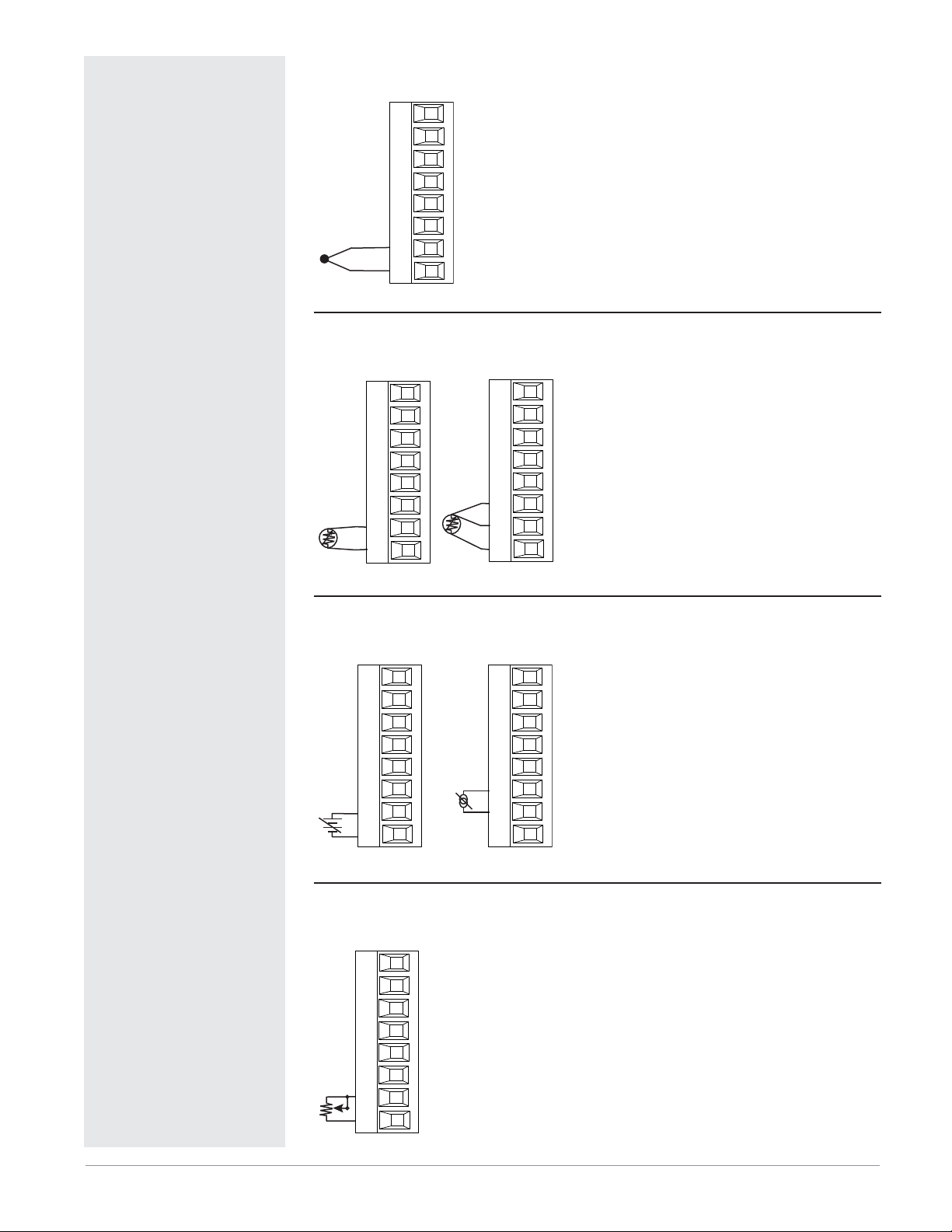
Input 2 Thermocouple
Slot B
L3
K3
J3
L4
K4
T2
-
S2
+
R2
Input 2 RTD
Slot B
L3
K3
J3
L4
K4
T2
S3
S2
S1
R2
2-wire
S2
S3
S1
• 20 Ω maximum source resistance
• >20 MΩ input impedance
• 3 microampere open-sensor detection
• Thermocouples are polarity sensitive. The negative lead (usually
red) must be connected to S2.
• To reduce errors, the extension wire for thermocouples must be
of the same alloy as the thermocouple.
PM6 _ _ _ _-_ (R or L) _ _ A _ _
Slot B
L3
K3
J3
L4
K4
T2
S2
R2
3-wire
• platinum, 100 and 1,000 Ω @ 0°C
• calibration to DIN curve (0.00385 Ω/Ω/°C)
• 20 Ω total lead resistance
• RTD excitation current of 0.09 mA typical. Each
ohm of lead resistance may affect the reading by
0.03°C.
• For 3-wire RTDs, the S1 lead (usually white) must
be connected to R2.
• For best accuracy use a 3-wire RTD to compensate
for lead-length resistance. All three lead wires must
have the same resistance.
PM6 _ _ _ _-_ (R or L) _ _ A _ _
Note:
To prevent damage to the
controller, do not connect
wires to unused terminals.
Note:
Maintain electrical isolation
between analog input 1, digital input-outputs, switched
dc/open collector outputs and
process outputs to prevent
ground loops.
Note:
The control output common
terminal and the digital common terminal are referenced
to different voltages and
must remain isolated.
Input 2 Process
Slot B
L3
K3
J3
L4
K4
T2
-
S2
+
R2
volts
Input 2 Potentiometer
Slot B
L3
K3
J3
• Use a 1 kΩ potentiometer.
PM6 _ _ _ _-_ (R or L) _ _ A _ _
CW
CCW
L4
K4
T2
S2
R2
+
-
Slot B
L3
K3
J3
L4
K4
T2
S2
R2
amperes
• 0 to 20 mA @ 100 Ω input impedance
• 0 to 10VÎ (dc) @ 20 kΩ input impedance
• 0 to 50 mVÎ (dc) @ 20 kΩ input impedance
• scalable
PM6 _ _ _ _-_ (R, T or L) _ _ A _ _
Watlow EZ-ZONE® PM Integrated Controller • 15 • Chapter 2 Install and Wire

Ó
Warning:
Use National Electric (NEC)
or other country-specific
standard wiring and safety
practices when wiring and
connecting this controller to
a power source and to electrical sensors or peripheral
devices. Failure to do so may
result in damage to equipment and property, and/or
injury or loss of life.
Note:
Maximum wire size termination and torque rating:
• 0.0507 to 3.30 mm2 (30 to
12 AWG) single-wire termination or two 1.31 mm2 (16
AWG)
• 0.8 Nm (7.0 lb.-in.) torque
Input 2 Current Transformer
Slot B
L3
K3
J3
L4
K4
T2
S2
R2
• Input range is 0 to 50 mA.
• current transformer part number: 16-0246
• 100 Ω input impedance
• response time: 1 second maximum
• accuracy +/-1 mA typical
PM6 _ _ _ _-_ T _ _ A _ _
Note:
Adjacent terminals may be
labeled differently, depending on the model number.
Note:
To prevent damage to the
controller, do not connect
wires to unused terminals.
Note:
Maintain electrical isolation
between analog input 1, digital input-outputs, switched
dc/open collector outputs and
process outputs to prevent
ground loops.
Note:
The control output common
terminal and the digital common terminal are referenced
to different voltages and
must remain isolated.
Watlow EZ-ZONE® PM Integrated Controller • 16 • Chapter 2 Install and Wire
Ó
Warning:
Use National Electric (NEC)
or other country-specific
standard wiring and safety
practices when wiring and
connecting this controller to
a power source and to electrical sensors or peripheral
devices. Failure to do so may
result in damage to equipment and property, and/or
injury or loss of life.
Note:
Maximum wire size termination and torque rating:
• 0.0507 to 3.30 mm2 (30 to
12 AWG) single-wire termination or two 1.31 mm2 (16
AWG)
• 0.8 Nm (7.0 lb.-in.) torque
Note:
Adjacent terminals may be
labeled differently, depending on the model number.
Note:
To prevent damage to the
controller, do not connect
wires to unused terminals.
Note:
Maintain electrical isolation
between analog input 1, digital input-outputs, switched
dc/open collector outputs and
process outputs to prevent
ground loops.
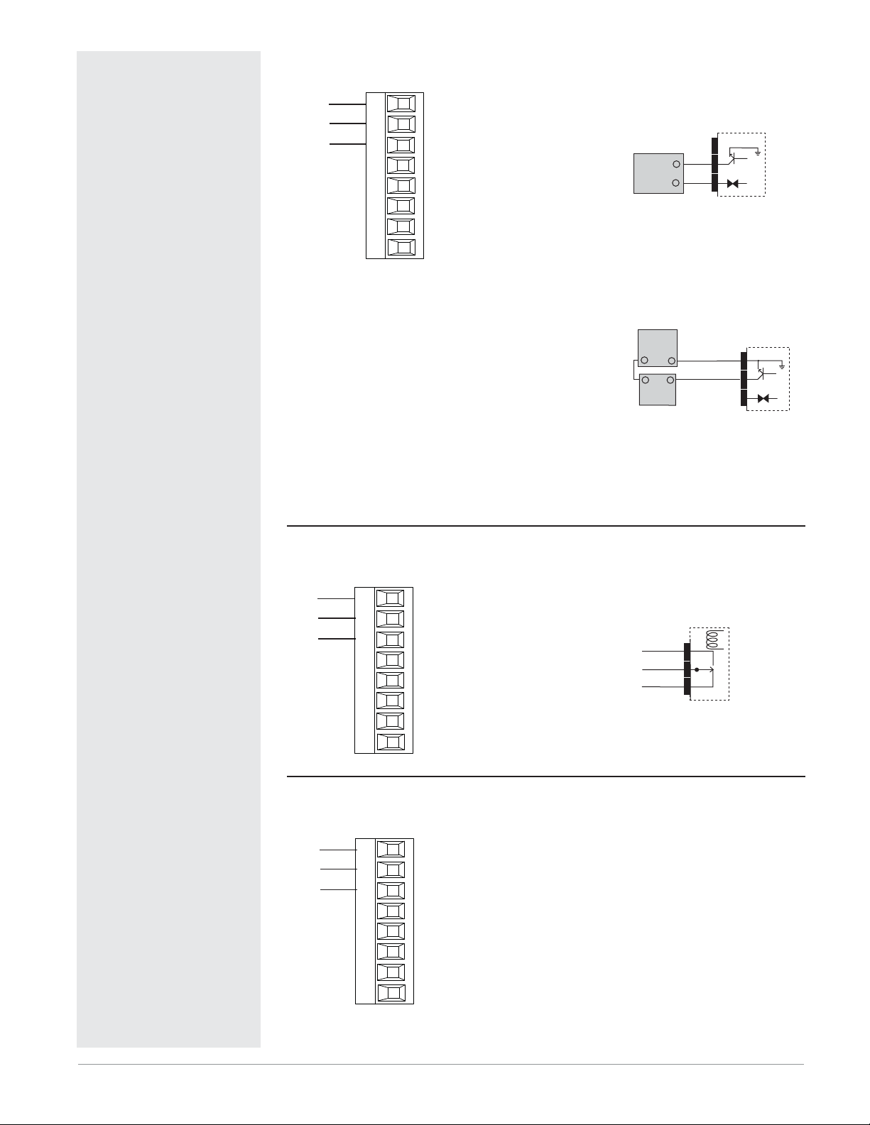
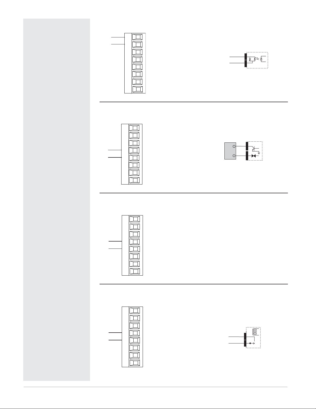
Output 1 Switched DC/Open Collector
Switched DC
Slot A
common
dc - (open collector)
dc +
X1
W1
Y1
L2
K2
T1
S1
R1
• 30 mA dc maximum supply
current
• short circuit limited to <50 mA
• 22 to 32VÎ (dc) open circuit
voltage
• Use dc- and dc+ to drive external solid-state relay.
• DIN-A-MITE compatible
• single-pole: up to 4 in parallel
or 4 in series
• 2-pole: up to 2 in parallel or 2
in series
• 3-pole: up to 2 in series
Open Collector
• 100 mA maximum output current sink
• 30VÎ (dc) maximum supply
voltage
• Any switched dc output can
use the common terminal.
• Use an external power supply
to control a dc load, with the
load positive to the positive
of the power supply, the load
negative to the open collector
and common to the power supply negative.
See Quencharc note.
PM6 _ _ C _-_ _ _ _ A _ _
Output 1 Mechanical Relay, Form C
normally open
common
normally closed
L1
K1
J1
L2
K2
T1
S1
R1
Slot A
• 5 A at 240VÅ (ac) or 30VÎ (dc)
maximum resistive load
• 20 mA at 24V minimum load
• 125 VA pilot duty at 120/240VÅ
(ac), 25 VA at 24VÅ (ac)
• 100,000 cycles at rated load
• Output does not supply power.
• for use with ac or dc
See Quencharc note.
PM6 _ _ E _-_ _ _ _ A _ _
Load
Powe r
Supply
+
normally
L1
common
K1
J1
normally
+
Load
open
closed
-
+
-
-
Switched DC
dc-
W1
dc+
Y1
X1
common
W1
Mechanical
Relay
Internal
Circuitry
Internal
Circuitry
dc-
dc+
Open
Collector
Internal
Circuitry
Note:
The control output common
terminal and the digital common terminal are referenced
to different voltages and
must remain isolated.
Quencharc Note:
Switching pilot duty inductive
loads (relay coils, solenoids,
etc.) with the mechanical
relay, solid state relay or
open collector output options
Output 1 Universal Process
volts or current -
volts +
current +
F1
G1
H1
L2
K2
T1
S1
R1
Slot A
• 0 to 20 mA into 800 Ω maximum load
• 0 to 10VÎ (dc) into voltage 1
kΩ minimum load
• scalable
• output supplies power
• cannot use voltage and current
outputs at same time
• Output may be used as retransmit or control.
PM6 _ _ F _-_ _ _ _ A _ _
requires use of an R.C. suppressor.
Note: If output 1 is a universal process output, output 2 cannot function as a variable-time-base output.
Watlow EZ-ZONE® PM Integrated Controller • 17 • Chapter 2 Install and Wire
Ó
Warning:
Use National Electric (NEC)
or other country-specific
standard wiring and safety
practices when wiring and
connecting this controller to
a power source and to electrical sensors or peripheral
devices. Failure to do so may
result in damage to equipment and property, and/or
injury or loss of life.
Note:
Maximum wire size termination and torque rating:
• 0.0507 to 3.30 mm2 (30 to
12 AWG) single-wire termination or two 1.31 mm2 (16
AWG)
• 0.8 Nm (7.0 lb.-in.) torque
Note:
Adjacent terminals may be
labeled differently, depending on the model number.
Output 1 Solid-state Relay, Form A
normally open
common
L1
K1
L2
K2
T1
S1
R1
Slot A
• 0.5 A at 20 to 264VÅ (ac) maxi-
mum resistive load
• 20 VA 120/240VÅ (ac) pilot duty
• opto-isolated, without contact
suppression
• maximum off state leakage of
105 microamperes
• output does not supply power
• Do not use on dc loads.
• See Quencharc note.
PM6 _ _ K _-_ _ _ _ A _ _
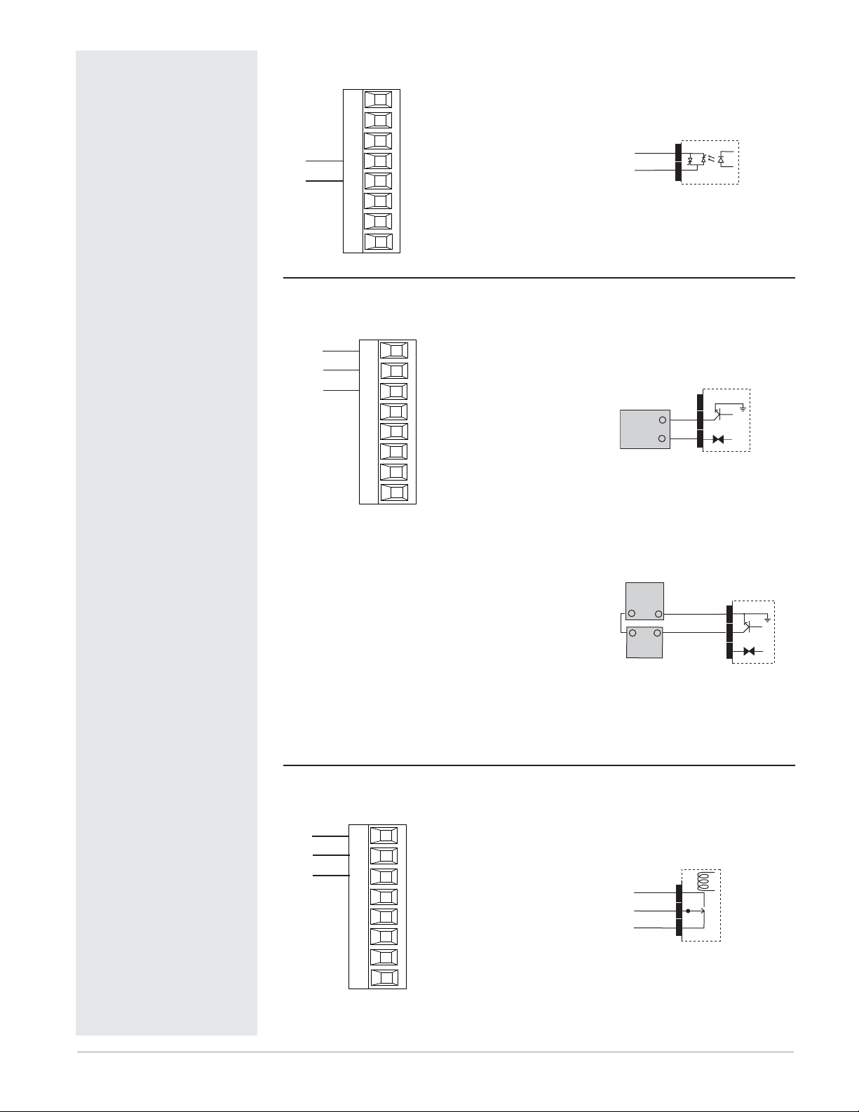
Output 2 Switched DC
dc+
dc-
Slot A
L1
K1
J1
W2
Y2
T1
S1
R1
• 10 mA DC maximum supply
current
• short circuit limited to <50 mA
• 22 to 32VÎ (dc) open circuit
voltage
• use dc- and dc+ to drive external solid-state relay
• DIN-A-MITE compatible
• single-pole: up to 2 in series,
none in parallel
PM6 _ _ _ C-_ _ _ _ A _ _
L1
K1
Load
common
+
normally
open
dc-
W2
dc+
Solid-state Relay
Internal Circuitry
Switched DC
Y2
Internal
Circuitry
Note:
To prevent damage to the
controller, do not connect
wires to unused terminals.
Note:
Maintain electrical isolation
between analog input 1, digital input-outputs, switched
dc/open collector outputs and
process outputs to prevent
ground loops.
Note:
The control output common
terminal and the digital common terminal are referenced
to different voltages and
must remain isolated.
Quencharc Note:
Switching pilot duty inductive
loads (relay coils, solenoids,
etc.) with the mechanical
relay, solid state relay or
open collector output options
requires use of an R.C. suppressor.
Output 2 No-arc Relay, Form A
Slot A
normally open
common
L1
K1
J1
L2
K2
T1
S1
• 15 A at 85 to 264VÅ (ac) resis-
tive load only
• 2,000,000 cycle rating for no-arc
circuit (preliminary)
• 100 mA minimum load
• 2 mA maximum off state leakage
• Do not use on dc loads.
• Output does not supply power.
PM6 _ _ _ H-_ _ _ _ A _ _
R1
Output 2 Mechanical Relay, Form A
Slot A
normally open
common
L1
K1
J1
L2
K2
T1
S1
R1
• 5 A at 240VÅ (ac) or 30VÎ (dc)
maximum resistive load
• 20 mV at 24V minimum load
• 125 VA pilot duty @ 120/240VÅ
(ac), 25 VA at 24VÅ (ac)
• 100,000 cycles at rated load
• Output does not supply power.
• for use with ac or dc
See Quencharc note.
PM6 _ _ _ J-_ _ _ _ A _ _
L2
K2
normally
open
common
Mechanical
Relay
Internal
Circuitry
Watlow EZ-ZONE® PM Integrated Controller • 18 • Chapter 2 Install and Wire
Ó
Warning:
Use National Electric (NEC)
or other country-specific
standard wiring and safety
practices when wiring and
connecting this controller to
a power source and to electrical sensors or peripheral
devices. Failure to do so may
result in damage to equipment and property, and/or
injury or loss of life.
Note:
Maximum wire size termination and torque rating:
• 0.0507 to 3.30 mm2 (30 to
12 AWG) single-wire termination or two 1.31 mm2 (16
AWG)
• 0.8 Nm (7.0 lb.-in.) torque
Note:
Adjacent terminals may be
labeled differently, depending on the model number.
Note:
To prevent damage to the
controller, do not connect
wires to unused terminals.
Note:
Maintain electrical isolation
between analog input 1, digital input-outputs, switched
dc/open collector outputs and
process outputs to prevent
ground loops.
Output 2 Solid-state Relay, Form A
normally open
common
Slot A
L1
K1
J1
L2
K2
T1
S1
R1
• 0.5 A at 20 to 264VÅ (ac) maxi-
mum resistive load
• 20 VA 120/240VÅ (ac) pilot duty
• opto-isolated, without contact
suppression
• maximum off state leakage of
105 microamperes
• Output does not supply power.
• Do not use on dc loads.
See Quencharc note.
PM6 _ _ _ K-_ _ _ _ A _ _
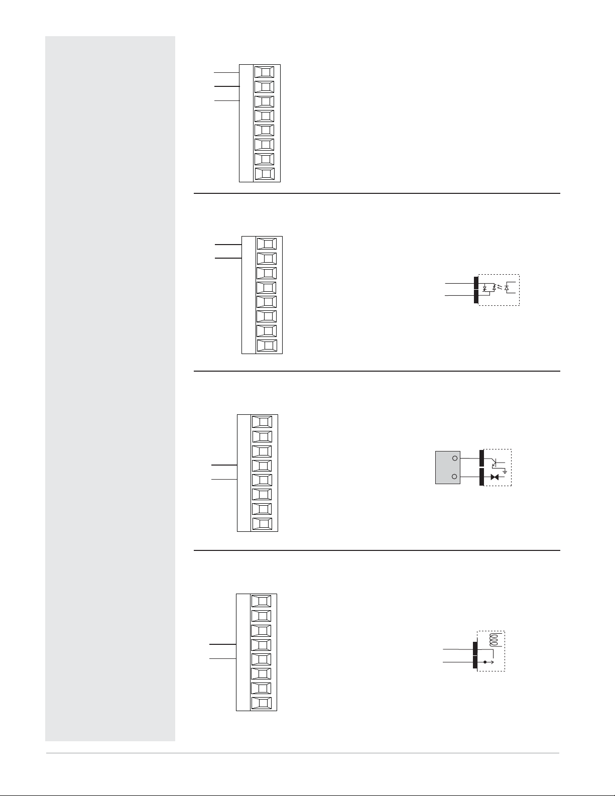
Output 3 Switched DC/Open Collector
Switched DC
Slot B
common
dc - (open collector)
dc +
X3
W3
Y3
L4
K4
T2
S2
R2
• 30 mA dc maximum supply
current
• short circuit limited to <50 mA
• 22 to 32VÎ (dc) open circuit
voltage
• Use dc- and dc+ to drive external solid-state relay.
• DIN-A-MITE compatible
• single-pole: up to 4 in parallel
or 4 in series
• 2-pole: up to 2 in parallel or 2
in series
• 3-pole: up to 2 in series
Open Collector
• 100 mA maximum output current sink
• 30VÎ (dc) maximum supply
voltage
• Any switched dc output can
use the common terminal.
• Use an external power supply
to control a dc load, with the
load positive to the positive
of the power supply, the load
negative to the open collector
and common to the power supply negative.
See Quencharc note.
PM6 _ _ _ _-_ _ C _ A _ _
L2
K2
+
Load
Powe r
Supply
+
Load
common
normally
open
-
+
-
-
Solid-state Relay
Internal Circuitry
Switched DC
dc-
W3
dc+
Y3
Internal
Circuitry
X3
common
dc-
W3
dc+
Open
Collector
Internal
Circuitry
Note:
The control output common
terminal and the digital common terminal are referenced
to different voltages and
must remain isolated.
Quencharc Note:
Switching pilot duty inductive
loads (relay coils, solenoids,
etc.) with the mechanical
relay, solid state relay or
open collector output options
Output 3 Mechanical Relay, Form C
normally open
common
normally closed
L3
K3
J3
L4
K4
T2
S2
R2
Slot B
• 5 A at 240VÅ (ac) or 30VÎ (dc)
maximum resistive load
• 20 mA at 24V minimum load
• 125 VA pilot duty at 120/240VÅ
(ac), 25 VA at 24VÅ (ac)
• 100,000 cycles at rated load
• Output does not supply power.
• for use with ac or dc
See Quencharc note.
PM6 _ _ _ _-_ _ E _ A _ _
L3
K3
J3
normally
open
common
normally
closed
Mechanical
Relay
Internal
Circuitry
requires use of an R.C. suppressor.
Watlow EZ-ZONE® PM Integrated Controller • 19 • Chapter 2 Install and Wire
Ó
Warning:
Use National Electric (NEC)
or other country-specific
standard wiring and safety
practices when wiring and
connecting this controller to
a power source and to electrical sensors or peripheral
devices. Failure to do so may
result in damage to equipment and property, and/or
injury or loss of life.
Output 3 Universal Process
volts or current -
volts +
current +
F3
G3
H3
L4
K4
T2
S2
R2
Slot B
• 0 to 20 mA into 800 Ω maximum load
• 0 to 10VÎ (dc) into voltage 1
kΩ minimum load
• scalable
• Output supplies power.
• cannot use voltage and current
outputs at same time
• Output may be used as retransmit or control.
PM6 _ _ _ _-_ _ F _ A _ _
Output 3 Solid-state Relay, Form A
Note: If output 3 is a universal process
output, output 4 cannot function as a
variable-time-base output.
Note:
Maximum wire size termination and torque rating:
• 0.0507 to 3.30 mm2 (30 to
12 AWG) single-wire termination or two 1.31 mm2 (16
AWG)
• 0.8 Nm (7.0 lb.-in.) torque
Note:
Adjacent terminals may be
labeled differently, depending on the model number.
Note:
To prevent damage to the
controller, do not connect
wires to unused terminals.
Note:
Maintain electrical isolation
between analog input 1, digital input-outputs, switched
dc/open collector outputs and
process outputs to prevent
ground loops.
normally open
common
Slot B
L3
K3
• 0.5 A at 20 to 264VÅ (ac) maxi-
• 20 VA 120/240VÅ (ac) pilot
• opto-isolated, without contact
L4
K4
T2
S2
R2
• maximum off state leakage of
• Output does not supply power.
• Do not use on dc loads.
See Quencharc note.
PM6 _ _ _ _ -_ _ K _ A _ _
Output 4 Switched DC
Slot B
• 10 mA DC maximum supply
• short circuit limited to <50 mA
• 22 to 32VÎ (dc) open circuit
• Use dc- and dc+ to drive exter-
• DIN-A-MITE compatible
• single-pole: up to 2 in series,
PM6 _ _ _ _-_ _ _ C A _ _
dc-
dc+
L3
K3
J3
W4
Y4
T2
S2
R2
mum resistive load
duty
suppression
105 microamperes
current
voltage
nal solid-state relay.
none in parallel
L3
K3
Load
normally
open
common
+
-
Solid-state Relay
Internal Circuitry
Switched DC
dc-
W4
dc+
Y4
Internal
Circuitry
Note:
The control output common
terminal and the digital common terminal are referenced
to different voltages and
must remain isolated.
Quencharc Note:
Switching pilot duty inductive
loads (relay coils, solenoids,
etc.) with the mechanical
relay, solid state relay or
open collector output options
Output 4 Mechanical Relay, Form A
Slot B
normally open
common
L3
K3
J3
L4
K4
T2
S2
R2
• 5 A at 240VÅ (ac) or 30VÎ (dc)
maximum resistive load
• 20 mV at 24V minimum load
• 125 VA pilot duty at 120/240VÅ
(ac), 25 VA at 24VÅ (ac)
• 100,000 cycles at rated load
• Output does not supply power.
• for use with ac or dc
See Quencharc note.
PM6 _ _ _ _-_ _ _ J A _ _
L4
K4
normally
open
common
Mechanical
Relay
Internal
Circuitry
requires use of an R.C. suppressor.
Watlow EZ-ZONE® PM Integrated Controller • 20 • Chapter 2 Install and Wire

Ó
Warning:
Use National Electric (NEC)
or other country-specific
standard wiring and safety
practices when wiring and
connecting this controller to
a power source and to electrical sensors or peripheral
devices. Failure to do so may
result in damage to equipment and property, and/or
injury or loss of life.
Note:
Maximum wire size termination and torque rating:
• 0.0507 to 3.30 mm2 (30 to
12 AWG) single-wire termination or two 1.31 mm2 (16
AWG)
• 0.8 Nm (7.0 lb.-in.) torque
Output 4 Solid-state Relay, Form A
normally open
common
Slot B
L3
K3
J3
L4
K4
T2
S2
R2
• 0.5 A at 20 to 264VÅ (ac) maxi-
mum resistive load
• 20 VA 120/240VÅ (ac) pilot duty
• opto-isolated, without contact
suppression
• maximum off state leakage of
105 microamperes
• Output does not supply power.
• Do not use on dc loads.
See Quencharc note.
PM6 _ _ _ _-_ _ _ K A _ _
L4
K4
normally
open
common
Solid-state Relay
Internal Circuitry
Note:
Adjacent terminals may be
labeled differently, depending on the model number.
Note:
To prevent damage to the
controller, do not connect
wires to unused terminals.
Note:
Maintain electrical isolation
between analog input 1, digital input-outputs, switched
dc/open collector outputs and
process outputs to prevent
ground loops.
Note:
The control output common
terminal and the digital common terminal are referenced
to different voltages and
must remain isolated.
Quencharc Note:
Switching pilot duty inductive
loads (relay coils, solenoids,
etc.) with the mechanical
relay, solid state relay or
open collector output options
requires use of an R.C. suppressor.
Watlow EZ-ZONE® PM Integrated Controller • 21 • Chapter 2 Install and Wire

Ó
Warning:
Use National Electric (NEC)
or other country-specific
standard wiring and safety
practices when wiring and
connecting this controller to
a power source and to electrical sensors or peripheral
devices. Failure to do so may
result in damage to equipment and property, and/or
injury or loss of life.
Note:
Maximum wire size termination and torque rating:
• 0.0507 to 3.30 mm2 (30 to
12 AWG) single-wire termination or two 1.31 mm2 (16
AWG)
• 0.8 Nm (7.0 lb.-in.) torque
Note:
Adjacent terminals may be
labeled differently, depending on the model number.
Standard Bus EIA-485 Communications
Slot C
98
99
CF
CD
CE
B5
D6
D5
common
T-/R-
T+/R+
• Wire T-/R- to the A terminal of
the EIA-485 port.
• Wire T+/R+ to the B terminal of
the EIA-485 port.
• Wire common to the common
terminal of the EIA-485 port.
• Do not route network wires
with power wires. Connect network wires in daisy-chain fashion when connecting multiple
devices in a network.
• Do not connect more than 16
EZ-ZONE
network.
• maximum network length:
1,200 meters (4,000 feet)
• 1/8th unit load on EIA-485 bus
PM6 _ _ _ _-(A, 2 or 3) _ _ _ A _ _
Modbus RTU or Standard Bus EIA-485 Communications
Slot C
98
99
CC
CA
CB
B5
D6
D5
common
T-/R-
T+/R+
• Wire T-/R- to the A terminal of
the EIA-485 port.
• Wire T+/R+ to the B terminal of
the EIA-485 port.
• Wire common to the common
terminal of the EIA-485 port.
• Do not route network wires
with power wires. Connect network wires in daisy-chain fashion when connecting multiple
devices in a network.
• A termination resistor may be
required. Place a 120 Ω resistor
across T+/R+ and T-/R- of last
controller on network.
• Only one protocol per port is
available at a time: either Modbus RTU or Standard Bus.
• Do not connect more than 16
EZ-ZONE
Standard Bus network.
• Maximum number of EZZONE
network is 247.
• maximum network length:
1,200 meters (4,000 feet)
• 1/8th unit load on EIA-485 bus.
PM6 _ _ _ _-1 _ _ _ A _ _
®
PM controllers on a
®
controllers on a
®
controllers on a Modbus
Note:
To prevent damage to the
controller, do not connect
wires to unused terminals.
Note:
Maintain electrical isolation
between analog input 1, digital input-outputs, switched
dc/open collector outputs and
process outputs to prevent
ground loops.
Note:
The control output common
terminal and the digital common terminal are referenced
to different voltages and
must remain isolated.
Note:
Avoid continuous writes
within loops. Excessive
writes to EEPROM will cause
premature EEPROM failure.
The EEPROM is rated for
1,000,000 writes.
EIA-232/485 Modbus RTU Communications
Slot B
485 T+/R+
485 common
485 T+/R+
232 common
232 (TX) to DB9 pin 2 (RD)
232 (RD) to DB9 pin 3 (TX)
Modbus-IDA
Terminal
DO A CA or CD T-/R-
D1 B CB or CE T+/R+
common common CC or CF common
485 T-/R-
485 T-/R-
EIA/TIA-485
CB
CA
CC
CB
CA
C5
C3
C2
Name
• Wire T-/R- to the A terminal
of the EIA-485 port.
• Wire T+/R+ to the B terminal of the EIA-485 port.
• Wire common to the common terminal of the EIA485 port.
• Do not route network wires
with power wires. Connect
network wires in daisychain fashion when connecting multiple devices in a
network.
• A termination resistor may
be required. Place a 120 Ω
resistor across T+/R+ and
T-/R- of last controller on
network.
• Do not wire to both the EIA485 and the EIA-232 pins at
the same time.
• Two EIA-485 terminals of
T/R are provided to assist in
daisy-chain wiring.
Watlow Termi-
nal Label
Function
• Do not connect more than
one EZ-ZONE
ler on an EIA-232 network.
• Do not connect more than
16 EZ-ZONE
on a Standard Bus EIA-485
network.
• Maximum number of EZZONE
Modbus network is 247.
• maximum EIA-232 network
length: 15 meters (50 feet)
• maximum EIA-485 network
length: 1,200 meters (4,000
feet)
• 1/8th unit load on EIA-485
bus.
PM6 _ _ _ _-2 AAA A _ _
®
PM control-
®
controllers
®
controllers on a
Watlow EZ-ZONE® PM Integrated Controller • 22 • Chapter 2 Install and Wire
 Loading...