

Page 1
Tubular and
Process Assemblies
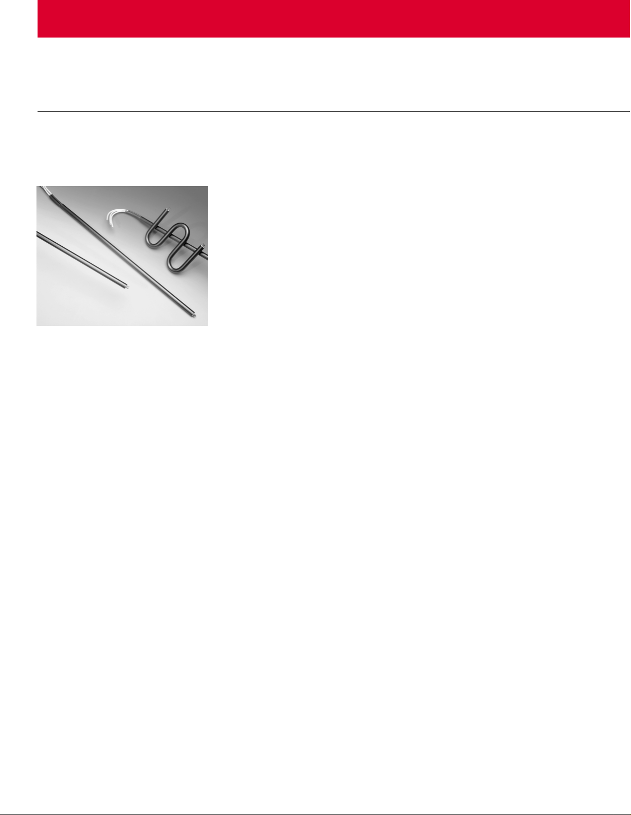
WATROD Heating
Elements
Multicoil Single- or DoubleEnded Elements
Watlow’s new tubular element with
multiple coils and/or thermocouples
inside one sheath answers the
need for a versatile, innovative
tubular heater. Our new, patentpending method of packaging a
thermocouple inside of a heater
with one or more resistance coils,
gives the ability to sense a heaters’
internal temperature accurately,
every time.
Moreover, this is the first tubular
heater in the industry with threephase capability. The three coil,
three-phase heater will offer a lower
amperage solution while delivering
the full power required in a
compact heater package.
Previously three separate heaters
would have been required to do the
same job; therefore Watlow’s new
multicoil heater capabilities save
money.
Watlow has the capability to put up
to two coils in a 0.375 or 0.430
diameter heater and up to three
coils in a 0.475 or 0.490 diameter
heater. Any one or more of these
coils can be a resistance wire or a
thermocouple. The bending
formations are virtually limitless;
while mounting options are similar to
other Watlow tubular heaters. The
three-phase multicoil heaters can be
single ended with three leads for
three-phase wye hook up. Watlow
recommends using an epoxy
moisture seal or silicone-based seal.
Watlow’s multicoil heaters are
available in all standard materials
such as Incoloy
stainless steel, and can be formed
into almost any configuration. Our
five thermocouple and/or coil
options for multicoil tubular
configurations will meet most
requirements; however, we are
always interested in discussing the
use of different materials or
changing the number of coils and
thermocouples.
®
, 304 and 316
Features and Benefits
• Three-phase capability results
in one element versus three,
lower amperage, reduced installation time and lower overall cost.
• Internal thermocouple allows
responsive and accurate, internal, high-limit sensing and
reduced assembly costs.
• Single ended allows for mount-
ing in a
fitting with three-phase capability.
• Multiple coil options reduce
inventory by allowing dual
voltage capability.
• Versatile forming capabilities
can be formed into virtually any
configuration.
• Internal construction allows
space savings because drilling
and tapping of flange is
unnecessary; plus, the interior
thermocouple eliminates
contamination buildup around the
external sensing tip, reducing the
possibility of false readings.
Applications
• Foodservice
• Process
• Medical
• Milled groove
• Plastics
• Plating
• Oven heating
• Semiconductor
1
inch NPT or
⁄2
3
inch NPT
⁄4
276
Page 2
W A T L O W
Tubular and
Process Assemblies
WATROD Heating
Elements
Multicoil Single- or DoubleEnded Elements
Continued
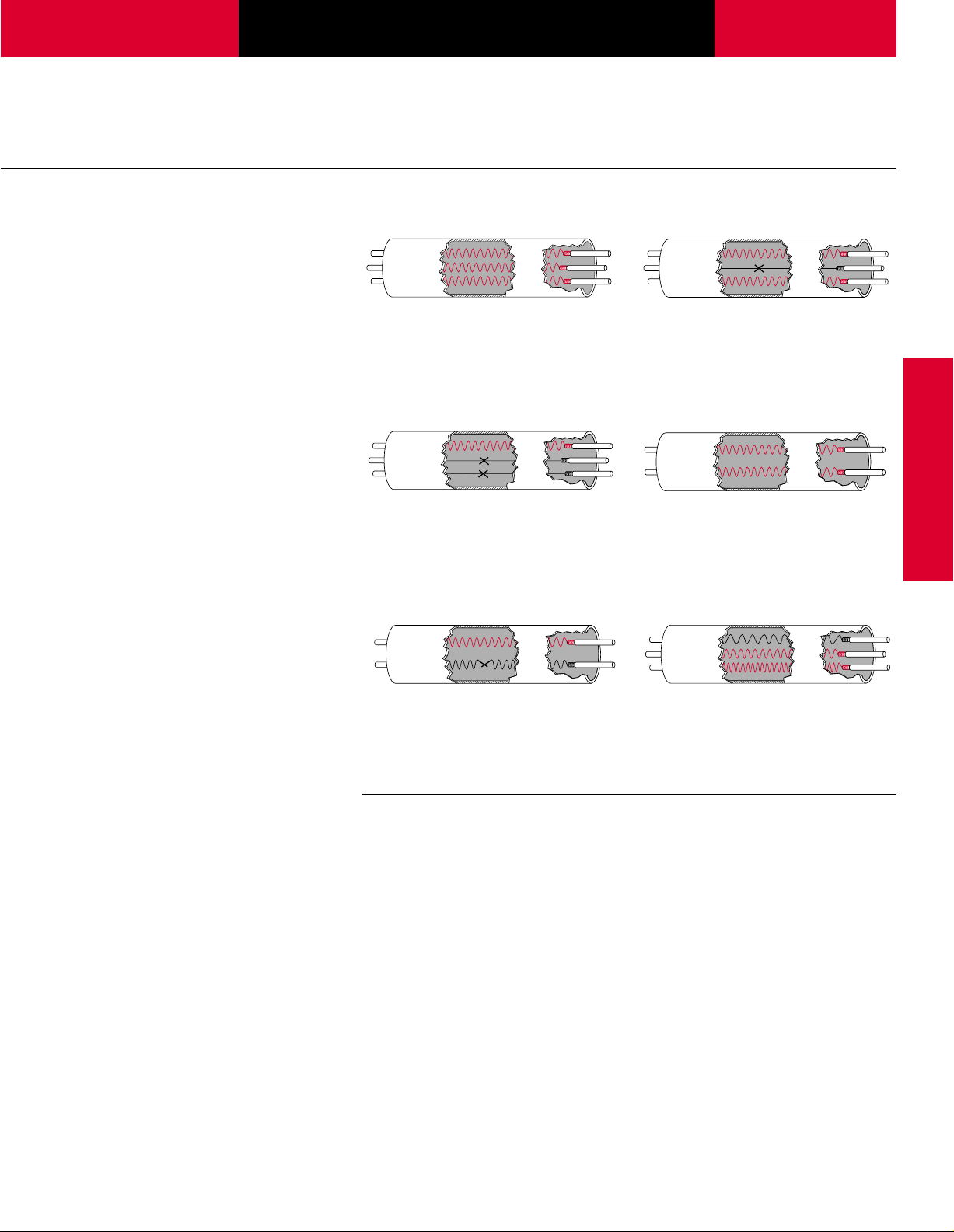
Options
Option A
3-phase tubular, 0.475 and 0.490
inch diameter.
Option C
1-phase tubular with one resistance
wire and two thermocouples, 0.475
and 0.490 inch diameter.
Option E
Option B
1-phase tubular with two resistance
wires and one thermocouple, 0.475
and 0.490 inch diameter.
Option D
1-phase tubular with three different
one phase circuits, 0.475 and 0.490
inch diameter
Option F
.
WATROD
Sil-A-Blend™is a trademark of Radix Wire
Company.
1-phase tubular with two resistance
coils, 0.375, 0.430, 0.475 and 0.490
inch diameter.
Specifications
Termination style is currently
limited to lead wires 392°F (200˚C)
Sil-A-Blend
Moisture seals are required,
options include:
• Standard epoxy with temperature
rating to 266˚F (130°C). Typical
applications include water/oil
immersion.
• Lavacone with temperature rating
to 300˚F (148.9°C). Typical
application includes air heating.
• High-temp ceramic rated to
2800˚F (1537.8°C).
• Consult factory for other moisture
seal options.
• ULTRAGARD with temperature
rating to 700˚F (375˚C).
™
or 482°F (250˚C) GGS.
1-phase tubular with one resistance
coil and one thermocouple, 0.375,
0.430, 0.475 and 0.490 inch
diameter.
Mounting options include:
• Mounting brackets
• Locator washers
• Mounting collars
• Water-tight bulkheads
Maximum trim length is 237 inches
(6020 mm). Heater designs with trim
length greater than 120 inches
(3048 mm) must be reviewed with
factory.
®
Sheath materials: Incoloy
and 316 stainless steel, consult
factory for other sheath material
options.
Internal thermocouple options:
Type K is used, consult factor y for
Type J ther mocouple options.
U.S. Patent Pending
, 304
277
Page 3
Tubular and
Process Assemblies
WATROD Heating
Elements
Specifications
Double-Ended Single-Ended
Applications Direct immersion Vacuums Platens
Hot runner mold (manifold) Semiconductor Forced air
Forced air Deicing antennas
Ovens Plastic wrap cutting
Radiant Seal bars
Clamp-on
Watt Density Stock: up to 60 (9.3) Stock: up to 20 (3.1)
2
W/in
(W/cm2) Made-to-Order (M-t-O): up to 120 (18.6) M-t-O: up to 45 (6.9)
Element Diameters Dia.
inch (mm) 0.210 0.660 (5.3) (4.26) 0.375 1.178 (9.5) (7.600)
and Surface Area per Linear 0.260 0.817 (6.6) (5.27) 0.430 1.351 (10.9) (8.717)
inch (cm) 0.315 0.990 (8.0) (6.38) 0.475 1.492 (12.0) (9.626)
Diameter Tolerance 0.332 1.043 (8.4) (6.73) 0.490 1.539 (12.4) (9.930)
± 0.005 inch (0.13 mm) 0.375 1.178 (9.5) (7.60) 0.625 1.963 (15.9) (12.665)
0.430 1.351 (10.9) (8.72)
0.475 1.492 (12.0) (9.63)
0.490 1.539 (12.4) (9.93)
0.625 1.963 (15.9) (12.66)
Sheath Materials Stock: Incoloy
Maximum Operating 316 stainless steel 1200°F (650°C)
Temperature Steel 750°F (400°C)
M-t-O: Inconel
Sheath Length By Diameter
inch (mm) Dia.
Stock: Stock:
0.260 20 to 80 (6.6) (510 to 2030) 0.375 15 to 40 (9.5) (380 to 1015)
0.315 12 to 100 (8.0) (305 to 2540)
0.375 11 to 180 (9.5) (275 to 4555)
0.430 15 to 120 (10.9) (380 to 3050)
0.475 20 to 157 (12.0) (510 to 3990)
M-t-O: M-t-O:
0.210 9 to 130 (5.3) (230 to 3300) 0.375 11 to 125 (9.5) (280 to 3175)
0.260 9 to 275 (6.6) (230 to 6980) 0.430 11 to 106 (10.9) (280 to 2690)
0.315 9 to 270 (8.0) (230 to 6850) 0.475 11 to 125 (12.0) (280 to 3175)
0.332 9 to 125 (8.5) (230 to 3170) 0.490 11 to 125 (12.4) (280 to 3175)
0.375 11 to 325 (9.5) (280 to 8255) 0.625 11 to 125 (15.9) (280 to 3175)
0.430 11 to 268 (10.9) (280 to 6810)
0.475 11 to 275 (12.0) (280 to 6985)
0.490 11 to 275 (12.4) (280 to 6985)
0.625 11 to 275 (15.9) (280 to 6985)
2
in
®
Copper 350°F (175°C)
®
600 1800°F (980°C) M-t-O: Incoloy
®
Incoloy
316 stainless steel 1200°F (650°C) 304 stainless steel 1200°F (650°C)
304 stainless steel 1200°F (650°C) Steel 750°F (400°C)
Steel 750°F (400°C)
Copper 350°F (175°C)
®
Monel
Titanium Consult Factory
Sheath Sheath Sheath Sheath
Length Dia. Length Dia. Length Dia. Length
Dia. (mm) cm
1600°F (870°C) Stock: Incoloy
1600°F (870°C) 316 stainless steel 1200°F (650°C)
Consult Factory
2
Dia. in
2
®
®
Dia. (mm) cm
1200°F (650°C)
1600°F (870°C)
2
278
Page 4
W A T L O W
Tubular and
Process Assemblies
WATROD Heating
Elements
Specifications
Double-Ended Single-Ended
Minimum No-Heat Length Sheath No-Heat Sheath No-Heat Sheath No-Heat Sheath No-Heat
inch (mm) Length Length Length Length Length
11 to 20 1 (280 to 510) (25) 11 to 20 11⁄2 (280 to 5100) (38)
21 to 50 1
51 to 80 1
81 to 110 1
111 to 140 1
141 to 170 2 (3580 to 4320) (51)
171 to 200 2
201 & up 2
Maximum V oltage/Amperage
By Dia. 0.260 (6.6) 250VÅ(ac) 15 0.375 (9.5) 480VÅ(ac) 30
inch (mm) 0.315 (8.0) 480VÅ(ac) 30 0.430 (10.9) 480VÅ(ac) 30
Ohms Per Heated Inch Dia.
By Dia. 0.210 0.100Ω 16Ω
inch 0.260 0.080Ω 25Ω 0.375 0.200Ω 34Ω
Terminations Stock: Threaded stud Stock: Flexible lead wires
Seals Stock: Silicone resin 390°F (200°C) Stock: Silicone resin 390°F (200°C)
Mounting Options Threaded bulkheads Threaded bulkhead
Surface Finish Options Belt polishing Bright Anneal Belt polishing Bright Anneal
Agency Recognition UL
Dia. Volts Amps Dia. Volts Amps
0.332 (8.5) 480VÅ(ac) 30 0.475 (12.0) 480VÅ(ac) 30
0.375 (9.5) 480VÅ(ac) 30 0.490 (12.4) 480VÅ(ac) 30
0.430 (10.9) 600VÅ(ac) 40 0.625 (15.9) 480VÅ(ac) 30
0.475 (12.0) 600VÅ(ac) 40
0.490 (12.4) 600VÅ(ac) 40
0.625 (15.9) 600VÅ(ac) 40
0.315 0.050Ω 25Ω 0.430 0.200Ω 34Ω
0.332 0.050Ω 23Ω 0.475 0.200Ω 34Ω
0.375 0.020Ω 18Ω 0.490 0.200Ω 34Ω
0.430 0.025Ω 30Ω 0.625 0.200Ω 34Ω
0.475 0.030Ω 30Ω
0.490 0.030Ω 30Ω
0.625 0.030Ω 25Ω
M-t-O: Threaded stud M-t-O: Flexible lead wires
M-t-O: Ceramic base 2800°F (1535°C) M-t-O: Silicone rubber
Mounting brackets Locator washers
Locator washers Mounting collars
Mounting collars
Passivation Passivation
®
Component to 480VÅ(ac) (file # E52951/E56488) UL®Component to 240VÅ(ac) (file # E52951)
CSA Component to 600VÅ(ac) (file # 31388) CSA Component to 240VÅ(ac) (file # 31388)
1
⁄4
1
⁄2 (1295 to 2030) (38) 51 to 80 21⁄8 (1295 to 2030) (54)
5
⁄8
3
⁄4 (2820 to 3555) (44) 111 to 125 25⁄8 (2820 to 3175) (67)
1
⁄4 (4345 to 5080) (57)
1
2 (5105 & up) (64)
⁄
Minimum Maximum Dia. Minimum Maximum
Screw lug (plate) Rubber overmolds
Quick connect (spade)
Flexible lead wires
Rubber overmolds
ULTRAGARD 700°F (375°C) ULTRAGARD 700°F (375°C)
Ceramic-to-metal 500°F (260°C) Silicone resin 392°F (200°C)
Silicone rubber
Silicone resin 392°F (200°C)
Epoxy resin 266/350°F (130/177°C)
(535 to 1270) (32) 21 to 50 1
(2055 to 2795) (42) 81 to 110 2
1
2 inch (13 mm) No-heat length on all blunt ends
⁄
(RTV)
500°F (260°C) Epoxy resin 266/350°F (130/177°C)
Length Length Length
3
⁄4
3
⁄8
(533 to 1270) (44)
(2055 to 2795) (60)
(RTV)
500˚F (260°C)
➀
WATROD
➀ Not applicable to 0.375 inch diameter single-ended WATROD
279
Page 5

Tubular and
1
/
8
"(3 mm)
Approx.
Sheath Diameter
A
B
C
Process Assemblies
WATROD Heating
Elements
Options
Moisture Resistant Seals
WATROD’s MgO insulating material
is hygroscopic. To prevent moisture
contamination from entering the
heater, an appropriate moisture seal
must be used. Choosing the correct
seal is important to the life and
the maximum continuous use
temperature is not exceeded at the
seal location. Most end seals are
applied with a small cavity in the
end of the heater. The seal will also
help prevent arcing at the terminal
ends.
performance of the heater. Be sure
End Seal Options
Code Seal UL
End Seal Number Color Depth Recognition Temperature Typical or General Usage/Application
Standard Epoxy EC Cream
Intermediate Epoxy EB Blue
High-Temp. Epoxy HTE Amber
Silicone Resin SR Clear
Silicone Fluid SF Clear N/A No 392°F (200°C) Moisture resistance of the MgO, or High-Temp.
Lavacone LC Dark Brown3⁄16" Yes 392°F (200°C) Porous seal for the FIREBAR
Silicone Rubber RTV RTV Red-Orange
ULTRAGARD UG Clear
High-Temp. Ceramic HTC White
3
⁄16" Yes 266°F (130°C) General purpose for moisture resistance
3
⁄16" Yes 350°F (177°C) Intermediate temp. rating for moisture resistance
3
⁄16" No 450°F (232°C) Higher temp. rating for moisture resistance
1
⁄16" Yes 392°F (200°C) General usage on tubular products
3
⁄16" Yes 500°F (260°C) General usage on FIREBAR applications
3
⁄16" Yes 700°F (350°C) High temp. around seal area and for
3
⁄16" No 2800°F (1538°C) Very high temperature applications
®
Max. Cont. Use
ceramic seal (storage only)
vacuum applications
Ceramic-to-Metal End Seal
External Finishes
Belt Polishing
Belt polishing sands the oxidized
sheath to a bright finish. This finish
is available only on alloy sheath
materials.
To order, specify belt polishing.
280
Sheath
Diameter A B C Thread
inch (mm) inch (mm) inch (mm) inch (mm) Size
0.260 (6.6) 1
0.315 (8) 1
0.430 (10.9) 21⁄8 (54)1⁄2 (13)21⁄32 (10) #1⁄4-28
To order specify, ceramic-to-metal end seal.
Ceramic-to-metal end seals with
threaded stud terminations provide
an air-tight seal for continuous
terminal temperatures up to 500°F
Bright Annealing
A process that produces a smooth,
metallic finish. It is a special
annealed finish created in a nonoxidizing atmosphere. This finish is
popular in the pharmaceutical and
food and beverage markets.
To order, specify bright annealing.
11
⁄16
7
⁄8 (43)1⁄2 (13)13⁄32 (10) #10-32
(40)
1
⁄2
(13)
13
⁄32
(10) #8-32
(260°C). Watlow does not
recommend this seal if terminations
are exposed to temperatures
exceeding 500°F (260°C).
Passivation
During the manufacturing process,
particles of iron or tool steel may
become embedded in the stainless
steel or alloy sheath. If not removed,
these particles may corrode,
produce rust spots and/or
contaminate the process. For critical
sheath applications, passivation will
remove free iron from the sheath.
To order, specify passivation.
Page 6

W A T L O W
1
"
(25 mm)
19
/32
"
(15 mm)
5
/16
"
(8 mm)
3
/4
"
(19 mm)
5
/16
"
(8 mm)
18
/32
"
(15 mm)
1
/2
"
(13mm)
1
/2
"
(13 mm)
1
/2
"
(13 mm)
1
/2
"
(13 mm)
1
/2
"
(13 mm)
1
/2
"
(13 mm)
1
/4
"
(6 mm)
3
/4
"
(19 mm)
1
1
/2
"
(38 mm)
19
/32
"
(15 mm)
1
/4
"
(6 mm)
1
/2
"
(13 mm)
A
B
Sheath Diameter
3
/4
" min.
straight req'd
Tubular and
Process Assemblies
WATROD Heating
Elements
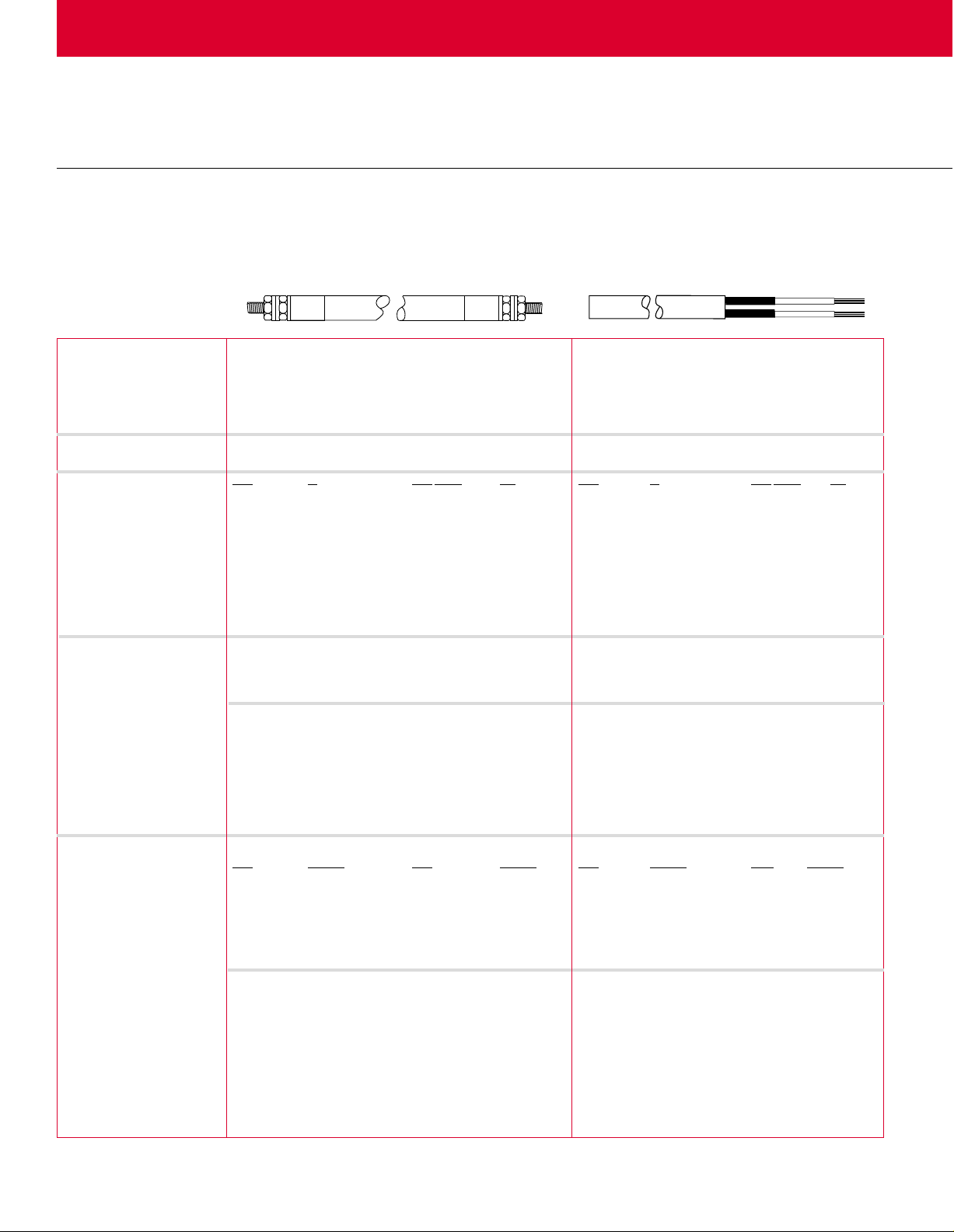
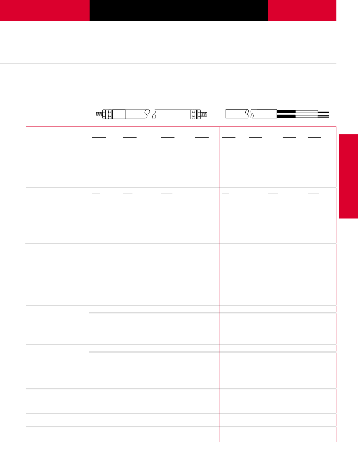
W A TROD T erminations
Double-ended WATROD elements
are available with a variety of
terminations. Single-ended
WATROD elements are available
with only flexible lead wires.
The following table and illustrations
detail the terminations available with
double- or single-ended
WATRODs—for each available
sheath diameter.
Standard flexible lead wires are
12 inches (305 mm), Sil-A-Blend™
390°F (200°C) unless otherwise
specified. Insulation options include
TGGT (480°F/250°C) plus other
temperature ratings. Consult factory
for availability.
Overmolds are available for flexible
lead wires only. Available in silicone
rubber (390°F/200°C), neoprene
(212°F/90°C) and other materials.
Consult factory for details.
Sheath Threaded Screw Lug Quick Connect Flexible Lead Wire
WATROD Diameter Stud
aa
(Plate) (Spade) Lead Wires Overmolds
Element inch (mm) ABCDEFG H J
Double- 0.260 (6.6) #6-32 Yes Yes Yes Yes Yes Yes Yes Yes
Ended 0.315 (8.0) #10-32 Yes Yes Yes Yes Yes Yes Yes Yes
0.335 (8.5) #10-32 Yes Yes Yes Yes Yes Yes Yes No
0.375 (9.5) #10-32 Yes Yes Yes Yes Yes Yes Yes No
0.430 (10.9) #10-32 Yes Yes Yes Yes Yes Yes Yes Yes
0.475 (12.0) #10-32 Yes Yes Yes Yes Yes Yes Yes Yes
0.490 (12.4) #10-32 Yes Yes Yes Yes Yes Yes Yes No
0.625 (15.9) #10-32 Yes Yes Yes Yes Yes Yes Yes No
Single- 0.375 (9.5) No No No No No No No Yes No
Ended 0.430 (10.9) No No No No No No No Yes Yes
0.475 (12.0) No No No No No No No Yes Yes
0.490 (12.4) No No No No No No No Yes No
0.625 (15.9) No No No No No No No Yes Yes
Threaded Stud Screw Lug (Plate) Quick Connect (Spade) Flexible Lead Wires
BA
E
H
WATROD
a Optional #8-32, 1⁄4 inch and 4 or
5 mm studs available. Consult
factory for details.
C
D
F
G
J
Rubber Overmolds
Overmold Availability
Sheath
Diameter A B
inch (mm) inch (mm) inch (mm)
0.260 (6.6) 21⁄2 (63.5)1⁄2 (13.0)
0.315 (8.0) 2
1
⁄2 (63.5)1⁄2 (13.0)
0.375 (9.5) 21⁄2 (63.5)5⁄8 (15.9)
1
0.430 (10.9) 2
0.475 (12.0) 2
⁄2 (63.5)5⁄8 (15.9)
1
⁄2 (63.5)5⁄8 (15.9)
0.625 (15.9) 21⁄2 (63.5)7⁄8 (22.2)
281
Page 7

Tubular and
F
R
A
H
Dia.
R
1
A
H
Dia.
R
1
<°
(Angle)
F
R
2
A
K
Dia.
R
1
R
2
H
Process Assemblies
WATROD Heating
Elements
Double-Ended W A TR OD Bend
Formations
Double-ended WATROD heating
elements can be formed into
Minimum radius for various sheath
diameters and lengths are shown in
the Bend Formations chart below.
Illustrated on pages 282 to 286 are
the 36 common bend configurations
available on both stock and madeto-order WATROD heating elements.
spirals, compounds, multi-axis and
multi-planes from 36 common bend
configurations. Custom bending
with tighter tolerances can be made
to meet specific application needs.
Formation is limited by the minimum
bend radius (R) and the straight
length (F) required beyond the
bend. In order to locate the end of a
heated length within a bend, the
radius must be three inches (76 mm)
or larger. Additionally, overall length
tolerance (T) must be included in
one or more of the straight lengths.
WATROD Length Tolerance (T)
Sheath Length Length Tolerance
inch (mm) inch (mm)
11-50 (280-1270) ±1⁄8 (±3)
51-110 (1295-2795) ±3⁄16 (±5)
111-170 (2820-4320) ±
171-200 (4345-5080) ±3⁄8 (±10)
201 & up (5105 & up) ±1⁄2 (±13)
Single-Ended WATROD Bend
Formations
Watlow does not recommend field
bending single-ended WATROD
elements. Formation is limited by
the minimum radius of a bend (R)
1
⁄4 (±6)
Bend Formations
and the straight length (F) beyond
the bend. The radius must be
three inches (75 mm) or more for
the heated length’s end to be inside
a bend.
Additionally, the overall length
tolerance (T) must be provided for
in one or more of the specified
lengths.
The four common bend configurations available for standard and
made-to-order single-ended
WATROD elements are Figures 1, 6,
22 and 28.
To order a common bend formation,
specify the bend figure number,
dimensions and critical tolerances.
WATROD Minimum Radius
Sheath Diameter Field Bend R
inch (mm) inch (mm) inch (mm) inch (mm)
0.260 (6.6)
0.315 (8.0)
0.335 (8.5) 1 (25)
0.375 (9.5) 1 (25)
0.430 (10.9) 1 (25)
0.475 (12.0) 1 (25)
0.490 (12.5) 1 (25)
0.625 (15.9) 11⁄2 (38)
a R is the inside radius of a bend.
b F is the distance from the sheath’s end to the start of the first
bend.
3
⁄4 (19)
3
⁄4 (19)
aa
Factory RaaFbbDimension
3
⁄8 (10)
1
⁄2 (13)
1
⁄2 (13) 1 (25)
1
⁄2 (13)
1
⁄2 (13)
5
(16) 1 (25)
⁄8
5
⁄8 (16) 1 (25)
3
⁄4 (19) 1 1⁄2 (38)
1
⁄2 (13)
1
⁄2 (13)
1
⁄2 (13)
3
⁄4 (19)
Figure 1 Figure 2 Figure 3
282
SL = 2A + 1.14R1- 0.43 Dia.
(For pricing, use 1 bend)
SL = 2A + 2F + 1.14R1+ 0.0175 (<°)
(2R2+ Dia.) - 0.43 Dia.
(For pricing, use 3 bends)
SL = 2K - 0.86R2- 2.86 Dia. + 2A + 1.14R
(For pricing, use 3 bends)
1
Page 8

W A T L O W
Dia.
R
1
R
2
H
B
R
3
R
3
B
K
A
C
View B
View A
<°
(Angle)
Dia.
R
1
R
2
H
H
A
C
L
Dia.
R
1
R
2
H
Dia.
R
2
R
1
L
A
H
Dia.
R
1
C
A
L
X Hairpins
A
H
Dia.
R
1
R
2
R
1
L
A
K
Dia.
R
1
R
2
R
1
R
3
H
L
Dia.
B
L
K
R
1
R
1
R
4
R
2
R
3
A
H
Dia.
R
1
H
R
2
R
1
View B
R
3
K
L
R
3
View A
B
K
A
Tubular and
Process Assemblies
WATROD Heating
Elements
Figure 4 Figure 6Figure 5
WATROD
View A: SL = 2K- 1.72R3- 7.72 Dia. + 2C
- 0.86R2+ 2A + 1.14R
1
View B: SL = 2K- 2.28R3- 3.72 Dia. + 2C
- 0.86R2+ 2A + 1.14R
1
SL = 0.0175(<˚) (2R2+ Dia.)
+1.14R1+ 0.43 Dia.
(For pricing, use 3 bends)
SL = L + 1.14R2- 0.86 Dia. + C + 1.14R1+ A
(For pricing, use 2 bends)
(For pricing, use 5 bends)
Figure 7 Figure 8 Figure 9
SL = 2A + 2.28R
(For pricing, use 3 bends)
- 1.29 Dia. + 2L + 1.14R
2
1
X = number of outside hairpins
SL = 2A + 3.42R
- 1.29 Dia. + 2L
1
(For pricing, use 5 bends)
SL = 2A + 2.28R1- 1.29 Dia. + 2L + 1.14R
(For pricing, use 3 bends)
Figure 10 Figure 11 Figure 12
2
SL = 2K - 0.86R3- 3.72 Dia. + 2A + 2L
(For pricing, use 5 bends)
+ 2.28R1+ 1.14R
SL = 2K - 086R
2
- 0.86R4- 6.15 Dia. + 2B + 2A
3
+ 2L + 2.28R1+ 1.14R
(For pricing, use 7 bends)
View A: SL = 2K + 2B + 2A + 2L + 2.28R
2
+ 1.14R2- 1.72R3- 6.15 Dia.
View B: SL = 2K + 2A + 2L + 2.28R1+ 1.14R
1
2
- 2.28R3- 2.15 Dia.
(For pricing, use 5 bends)
283
Page 9

Tubular and
R
3
R
3
R
2
H
C
A
L
K
B
R
1
R
1
Dia.
Dia.
A
L
K
B
R
1
R
1
R
3
R
2
H
R
4
A
Dia.
B
X Hairpins
K
H
R
4
L
R
1
R
1
R
1
R
2
R
2
R
3
X Hairpins
R
1
R
1
R
1
R
2
R
2
H
A
Dia.
L
R
1
R
2
X Hairpins
Dia.
R
1
R
1
R
2
A
L
H
K
R
3
A
R
4
R
3
X Hairpins
Dia.
R
1
R
1
R
1
R
2
R
2
C
L
H
B
K
Process Assemblies
WATROD Heating
Elements
Figure 13
SL = 2B + 2A + 2L - 6.717 Dia. - 1.717R
- H - 0.858R2- 0.858R
(For pricing, use 5 bends)
3
1
SL+2K+2A+2L+2.28R1+1.14R2+2B
-6.15 Dia. -0.86R3+0.86R
4
(For pricing use 7 bends)
Figure 15Figure 14
X = number of outside hairpins
SL = 2K + 2A + 2K(X - 1) + 2B - 0.86R
+ 1.14R1(X) + 1.14R2(X - 1) - 4.86 Dia. - (2X - 1)
(For pricing, use 9 bends if X = 3 hairpins)
Figure 16 Figure 17 Figure 18
0.43 Dia.
- 0.86R
3
4
X = number of outside hairpins
SL = 2A + 0.43 Dia. (1 - 2X) + 2L (X - 1) + 1.14R
+ 1.14R2(X - 1)
(For pricing, use 5 bends if X = 3 hairpins)
284
X = number of outside hairpins
SL = 1.14R
1
+ 1.14R1X -0.86R3+ 2L X - 2L + 2A + 2K
X - 0.88 Dia. X - 1.14R2 - 2 Dia.
2
(For pricing, use 7 bends if X = 3 hairpins)
X = number of outside hairpins
SL = 2L + 2K + 2B + 2C (X - 1) - 0.86R
- 0.86R4- 4.86 Dia. + 1.14R1(X)
+ 1.14R2(X - 1) - (2X - 1) 0.43 Dia.
(For pricing, use 9 bends if X = 3 hairpins)
3
Page 10

W A T L O W
A
C
R
1
R
3
X
Hairpins
R
1
R
5
R
2
R
2
L
H
K
R
4
B
R
1
R
4
K
B
R
5
VIEW A
OPTIONAL VIEW B
C
R
1
(6 places)
Dia.
C
M
B
H
E
L
A
K
Ref.
Ref.
R
2
R
3
L
K
R
1
R
1
Dia.
R
2
H
A
A
H
R
1
Dia.
A
H
R
1
R
2
Dia.
K
A
H
R
1
R
1
R
2
Dia.
L
R
3
K
L
R
1
(4 places)
R
2
(2 places)
Dia.
K
B
A
H
L
A
Dia.
R
2
(2 places)
B
H
K
R
1
(4 places)
C
R1 (4 places)
Dia.
R
3
L
B
K
A
R
2
(2 places)
H
Tubular and
Process Assemblies
WATROD Heating
Elements
Figure 19 Figure 20 Figure 21
WATROD
X = number of outside hairpins
View A and B: SL = 2K + 2A + 2B + 2C + 2L (X - 1)
+ 1.14R1(X) + 1.14R2(X - 1) - 0.86R3- 0.86R
4
SL = 2K + 2C + B + 2A + 2L - 2.58R1- 0.86R2-
0.86R3- 12.15 Dia.
(For pricing, use 10 bends)
SL = 2A + 2K - H - 2.28R
- 3.29 Dia.
(For pricing, use 4 bends)
- 0.86R
1
2
- 0.86R5- 7.29 Dia. - (2X - 1) 0.43 Dia.
(For pricing, use 11 bends if X = 3 hairpins)
Figure 24Figure 23Figure 22
SL = 2A - 0.86R1- 1.43 Dia. + H
(For pricing, use 2 bends)
SL = 2K - 0.86R2- 3.86 Dia. + 2A - 0.86R1+ H
(For pricing, use 4 bends)
SL = 2K + 2L + H - 0.86R
- 7.29 Dia.
(For pricing, use 6 bends)
- 0.86R2- 0.86R
1
3
Figure 27Figure 26Figure 25
SL = 2K + 2A + 2L - H - 1.72R
(For pricing, use 6 bends)
- 6.92 Dia.
- 0.86R
1
2
SL = 2K + 2A + 2L - H - 1.72R
- 0.86R
1
2
- 6.29 Dia.
(For pricing, use 6 bends)
SL = 2K + 2A + 2L + 2B - H - 1.72R
- 1.72R2- 8.72 Dia.
(For pricing, use 8 bends)
1
285
Page 11

Tubular and
G
R
1
Dia.
F
A
H
A
F
L
Dia.
G
K
R
2
Dia.
G
R
1
B
A
H
A
L
G
H
F
R
1
Dia.
G
H
VIEW BVIEW A
R
1
A
L
F1
F2
G
Dia.
A
L
G
Dia.
F
<°
(Angle)
R
1
Dia.
H
R
3
F
R
1
Dia.
R
2
<°1
(Angle)
<°2
(Angle)
R
1
K
H
G
Dia.
Process Assemblies
WATROD Heating
Elements
Figure 30Figure 29Figure 28
SL = 0.0175 <° (R1+ 0.5 Dia.)
(For pricing, use 1 bend)
SL = (G + Dia.) 3.14 + 1.14R
+ 3.71 Dia. - H
(For pricing, use 4 bends)
1
+ 2F
SL = 0.0175 <°1 (2R2+ Dia.) + 2F + 1.14R
+ 0.0175 <°2 (2R3+ Dia.) - 0.43 Dia.
(For pricing, use 5 bends)
SL = (G + Dia.) 3.14 + 1.14R
+ 2B + 1.14R2+
1
2K + 3.28 Dia. - H
(For pricing, use 6 bends)
1
SL = (G + Dia.) 3.14 + 1.14R1+ 2K
+ 3.28 Dia. - H
(For pricing, use 4 bends)
Figure 33Figure 32Figure 31
SL = [(G + Dia.) (3.14) (Number of 360°’s)]
+ F1 + F2
(For pricing, consult factory)
Figure 36Figure 35Figure 34
SL = [(G + Dia.) (3.14) (Number of 360°’s)]
286
(For pricing, consult factory)
+ 2F
(For pricing, consult factory)
+ 2F
SL = [(G + Dia.) (3.14) (Number of 360°’s)]
SL = [(G + Dia.) (3.14) (Number of 360°’s)]
+ (G ÷ 2) + A + F
(For pricing, consult factory)
Page 12

W A T L O W
3
1
/4
"
(83 mm)
1
1
/2
"
(38 mm)
1
1
/2
"
(38 mm)
1
3
/8
"
(35 mm)
(3) 0.25"
(6 mm)
Dia. Holes
1
/2
" (13 mm)
1
"
(25 mm)
B
Wall
Washer
Nut
Gasket
C
A
D
b
1" (25 mm)
1
1
/2
"
(38 mm)
+
+
3
/4
"
(19 mm)
1
/2
"
(13 mm)
0.250" Hole
Tubular and
Process Assemblies
WATROD Heating
Elements
Mounting Methods
Brackets
A 0.065 inch (1.7 mm) thick
stainless steel bracket provides
element mounting in non-pressurized applications. Attached to the
heater sheath, these brackets are
not suited for liquid-tight mountings.
The bracket is located 1⁄2
(13 mm) from the sheath’s end,
unless otherwise specified.
To order, specify mounting bracket.
inch
Single Leg Bracket
1
⁄2 inch (38 mm) x 1 inch (25 mm)
A 1
wide x 16 gauge stainless steel
bracket with one element hole and
one mounting hole 1⁄2 inch from end.
To order, specify single leg bracket.
Locator Washers
Stainless steel locator washers
retain the heated area of the sheath
in the work zone, while allowing for
expansion and contraction during
cycling.
To order, specify locator washer,
along with dimension from the
heater’s end.
Mounting Collars
WATROD
Plated steel mounting collars
secure the heater sheath with set
screws to serve as adjustable stops
for through-the-wall mounting.
Collars are shipped in bulk.
To order, specify mounting collars.
Threaded Bulkheads
A threaded bushing with flange on
the heater sheath provides rigid,
leak-proof mounting through the
walls of tanks. A gasket, plated
steel washer and hex nut are
included. The threaded end of the
bushing is flush with the sheath’s
end unless otherwise specified.
Threaded bulkheads are available
in brass, steel or stainless steel as
indicated in the table.
To order, specify threaded
bulkheads and the specifications
from the table.
Threaded Bulkhead Specifications
A➀ BC
Element Flange Threaded Overall
Diameter Thread Size/Style Length Length
inch (mm) Material Size inch (mm) inch (mm) inch (mm)
0.260 (6.6) Brass
0.260 (6.6) Steel
0.260 (6.6) S. Steel1⁄2 - 20 UNF3⁄4 Round (19)
0.315 (8.0) Brass
0.315 (8.0) Steel
0.315 (8.0) S. Steel1⁄2 - 20 UNF3⁄4 Round (19)
0.375 (9.5) Brass
0.375 (9.5) Steel
0.375 (9.5) S. Steel
0.430 (10.9) Brass
0.430 (10.9) Steel
0.430 (10.9) S. Steel
0.475 (12.1) Brass
0.475 (12.1) Steel
0.475 (12.1) S. Steel5⁄8 - 18 UNF 1 Round (25)
0.490 (12.4) Brass
0.490 (12.4) Steel
0.490 (12.4) S. Steel3⁄
0.625 (15.9) S. Steel
a Designates the dimension across flats for hex flange style and outside diameter for round
flange style.
b Equal to “B” Dimension unless otherwise specified.
1
⁄2 - 20 UNF3⁄4 Round (19)
1
⁄2 - 20 UNF3⁄4 Hex (19)
1
⁄2 - 20 UNF3⁄4 Round (19)
1
⁄2 - 20 UNF3⁄4 Hex (19)
1
⁄2 - 20 UNF3⁄4 Round (19)
1
- 20 UNF
2
⁄
1
⁄2 - 20 UNF3⁄4 Round (19)
5
⁄8 - 18 UNF7⁄8 Hex (22)
5
- 18 UNF
8
⁄
5
⁄8 - 18 UNF 1 Round (25)
5
- 18 UNF
8
⁄
5
⁄8 - 18 UNF 1 Round (25) 1 (25.0) 11⁄8 (29)
3
4 - 16 UNF 1 Round (25)
⁄
3
⁄4 - 16 UNF 1 Hex (25)
- 16 UNF 1 Round (25)
4
7
⁄8 - 14 UNF 1 Round (25)
3
Hex (19)
4
⁄
7
Round (22)
8
⁄
7
Round (22)
8
⁄
5
⁄8 (15.9)
5
⁄8 (15.9)
5
⁄8 (15.9)
5
⁄8 (15.9)
3
⁄4 (19.0)
3
⁄4 (19.0)
5
⁄8 (15.9)
3
(19.0)
4
⁄
3
⁄4 (19.0)
3
⁄4 (19.0)
3
(19.0)
4
⁄
3
⁄4 (19.0)
3
(19.0)
4
⁄
3
⁄4 (19.0)
3
4 (19.0) 1 (25)
⁄
3
⁄4 (19.0) 1 (25)
3
(19.0) 1 (25)
4
⁄
3
⁄4 (19.0) 1 (25)
3
⁄4 (19)
3
⁄4 (19)
3
⁄4 (19)
3
⁄4 (19)
15
⁄16 (24)
27
⁄32 (21)
3
⁄4 (19)
15
16
⁄
27
⁄32 (21)
15
⁄16 (24)
15
16
⁄
15
⁄16 (24)
15
16
⁄
15
⁄16 (24)
(24)
(24)
(24)
287
 Loading...