

Page 1
Immersion Heaters
WATROD and FIREBAR ANSI Flange
Immersion Heaters
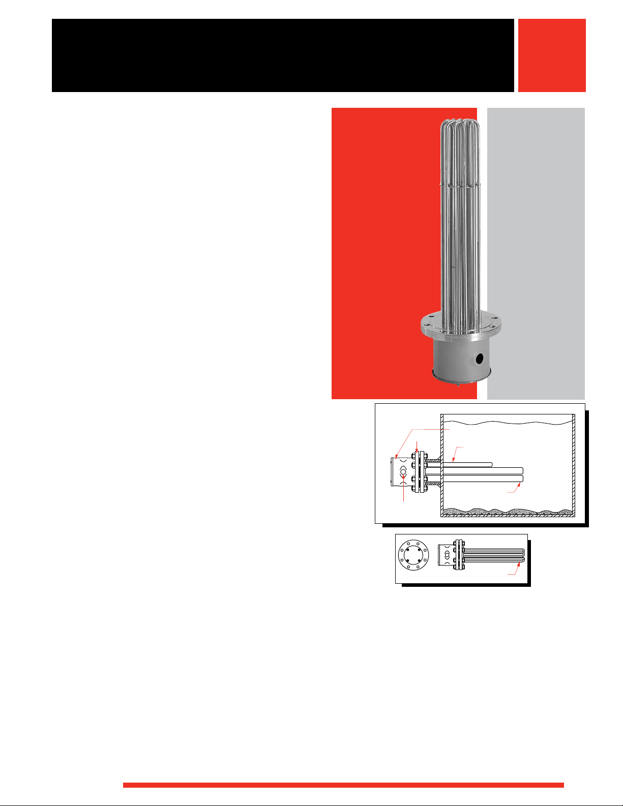
Watlow flange heaters are easy to install and maintain.
Designed for heating liquids and gases in tanks and
pressure vessels, flange immersion heaters are ideal for
applications requiring higher kilowatts.
Watlow flange heaters are made with WATROD or
FIREBAR tubular elements brazed or welded to a flange.
Stock flange heaters are equipped with a general purpose
terminal enclosure.
Flange heaters, with FIREBAR elements, also answer
the need for liquid immersion applications requiring high
kilowatts in small tanks. The FIREBAR element’s unique
flat surface geometry packs more power in a smaller
bundle, with lower watt density, making it especially
well-suited for petroleum-based liquid heating applications.
Performance Capabilities
• Watt densities up to 100 W/in2 (15.5 W/cm2)
• Wattages up to three megawatts
• UL® and CSA component recognition up to 600VAC
• Alloy 800/840 sheath temperatures up to 1600°F
(870°C)
• Passivated 316 stainless steel sheath temperatures up
to 1200°F (650°C)
• 304 stainless steel sheath temperatures up to
1200°F (650°C)
• Steel sheath temperatures up to 750°F (400°C)
• FIREBAR flange heaters deliver more kilowatts in
smaller bundles
• A conventional round tubular 10-inch ANSI flange can
be replaced by a 6-inch ANSI FIREBAR flange with
same immersed length
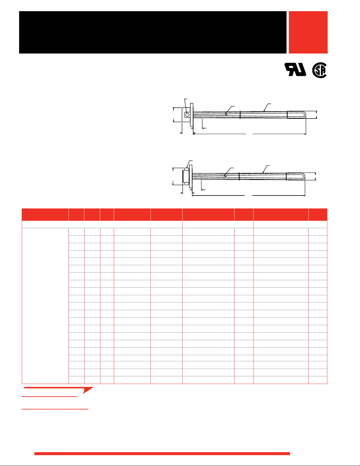
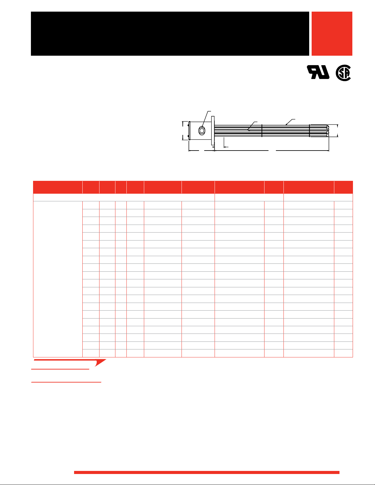
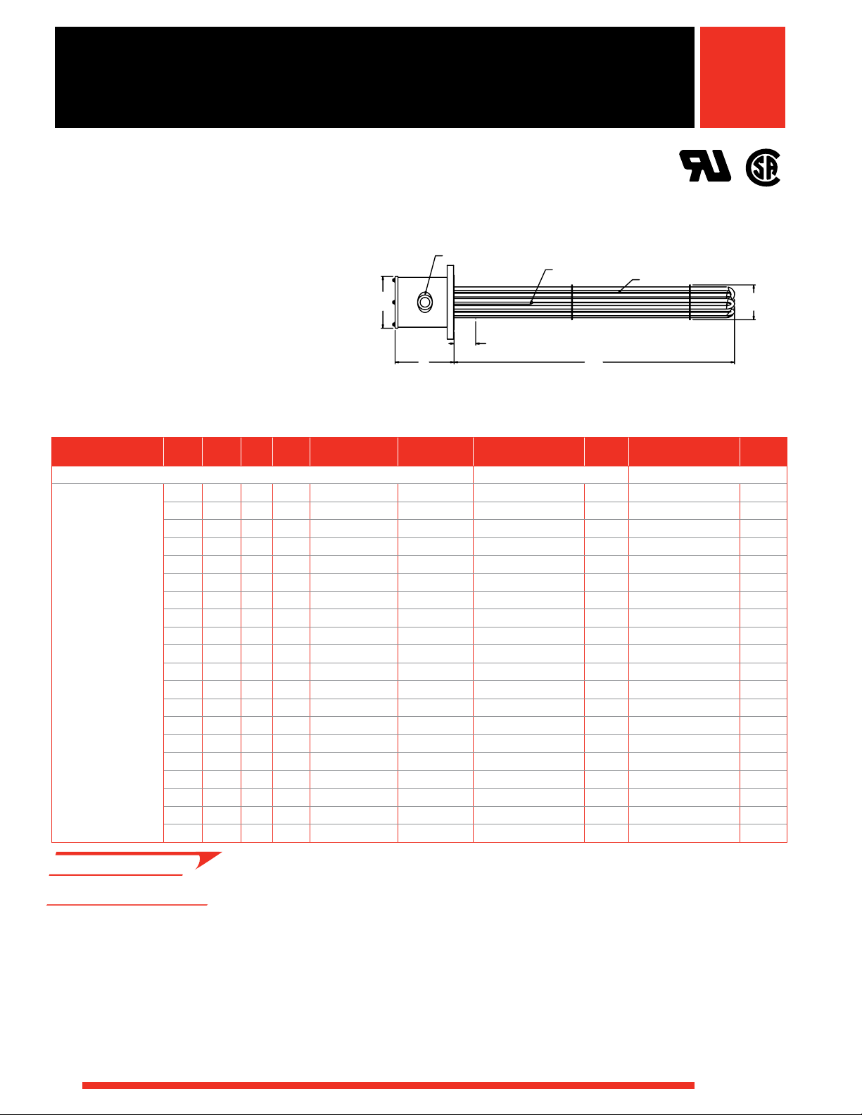
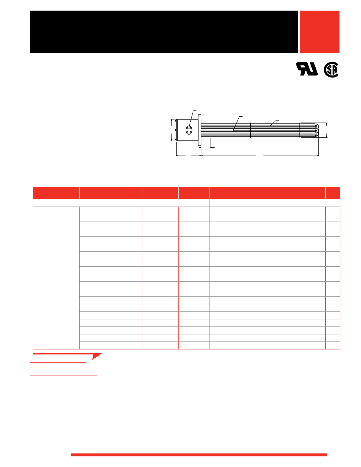
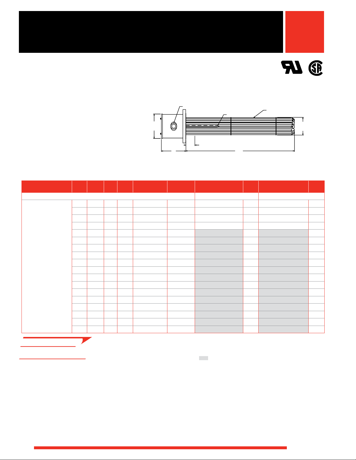
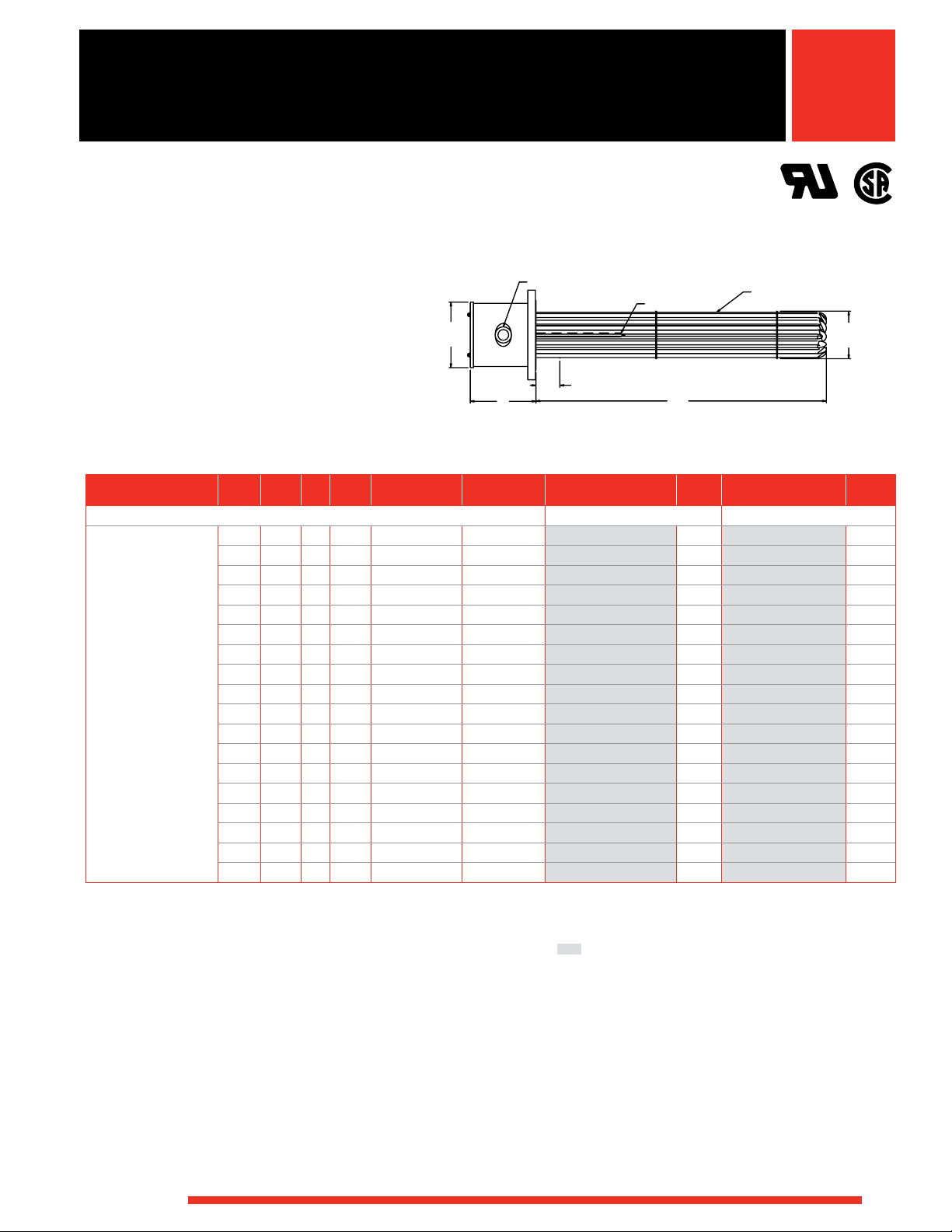
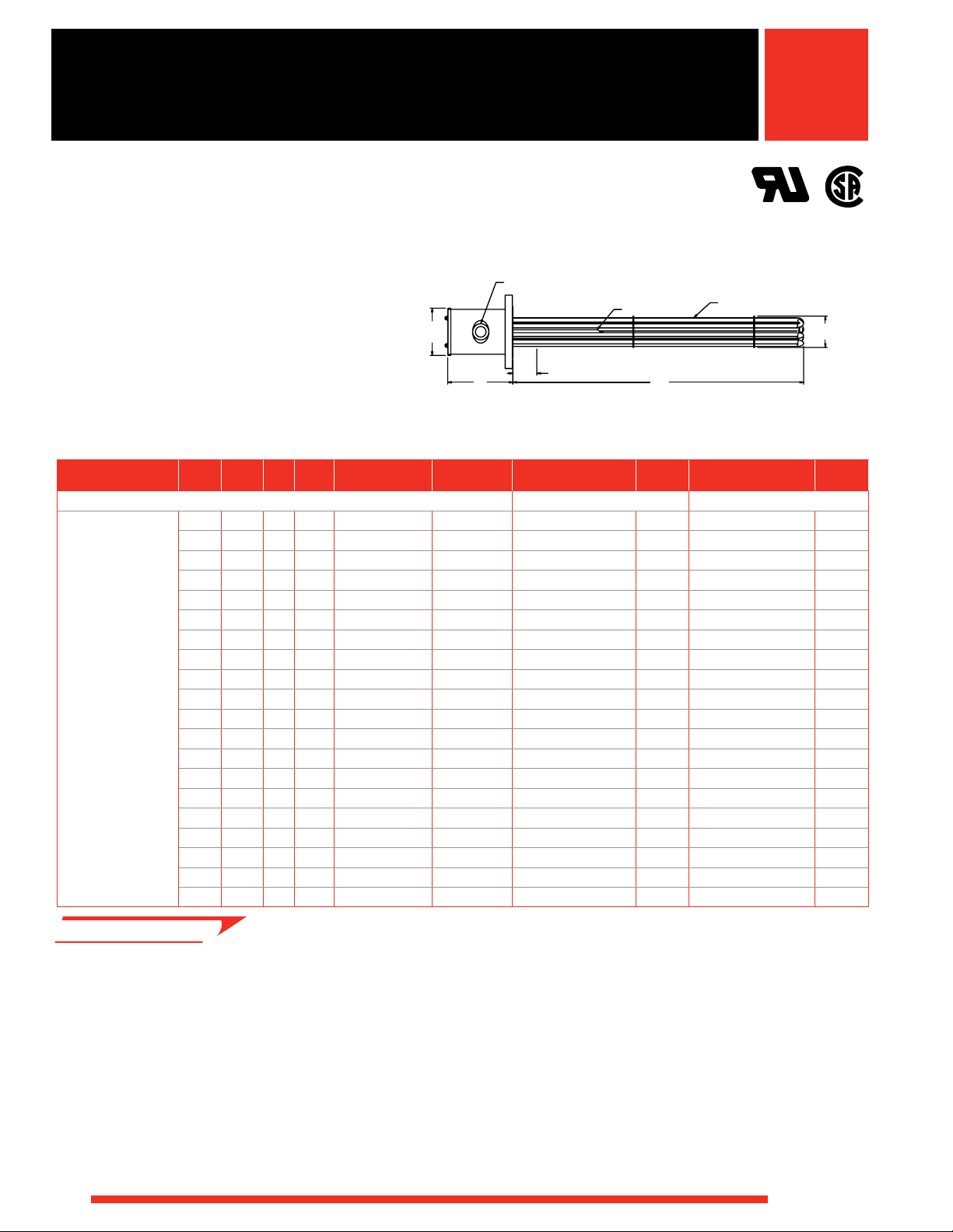
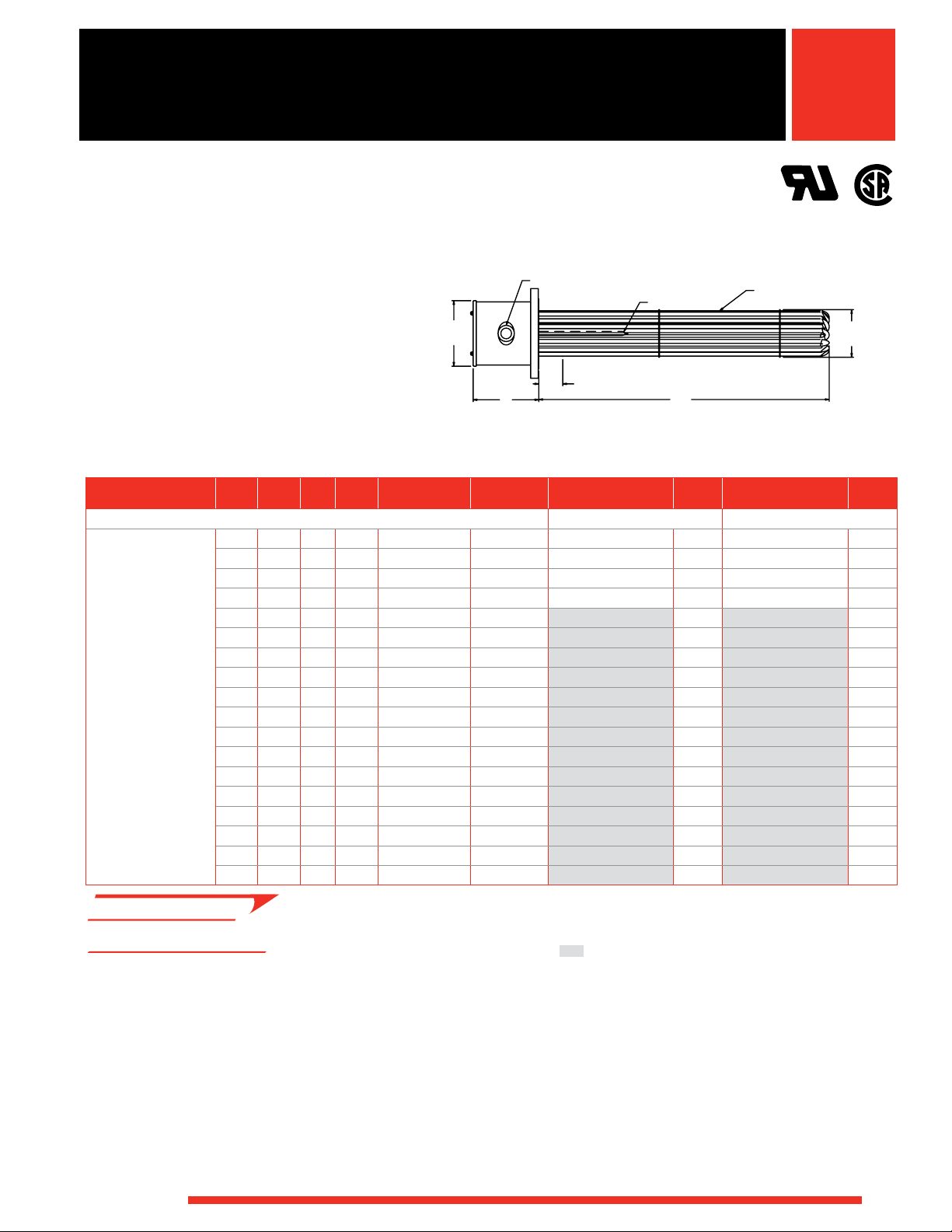
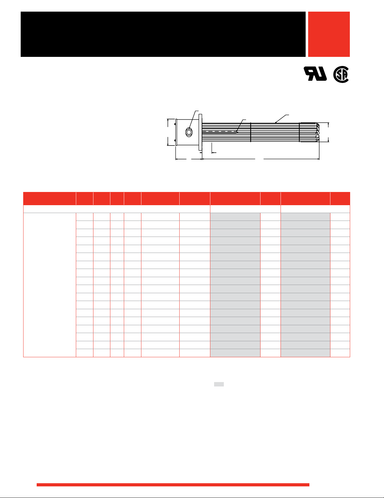
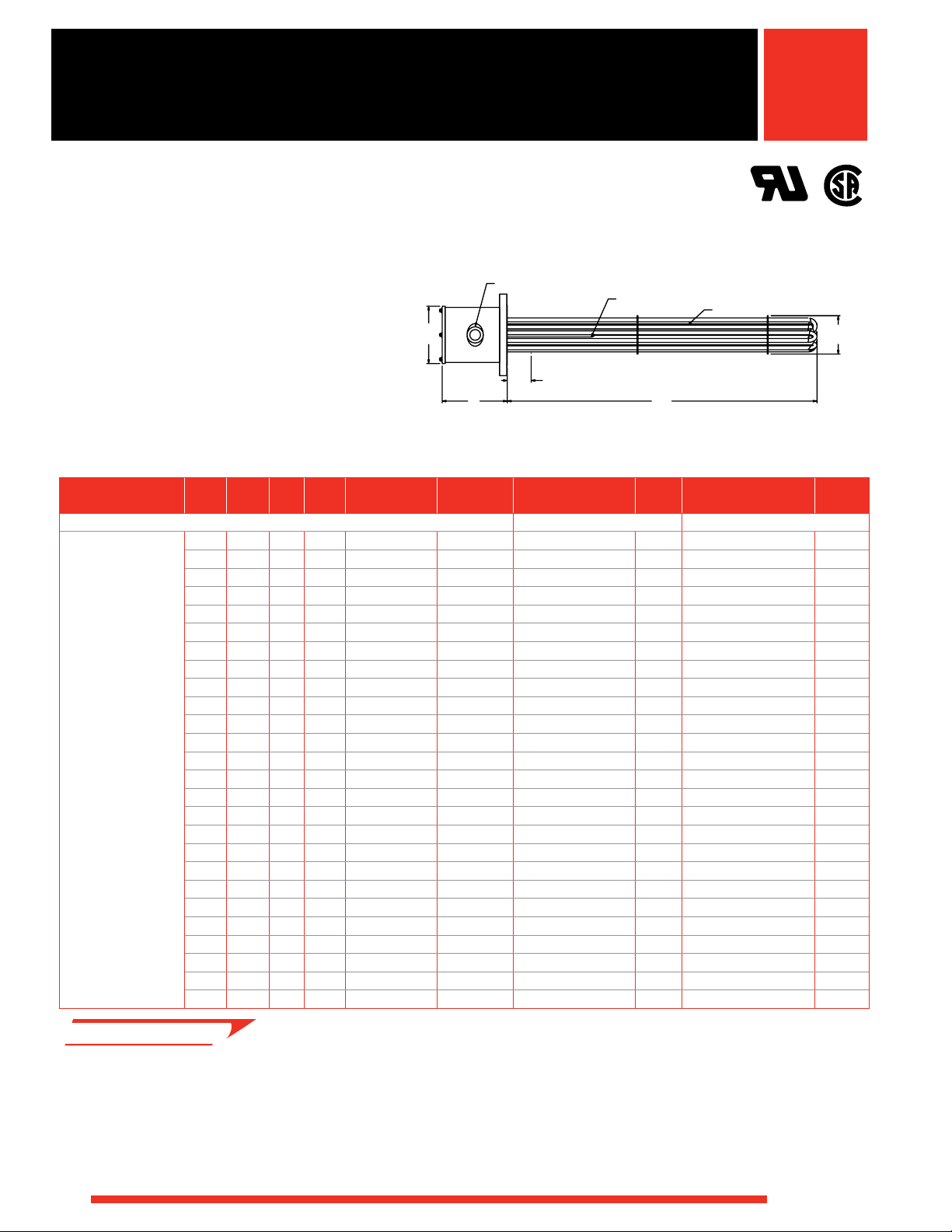
Flange
Conduit Opening
Terminal Enclosure
Thermowell
FIREBAR
Heating Element
Features and Benefits
ANSI and ANSI compatible 2, 21/2, 3 thru 48 inch
flanges
• Provides appropriate heater size-to-application and fit
Element sheath and flange materials
• Meets your application needs
Integral thermowells
• Provides convenient temperature sensor insertion and
replacement without draining the fluid being heated
Standard, general purpose terminal enclosure
• Offers easy access to wiring
WATLOW
®
WATROD Heating Element
Element support(s)
• Provides proper element spacing to maximize heater
performance and life
All units are inspected and/or tested
• Ensures element-to-flange pressure seals do not leak
Drilled and tapped eyebolt holes or lift lugs for eye
bolts on 10 inch and larger flange heaters
• Facilitates lifting during installation
WATROD hairpins are repressed (recompacted)
• Provides improved heater life, insulation resistance and
heat transfer
237
Page 2

Immersion Heaters
WATROD and FIREBAR ANSI Flange
Immersion Heaters
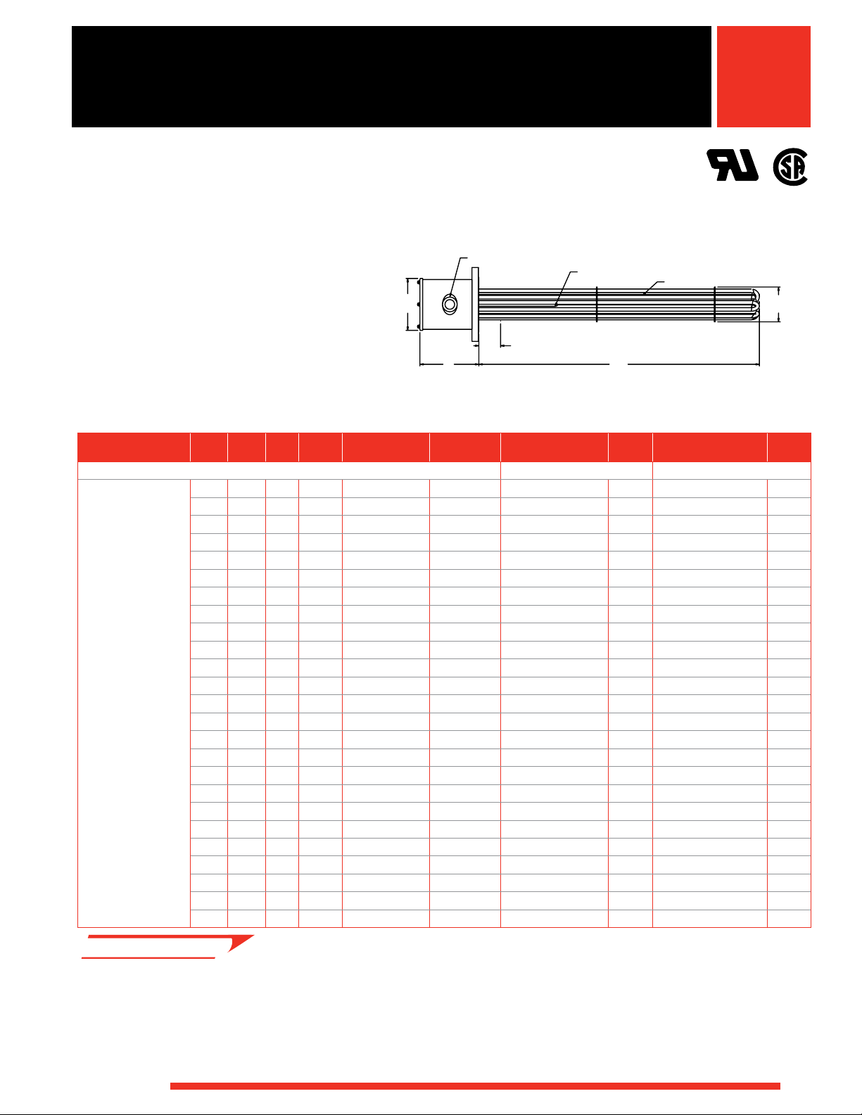
Features and Benefits (Continued)
FIREBAR flange heaters pack more kilowatts into a
smaller bundle
• Includes a conventional round tubular 10 in. (254 mm)
ANSI flange which can be replaced by a 6 in.
(152 mm) ANSI FIREBAR flange with the same
immersed length
Branch circuits are designed for 48 amperes per
circuit maximum
• Reduces risk of failure due to excessive temperatures
generated by high amperage
UL® and CSA component recognition under file
numbers E52951 and 31388 respectively
• Simplifies obtaining third-party recognition for
assembly
Typical Applications
• Water:
Deionized
Demineralized
Clean
Potable
Process
• Industrial water rinse tanks
• Vapor degreasers
• Hydraulic oil, crude, asphalt
• Lubricating oils at API specified watt densities
• Air and gas flow
• Caustic solutions
• Chemical baths
• Process air equipment
• Boiler equipment
• Freeze protection of any fluid
• Anti-freeze (glycol) solutions
• Paraffin
Options
Terminal Enclosures
General purpose terminal enclosures, without
thermostats, are standard on all flange immersion
heaters. Optional terminal enclosures include:
• General purpose with a single or double pole
thermostat.
• Moisture resistant. Available with or without a single
or double pole thermostat.
• Corrosion resistant. Available with or without a single
or double pole thermostat.
• Explosion resistant Class 1, Div. 1 and 2, Groups B, C,
D, T1 - T6. Available with or without a single or double
pole thermostat.
• Explosion/moisture resistant combinations. Available
with or without a single or double pole
thermostat.
Prior to ordering, refer to the terminal enclosure
dimensions on page 243. Order by adding the
appropriate suffix letter(s) to the base flange heater
part number, as shown on the Ordering information chart.
Heater part numbers and suffix letters are depicted on
the charts, pages 244 to 305. Specify class and group,
if applicable.
Caution
Explosion-resistant terminal enclosures are intended
to provide explosion containment in the electrical
termination/wiring enclosure only. No portion of the
assembly outside of this enclosure is covered under
this rating. Rating effectiveness may be compromised
by abuse or misapplication.
238
WATLOW
®
Page 3
Immersion Heaters
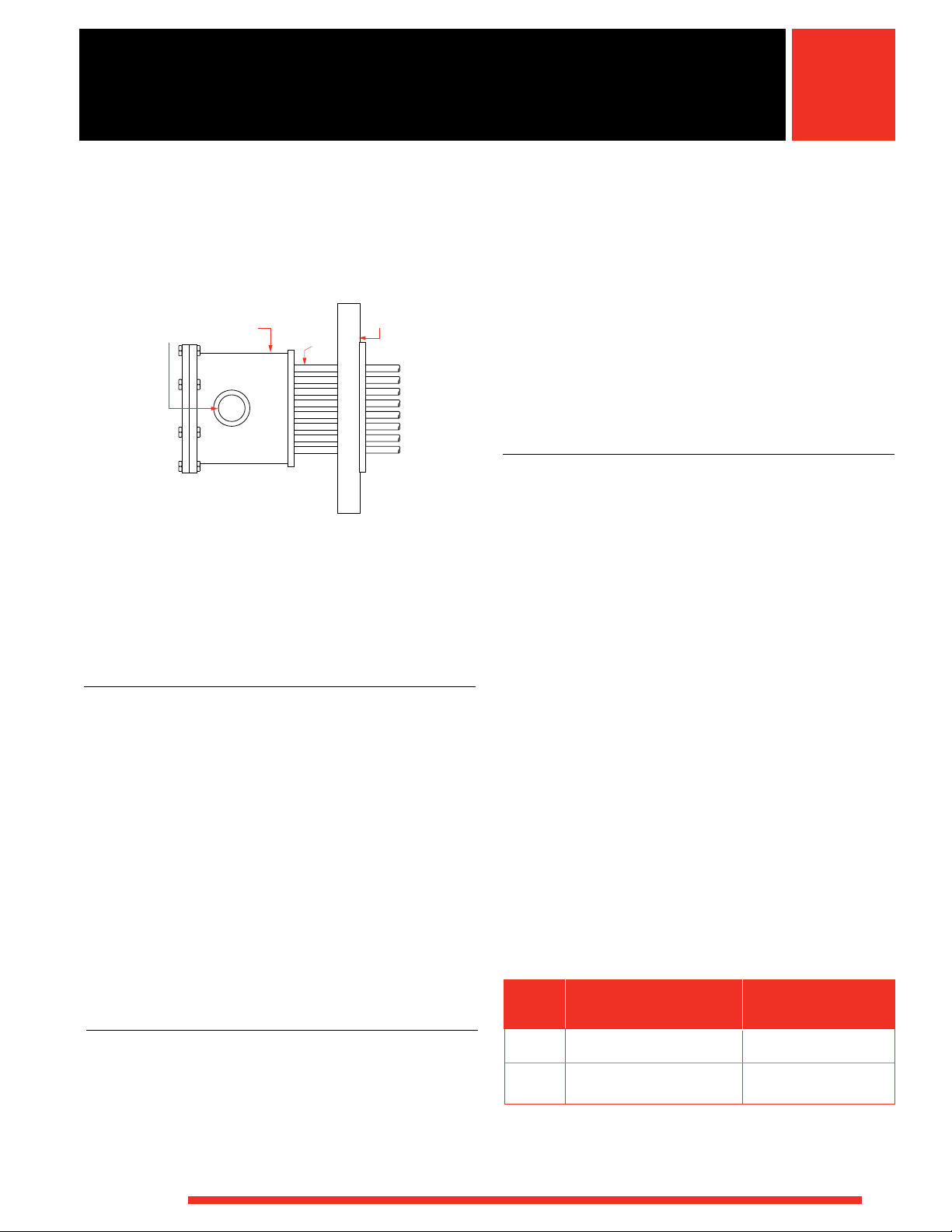
Stand-off
Terminal
Enclosure
Conduit
Openings
Ref. 6 in.
(152 mm)
Stand-off
Height
ANSI
Flange
WATROD and FIREBAR ANSI Flange
Immersion Heaters
Options (Continued)
Stand-off Terminal Enclosures
Ref. 6 in.
Conduit
Openings
Stand-off
Terminal
Enclosure
(150 mm)
Stand-off
Height
Stand-off terminal enclosures provide an air-insulating
barrier between the flange and terminal enclosure by
mounting the terminations and wiring away from the
flange. Stand-off terminal enclosures are recommended
whenever a process operating temperature exceeds
210°F (100°C). This helps minimize terminal enclosure
temperatures.
To order, specify stand-off terminal enclosure.
ANSI
Flange
Certified Enclosures
CSA, ATEX or IECEx certified enclosures protect wiring in
hazardous gas environments. These terminal enclosures,
covered under CSA file number 61707, ATEX certificate
# SIRA 10ATEX1155X or IECEx certificate # IECEx CSA
09.0010X are available on WATROD flange heaters. For
additional information, see page 567 and 568 or contact
your Watlow representative.
For products that will be installed in hazardous locations,
please provide the following information:
• Operating conditions
• Minimum and maximum ambient temperatures for the
installation location
• Mounting orientation
Watlow must understand this information so that an
appropriate design can be provided.
ASME Pressure Vessel Code Welding
Flange assemblies can be provided with an ASME
Section VIII, Div. I pressure vessel stamp upon request.
WATLOW
®
Thermostats
To provide process temperature control, Watlow offers
optional single pole, single throw (SPST) and double pole,
single throw (DPST) thermostats.
Unless otherwise specified, thermostats are mounted
inside the terminal enclosure. For details and ordering
information, refer to Thermostats on pages 534 to 537.
Please verify that the thermostat’s sensing bulb O.D. is
compatible with the flange heater’s thermowell I.D.
Thermocouples
ASTM Type J or K thermocouples offer more accurate
sensing of process and/or sheath temperatures. A
thermocouple may be inserted into the thermowell or
attached to the heater’s sheath.
Thermocouples are supplied with 120 in. (3050 mm)
leads (longer lead lengths available). Unless otherwise
specified, thermocouples are supplied with temperature
ranges detailed on the Thermocouple Types chart.
Using a thermocouple requires an appropriate
temperature and power controller. These must be
purchased separately. Watlow offers a wide variety of
temperature and power controllers to meet virtually all
applications. Temperature controllers can be configured
to accept process variable inputs, too. Contact your
Watlow representative for details.
To order, specify Type J or K thermocouple and lead
length. Indicate if the thermocouple is for process
temperature sensing or heater sheath high-limit
protection. Please specify if the flange heater will be
mounted vertical or horizontal in the tank. If vertical,
specify if the housing is on top or bottom.
If the flange heater is part of an in-line circulation heating
application, indicate flow direction relative to the heater’s
enclosure.
Thermocouple Types
Recommended
ASTM Conductor Characteristics Temperature Range
Type Positive Negative °F (°C)
J Iron Constantan 0 to 1000 (-20 to 540)
(Magnetic) (Non-magnetic)
K Chromel
(Non-magnetic) (Magnetic)
① Type J and Type K thermocouples are rated 32 to 1382°F and
32 to 2282°F (0-750°C and 0-1250°C), respectively. Watlow does
not recommend exceeding temperature ranges shown on this chart
for the tubular product line.
®
Alumel® 0 to 2000 (-20 to 1100)
①
239
Page 4

Immersion Heaters
WATROD and FIREBAR ANSI Flange
Immersion Heaters
Options (Continued)
Wattages and Voltages
Watlow routinely supplies flange immersion heaters with
240 to 480VAC as well as wattages from 150 watts to
one megawatt.
Sheath Materials
The following sheath materials are available on WATROD
and FIREBAR flange heaters:
Standard Sheath Materials
WATROD Alloy 800, 840
316 SS
Steel
FIREBAR Alloy 800
Exotic Sheath Materials
Contact your Watlow representative for details and
availability.
External Finishing
Passivation
During the manufacturing process, particles of iron or
tool steel may become embedded in the stainless steel
or alloy sheath. If not removed, these particles may
corrode, produce rust spots and/or contaminate the
process. For critical sheath applications, passivation
will remove free iron from the sheath. To order,
specify passivation.
Other Finishes
Bright annealing available to meet cosmetic demands.
Flanges
Flange Sizes and Styles
Standard: 2①, 21/2①, 3 to 48 inch ANSI raised face/blind
flanges.
Made-to-Order: 16, 18, 20 and 24 inch in any
recognized configuration, as well as customer specified.
Over 48 inch ANSI flange, contact your Watlow
representative.
Flange Materials
Standard Carbon steel
316 SS
304 SS
Pressure Classes
Standard 150 lb
300 lb
600 lb
① ANSI bolt pattern only
Gaskets
Rubber, asbestos-free and spiral wound gaskets are
available for all flange sizes. Order by specifying gasket
type, flange size/rating, process operating temperature
and pressure.
To make the correct selection, see the Gasket Selection
chart. It provides a recommended gasket type and
effective temperature rating.
To use this chart, multiply operating temperature by the
operating pressure to arrive at “Maximum PSIG x °F.”
This is listed in the chart’s first column.
Gasket Selection
Maximum Temperature
PSIG x °F °F Gasket Type
Up to 15,000 300 Rubber
Over 250,000 700 Asbestos-Free
Over 250,000 ③ Spiral Wound
Gasket
240
③ Depends on metal gasket material.
WATLOW
®
Page 5
Immersion Heaters
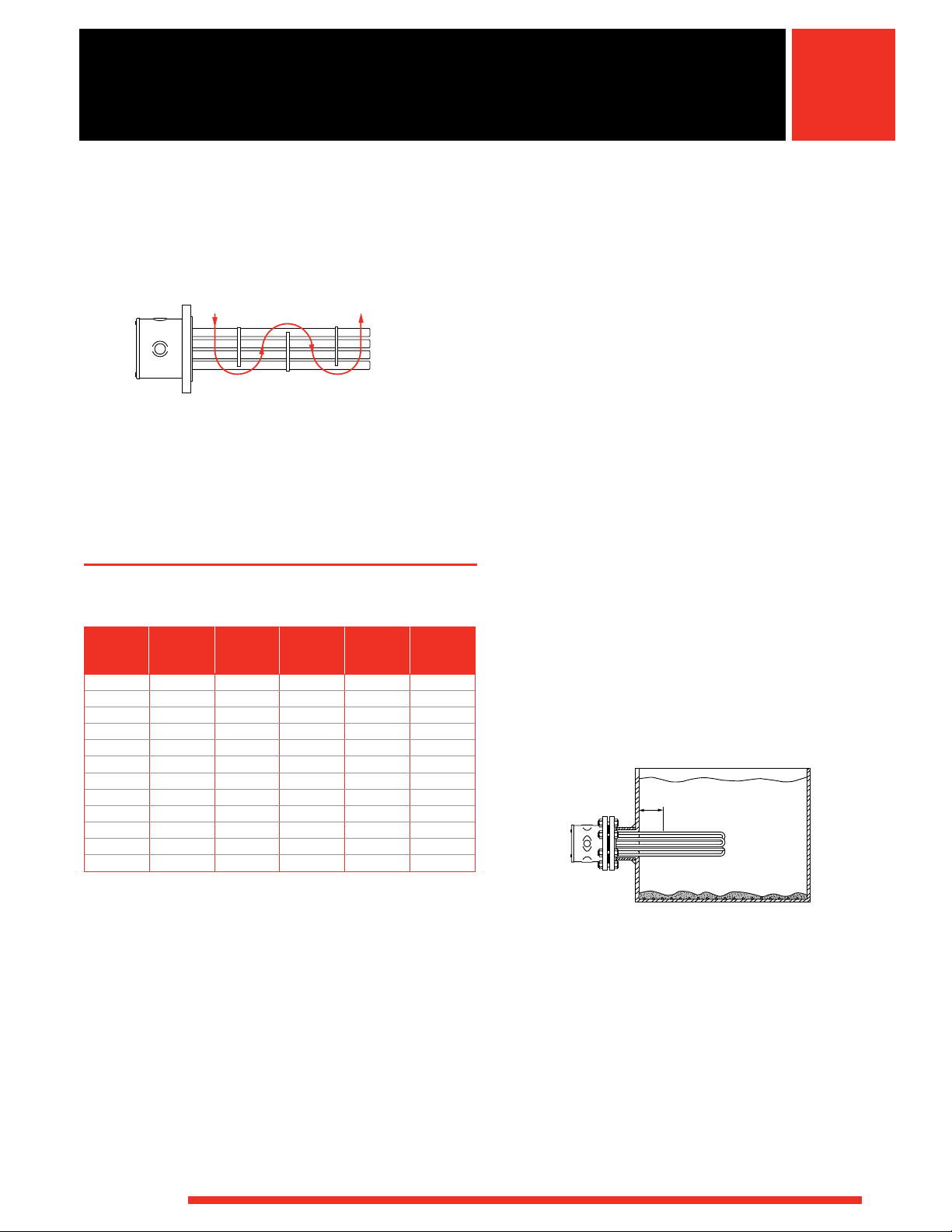
Direction of Flow
WATROD and FIREBAR ANSI Flange
Immersion Heaters
Options (Continued)
Baffles
Direction of Flow
For forced circulation applications, 316 stainless steel
baffles can be arranged on the heating element bundle
to enhance and/or modify fluid or gas flow for better
heat transfer.
For open tank or convection heating applications,
standard element supports will be supplied.
To order, specify baffles.
ANSI Raised Face Blind Flange,
150# Class Dimensions
Pipe Size
3 7.50 0.94 6.00 0.75 4
4 9.00 0.94 7.50 0.75 8
5 10.00 0.94 8.50 0.88 8
6 11.00 1.00 9.50 0.88 8
8 13.50 1.12 11.75 0.88 8
10 16.00 1.19 14.25 1.00 12
12 19.00 1.25 17.00 1.00 12
14 21.00 1.38 18.75 1.12 12
16 23.50 1.44 21.25 1.12 16
18 25.00 1.56 22.75 1.25 16
20 27.50 1.69 25.00 1.25 20
24 32.00 1.88 29.50 1.38 20
Outside
Diameter
Flange
Thickness
Diameter
of Bolt
Circle
Diameter
of Bolt
Holes
Number of
Bolt Holes
Application Hints
• Select the recommended heating element sheath
material and watt density for the substance being
heated. Use the Supplemental Applications Chart on
pages 555 to 560. If unable to determine the correct
heating element sheath material and type, contact your
Watlow representative.
• Extend the element no-heat section completely into
the fluid being heated to help prevent premature heater
failure. See accompanying illustration for proper
no-heat section placement.
• Locate flange heater low in the tank, but above the
sludge level.
• Choose a FIREBAR element when your application
requires a smaller system package or lower watt
density.
• Ensure wiring integrity by keeping terminal enclosure
temperature below 400°F (205°C).
• Size power feeder wires in accordance with National
Electrical Code guidelines and other applicable codes.
• Keep electrical connections clean, dry and tight.
• Minimize problems associated with low liquid level
conditions by using low liquid level sensor or sheath
temperature high-limit control.
No-Heat
Section
WATLOW
• Periodically remove the flange assembly to inspect
and clean the heating element(s). This preventive
maintenance will reduce premature failure and optimize
heater performance.
• Refer to the Installation and Maintenance Instructions
for correct orientation of FIREBAR elements. This is
important in air applications with customer-supplied
circulation tanks. Correct element orientation to flow
minimizes pressure drop and increases buoyancy force
and heater performance.
®
241
Page 6

Immersion Heaters
Extended Capabilities For
WATROD and FIREBAR ANSI Flange
Immersion Heaters
Options
Enclosure Enhancements
• Enclosure heater to solve condensation and freeze
problems.
• Power distribution blocks to facilitate power feed line
wiring.
RTDs
If the process requires greater temperature sensing
accuracy than is possible with thermocouples, Watlow
can also supply RTDs in DIN or JIS calibrations. Contact
your Watlow representative for details.
Wattages and Voltages
If required, Watlow will make heaters with voltage up
to 600VAC and wattage beyond one megawatt. For
more information on special voltage and wattage
configurations, contact your Watlow representative.
xtEndEd
E
apability
C
Flanges
Flange Materials
Extended Exotic materials to
meet specific
application needs ①
Pressure Classes
Extended Over 600 lb ①
① Contact your Watlow representative
Sheath Materials
The following sheath materials are available on WATROD
and FIREBAR flange heaters:
Extended Sheath Materials
WATROD Titanium
304 and 321 SS
Hastelloy C276
Alloy 400 and 600
FIREBAR 304 SS
242
WATLOW
®
Page 7
Immersion Heaters
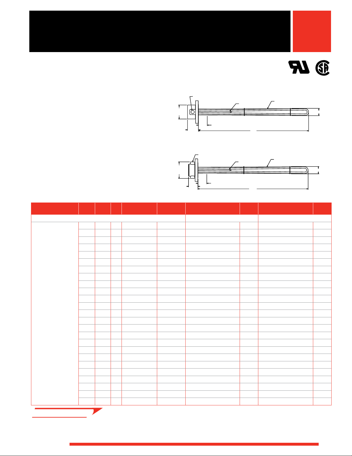
'K'
4" = 7 7/8
5" = 8 7/8
6" = 9 7/8
8" = 12 1/8
10" = 14 5/8
12" = 17 1/4
14" = 19 3/8
75⁄8 in.
(193.7 mm)
5
¾ in.
(146 mm)
7
½ in. Ref.
(191 mm)
“F”
3 in. - 150# ANSI Flange
“D”
3" AND 4" FLANGE
'K'
5" = 8 7/8
6" = 9 7/8
8" = 12 1/8
10" = 14 5/8
12" = 17 1/4
14" = 19 3/8
7½ in. Ref.
(191 mm)
“F”
5
¾ in. Ref.
(146 mm)
7
5⁄8
in.
(193.7 mm)
“D”
95⁄16 in.
(237 mm)
“F”
“D”
“K”
4 in. - 150# ANSI Flange
WATROD and FIREBAR ANSI Flange
Immersion Heaters
Optional Moisture/Explosion Resistant
Enclosure Without Thermostat
Optional Moisture/Explosion Resistant
Enclosure With Thermostat
75⁄8 in.
(193.7 mm)
3 in. - 150# ANSI Flange
“D”
5⁄8
7
in.
(193.7 mm)
¾ in.
5
(146 mm)
7
½ in. Ref.
(191 mm)
“F”
4 to 14 in. - 150# ANSI Flange
“D”
“K”
77⁄8 in.
(200 mm)
“F”
“K”
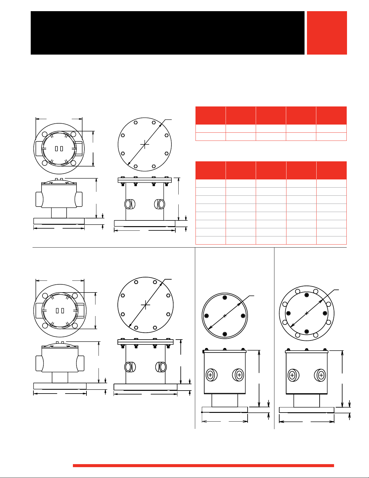
Terminal Enclosure Dimensions
General Purpose & Moisture Resistant Enclosures
ANSI Flange
Size
in.
3
4
“F”
Thickness
in. (mm)
15
/16 (23.8) 53/4
15
/16 (23.8) 53/4
“K”
With
Thermostat
(146)
(146)
“K”
Without
Thermostat
See heater dwg.
See heater dwg.
“D”
in. (mm)
71/2
(191)
9 (229)
Note: 5 thru 12 in. (127 thru 305 mm) flange dimensions are on catalog
heater drawings.
Moisture/Explosion Resistant Enclosures
ANSI Flange
Size
in.
3
4
5
6
8
10
12
14
Optional General
Purpose/Moisture
Resistant Enclosure
“F”
Thickness
in. (mm)
15
/16 (23.8) N/A N/A 71/2 (191)
15
/16 (23.8) N/A
15
/16 (23.8)
1 (25.0)
11/8 (28.6)
13/16 (30.2)
11/4 (32.0)
13/8 (34.9)
“K”
With
Thermostat
“K”
Without
Thermostat
77/8 (200.0)
87/8 (225.4)
97/8 (250.8)
87/8 (225.4)
97/8 (250.8)
121/8 (308.0) 121/8 (308.0)
145/8 (371.5) 145/8
(371.5)
171/4 (438.0) 171/4 (438.0)
193/8 (492.1) 193/8 (492.1)
in. (mm)
9 (229)
10 (254)
11 (280)
131/2
16 (407)
19 (483)
21 (534)
Optional Moisture
Resistant Enclosure
With Thermostat
“D”
(343)
With Thermostat
“K”
“K”
¾
in. Ref.
5
(146 mm)
7½ in. Ref.
(191 mm)
7⁄8 in.
7
(200 mm)
“F”
“D”
3 and 4 in. - 150# ANSI Flange
“D”
5 to 14 in. - 150# ANSI Flange
To order: Reference the Ordering Information on page 306
WATLOW
®
9
5⁄16 in.
“F”
(237 mm)
3 in. - 150# ANSI Flange
Note: Dimensions for all 5 to 14 in. flange heaters with General Purpose
or Moisture Resistant Enclosure with thermostats are identical to units
supplied without thermostats.
“D”
“F”
4 in. - 150# ANSI Flange
“D”
95⁄16 in.
(237 mm)
“F”
243
Page 8
Immersion Heaters
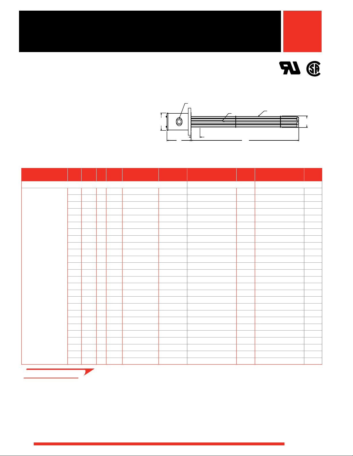
2¾ in. O.D.
(70 mm)
¾ in. NPT Knockout
Thermowell
0.475 in. (12.1 mm)
Dia. Element
4 in. (102 mm) Cold (Ref.)
45⁄8 in.
(117.5 mm)
35⁄8 in. Dia.
(92.1 mm)
“B”
®
WATROD and FIREBAR ANSI Flange
Immersion Heaters
®
Application: Clean Water
• 3 inch - 150 lb ANSI flange.
• WATROD elements
• Without thermostat
• General purpose or
moisture-resistant enclosures
• Single circuit
Description Volts kW Ph
• M - Manufacturing lead times
2
60 W/in
Steel Flange
3-Alloy 800
Elements
(9.3 W/cm2)
120 6.0 1 15
240 6.0 3 15
480 6.0 1 15
480 6.0 3 151/2 (394) 22 (10) FMN715J5S RS FMN715J5W RS
120 9.0 1 211/2 (546) 25 (12) FMN721J10S RS FMN721J10W RS
240 9.0 3 21
480 9.0 1 21
480 9.0 3 21
240 12.0 3 27 (686) 27 (13) FMN727A3S RS FMN727A3W RS
480 12.0 1 27 (686) 27 (13) FMN727A11S RS FMN727A11W RS
480 12.0 3 27 (686) 27 (13) FMN727A5S RS FMN727A5W RS
240 15.0 3 32
480 15.0 1 32
480 15.0 3 32
240 18.0 3 38 (965) 30 (14) FMN738A3S RS FMN738A3W RS
480 18.0 1 38 (965) 30 (14) FMN738A11S RS FMN738A11W RS
480 18.0 3 38 (965) 30 (14) FMN738A5S RS FMN738A5W RS
480 25.0 1 51 (1295) 34 (16) FMN751A11S RS FMN751A11W RS
480 25.0 3 51 (1295) 34 (16) FMN751A5S RS FMN751A5W RS
480 30.0 1 60
480 30.0 3 60
• RS - Next day shipment
up to 5 pieces
General Purpose
45⁄8 in.
(117.5 mm)
35⁄8 in. Dia.
(92.1 mm)
¾ in. NPT Knockout
Thermowell
4 in. (102 mm) Cold (Ref.)
“B”
0.475 in. (12.1 mm)
Dia. Element
Moisture Resistant
(2)
“B” Dim.
in. (mm)
53⁄8 in.
(136.5 mm)
1⁄8 in. Dia.
3
(79.4 mm)
Ship Wt.
lbs (kg)
¾ in. NPT Hubs
Thermowell
4 in. (102 mm) Cold (Ref.)
“B”
Part
Number Del.
0.475 in. (12.1 mm)
Dia. Element
Part
Number Del.
General Purpose Enclosure Moisture-Resistant Enclosure
1
/2 (394) 22 (10) FMN715J10S RS FMN715J10W RS
1
/2 (394) 22 (10) FMN715J3S RS FMN715J3W RS
1
/2 (394) 22 (10) FMN715J11S RS FMN715J11W RS
1
/2 (546) 25 (12) FMN721J3S RS FMN721J3W RS
1
/2 (546) 25 (12) FMN721J11S RS FMN721J11W RS
1
/2 (546) 25 (12) FMN721J5S RS FMN721J5W RS
1
/2 (826) 28 (13) FMN732J3S RS FMN732J3W RS
1
/2 (826) 28 (13) FMN732J11S RS FMN732J11W RS
1
/2 (826) 28 (13) FMN732J5S RS FMN732J5W RS
1
/2 (1537) 36 (17) FMN760J11S M FMN760J11W RS
1
/2 (1537) 36 (17) FMN760J5S M FMN760J5W RS
Notes: • All flange bundles are designed to fit the inside diameter
of the equivalent standard schedule pipe
• For ANSI flange dimensions, reference chart on page 241
2¾ in. O.D.
(70 mm)
2¾ in. O.D.
(70 mm)
244
WATLOW
®
Page 9
Immersion Heaters
4"-150# FLANGE
①
®
WATROD and FIREBAR ANSI Flange
Immersion Heaters
®
Application: Clean Water
• 4 inch - 150 lb ANSI flange
• WATROD element
• Without thermostat
• General purpose or
moisture-resistant enclosures
Description Volts kW Ph#Circ.
60 W/in2
Steel Flange
6-Alloy 800
Elements
(9.3 W/cm2)
• RS - Next day shipment
up to 5 pieces
• M - Manufacturing lead times
240 12.0 1 2 15
240 12.0 3 1 15
480 12.0 1 1 15
480 12.0 3 1 15
240 18.0 1 2 21
240 18.0 3 1 21
480 18.0 1 1 21
480 18.0 3 1 21
240 24.0 1 2 27 (686) 36 (17) FON727A10S RS FON727A10W RS
240 24.0 3 2 27 (686) 36 (17) FON727A3S RS FON727A3W RS
480 24.0 1 1 27 (686) 36 (17) FON727A11S RS FON727A11W RS
480 24.0 3 1 27 (686) 36 (17) FON727A5S RS FON727A5W RS
240 30.0 3 2 32
480 30.0 1 2 32
480 30.0 3 1 32
240 36.0 3 2 38 (965) 43 (20) FON738A3S RS FON738A3W RS
480 36.0 1 2 38 (965) 43 (20) FON738A11S RS FON738A11W RS
480 36.0 3 1 38 (965) 43 (20) FON738A5S RS FON738A5W RS
480 50.0 3 2 51 (1295) 48 (22) FON751A5S RS FON751A5W RS
480 60.0 3 2 60
General Purpose and
Moisture Resistant
0.475 in. (12.1 mm) Dia. Element
5
½
in.
(140 mm)
8 in.
(203 mm)
Thermowell
4 in. (102 mm) Cold (Ref.)
“B”
① The number and size of the conduit opening will comply with the
National Electrical Code® standards.
“B” Dim.
in. (mm)
1
/2 (394) 31 (14) FON715J10S RS FON715J10W RS
1
/2 (394) 31 (14) FON715J3S RS FON715J3W RS
1
/2 (394) 31 (14) FON715J11S RS FON715J11W RS
1
/2 (394) 31 (14) FON715J5S RS FON715J5W RS
1
/2 (546) 34 (16) FON721J10S RS FON721J10W RS
1
/2 (546) 34 (16) FON721J3S RS FON721J3W RS
1
/2 (546) 34 (16) FON721J11S RS FON721J11W RS
1
/2 (546) 34 (16) FON721J5S RS FON721J5W RS
1
/2 (826) 39 (18) FON732J3S RS FON732J3W RS
1
/2 (826) 39 (18) FON732J11S RS FON732J11W RS
1
/2 (826) 39 (18) FON732J5S RS FON732J5W RS
1
/2 (1537) 52 (24) FON760J5S M FON760J5W M
Ship Wt.
lbs (kg)
General Purpose Enclosure
Notes: • All flange bundles are designed to fit the inside diameter
of the equivalent standard schedule pipe
• For ANSI flange dimensions, reference chart on page 241
Part
Number Del.
Part
Number Del.
Moisture-Resistant Enclosure
3
7⁄8 in. O.D.
(98.4 mm)
WATLOW
®
245
Page 10
Immersion Heaters
®
WATROD and FIREBAR ANSI Flange
Immersion Heaters
®
Application: Clean Water
• 5 inch - 150 lb ANSI flange
• WATROD element
• Without thermostat
• General purpose or
moisture-resistant enclosures
Description Volts kW Ph# Circ.
60 W/in2
Steel Flange
6-Alloy 800
Elements
(9.3 W/cm2)
240 12.0 1 2 15
240 12.0 3 1 15
480 12.0 1 1 15
480 12.0 3 1 15
240 18.0 1 2 21
240 18.0 3 1 21
480 18.0 1 1 21
480 18.0 3 1 21
240 24.0 1 3 27 (686) 40 (19) FNN727A10S RS FNN727A10W RS
240 24.0 3 2 27 (686) 40 (19) FNN727A3S RS FNN727A3W RS
480 24.0 1 3 27 (686) 40 (19) FNN727A11S RS FNN727A11W RS
480 24.0 3 1 27 (686) 40 (19) FNN727A5S RS FNN727A5W RS
240 30.0 3 2 32
480 30.0 1 2 32
480 30.0 3 1 32
240 36.0 3 2 38 (965) 47 (22) FNN738A3S RS FNN738A3W RS
480 36.0 1 2 38 (965) 47 (22) FNN738A11S RS FNN738A11W RS
480 36.0 3 1 38 (965) 47 (22) FNN738A5S RS FNN738A5W RS
480 50.0 3 2 51 (1295) 52 (24) FNN751A5S RS FNN751A5W RS
480 60.0 3 2 60
General Purpose and
Moisture Resistant
7 in.
(178 mm)
8 in. O.D.
(203 mm)
①
4 in. (102 mm) Cold (Ref.)
Thermowell
“B”
0.475 in. (12.1 mm) Dia. Element
① The number and size of the conduit opening will comply with the
National Electrical Code® standards.
“B” Dim.
in. (mm)
1
/2 (394) 35 (16) FNN715J10S RS FNN715J10W RS
1
/2 (394) 35 (16) FNN715J3S RS FNN715J3W RS
1
/2 (394) 35 (16) FNN715J11S RS FNN715J11W RS
1
/2 (394) 35 (16) FNN715J5S RS FNN715J5W RS
1
/2 (546) 38 (18) FNN721J10S RS FNN721J10W RS
1
/2 (546) 38 (18) FNN721J3S RS FNN721J3W RS
1
/2 (546) 38 (18) FNN721J11S RS FNN721J11W RS
1
/2 (546) 38 (18) FNN721J5S RS FNN721J5W RS
1
/2 (826) 43 (20) FNN732J3S RS FNN732J3W RS
1
/2 (826) 43 (20) FNN732J11S RS FNN732J11W RS
1
/2 (826) 43 (20) FNN732J5S RS FNN732J5W RS
1
/2 (1537) 56 (26) FNN760J5S M FNN760J5W M
Ship Wt.
lbs (kg)
Part
Number Del.
General Purpose Enclosure
Part
Number
Moisture-Resistant Enclosure
4¾ in. O.D.
(121 mm)
Del.
• RS - Next day shipment
up to 5 pieces
• M - Manufacturing lead times
246
Notes: • All flange bundles are designed to fit the inside diameter
of the equivalent standard schedule pipe
• For ANSI flange dimensions, reference chart on page 241
WATLOW
®
Page 11
Immersion Heaters
®
WATROD and FIREBAR ANSI Flange
Immersion Heaters
®
Application: Clean Water
• 5 inch - 150 lb ANSI flange
• WATROD element
• Without thermostat
• General purpose or
moisture-resistant enclosures
Description Volts kW Ph#Circ.
60 W/in2
Steel Flange
9-Alloy 800
Elements
(9.3 W/cm2)
• RS - Next day shipment
up to 5 pieces
• M - Manufacturing lead times
240 18.0 1 3 15
240 18.0 3 1 15
480 18.0 1 1 15
480 18.0 3 1 15
240 27.0 1 3 21
240 27.0 3 3 21
480 27.0 1 3 21
480 27.0 3 1 21
240 36.0 3 3 27 (686) 45 (21) FNN727A3XS RS FNN727A3XW RS
480 36.0 1 3 27 (686) 45 (21) FNN727A11XS RS FNN727A11XW RS
480 36.0 3 1 27 (686) 45 (21) FNN727A5XS RS FNN727A5XW RS
240 45.0 3 3 32
480 45.0 1 3 32
480 45.0 3 3 32
240 54.0 3 3 38 (965) 53 (24) FNN738A3XS RS FNN738A3XW RS
480 54.0 1 3 38 (965) 53 (24) FNN738A11XS RS FNN738A11XW RS
480 54.0 3 3 38 (965) 53 (24) FNN738A5XS RS FNN738A5XW RS
480 75.0 3 3 51 (1295) 60 (28) FNN751A5XS RS FNN751A5XW RS
480 90.0 3 3 60
General Purpose and
Moisture Resistant
7 in.
(178 mm)
8 in. O.D.
(203 mm)
①
4 in. (102 mm) Cold (Ref.)
Thermowell
“B”
0.475 in. (12.1 mm) Dia. Element
① The number and size of the conduit opening will comply with the
National Electrical Code® standards.
“B” Dim.
in. (mm)
1
/2 (394) 38 (18) FNN715J10XS RS FNN715J10XW RS
1
/2 (394) 38 (18) FNN715J3XS RS FNN715J3XW RS
1
/2 (394) 38 (18) FNN715J11XS RS FNN715J11XW RS
1
/2 (394) 38 (18) FNN715J5XS RS FNN715J5XW RS
1
/2 (546) 42 (19) FNN721J10XS RS FNN721J10XW RS
1
/2 (546) 42 (19) FNN721J3XS RS FNN721J3XW RS
1
/2 (546) 42 (19) FNN721J11XS RS FNN721J11XW RS
1
/2 (546) 42 (19) FNN721J5XS RS FNN721J5XW RS
1
/2 (826) 48 (22) FNN732J3XS RS FNN732J3XW RS
1
/2 (826) 48 (22) FNN732J11XS RS FNN732J11XW RS
1
/2 (826) 48 (22) FNN732J5XS RS FNN732J5XW RS
1
/2 (1537) 66 (30) FNN760J5XS M FNN760J5XW M
Ship Wt.
lbs (kg)
Notes: • All flange bundles are designed to fit the inside diameter
of the equivalent standard schedule pipe
• For ANSI flange dimensions, reference chart on page 241
Part
Number Del.
General Purpose Enclosure
Part
Number
Moisture-Resistant Enclosure
4¾ in. O.D.
(121 mm)
Del.
WATLOW
®
247
Page 12
Immersion Heaters
4¾ in. O.D.
(121 mm)
Thermowell
1 in. (25 mm)
FIREBAR Element
4 in. (102 mm) Cold (Ref.)
“B”
8 in. O.D.
(203 mm)
7 in.
(178 mm)
0.475 in. (12.1 mm) Dia. Element
①
®
WATROD and FIREBAR ANSI Flange
Immersion Heaters
Application: Clean Water
• 6 inch - 150 lb ANSI flange
• WATROD element
• Without thermostat
• General purpose or
moisture-resistant enclosures
Description Volts kW Ph#Circ.
60 W/in2
Steel Flange
12-Alloy 800
Elements
(9.3 W/cm2)
• RS - Next day shipment
up to 2 pieces
• M - Manufacturing lead times
240 24.0 1 3 15
240 24.0 3 2 15
480 24.0 1 2 15
480 24.0 3 1 15
240 36.0 1 4 21
240 36.0 3 2 21
480 36.0 1 2 21
480 36.0 3 1 21
240 48.0 3 4 26
480 48.0 1 3 26
480 48.0 3 2 26
240 60.0 3 4 32
480 60.0 1 3 32
480 60.0 3 2 32
240 72.0 3 4 37
480 72.0 3 2 37
480 100.0 3 4 50
480 120.0 3 4 60
“B” Dim.
in. (mm)
3
3
3
3
3
3
3
3
7
7
7
3
3
3
7
7
7
3
General Purpose and
Moisture Resistant
8 in.
(203 mm)
(203 mm)
① The number and size of the conduit opening will comply with the
/8 (390.5) 73 (33) FPN715G10S RS FPN715G10W RS
/8 (390.5) 73 (33) FPN715G3S RS FPN715G3W RS
/8 (390.5) 73 (33) FPN715G11S RS FPN715G11W RS
/8 (390.5) 73 (33) FPN715G5S RS FPN715G5W RS
/8 (542.9) 78 (36) FPN721G10S M FPN721G10W M
/8 (542.9) 78 (36) FPN721G3S M FPN721G3W M
/8 (542.9) 78 (36) FPN721G11S M FPN721G11W M
/8 (542.9) 78 (36) FPN721G5S M FPN721G5W M
/8 (682.6) 81 (37) FPN726R3S M FPN726R3W M
/8 (682.6) 81 (37) FPN726R11S M FPN726R11W M
/8 (682.6) 81 (37) FPN726R5S M FPN726R5W M
/8 (822.3) 85 (39) FPN732G3S M FPN732G3W M
/8 (822.3) 85 (39) FPN732G11S M FPN732G11W M
/8 (822.3) 85 (39) FPN732G5S M FPN732G5W M
/8 (962.0) 92 (42) FPN737R3S M FPN737R3W M
/8 (962.0) 92 (42) FPN737R5S M FPN737R5W M
/8 (1292.2) 100 (45) FPN750R5S M FPN750R5W M
/8 (1533.5) 110 (50) FPN760G5S M FPN760G5W M
8 in.
①
Thermowell
4 in. (102 mm) Cold (Ref.)
“B”
0.475 in. (12.1 mm) Dia. Element
National Electrical Code® standards.
Ship Wt.
lbs (kg)
General Purpose Enclosure
Part
Number Del.
Part
Number
Moisture-Resistant Enclosure
Notes: • All flange bundles are designed to fit the inside diameter
of the equivalent standard schedule pipe
• For ANSI flange dimensions, reference chart on page 241
Truck Shipment only
7⁄8 in. O.D.
5
(149.2 mm)
®
Del.
248
WATLOW
®
Page 13
Immersion Heaters
4¾ in. O.D.
(121 mm)
Thermowell
1 in. (25 mm)
FIREBAR Element
4 in. (102 mm) Cold (Ref.)
“B”
8 in. O.D.
(203 mm)
7 in.
(178 mm)
0.475 in. (12.1 mm) Dia. Element
①
®
WATROD and FIREBAR ANSI Flange
Immersion Heaters
Application: Clean Water
• 6 inch - 150 lb ANSI flange
• WATROD element
• Without thermostat
• General purpose or
moisture-resistant enclosures
Description Volts kW Ph#Circ.
60 W/in2
Steel Flange
15-Alloy 800
Elements
(9.3 W/cm
2
)
• M - Manufacturing lead times
240 30.0 1 3 15
240 30.0 3 5 15
480 30.0 1 3 15
480 30.0 3 1 15
240 45.0 1 5 21
240 45.0 3 5 21
480 45.0 1 3 21
480 45.0 3 5 21
240 60.0 3 5 26
480 60.0 1 3 26
480 60.0 3 5 26
240 75.0 3 5 32
480 75.0 1 5 32
480 75.0 3 5 32
240 90.0 3 5 37
480 90.0 3 5 37
480 125.0 3 5 50
480 150.0 3 5 60
(203 mm)
“B” Dim.
in. (mm)
3
/8 (390.5) 76 (35) FPN715G10XS M FPN715G10XW M
3
/8 (390.5) 76 (35) FPN715G3XS M FPN715G3XW M
3
/8 (390.5) 76 (35) FPN715G11XS M FPN715G11XW M
3
/8 (390.5) 76 (35) FPN715G5XS M FPN715G5XW M
3
/8 (542.9) 82 (38) FPN721G10XS M FPN721G10XW M
3
/8 (542.9) 82 (38) FPN721G3XS M FPN721G3XW M
3
/8 (542.9) 82 (38) FPN721G11XS M FPN721G11XW M
3
/8 (542.9) 82 (38) FPN721G5XS M FPN721G5XW M
7
/8 (682.6) 85 (39) FPN726R3XS M FPN726R3XW M
7
/8 (682.6) 85 (39) FPN726R11XS M FPN726R11XW M
7
/8 (682.6) 85 (39) FPN726R5XS M FPN726R5XW M
3
/8 (822.3) 90 (41) FPN732G3XS M FPN732G3XW M
3
/8 (822.3) 90 (41) FPN732G11XS M FPN732G11XW M
3
/8 (822.3) 90 (41) FPN732G5XS M FPN732G5XW M
7
/8 (962.0) 98 (45) FPN737R3XS M FPN737R3XW M
7
/8 (962.0) 98 (45) FPN737R5XS M FPN737R5XW M
7
/8 (1292.2) 108 (49) FPN750R5XS M FPN750R5XW M
3
/8 (1533.5) 120 (55) FPN760G5XS M FPN760G5XW M
General Purpose and
Moisture Resistant
8 in.
8 in.
(203 mm)
①
Thermowell
4 in. (102 mm) Cold (Ref.)
“B”
0.475 in. (12.1 mm) Dia. Element
① The number and size of the conduit opening will comply with the
National Electrical Code® standards.
Ship Wt.
lbs (kg)
Notes: • All flange bundles are designed to fit the inside diameter
of the equivalent standard schedule pipe
• For ANSI flange dimensions, reference chart on page 241
Part
Number Del.
General Purpose Enclosure
Truck Shipment only
Part
Number
Moisture-Resistant Enclosure
7⁄8 in. O.D.
5
(149.2 mm)
Del.
®
WATLOW
®
249
Page 14
WATLOW
®
Immersion Heaters
4"-150# FLANGE
®
WATROD and FIREBAR ANSI Flange
Immersion Heaters
®
Application: Deionized or
Demineralized Water
• 4 inch - 150 lb ANSI flange
• WATROD element
• Without thermostat
• General purpose or
moisture-resistant enclosures
Description Volts kW Ph#Circ.
60 W/in2
316 SS Flange
6-316 SS Elements
(9.3 W/cm2)
Passivated
• RS - Next day shipment
up to 5 pieces
240 12.0 1 2 16 (406) 31 (14) FOR716A10S RS FOR716A10W RS
240 12.0 3 1 16 (406) 31 (14) FOR716A3S RS FOR716A3W RS
480 12.0 1 1 16 (406) 31 (14) FOR716A11S RS FOR716A11W RS
480 12.0 3 1 16 (406) 31 (14) FOR716A5S RS FOR716A5W RS
240 18.0 1 2 22 (559) 34 (16) FOR722A10S RS FOR722A10W RS
240 18.0 3 1 22 (559) 34 (16) FOR722A3S RS FOR722A3W RS
480 18.0 1 1 22 (559) 34 (16) FOR722A11S RS FOR722A11W RS
480 18.0 3 1 22 (559) 34 (16) FOR722A5S RS FOR722A5W RS
240 24.0 1 2 27
240 24.0 3 2 27
480 24.0 1 1 27
480 24.0 3 1 27
240 30.0 3 2 33 (838) 39 (18) FOR733A3S RS FOR733A3W RS
480 30.0 1 2 33 (838) 39 (18) FOR733A11S RS FOR733A11W RS
480 30.0 3 1 33 (838) 39 (18) FOR733A5S RS FOR733A5W RS
240 36.0 3 2 38
480 36.0 1 2 38
480 36.0 3 1 38
480 50.0 3 2 51
480 60.0 3 2 61 (1549) 52 (24) FOR761A5S RS FOR761A5W RS
General Purpose and
Moisture Resistant
①
0.475 in. (12.1 mm) Dia. Element
5
½ in.
(140 mm)
8 in.
(203 mm)
Thermowell
4 in. (102 mm) Cold (Ref.)
“B”
① The number and size of the conduit opening will comply with the
National Electrical Code® standards.
“B” Dim.
in. (mm)
1
/2 (699) 36 (17) FOR727J10S RS FOR727J10W RS
1
/2 (699) 36 (17) FOR727J3S RS FOR727J3W RS
1
/2 (699) 36 (17) FOR727J11S RS FOR727J11W RS
1
/2 (699) 36 (17) FOR727J5S RS FOR727J5W RS
1
/2 (978) 43 (20) FOR738J3S RS FOR738J3W RS
1
/2 (978) 43 (20) FOR738J11S RS FOR738J11W RS
1
/2 (978) 43 (20) FOR738J5S RS FOR738J5W RS
1
/2 (1308) 48 (22) FOR751J5S RS FOR751J5W RS
Ship Wt.
lbs (kg)
Notes: • All flange bundles are designed to fit the inside diameter
of the equivalent standard schedule pipe
• For ANSI flange dimensions, reference chart on page 241
Part
Number Del.
General Purpose Enclosure
Part
Number Del.
Moisture-Resistant Enclosure
3
7⁄8 in. O.D.
(98.4 mm)
250
Page 15
WATLOW
®
Immersion Heaters
4¾ in. O.D.
(121 mm)
Thermowell
1 in. (25 mm)
FIREBAR Element
4 in. (102 mm) Cold (Ref.)
“B”
8 in. O.D.
(203 mm)
7 in.
(178 mm)
0.475 in. (12.1 mm) Dia. Element
①
®
WATROD and FIREBAR ANSI Flange
Immersion Heaters
®
Application: Deionized or
Demineralized Water
• 6 inch - 150 lb ANSI flange
• WATROD element
• Without thermostat
• General purpose or
moisture-resistant enclosures
Description Volts kW Ph#Circ.
60 W/in2
316 SS Flange
12-316 SS Elements
(9.3 W/cm2)
(Passivated)
• RS - Next day shipment
up to 2 pieces
• M - Manufacturing lead times
240 24.0 1 3 15
240 24.0 3 2 15
480 24.0 1 2 15
480 24.0 3 1 15
240 36.0 1 4 21
240 36.0 3 2 21
480 36.0 1 2 21
480 36.0 3 1 21
240 48.0 3 4 27
480 48.0 1 3 27
480 48.0 3 2 27
240 60.0 3 4 32
480 60.0 1 3 32
480 60.0 3 2 32
240 72.0 3 4 38
480 72.0 3 2 38
480 100.0 3 4 51
480 120.0 3 4 60
General Purpose and
Moisture Resistant
8 in.
(203 mm)
① The number and size of the conduit opening will comply with the
“B” Dim.
in. (mm)
3
/4 (400) 73 (33) FPR715N10S RS FPR715N10W RS
3
/4 (400) 73 (33) FPR715N3S RS FPR715N3W RS
3
/4 (400) 73 (33) FPR715N11S RS FPR715N11W RS
3
/4 (400) 73 (33) FPR715N5S RS FPR715N5W RS
3
/4 (552) 78 (36) FPR721N10S M FPR721N10W M
3
/4 (552) 78 (36) FPR721N3S M FPR721N3W M
3
/4 (552) 78 (36) FPR721N11S M FPR721N11W M
3
/4 (552) 78 (36) FPR721N5S M FPR721N5W M
1
/4 (692) 81 (37) FPR727E3S M FPR727E3W M
1
/4 (692) 81 (37) FPR727E11S M FPR727E11W M
1
/4 (692) 81 (37) FPR727E5S M FPR727E5W M
3
/4 (832) 85 (39) FPR732N3S M FPR732N3W M
3
/4 (832) 85 (39) FPR732N11S M FPR732N11W M
3
/4 (832) 85 (39) FPR732N5S M FPR732N5W M
1
/4 (972) 92 (42) FPR738E3S M FPR738E3W M
1
/4 (972) 92 (42) FPR738E5S M FPR738E5W M
1
/4 (1302) 100 (45) FPR751E5S M FPR751E5W M
3
/4 (1543) 110 (50) FPR760N5S M FPR760N5W M
8 in.
(203 mm)
①
Thermowell
4 in. (102 mm) Cold (Ref.)
“B”
0.475 in. (12.1 mm) Dia. Element
National Electrical Code® standards.
Ship Wt.
lbs (kg)
Part
Number Del.
General Purpose Enclosure
Part
Number
Moisture-Resistant Enclosure
Notes: • All flange bundles are designed to fit the inside diameter
of the equivalent standard schedule pipe
• For ANSI flange dimensions, reference chart on page 241
Truck Shipment only
7⁄8 in. O.D.
5
(149.2 mm)
Del.
251
Page 16
WATLOW
®
Immersion Heaters
4¾ in. O.D.
(121 mm)
Thermowell
1 in. (25 mm)
FIREBAR Element
4 in. (102 mm) Cold (Ref.)
“B”
8 in. O.D.
(203 mm)
7 in.
(178 mm)
0.475 in. (12.1 mm) Dia. Element
①
®
WATROD and FIREBAR ANSI Flange
Immersion Heaters
®
Application: Deionized or
Demineralized Water
• 6 inch - 150 lb ANSI flange
• WATROD element
• Without thermostat
• General purpose or
moisture-resistant enclosures
Description Volts kW Ph#Circ.
60 W/in2
316 SS Flange
15-316 SS Elements
(9.3 W/cm2)
(Passivated)
• M - Manufacturing lead times
240 30.0 1 3 15
240 30.0 3 5 15
480 30.0 1 3 15
480 30.0 3 1 15
240 45.0 1 5 21
240 45.0 3 5 21
480 45.0 1 3 21
480 45.0 3 5 21
240 60.0 3 5 27
480 60.0 1 3 27
480 60.0 3 5 27
240 75.0 3 5 32
480 75.0 1 5 32
480 75.0 3 5 32
240 90.0 3 5 38
480 90.0 3 5 38
480 125.0 3 5 51
480 150.0 3 5 60
General Purpose and
Moisture Resistant
8 in.
(203 mm)
8 in.
(203 mm)
① The number and size of the conduit opening will comply with the
National Electrical Code® standards.
“B” Dim.
in. (mm)
3
/4 (400) 76 (35) FPR715N10XS M FPR715N10XW M
3
/4 (400) 76 (35) FPR715N3XS M FPR715N3XW M
3
/4 (400) 76 (35) FPR715N11XS M FPR715N11XW M
3
/4 (400) 76 (35) FPR715N5XS M FPR715N5XW M
3
/4 (552) 82 (38) FPR721N10XS M FPR721N10XW M
3
/4 (552) 82 (38) FPR721N3XS M FPR721N3XW M
3
/4 (552) 82 (38) FPR721N11XS M FPR721N11XW M
3
/4 (552) 82 (38) FPR721N5XS M FPR721N5XW M
1
/4 (692) 85 (39) FPR727E3XS M FPR727E3XW M
1
/4 (692) 85 (39) FPR727E11XS M FPR727E11XW M
1
/4 (692) 85 (39) FPR727E5XS M FPR727E5XW M
3
/4 (832) 90 (41) FPR732N3XS M FPR732N3XW M
3
/4 (832) 90 (41) FPR732N11XS M FPR732N11XW M
3
/4 (832) 90 (41) FPR732N5XS M FPR732N5XW M
1
/4 (972) 98 (45) FPR738E3XS M FPR738E3XW M
1
/4 (972) 98 (45) FPR738E5XS M FPR738E5XW M
1
/4 (1302) 108 (49) FPR751E5XS M FPR751E5XW M
3
/4 (1543) 120 (55) FPR760N5XS M FPR760N5XW M
Ship Wt.
lbs (kg)
①
Thermowell
4 in. (102 mm) Cold (Ref.)
“B”
Part
Number Del.
General Purpose Enclosure
0.475 in. (12.1 mm) Dia. Element
7⁄8 in. O.D.
5
(149.2 mm)
Part
Number
Moisture-Resistant Enclosure
Notes: • All flange bundles are designed to fit the inside diameter
of the equivalent standard schedule pipe
• For ANSI flange dimensions, reference chart on page 241
Truck Shipment only
Del.
252
Page 17
WATLOW
®
Immersion Heaters
2¾ in. O.D.
(70 mm)
¾ in. NPT Knockout
Thermowell
0.475 in. (12.1 mm)
Dia. Element
4 in. (102 mm) Cold (Ref.)
45⁄8 in.
(117.5 mm)
35⁄8 in. Dia.
(92.1 mm)
“B”
®
WATROD and FIREBAR ANSI Flange
Immersion Heaters
Application: Process Water
• 3 inch - 150 lb ANSI flange
• WATROD elements
• Without thermostat
• General purpose or
moisture-resistant enclosures
• Single circuit
Description Volts kW Ph
48 W/in2 6
Steel Flange
3-Alloy 800
Elements
(7.5 W/cm2)
• RS - Next day shipment
up to 5 pieces
240 4.5 1 13
240 4.5 3 13
480 4.5 1 13
480 4.5 3 13
240 6.0 1 18 (457) 23 (11) FMN718A10S RS FMN718A10W RS
240 6.0 3 18 (457) 23 (11) FMN718A3S RS FMN718A3W RS
480 6.0 1 18 (457) 23 (11) FMN718A11S RS FMN718A11W RS
480 6.0 3 18 (457) 23 (11) FMN718A5S RS FMN718A5W RS
240 7.5 1 20
240 7.5 3 20
480 7.5 1 20
480 7.5 3 20
240 9.0 1 25
240 9.0 3 25
480 9.0 1 25
480 9.0 3 25
240 12.0 3 33 (838) 28 (13) FMN733A3S RS FMN733A3W RS
480 12.0 1 33 (838) 28 (13) FMN733A11S RS FMN733A11W RS
480 12.0 3 33 (838) 28 (13) FMN733A5S RS FMN733A5W RS
240 15.0 3 40
480 15.0 1 40
480 15.0 3 40
240 18.0 3 48 (1219) 32 (15) FMN748A3S RS FMN748A3W RS
480 18.0 1 48 (1219) 32 (15) FMN748A11S RS FMN748A11W RS
480 18.0 3 48 (1219) 32 (15) FMN748A5S RS FMN748A5W RS
“B” Dim.
in. (mm)
1
/2 (343) 22 (10) FMN713J10S RS FMN713J10W RS
1
/2 (343) 22 (10) FMN713J3S RS FMN713J3W RS
1
/2 (343) 22 (10) FMN713J11S RS FMN713J11W RS
1
/2 (343) 22 (10) FMN713J5S RS FMN713J5W RS
1
/2 (521) 25 (12) FMN720J10S RS FMN720J10W RS
1
/2 (521) 25 (12) FMN720J3S RS FMN720J3W RS
1
/2 (521) 25 (12) FMN720J11S RS FMN720J11W RS
1
/2 (521) 25 (12) FMN720J5S RS FMN720J5W RS
1
/2 (648) 27 (13) FMN725J10S RS FMN725J10W RS
1
/2 (648) 27 (13) FMN725J3S RS FMN725J3W RS
1
/2 (648) 27 (13) FMN725J11S RS FMN725J11W RS
1
/2 (648) 27 (13) FMN725J5S RS FMN725J5W RS
1
/2 (1029) 30 (14) FMN740J3S RS FMN740J3W RS
1
/2 (1029) 30 (14) FMN740J11S RS FMN740J11W RS
1
/2 (1029) 30 (14) FMN740J5S RS FMN740J5W RS
General Purpose
45⁄8 in.
(117.5 mm)
35⁄8 in. Dia.
(92.1 mm)
Moisture Resistant
53⁄8 in.
(136.5 mm)
1⁄8 in. Dia.
3
(79.4 mm)
Ship Wt.
lbs (kg)
¾ in. NPT Knockout
Thermowell
4 in. (102 mm) Cold (Ref.)
(2)
¾ in. NPT Hubs
Thermowell
4 in. (102 mm) Cold (Ref.)
Part
Number Del.
General Purpose Enclosure
“B”
“B”
0.475 in. (12.1 mm)
Dia. Element
2¾ in. O.D.
(70 mm)
0.475 in. (12.1 mm)
Dia. Element
2¾ in. O.D.
(70 mm)
Part
Number Del.
Moisture-Resistant Enclosure
Notes: • All flange bundles are designed to fit the inside diameter
of the equivalent standard schedule pipe
• For ANSI flange dimensions, reference chart on page 241
6 Can be rewired wye to produce
1
/3 of the original kW and
watt density (3-phase only)
®
253
Page 18
WATLOW
®
Immersion Heaters
4"-150# FLANGE
®
WATROD and FIREBAR ANSI Flange
Immersion Heaters
®
Application: Process Water
• 4 inch - 150 lb ANSI flange
• WATROD elements
• Without thermostat
• General purpose or
moisture-resistant enclosures
Description Volts kW Ph#Circ.
48 W/in2 6
Steel Flange
6-Alloy 800
Elements
(7.5 W/cm2)
• RS - Next day shipment
up to 5 pieces
240 9.0 1 1 13
240 9.0 3 1 131/2 (343) 29 (14) FON713J3S RS FON713J3W RS
480 9.0 1 1 13
480 9.0 3 1 13
240 12.0 1 2 18 (457) 32 (15) FON718A10S RS FON718A10W RS
240 12.0 3 1 18 (457) 32 (15) FON718A3S RS FON718A3W RS
480 12.0 1 1 18 (457) 32 (15) FON718A11S RS FON718A11W RS
480 12.0 3 1 18 (457) 32 (15) FON718A5S RS FON718A5W RS
240 15.0 1 2 201/2 (521) 34 (16) FON720J10S RS FON720J10W RS
240 15.0 3 1 201/2 (521) 34 (16) FON720J3S RS FON720J3W RS
480 15.0 1 1 201/2 (521) 34 (16) FON720J11S RS FON720J11W RS
480 15.0 3 1 201/2 (521) 34 (16) FON720J5S RS FON720J5W RS
240 18.0 1 2 25
240 18.0 3 1 25
480 18.0 1 1 251/2 (648) 36 (17) FON725J11S RS FON725J11W RS
480 18.0 3 1 251/2 (648) 36 (17) FON725J5S RS FON725J5W RS
240 24.0 1 2 33 (838) 39 (18) FON733A10S RS FON733A10W RS
240 24.0 3 2 33 (838) 39 (18) FON733A3S RS FON733A3W RS
480 24.0 1 1 33 (838) 39 (18) FON733A11S RS FON733A11W RS
480 24.0 3 1 33 (838) 39 (18) FON733A5S RS FON733A5W RS
240 30.0 3 2 401/2 (1029) 43 (20) FON740J3S RS FON740J3W RS
480 30.0 1 2 401/2 (1029) 43 (20) FON740J11S RS FON740J11W RS
480 30.0 3 1 40
240 36.0 3 2 48 (1219) 48 (22) FON748A3S RS FON748A3W RS
480 36.0 1 2 48 (1219) 48 (22) FON748A11S RS FON748A11W RS
480 36.0 3 1 48 (1219) 48 (22) FON748A5S RS FON748A5W RS
General Purpose and
Moisture Resistant
①
0.475 in. (12.1 mm) Dia. Element
5
½
in.
(140 mm)
8 in.
(203 mm)
Thermowell
4 in. (102 mm) Cold (Ref.)
“B”
① The number and size of the conduit opening will comply with the
National Electrical Code® standards.
“B” Dim.
in. (mm)
1
/2 (343) 29 (14) FON713J10S RS FON713J10W RS
1
/2 (343) 29 (14) FON713J11S RS FON713J11W RS
1
/2 (343) 29 (14) FON713J5S RS FON713J5W RS
1
/2 (648) 36 (17) FON725J10S RS FON725J10W RS
1
/2 (648) 36 (17) FON725J3S RS FON725J3W RS
1
/2 (1029) 43 (20) FON740J5S RS FON740J5W RS
Ship Wt.
lbs (kg)
Notes: • All flange bundles are designed to fit the inside diameter
of the equivalent standard schedule pipe
• For ANSI flange dimensions, reference chart on page 241
6 Can be rewired wye to produce
watt density (3-phase only)
Part
Number Del.
General Purpose Enclosure
Part
Number
Moisture-Resistant Enclosure
1
/3 of the original kW and
3
7⁄8 in. O.D.
(98.4 mm)
Del.
254
Page 19
WATLOW
®
Immersion Heaters
Thermowell
5
½ in.
4 in. (102 mm) Cold (Ref.)
3
7⁄8 in. O.D.
(98.4 mm)
“B”
8 in.
(203 mm)
0.475 in. (12.1 mm) Dia. Element
①
®
WATROD and FIREBAR ANSI Flange
Immersion Heaters
Application: Process Water
• 4 inch - 150 lb ANSI flange
• FIREBAR elements
• Without thermostat
• General purpose or
moisture-resistant enclosures
Description Volts kW Ph#Circ.
45 W/in2
304 SS Flange
6-Alloy 800
Elements
(7 W/cm2)
• RS - Next day shipment
up to 5 pieces
240 12.0 3 1 13
240 15.0 3 1 16 (406.0) 35 (16) FONF16A27S RS FONF16A27W RS
240 18.0 3 1 18
240 24.0 3 2 22
480 24.0 3 1 227/8 (581.0) 41 (19) FONF22R28S RS FONF22R28W RS
240 30.0 3 2 277/8 (708.0) 44 (20) FONF27R27S RS FONF27R27W RS
480 30.0 3 1 277/8 (708.0) 44 (20) FONF27R28S RS FONF27R28W RS
240 36.0 3 2 32
480 36.0 3 1 32
480 48.0 3 2 423/8 (1076.3) 50 (23) FONF42G28S RS FONF42G28W RS
480 60.0 3 2 517/8 (1317.6) 54 (25) FONF51R28S RS FONF51R28W RS
“B” Dim.
in. (mm)
3
/8 (339.7) 32 (15) FONF13G27S RS FONF13G27W RS
3
/8 (466.7) 38 (17) FONF18G27S RS FONF18G27W RS
7
/8 (581.0) 41 (19) FONF22R27S RS FONF22R27W RS
7
/8 (835.0) 46 (21) FONF32R27S RS FONF32R27W RS
7
/8 (835.0) 46 (21) FONF32R28S RS FONF32R28W RS
General Purpose and
Moisture Resistant
5½ in.
(140 mm)
(212.7 mm)
① The number and size of the conduit opening will comply with the
National Electrical Code
Ship Wt.
lbs (kg)
①
4 in. (102 mm) Cold (Ref.)
83⁄8 in.
Part
Number Del.
General Purpose Enclosure
Notes: • All flange bundles are designed to fit the inside diameter
of the equivalent standard schedule pipe
• For ANSI flange dimensions, reference chart on page 241
Thermowell
®
standards.
1 in. (25 mm)
FIREBAR Element
“B”
Part
Number
Moisture-Resistant Enclosure
®
37⁄8 in. O.D.
(98.4 mm)
Del.
255
Page 20
WATLOW
®
Immersion Heaters
①
®
WATROD and FIREBAR ANSI Flange
Immersion Heaters
®
Application: Process Water
• 5 inch - 150 lb ANSI flange
• WATROD elements
• Without thermostat
• General purpose or
moisture-resistant enclosures
Description Volts kW Ph#Circ.
2
48 W/in
Steel Flange
6-Alloy 800
Elements
(7.5 W/cm2)
• RS - Next day shipment
up to 5 pieces
240 9.0 1 1 13
240 9.0 3 1 131/2 (343) 33 (15) FNN713J3S RS FNN713J3W RS
480 9.0 1 1 131/2 (343) 33 (15) FNN713J11S RS FNN713J11W RS
480 9.0 3 1 131/2 (343) 33 (15) FNN713J5S RS FNN713J5W RS
240 12.0 1 2 18 (457) 36 (17) FNN718A10S RS FNN718A10W RS
240 12.0 3 1 18 (457) 36 (17) FNN718A3S RS FNN718A3W RS
480 12.0 1 1 18 (457) 36 (17) FNN718A11S RS FNN718A11W RS
480 12.0 3 1 18 (457) 36 (17) FNN718A5S RS FNN718A5W RS
240 15.0 1 2 201/2 (521) 38 (18) FNN720J10S RS FNN720J10W RS
240 15.0 3 1 201/2 (521) 38 (18) FNN720J3S RS FNN720J3W RS
480 15.0 1 1 201/2 (521) 38 (18) FNN720J11S RS FNN720J11W RS
480 15.0 3 1 201/2 (521) 38 (18) FNN720J5S RS FNN720J5W RS
240 18.0 1 2 251/2 (648) 40 (19) FNN725J10S RS FNN725J10W RS
240 18.0 3 1 251/2 (648) 40 (19) FNN725J3S RS FNN725J3W RS
480 18.0 1 1 251/2 (648) 40 (19) FNN725J11S RS FNN725J11W RS
480 18.0 3 1 251/2 (648) 40 (19) FNN725J5S RS FNN725J5W RS
240 24.0 1 3 33 (838) 43 (20) FNN733A10S RS FNN733A10W RS
240 24.0 3 2 33 (838) 43 (20) FNN733A3S RS FNN733A3W RS
480 24.0 1 1 33 (838) 43 (20) FNN733A11S RS FNN733A11W RS
480 24.0 3 1 33 (838) 43 (20) FNN733A5S RS FNN733A5W RS
240 30.0 3 2 401/2 (1029) 47 (22) FNN740J3S RS FNN740J3W RS
480 30.0 1 2 401/2 (1029) 47 (22) FNN740J11S RS FNN740J11W RS
480 30.0 3 1 401/2 (1029) 47 (22) FNN740J5S RS FNN740J5W RS
240 36.0 3 2 48 (1219) 52 (24) FNN748A3S RS FNN748A3W RS
480 36.0 1 2 48 (1219) 52 (24) FNN748A11S RS FNN748A11W RS
480 36.0 3 1 48 (1219) 52 (24) FNN748A5S RS FNN748A5W RS
General Purpose and
Moisture Resistant
7 in.
(178 mm)
8 in. O.D.
(203 mm)
Thermowell
4 in. (102 mm) Cold (Ref.)
“B”
0.475 in. (12.1 mm) Dia. Element
① The number and size of the conduit opening will comply with the
National Electrical Code® standards.
“B” Dim.
in. (mm)
1
/2 (343) 33 (15) FNN713J10S RS FNN713J10W RS
Ship Wt.
lbs (kg)
General Purpose Enclosure Moisture-Resistant Enclosure
Notes: • All flange bundles are designed to fit the inside diameter
of the equivalent standard schedule pipe
• For ANSI flange dimensions, reference chart on page 241
Part
Number Del.
Part
Number Del.
4¾ in. O.D.
(121 mm)
256
Page 21
WATLOW
®
Immersion Heaters
①
®
WATROD and FIREBAR ANSI Flange
Immersion Heaters
®
Application: Process Water
• 5 inch - 150 lb ANSI flange
• WATROD elements
• Without thermostat
• General purpose or
moisture-resistant enclosures
Description Volts kW Ph#Circ.
48 W/in2
Steel Flange
9-Alloy 800
Elements
(7.5 W/cm2)
• RS - Next day shipment
up to 5 pieces
240 14.0 1 3 13
240 14.0 3 1 13
480 14.0 1 1 13
480 14.0 3 1 13
240 18.0 1 3 18 (457) 39 (18) FNN718A10XS RS FNN718A10XW RS
240 18.0 3 1 18 (457) 39 (18) FNN718A3XS RS FNN718A3XW RS
480 18.0 1 1 18 (457) 39 (18) FNN718A11XS RS FNN718A11XW RS
480 18.0 3 1 18 (457) 39 (18) FNN718A5XS RS FNN718A5XW RS
240 23.0 1 3 20
240 23.0 3 3 20
480 23.0 1 1 20
480 23.0 3 1 20
240 27.0 1 3 25
240 27.0 3 3 25
480 27.0 1 3 25
480 27.0 3 1 25
240 36.0 3 3 33 (838) 48 (22) FNN733A3XS RS FNN733A3XW RS
480 36.0 1 3 33 (838) 48 (22) FNN733A11XS RS FNN733A11XW RS
480 36.0 3 1 33 (838) 48 (22) FNN733A5XS RS FNN733A5XW RS
240 45.0 3 3 40
480 45.0 1 3 40
480 45.0 3 3 40
240 54.0 3 3 48 (1219) 60 (28) FNN748A3XS RS FNN748A3XW RS
480 54.0 1 3 48 (1219) 60 (28) FNN748A11XS RS FNN748A11XW RS
480 54.0 3 3 48 (1219) 60 (28) FNN748A5XS RS FNN748A5XW RS
General Purpose and
Moisture Resistant
7 in.
(178 mm)
8 in. O.D.
(203 mm)
Thermowell
4 in. (102 mm) Cold (Ref.)
“B”
0.475 in. (12.1 mm) Dia. Element
① The number and size of the conduit opening will comply with the
National Electrical Code® standards.
“B” Dim.
in. (mm)
1
/2 (343) 35 (16) FNN713J10XS RS FNN713J10XW RS
1
/2 (343) 35 (16) FNN713J3XS RS FNN713J3XW RS
1
/2 (343) 35 (16) FNN713J11XS RS FNN713J11XW RS
1
/2 (343) 35 (16) FNN713J5XS RS FNN713J5XW RS
1
/2 (521) 42 (19) FNN720J10XS RS FNN720J10XW RS
1
/2 (521) 42 (19) FNN720J3XS RS FNN720J3XW RS
1
/2 (521) 42 (19) FNN720J11XS RS FNN720J11XW RS
1
/2 (521) 42 (19) FNN720J5XS RS FNN720J5XW RS
1
/2 (648) 45 (21) FNN725J10XS RS FNN725J10XW RS
1
/2 (648) 45 (21) FNN725J3XS RS FNN725J3XW RS
1
/2 (648) 45 (21) FNN725J11XS RS FNN725J11XW RS
1
/2 (648) 45 (21) FNN725J5XS RS FNN725J5XW RS
1
/2 (1029) 53 (24) FNN740J3XS RS FNN740J3XW RS
1
/2 (1029) 53 (24) FNN740J11XS RS FNN740J11XW RS
1
/2 (1029) 53 (24) FNN740J5XS RS FNN740J5XW RS
Ship Wt.
lbs (kg)
Notes: • All flange bundles are designed to fit the inside diameter
of the equivalent standard schedule pipe
• For ANSI flange dimensions, reference chart on page 241
Part
Number Del.
General Purpose Enclosure
Part
Number
Moisture-Resistant Enclosure
4¾ in. O.D.
(121 mm)
Del.
257
Page 22

WATLOW
®
Immersion Heaters
4¾ in. O.D.
(121 mm)
Thermowell
1 in. (25 mm)
FIREBAR Element
4 in. (102 mm) Cold (Ref.)
“B”
8 in. O.D.
(203 mm)
7 in.
(178 mm)
0.475 in. (12.1 mm) Dia. Element
①
①
®
WATROD and FIREBAR ANSI Flange
Immersion Heaters
®
Application: Process Water
• 6 inch - 150 lb ANSI flange
• WATROD elements
• Without thermostat
• General purpose or
moisture-resistant enclosures
Description Volts kW Ph#Circ.
48 W/in2
Steel Flange
12-Alloy 800
Elements
(7.5 W/cm2)
• RS - Next day shipment
up to 2 pieces
• M - Manufacturing lead times
240 18.0 1 2 13
240 18.0 3 1 13
480 18.0 1 1 13
480 18.0 3 1 13
240 24.0 1 3 17
240 24.0 3 2 17
480 24.0 1 2 17
480 24.0 3 1 17
240 30.0 1 3 20
240 30.0 3 2 20
480 30.0 1 2 20
480 30.0 3 1 20
240 36.0 1 4 25
240 36.0 3 2 25
480 36.0 1 2 25
480 36.0 3 1 25
240 48.0 3 4 32
480 48.0 1 3 32
480 48.0 3 2 32
240 60.0 3 4 40
480 60.0 1 3 40
480 60.0 3 2 40
240 72.0 3 4 47
480 72.0 3 2 47
General Purpose and
Moisture Resistant
8 in.
(203 mm)
8 in.
(203 mm)
① The number and size of the conduit opening will comply with the
National Electrical Code® standards.
“B” Dim.
in. (mm)
3
/8 (339.7) 73 (33) FPN713G10S RS FPN713G10W RS
3
/8 (339.7) 73 (33) FPN713G3S RS FPN713G3W RS
3
/8 (339.7) 73 (33) FPN713G11S RS FPN713G11W RS
3
/8 (339.7) 73 (33) FPN713G5S RS FPN713G5W RS
7
/8 (454.0) 75 (34) FPN717R10S M FPN717R10W M
7
/8 (454.0) 75 (34) FPN717R3S M FPN717R3W M
7
/8 (454.0) 75 (34) FPN717R11S M FPN717R11W M
7
/8 (454.0) 75 (34) FPN717R5S M FPN717R5W M
3
/8 (517.5) 78 (36) FPN720G10S M FPN720G10W M
3
/8 (517.5) 78 (36) FPN720G3S M FPN720G3W M
3
/8 (517.5) 78 (36) FPN720G11S M FPN720G11W M
3
/8 (517.5) 78 (36) FPN720G5S M FPN720G5W M
3
/8 (644.5) 81 (37) FPN725G10S M FPN725G10W M
3
/8 (644.5) 81 (37) FPN725G3S M FPN725G3W M
3
/8 (644.5) 81 (37) FPN725G11S M FPN725G11W M
3
/8 (644.5) 81 (37) FPN725G5S M FPN725G5W M
7
/8 (835.0) 85 (39) FPN732R3S M FPN732R3W M
7
/8 (835.0) 85 (39) FPN732R11S M FPN732R11W M
7
/8 (835.0) 85 (39) FPN732R5S M FPN732R5W M
3
/8 (1025.5) 92 (42) FPN740G3S M FPN740G3W M
3
/8 (1025.5) 92 (42) FPN740G11S M FPN740G11W M
3
/8 (1025.5) 92 (42) FPN740G5S M FPN740G5W M
7
/8 (1216.0) 100 (46) FPN747R3S M FPN747R3W M
7
/8 (1216.0) 100 (46) FPN747R5S M FPN747R5W M
Ship Wt.
lbs (kg)
Thermowell
4 in. (102 mm) Cold (Ref.)
“B”
Part
Number Del.
General Purpose Enclosure
Notes: • All flange bundles are designed to fit the inside diameter
of the equivalent standard schedule pipe
• For ANSI flange dimensions, reference chart on page 241
0.475 in. (12.1 mm) Dia. Element
7⁄8 in. O.D.
5
(149.2 mm)
Part
Number
Del.
Moisture-Resistant Enclosure
Truck Shipment only
258
Page 23

WATLOW
®
Immersion Heaters
4¾ in. O.D.
(121 mm)
Thermowell
1 in. (25 mm)
FIREBAR Element
4 in. (102 mm) Cold (Ref.)
“B”
8 in. O.D.
(203 mm)
7 in.
(178 mm)
0.475 in. (12.1 mm) Dia. Element
①
①
®
WATROD and FIREBAR ANSI Flange
Immersion Heaters
®
Application: Process Water
• 6 inch - 150 lb ANSI flange
• WATROD elements
• Without thermostat
• General purpose or
moisture-resistant enclosures
Description Volts kW Ph#Circ.
48 W/in2
Steel Flange
15-Alloy 800
Elements
(7.5 W/cm2)
• M - Manufacturing lead times
240 23.0 1 3 13
240 23.0 3 5 13
480 23.0 1 1 13
480 23.0 3 1 13
240 30.0 1 3 17
240 30.0 3 5 17
480 30.0 1 3 17
480 30.0 3 1 17
240 38.0 1 5 20
240 38.0 3 5 20
480 38.0 1 3 20
480 38.0 3 1 20
240 45.0 1 5 25
240 45.0 3 5 25
480 45.0 1 3 25
480 45.0 3 5 25
240 60.0 3 5 32
480 60.0 1 3 32
480 60.0 3 5 32
240 75.0 3 5 40
480 75.0 1 5 40
480 75.0 3 5 40
240 90.0 3 5 47
480 90.0 3 5 47
General Purpose and
Moisture Resistant
8 in.
(203 mm)
① The number and size of the conduit opening will comply with the
“B” Dim.
in. (mm)
3
/8 (339.7) 76 (35)
3
/8 (339.7) 76 (35)
3
/8 (339.7) 76 (35)
3
/8 (339.7) 76 (35)
7
/8 (441.3) 78 (36)
7
/8 (441.3) 78 (36)
7
/8 (441.3) 78 (36)
7
/8 (441.3) 78 (36)
3
/8 (517.5) 82 (38)
3
/8 (517.5) 82 (38)
3
/8 (517.5) 82 (38)
3
/8 (517.5) 82 (38)
3
/8 (644.5) 85 (39)
3
/8 (644.5) 85 (39)
3
/8 (644.5) 85 (39)
3
/8 (644.5) 85 (39)
7
/8 (835.0) 90 (41)
7
/8 (835.0) 90 (41)
7
/8 (835.0) 90 (41)
3
3
3
7
7
/8 (1025.5) 98 (45)
/8 (1025.5) 98 (45)
/8 (1025.5) 98 (45)
/8 (1216.0) 108 (49)
/8 (1216.0) 108 (49)
0.475 in. (12.1 mm) Dia. Element
8 in.
(203 mm)
Thermowell
4 in. (102 mm) Cold (Ref.)
“B”
National Electrical Code® standards.
Ship Wt.
lbs (kg)
FPN713G10XS
FPN713G3XS
FPN713G11XS
FPN713G5XS
FPN717R10XS
FPN717R3XS
FPN717R11XS
FPN717R5XS
FPN720G10XS
FPN720G3XS
FPN720G11XS
FPN720G5XS
FPN725G10XS
FPN725G3XS
FPN725G11XS
FPN725G5XS
FPN732R3XS
FPN732R11XS
FPN732R5XS
FPN740G3XS
FPN740G11XS
FPN740G5XS
FPN747R3XS
FPN747R5XS
Notes: • All flange bundles are designed to fit the inside diameter
of the equivalent standard schedule pipe
Part
Number Del.
General Purpose Enclosure
M
M
M
M
M
M
M
M
M
M
M
M
M
M
M
M
M
M
M
M
M
M
M
M
Part
Number Del.
Moisture-Resistant Enclosure
FPN713G10XW
FPN713G3XW
FPN713G11XW
FPN713G5XW
FPN717R10XW
FPN717R3XW
FPN717R11XW
FPN717R5XW
FPN720G10XW
FPN720G3XW
FPN720G11XW
FPN720G5XW
FPN725G10XW
FPN725G3XW
FPN725G11XW
FPN725G5XW
FPN732R3XW
FPN732R11XW
FPN732R5XW
FPN740G3XW
FPN740G11XW
FPN740G5XW
FPN747R3XW
FPN747R5XW
• For ANSI flange dimensions, reference chart on page 241
Truck Shipment only
7⁄8 in. O.D.
5
(149.2 mm)
M
M
M
M
M
M
M
M
M
M
M
M
M
M
M
M
M
M
M
M
M
M
M
M
259
Page 24

WATLOW
®
Immersion Heaters
®
WATROD and FIREBAR ANSI Flange
Immersion Heaters
®
Application: Process Water
• 6 inch - 150 lb ANSI flange
• FIREBAR elements
• Without thermostat
• General purpose or
moisture-resistant enclosures
Description Volts kW Ph#Circ.
45 W/in2
304 SS Flange
15-Alloy 800
Elements
(7 W/cm2)
• M - Manufacturing lead times
240 30.0 3 5 133/8 (339.7) 78 (36) FPNF13G27S M FPNF13G27W M
240 37.5 3 5 16 (406.0) 81 (37) FPNF16A27S M FPNF16A27W M
240 45.0 3 5 18
240 60.0 3 5 22
480 60.0 3 5 22
240 75.0 3 5 27
480 75.0 3 5 27
240 90.0 3 5 32
480 90.0 3 5 32
480 120.0 3 5 42
480 150.0 3 5 51
General Purpose and
Moisture Resistant
8 in.
(203 mm)
3⁄8 in.
8
(212.7 mm)
①
4 in. (102 mm) Cold (Ref.)
Thermowell
“B”
1 in. (25 mm) FIREBAR Element
① The number and size of the conduit opening will comply with the
National Electrical Code® standards.
“B” Dim.
in. (mm)
3
/8 (466.7) 84 (38) FPNF18G27S M FPNF18G27W M
7
/8 (581.0) 87 (40) FPNF22R27S M FPNF22R27W M
7
/8 (581.0) 87 (40) FPNF22R28S M FPNF22R28W M
7
/8 (708.0) 91 (42) FPNF27R27S M FPNF27R27W M
7
/8 (708.0) 91 (42) FPNF27R28S M FPNF27R28W M
7
/8 (835.0) 95 (43) FPNF32R27S M FPNF32R27W M
7
/8 (835.0) 95 (43) FPNF32R28S M FPNF32R28W M
3
/8 (1076.3) 106 (48) FPNF42G28S M FPNF42G28W M
7
/8 (1317.6) 116 (53) FPNF51R28S M FPNF51R28W M
Ship Wt.
lbs (kg)
Notes: • All flange bundles are designed to fit the inside diameter
of the equivalent standard schedule pipe
• For ANSI flange dimensions, reference chart on page 241
Part
Number Del.
General Purpose Enclosure
Truck Shipment only
Part
Number
Moisture-Resistant Enclosure
57⁄8 in. O.D.
(149.2 mm)
Del.
260
Page 25

WATLOW
®
Immersion Heaters
Thermowell
4 in. (102 mm) Cold (Ref.)
“B”
8
3⁄8 in.
(212.7 mm)
8 in.
(203 mm)
1 in. (25 mm) FIREBAR Element
①
①
57⁄8 in. O.D.
(149.2 mm)
®
WATROD and FIREBAR ANSI Flange
Immersion Heaters
®
Application: Process Water
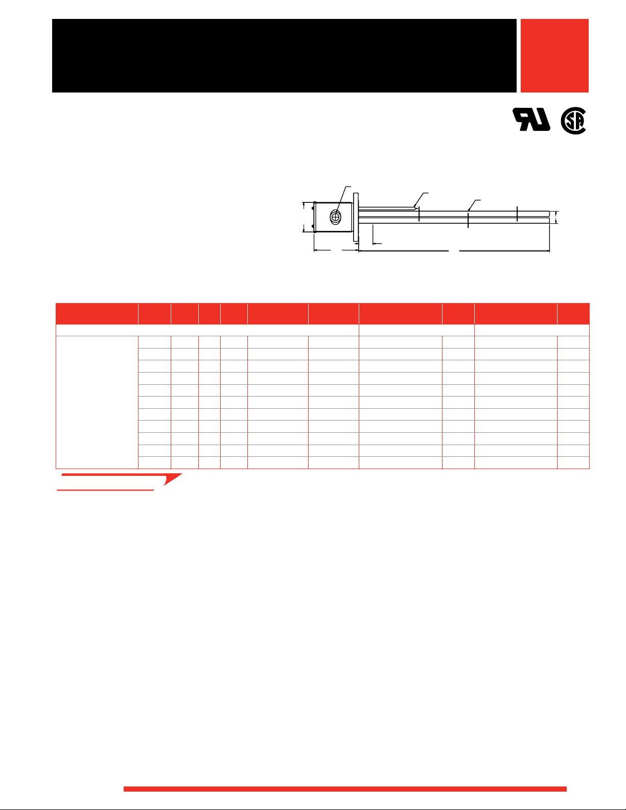
• 8 inch - 150 lb ANSI flange
• WATROD elements
• Without thermostat
• General purpose or
moisture-resistant enclosures
Description Volts kW Ph#Circ.
48 W/in2
Steel Flange
18-Alloy 800
Elements
(7.5 W/cm2)
2
48 W/in
Steel Flange
24-Alloy 800
Elements
(7.5 W/cm2)
• M - Manufacturing lead times
240 50.0 3 3 25
480 50.0 1 3 253/4 (654.0) 121 (55) FRN725N11S M FRN725N11W M
480 50.0 3 2 25
240 75.0 3 6 35
480 75.0 3 2 353/4 (908.0) 130 (59) FRN735N5S M FRN735N5W M
240 100.0 3 6 441/4 (1124.0) 132 (60) FRN744E3S M FRN744E3W M
480 100.0 3 3 441/4 (1124.0) 132 (60) FRN744E5S M FRN744E5W M
240 125.0 3 6
480 125.0 3 6
480 150.0 3 6
480 175.0 3 6 733/16 (1859.0) 151 (69) FRN773D5S M FRN773D5W M
480 200.0 3 6 8211/16
240 67.0 3 4 26
480 67.0 1 3 26
480 67.0 3 2 263/16 (665.2) 129 (59) FRN726D5XS M FRN726D5XW M
240 100.0 3 8 363/16 (919.2) 142 (65) FRN736D3XS M FRN736D3XW M
480 100.0 3 4 363/16 (919.2) 142 (65) FRN736D5XS M FRN736D5XW M
240 133.0 3 8 4411/16
480 133.0 3 4 4411/16
240 167.0 3 8 5411/16
480 167.0 3 8 5411/16
480 200.0 3 8 6311/16
480 233.0 3 8 73
480 267.0 3 8 82
“B” Dim.
in. (mm)
3
/4 (654.0) 121 (55) FRN725N3S M FRN725N3W M
3
/4 (654.0) 121 (55) FRN725N5S M FRN725N5W M
3
/4 (908.0) 130 (59) FRN735N3S M FRN735N3W M
5411/16 (1389.1)
5411/16 (1389.1)
6311/16 (1617.6)
(2100.3) 157 (72) FRN782M5S M FRN782M5W M
3
/16 (665.2) 129 (59) FRN726D3XS M FRN726D3XW M
3
/16 (665.2) 129 (59) FRN726D11XS M FRN726D11XW M
(1135.1) 147 (67) FRN744M3XS M FRN744M3XW M
(1135.1) 147 (67) FRN744M5XS M FRN744M5XW M
(1389.1) 158 (72) FRN754M3XS M FRN754M3XW M
(1389.1) 158 (72) FRN754M5XS M FRN754M5XW M
(1617.6) 166 (76) FRN763M5XS M FRN763M5XW M
3
/16
(1859.0) 175 (80) FRN773D5XS M FRN773D5XW M
11
/16
(2100.3) 184 (84) FRN782M5XS M FRN782M5XW M
General Purpose and
Moisture Resistant
0.475 in. (12.1 mm) Dia. Element
10 in.
(254 mm)
6 in. (152 mm) Cold (Ref.)
3⁄16 in.
8
(208 mm)
“B”
① The number and size of the conduit opening will comply with the
National Electrical Code® standards.
Ship Wt.
lbs (kg)
140 (64) FRN754M3S M FRN754M3W M
140 (64) FRN754M5S M FRN754M5W M
145 (66) FRN763M5S M FRN763M5W M
Notes: • All flange bundles are designed to fit the inside diameter
of the equivalent standard schedule pipe
• For ANSI flange dimensions, reference chart on page 241
Part
Number Del.
General Purpose Enclosure
Truck Shipment only
Part
Number Del.
Moisture-Resistant Enclosure
¾ in. O.D.
7
(197 mm)
261
Page 26

WATLOW
®
Immersion Heaters
6 in. (152 mm) Cold (Ref.)
“B”
13
½ in.
(343 mm)
8
3⁄8 in.
(212.7 mm)
10
3⁄8 in. O.D.
(263.5 mm)
0.475 in. (12.1 mm) Dia. Element
①
6 in. (152 mm) Cold (Ref.)
9
¼ in. O.D.
(235 mm)
8
¼ in.
(210 mm)
“B”
11
5⁄8
in.
(295.3 mm)
0.475 in. (12.1 mm) Dia. Element
①
®
WATROD and FIREBAR ANSI Flange
Immersion Heaters
Application: Process Water
• 10 inch - 150 lb ANSI flange
• WATROD elements
• Without thermostat
• General purpose or
moisture-resistant enclosures
① The number and size of the conduit opening
will comply with the National Electrical Code®
standards.
Description Volts kW Ph#Circ.
48 W/in2
Steel Flange
27-Alloy 800
Elements
(7.5 W/cm
2
)
Application: Process Water
• 12 inch - 150 lb ANSI flange
• WATROD elements
• Without thermostat
• General purpose or
moisture-resistant enclosures
① The number and size of the conduit opening
48 W/in2
Steel Flange
36-Alloy 800
Elements
(7.5 W/cm2)
• M - Manufacturing lead times
will comply with the National Electrical Code®
standards.
Description Volts kW Ph#Circ.
480 190.0 3 9 54
480 262.0 3 9 73
480 250.0 3 6 54
480 350.0 3 12 73
“B” Dim.
in. (mm)
3
/4 (1391) 240 (109) FSN754N5S M FSN754N5W M
1
/4 (1861) 260 (118) FSN773E5S M FSN773E5W M
“B” Dim.
in. (mm)
5
/8 (1387.5) 280 (127) FTN754L5S M FTN754L5W M
1
/8 (1857.4) 291 (132) FTN773C5S M FTN773C5W M
General Purpose
11
5⁄8 in.
(295.3 mm)
(210 mm)
Moisture Resistant
¾ in.
13
(349 mm)
(229 mm)
Ship Wt.
lbs (kg)
General Purpose
13
½ in.
(343 mm)
(212.7 mm)
Moisture Resistant
in.
7⁄8
15
(403.2 mm)
(229 mm)
Ship Wt.
lbs (kg)
①
0.475 in. (12.1 mm) Dia. Element
9
8
¼ in.
6 in. (152 mm) Cold (Ref.)
“B”
①
0.475 in. (12.1 mm) Dia. Element
¼ in. O.D.
9
(235 mm)
6 in. (152 mm) Cold (Ref.)
9 in.
Part
Number Del.
General Purpose Enclosure
“B”
Part
Number
Moisture-Resistant Enclosure
①
0.475 in. (12.1 mm) Dia. Element
10
(263.5 mm)
6 in. (152 mm) Cold (Ref.)
8
9 in.
3⁄8 in.
①
6 in. (152 mm) Cold (Ref.)
Part
Number Del.
General Purpose Enclosure
“B”
0.475 in. (12.1 mm) Dia. Element
“B”
Part
Number
Moisture-Resistant Enclosure
103⁄8 in. O.D.
(263.5 mm)
Notes: • All flange bundles are designed to fit the inside diameter
of the equivalent standard schedule pipe
• For ANSI flange dimensions, reference chart on page 241
Truck Shipment only
¼ in. O.D.
(235 mm)
Del.
3⁄8 in. O.D.
Del.
®
262
Page 27

WATLOW
®
Immersion Heaters
6 in. (152 mm) Cold (Ref.)
“B”
15
1⁄8
in.
(384.2 mm)
12¼ in. O.D.
(311 mm)
8
½ in.
(216 mm)
0.475 in. (12.1 mm) Dia. Element
①
①
®
WATROD and FIREBAR ANSI Flange
Immersion Heaters
Application: Process Water
• 14 inch - 150 lb ANSI flange
• WATROD elements
• Without thermostat
• General purpose or
moisture-resistant enclosures
General Purpose
1⁄8
in.
15
(384.2 mm)
Moisture Resistant
17
¼ in.
(438 mm)
① The number and size of the conduit opening will comply with the
National Electrical Code® standards.
½ in.
8
(216 mm)
91⁄8 in.
(231.8 mm)
①
6 in. (152 mm) Cold (Ref.)
6 in. (152 mm) Cold (Ref.)
0.475 in. (12.1 mm) Dia. Element
“B”
0.475 in. (12.1 mm) Dia. Element
“B”
12¼ in. O.D.
(311 mm)
12¼ in. O.D.
(311 mm)
®
Description Volts kW Ph#Circ.
48 W/in2
Steel Flange
45-Alloy 800
Elements
(7.5 W/cm2)
480 315.0 3 15 54
480 375.0 3 15 63
• M - Manufacturing lead times
“B” Dim.
in. (mm)
1
/2 (1384) 300 (136) FWN754J5S M FWN754J5W M
1
/2 (1613) 310 (141) FWN763J5S M FWN763J5W M
Ship Wt.
lbs (kg)
General Purpose Enclosure
Notes: • All flange bundles are designed to fit the inside diameter
of the equivalent standard schedule pipe
• For ANSI flange dimensions, reference chart on page 241
Truck Shipment only
Part
Number Del.
Part
Number
Moisture-Resistant Enclosure
Del.
263
Page 28

WATLOW
®
Immersion Heaters
2¾ in. O.D.
(70 mm)
¾ in. NPT Knockout
Thermowell
0.475 in. (12.1 mm)
Dia. Element
4 in. (102 mm) Cold (Ref.)
¾
45⁄8 in.
(117.5 mm)
35⁄8 in. Dia.
(92.1 mm)
“B”
®
WATROD and FIREBAR ANSI Flange
Immersion Heaters
Application: Forced Air and
Caustic Solutions
• 3 inch - 150 lb ANSI flange
• WATROD elements
• Without thermostat
• General purpose or
moisture-resistant enclosures
• Single circuit
Description Volts kW Ph
264
2
23 W/in
6
Steel Flange
3-Alloy 800
Elements
(3.6 W/cm2)
• RS - Next day shipment
up to 5 pieces
240 3.0 1 18 (457) 23 (11) FMNA18A10S RS FMNA18A10W RS
240 3.0 3 18 (457) 23 (11) FMNA18A3S RS FMNA18A3W RS
480 3.0 1 18 (457) 23 (11) FMNA18A11S RS FMNA18A11W RS
480 3.0 3 18 (457) 23 (11) FMNA18A5S RS FMNA18A5W RS
240 4.5 1 25
240 4.5 3 25
480 4.5 1 25
480 4.5 3 25
240 6.0 1 33 (838) 28 (13) FMNA33A10S RS FMNA33A10W RS
240 6.0 3 33 (838) 28 (13) FMNA33A3S RS FMNA33A3W RS
480 6.0 1 33 (838) 28 (13) FMNA33A11S RS FMNA33A11W RS
480 6.0 3 33 (838) 28 (13) FMNA33A5S RS FMNA33A5W RS
240 7.5 1 40
240 7.5 3 40
480 7.5 1 40
480 7.5 3 40
240 9.0 1 48 (1219) 32 (15) FMNA48A10S RS FMNA48A10W RS
240 9.0 3 48 (1219) 32 (15) FMNA48A3S RS FMNA48A3W RS
480 9.0 1 48 (1219) 32 (15) FMNA48A11S RS FMNA48A11W RS
480 9.0 3 48 (1219) 32 (15) FMNA48A5S RS FMNA48A5W RS
240 12.5 3 64
480 12.5 1 64
480 12.5 3 64
240 15.0 3 77 (1956) 42 (19) FMNA77A3S RS FMNA77A3W RS
480 15.0 1 77 (1956) 42 (19) FMNA77A11S RS FMNA77A11W RS
480 15.0 3 77 (1956) 42 (19) FMNA77A5S RS FMNA77A5W RS
General Purpose
45⁄8 in.
(117.5 mm)
35⁄8 in. Dia.
(92.1 mm)
¾ in. NPT Knockout
Thermowell
4 in. (102 mm) Cold (Ref.)
“B”
0.475 in. (12.1 mm)
Dia. Element
Moisture Resistant
(2)
53⁄8 in.
(136.5 mm)
1⁄8 in. Dia.
3
(79.4 mm)
in. NPT Hubs
Thermowell
4 in. (102 mm) Cold (Ref.)
“B”
0.475 in. (12.1 mm)
Dia. Element
① The number and size of the conduit opening will comply with the
National Electrical Code® standards.
“B” Dim.
in. (mm)
Ship Wt.
lbs (kg)
Part
Number Del.
Part
Number Del.
General Purpose Enclosure Moisture-Resistant Enclosure
1
⁄2 (648) 27 (13) FMNA25J10S RS FMNA25J10W RS
1
⁄2 (648) 27 (13) FMNA25J3S RS FMNA25J3W RS
1
⁄2 (648) 27 (13) FMNA25J11S RS FMNA25J11W RS
1
⁄2 (648) 27 (13) FMNA25J5S RS FMNA25J5W RS
1
/2 (1029) 30 (14) FMNA40J10S RS FMNA40J10W RS
1
/2 (1029) 30 (14) FMNA40J3S RS FMNA40J3W RS
1
/2 (1029) 30 (14) FMNA40J11S RS FMNA40J11W RS
1
/2 (1029) 30 (14) FMNA40J5S RS FMNA40J5W RS
1
/2 (1638) 37 (17) FMNA64J3S RS FMNA64J3W RS
1
/2 (1638) 37 (17) FMNA64J11S RS FMNA64J11W RS
1
/2 (1638) 37 (17) FMNA64J5S RS FMNA64J5W RS
Notes: • All flange bundles are designed to fit the inside diameter
of the equivalent standard schedule pipe
• For ANSI flange dimensions, reference chart on page 241
6 Can be rewired wye to produce
1
/3 of the original kW and
watt density (3-phase only)
2¾ in. O.D.
(70 mm)
2¾ in. O.D.
(70 mm)
®
Page 29

WATLOW
®
Immersion Heaters
4"-150# FLANGE
®
WATROD and FIREBAR ANSI Flange
Immersion Heaters
Application: Forced Air and
Caustic Solutions
• 4 inch - 150 lb ANSI flange
• WATROD elements
• Without thermostat
• General purpose or
moisture-resistant enclosures
Description Volts kW Ph#Circ.
2
23 W/in
Steel Flange
6-Alloy 800
Elements
(3.6 W/cm2)
• RS - Next day shipment
up to 5 pieces
6
240 6.0 1 1 18 (457) 32 (15) FONA18A10S RS FONA18A10W RS
240 6.0 3 1 18 (457) 32 (15) FONA18A3S RS FONA18A3W RS
480 6.0 1 1 18 (457) 32 (15) FONA18A11S RS FONA18A11W RS
480 6.0 3 1 18 (457) 32 (15) FONA18A5S RS FONA18A5W RS
240 9.0 1 1 25
240 9.0 3 1 25
480 9.0 1 1 25
480 9.0 3 1 25
240 12.0 1 2 33 (838) 39 (18) FONA33A10S RS FONA33A10W RS
240 12.0 3 1 33 (838) 39 (18) FONA33A3S RS FONA33A3W RS
480 12.0 1 1 33 (838) 39 (18) FONA33A11S RS FONA33A11W RS
480 12.0 3 1 33 (838) 39 (18) FONA33A5S RS FONA33A5W RS
240 15.0 1 2 40
240 15.0 3 1 40
480 15.0 1 1 40
480 15.0 3 1 40
240 18.0 1 2 48 (1219) 48 (22) FONA48A10S RS FONA48A10W RS
240 18.0 3 1 48 (1219) 48 (22) FONA48A3S RS FONA48A3W RS
480 18.0 1 1 48 (1219) 48 (22) FONA48A11S RS FONA48A11W RS
480 18.0 3 1 48 (1219) 48 (22) FONA48A5S RS FONA48A5W RS
240 25.0 3 2 64
480 25.0 1 2 64
480 25.0 3 1 64
240 30.0 3 2 77 (1956) 61 (28) FONA77A3S RS FONA77A3W RS
480 30.0 1 2 77 (1956) 61 (28) FONA77A11S RS FONA77A11W RS
480 30.0 3 1 77 (1956) 61 (28) FONA77A5S RS FONA77A5W RS
“B” Dim.
in. (mm)
1
/2 (648) 36 (17) FONA25J10S RS FONA25J10W RS
1
/2 (648) 36 (17) FONA25J3S RS FONA25J3W RS
1
/2 (648) 36 (17) FONA25J11S RS FONA25J11W RS
1
/2 (648) 36 (17) FONA25J5S RS FONA25J5W RS
1
/2 (1029) 43 (20) FONA40J10S RS FONA40J10W RS
1
/2 (1029) 43 (20) FONA40J3S RS FONA40J3W RS
1
/2 (1029) 43 (20) FONA40J11S RS FONA40J11W RS
1
/2 (1029) 43 (20) FONA40J5S RS FONA40J5W RS
1
/2 (1638) 53 (24) FONA64J3S RS FONA64J3W RS
1
/2 (1638) 53 (24) FONA64J11S RS FONA64J11W RS
1
/2 (1638) 53 (24) FONA64J5S RS FONA64J5W RS
General Purpose and
Moisture Resistant
5
½ in.
(140 mm)
(203 mm)
① The number and size of the conduit opening will comply with the
National Electrical Code® standards.
Ship Wt.
lbs (kg)
①
Thermowell
8 in.
4 in. (102 mm) Cold (Ref.)
Part
Number Del.
General Purpose Enclosure Moisture-Resistant Enclosure
Notes: • All flange bundles are designed to fit the inside diameter
of the equivalent standard schedule pipe
• For ANSI flange dimensions, reference chart on page 241
6 Can be rewired wye to produce
watt density (3-phase only)
“B”
1
/3 of the original kW and
0.475 in. (12.1 mm) Dia. Element
3
7⁄8 in. O.D.
(98.4 mm)
Part
Number Del.
®
265
Page 30

WATLOW
®
Immersion Heaters
®
WATROD and FIREBAR ANSI Flange
Immersion Heaters
®
Application: Forced Air and
Caustic Solutions
• 5 inch - 150 lb ANSI flange
• WATROD elements
• Without thermostat
• General purpose or
moisture-resistant enclosures
Description Volts kW Ph#Circ.
23 W/in2 6
Steel Flange
6-Alloy 800
Elements
(3.6 W/cm2)
• RS - Next day shipment
up to 5 pieces
240 6.0 1 1 18 (457) 36 (17) FNNA18A10S RS FNNA18A10W RS
240 6.0 3 1 18 (457) 36 (17) FNNA18A3S RS FNNA18A3W RS
480 6.0 1 1 18 (457) 36 (17) FNNA18A11S RS FNNA18A11W RS
480 6.0 3 1 18 (457) 36 (17) FNNA18A5S RS FNNA18A5W RS
240 9.0 1 1 25
240 9.0 3 1 25
480 9.0 1 1 25
480 9.0 3 1 25
240 12.0 1 2 33 (838) 43 (20) FNNA33A10S RS FNNA33A10W RS
240 12.0 3 1 33 (838) 43 (20) FNNA33A3S RS FNNA33A3W RS
480 12.0 1 1 33 (838) 43 (20) FNNA33A11S RS FNNA33A11W RS
480 12.0 3 1 33 (838) 43 (20) FNNA33A5S RS FNNA33A5W RS
240 15.0 1 2 40
240 15.0 3 1 40
480 15.0 1 1 40
480 15.0 3 1 40
240 18.0 1 2 48 (1219) 52 (24) FNNA48A10S RS FNNA48A10W RS
240 18.0 3 1 48 (1219) 52 (24) FNNA48A3S RS FNNA48A3W RS
480 18.0 1 1 48 (1219) 52 (24) FNNA48A11S RS FNNA48A11W RS
480 18.0 3 1 48 (1219) 52 (24) FNNA48A5S RS FNNA48A5W RS
240 25.0 3 2 64
480 25.0 1 2 64
480 25.0 3 1 64
240 30.0 3 2 77 (1956) 65 (30) FNNA77A3S RS FNNA77A3W RS
480 30.0 1 2 77 (1956) 65 (30) FNNA77A11S RS FNNA77A11W RS
480 30.0 3 1 77 (1956) 65 (30) FNNA77A5S RS FNNA77A5W RS
General Purpose and
Moisture Resistant
7 in.
(178 mm)
8 in. O.D.
(203 mm)
①
4 in. (102 mm) Cold (Ref.)
Thermowell
“B”
0.475 in. (12.1 mm) Dia. Element
① The number and size of the conduit opening will comply with the
National Electrical Code® standards.
“B” Dim.
in. (mm)
1
/2 (648) 40 (19) FNNA25J10S RS FNNA25J10W RS
1
/2 (648) 40 (19) FNNA25J3S RS FNNA25J3W RS
1
/2 (648) 40 (19) FNNA25J11S RS FNNA25J11W RS
1
/2 (648) 40 (19) FNNA25J5S RS FNNA25J5W RS
1
/2 (1029) 47 (22) FNNA40J10S RS FNNA40J10W RS
1
/2 (1029) 47 (22) FNNA40J3S RS FNNA40J3W RS
1
/2 (1029) 47 (22) FNNA40J11S RS FNNA40J11W RS
1
/2 (1029) 47 (22) FNNA40J5S RS FNNA40J5W RS
1
/2 (1638) 57 (26) FNNA64J3S RS FNNA64J3W RS
1
/2 (1638) 57 (26) FNNA64J11S RS FNNA64J11W RS
1
/2 (1638) 57 (26) FNNA64J5S RS FNNA64J5W RS
Ship Wt.
lbs (kg)
Notes: • All flange bundles are designed to fit the inside diameter
of the equivalent standard schedule pipe
• For ANSI flange dimensions, reference chart on page 241
6 Can be rewired wye to produce
watt density (3-phase only)
Part
Number Del.
General Purpose Enclosure
1
/3 of the original kW and
Part
Number Del.
Moisture-Resistant Enclosure
4¾ in. O.D.
(121 mm)
266
Page 31

WATLOW
®
Immersion Heaters
®
WATROD and FIREBAR ANSI Flange
Immersion Heaters
®
Application: Forced Air and
Caustic Solutions
• 5 inch - 150 lb ANSI flange
• WATROD elements
• Without thermostat
• General purpose or
moisture-resistant enclosures
Description Volts kW Ph#Circ.
23 W/in2 6
Steel Flange
9-Alloy 800
Elements
(3.6 W/cm2)
• RS - Next day shipment
up to 5 pieces
• M - Manufacturing lead times
240 9.0 1 1 18 (457) 39 (18) FNNA18A10XS RS FNNA18A10XW RS
240 9.0 3 1 18 (457) 39 (18) FNNA18A3XS RS FNNA18A3XW RS
480 9.0 1 1 18 (457) 39 (18) FNNA18A11XS RS FNNA18A11XW RS
480 9.0 3 1 18 (457) 39 (18) FNNA18A5XS RS FNNA18A5XW RS
240 14.0 1 3 25
240 14.0 3 1 25
480 14.0 1 1 25
480 14.0 3 1 25
240 18.0 1 3 33 (838) 48 (22) FNNA33A10XS RS FNNA33A10XW RS
240 18.0 3 1 33 (838) 48 (22) FNNA33A3XS RS FNNA33A3XW RS
480 18.0 1 1 33 (838) 48 (22) FNNA33A11XS RS FNNA33A11XW RS
480 18.0 3 1 33 (838) 48 (22) FNNA33A5XS RS FNNA33A5XW RS
240 23.0 1 3 40
240 23.0 3 3 40
480 23.0 1 1 40
480 23.0 3 1 40
240 27.0 1 3 48 (1219) 60 (28) FNNA48A10XS RS FNNA48A10XW RS
240 27.0 3 3 48 (1219) 60 (28) FNNA48A3XS RS FNNA48A3XW RS
480 27.0 1 3 48 (1219) 60 (28) FNNA48A11XS RS FNNA48A11XW RS
480 27.0 3 1 48 (1219) 60 (28) FNNA48A5XS RS FNNA48A5XW RS
240 38.0 3 3 64
480 38.0 1 3 64
480 38.0 3 1 64
240 45.0 3 3 77 (1956) 78 (36) FNNA77A3XS M FNNA77A3XW M
480 45.0 1 3 77 (1956) 78 (36) FNNA77A11XS M FNNA77A11XW M
480 45.0 3 3 77 (1956) 78 (36) FNNA77A5XS M FNNA77A5XW M
General Purpose and
Moisture Resistant
7 in.
(178 mm)
8 in. O.D.
(203 mm)
①
4 in. (102 mm) Cold (Ref.)
Thermowell
“B”
0.475 in. (12.1 mm) Dia. Element
① The number and size of the conduit opening will comply with the
National Electrical Code® standards.
“B” Dim.
in. (mm)
1
/2 (648) 45 (21) FNNA25J10XS RS FNNA25J10XW RS
1
/2 (648) 45 (21) FNNA25J3XS RS FNNA25J3XW RS
1
/2 (648) 45 (21) FNNA25J11XS RS FNNA25J11XW RS
1
/2 (648) 45 (21) FNNA25J5XS RS FNNA25J5XW RS
1
/2 (1029) 53 (24) FNNA40J10XS RS FNNA40J10XW RS
1
/2 (1029) 53 (24) FNNA40J3XS RS FNNA40J3XW RS
1
/2 (1029) 53 (24) FNNA40J11XS RS FNNA40J11XW RS
1
/2 (1029) 53 (24) FNNA40J5XS RS FNNA40J5XW RS
1
/2 (1638) 68 (31) FNNA64J3XS RS FNNA64J3XW RS
1
/2 (1638) 68 (31) FNNA64J11XS RS FNNA64J11XW RS
1
/2 (1638) 68 (31) FNNA64J5XS RS FNNA64J5XW RS
Ship Wt.
lbs (kg)
Notes: • All flange bundles are designed to fit the inside diameter
of the equivalent standard schedule pipe
• For ANSI flange dimensions, reference chart on page 241
6 Can be rewired wye to produce
watt density (3-phase only)
Truck Shipment only
Part
Number Del.
General Purpose Enclosure
1
/3 of the original kW and
Part
Number Del.
Moisture-Resistant Enclosure
4¾ in. O.D.
(121 mm)
267
Page 32

WATLOW
®
Immersion Heaters
4¾ in. O.D.
(121 mm)
Thermowell
1 in. (25 mm)
FIREBAR Element
4 in. (102 mm) Cold (Ref.)
“B”
8 in. O.D.
(203 mm)
7 in.
(178 mm)
0.475 in. (12.1 mm) Dia. Element
0.475 in. (12.1 mm) Dia. Element
①
®
WATROD and FIREBAR ANSI Flange
Immersion Heaters
®
Application: Forced Air and
Caustic Solutions
• 6 inch - 150 lb ANSI flange
• WATROD elements
• Without thermostat
• General purpose or
moisture-resistant enclosures
Description Volts kW Ph#Circ.
23 W/in2 6
Steel Flange
12-Alloy 800
Elements
(3.6 W/cm2)
• M - Manufacturing lead times
240 12.0 1 2 17
240 12.0 3 1 17
480 12.0 1 1 17
480 12.0 3 1 17
240 18.0 1 2 25
240 18.0 3 1 25
480 18.0 1 1 25
480 18.0 3 1 25
240 24.0 1 3 32
240 24.0 3 2 32
480 24.0 1 2 32
480 24.0 3 1 32
240 30.0 1 3 40
240 30.0 3 2 40
480 30.0 1 2 40
480 30.0 3 1 40
240 36.0 1 4 47
240 36.0 3 2 47
480 36.0 1 2 47
480 36.0 3 1 47
240 50.0 3 4 64
480 50.0 1 3 64
480 50.0 3 2 64
240 60.0 3 4 76
480 60.0 1 3 76
480 60.0 3 2 76
General Purpose and
Moisture Resistant
8 in.
(203 mm)
8 in.
(203 mm)
① The number and size of the conduit opening will comply with the
National Electrical Code® standards.
“B” Dim.
in. (mm)
7
/8 (454.0) 75 (34) FPNA17R10S M FPNA17R10W M
7
/8 (454.0) 75 (34) FPNA17R3S M FPNA17R3W M
7
/8 (454.0) 75 (34) FPNA17R11S M FPNA17R11W M
7
/8 (454.0) 75 (34) FPNA17R5S M FPNA17R5W M
3
/8 (644.5) 81 (37) FPNA25G10S M FPNA25G10W M
3
/8 (644.5) 81 (37) FPNA25G3S M FPNA25G3W M
3
/8 (644.5) 81 (37) FPNA25G11S M FPNA25G11W M
3
/8 (644.5) 81 (37) FPNA25G5S M FPNA25G5W M
7
/8 (835.0) 85 (39) FPNA32R10S M FPNA32R10W M
7
/8 (835.0) 85 (39) FPNA32R3S M FPNA32R3W M
7
/8 (835.0) 85 (39) FPNA32R11S M FPNA32R11W M
7
/8 (835.0) 85 (39) FPNA32R5S M FPNA32R5W M
3
/8 (1025.5) 92 (42) FPNA40G10S M FPNA40G10W M
3
/8 (1025.5) 92 (42) FPNA40G3S M FPNA40G3W M
3
/8 (1025.5) 92 (42) FPNA40G11S M FPNA40G11W M
3
/8 (1025.5) 92 (42) FPNA40G5S M FPNA40G5W M
7
/8 (1216.0) 100 (46) FPNA47R10S M FPNA47R10W M
7
/8 (1216.0) 100 (46) FPNA47R3S M FPNA47R3W M
7
/8 (1216.0) 100 (46) FPNA47R11S M FPNA47R11W M
7
/8 (1216.0) 100 (46) FPNA47R5S M FPNA47R5W M
3
/8 (1635.1) 110 (50) FPNA64G3S M FPNA64G3W M
3
/8 (1635.1) 110 (50) FPNA64G11S M FPNA64G11W M
3
/8 (1635.1) 110 (50) FPNA64G5S M FPNA64G5W M
7
/8 (1952.4) 118 (54) FPNA76R3S M FPNA76R3W M
7
/8 (1952.4) 118 (54) FPNA76R11S M FPNA76R11W M
7
/8 (1952.4) 118 (54) FPNA76R5S M FPNA76R5W M
Ship Wt.
lbs (kg)
①
Thermowell
7⁄8 in. O.D.
5
(149.2 mm)
4 in. (102 mm) Cold (Ref.)
“B”
Part
Number Del.
General Purpose Enclosure
Moisture-Resistant Enclosure
Part
Number Del.
Notes: • All flange bundles are designed to fit the inside diameter
of the equivalent standard schedule pipe
• For ANSI flange dimensions, reference chart on page 241
6 Can be rewired wye to produce
1
/3 of the original kW and
watt density (3-phase only)
Truck Shipment only
268
Page 33

WATLOW
®
Immersion Heaters
4¾ in. O.D.
(121 mm)
Thermowell
1 in. (25 mm)
FIREBAR Element
4 in. (102 mm) Cold (Ref.)
“B”
8 in. O.D.
(203 mm)
7 in.
(178 mm)
0.475 in. (12.1 mm) Dia. Element
0.475 in. (12.1 mm) Dia. Element
①
®
WATROD and FIREBAR ANSI Flange
Immersion Heaters
Application: Forced Air and
Caustic Solutions
• 6 inch - 150 lb ANSI flange
• WATROD elements
• Without thermostat
• General purpose or
moisture-resistant enclosures
Description Volts kW Ph#Circ.
23 W/in2 6
Steel Flange
15-Alloy 800
Elements
(3.6 W/cm2)
240 15.0 1 3 17
240 15.0 3 1 17
480 15.0 1 1 17
480 15.0 3 1 17
240 23.0 1 3 25
240 23.0 3 5 25
480 23.0 1 1 25
480 23.0 3 1 25
240 30.0 1 3 32
240 30.0 3 5 32
480 30.0 1 3 32
480 30.0 3 1 32
240 38.0 1 5 40
240 38.0 3 5 40
480 38.0 1 3 40
480 38.0 3 1 40
240 45.0 1 5 47
240 45.0 3 5 47
480 45.0 1 3 47
480 45.0 3 5 47
240 63.0 3 5 64
480 63.0 1 3 64
480 63.0 3 5 64
240 75.0 3 5 76
480 75.0 1 5 76
480 75.0 3 5 76
• M - Manufacturing lead times
(203 mm)
“B” Dim.
in. (mm)
7
/8 (454.0) 78 (36) FPNA17R10XS M FPNA17R10XW M
7
/8 (454.0) 78 (36) FPNA17R3XS M FPNA17R3XW M
7
/8 (454.0) 78 (36) FPNA17R11XS M FPNA17R11XW M
7
/8 (454.0) 78 (36) FPNA17R5XS M FPNA17R5XW M
3
/8 (644.5) 85 (39) FPNA25G10XS M FPNA25G10XW M
3
/8 (644.5) 85 (39) FPNA25G3XS M FPNA25G3XW M
3
/8 (644.5) 85 (39) FPNA25G11XS M FPNA25G11XW M
3
/8 (644.5) 85 (39) FPNA25G5XS M FPNA25G5XW M
7
/8 (835.0) 90 (41) FPNA32R10XS M FPNA32R10XW M
7
/8 (835.0) 90 (41) FPNA32R3XS M FPNA32R3XW M
7
/8 (835.0) 90 (41) FPNA32R11XS M FPNA32R11XW M
7
/8 (835.0) 90 (41) FPNA32R5XS M FPNA32R5XW M
3
/8 (1025.5) 98 (45) FPNA40G10XS M FPNA40G10XW M
3
/8 (1025.5) 98 (45) FPNA40G3XS M FPNA40G3XW M
3
/8 (1025.5) 98 (45) FPNA40G11XS M FPNA40G11XW M
3
/8 (1025.5) 98 (45) FPNA40G5XS M FPNA40G5XW M
7
/8 (1216.0) 108 (49) FPNA47R10XS M FPNA47R10XW M
7
/8 (1216.0) 108 (49) FPNA47R3XS M FPNA47R3XW M
7
/8 (1216.0) 108 (49) FPNA47R11XS M FPNA47R11XW M
7
/8 (1216.0) 108 (49) FPNA47R5XS M FPNA47R5XW M
3
/8 (1635.1) 120 (55) FPNA64G3XS M FPNA64G3XW M
3
/8 (1635.1) 120 (55) FPNA64G11XS M FPNA64G11XW M
3
/8 (1635.1) 120 (55) FPNA64G5XS M FPNA64G5XW M
7
/8 (1952.4) 131 (60) FPNA76R3XS M FPNA76R3XW M
7
/8 (1952.4) 131 (60) FPNA76R11XS M FPNA76R11XW M
7
/8 (1952.4) 131 (60) FPNA76R5XS M FPNA76R5XW M
General Purpose and
Moisture Resistant
①
Thermowell
8 in.
4 in. (102 mm) Cold (Ref.)
8 in.
(203 mm)
“B”
① The number and size of the conduit opening will comply with the
National Electrical Code® standards.
Ship Wt.
lbs (kg)
Notes: • All flange bundles are designed to fit the inside diameter
of the equivalent standard schedule pipe
• For ANSI flange dimensions, reference chart on page 241
6 Can be rewired wye to produce
watt density (3-phase only)
Truck Shipment only
Part
Number Del.
General Purpose Enclosure
1
/3 of the original kW and
Part
Number Del.
Moisture-Resistant Enclosure
7⁄8 in. O.D.
5
(149.2 mm)
®
269
Page 34

WATLOW
®
Immersion Heaters
Thermowell
4 in. (102 mm) Cold (Ref.)
“B”
8
3⁄8 in.
(212.7 mm)
8 in.
(203 mm)
1 in. (25 mm) FIREBAR Element
①
①
5
7⁄8
in. O.D.
(149.2 mm)
®
WATROD and FIREBAR ANSI Flange
Immersion Heaters
®
Application: Forced Air and
Caustic Solutions
• 8 inch - 150 lb ANSI flange
• WATROD elements
• Without thermostat
• General purpose or
moisture-resistant enclosures
Description Volts kW Ph#Circ.
23 W/in2 6
Steel Flange
18-Alloy 800
Elements
(3.6 W/cm2)
2
23 W/in
6
Steel Flange
24-Alloy 800
Elements
(3.6 W/cm2)
• M - Manufacturing lead times
240 30.0 1 3 32
240 30.0 3 2 32
480 30.0 1 2 32
480 30.0 3 1 32
240 40.0 3 3 43
480 40.0 1 2 43
480 40.0 3 3 43
240 50.0 3 3 51
480 50.0 1 3 51
480 50.0 3 2 51
240 40.0 1 4 33
240 40.0 3 4 33
480 40.0 1 2 33
480 40.0 3 2 33
240 53.0 3 4 43
480 53.0 1 3 43
480 53.0 3 2 43
240 67.0 3 4 51
480 67.0 1 3 51
480 67.0 3 2 51
General Purpose and
Moisture Resistant
10 in.
(254 mm)
① The number and size of the conduit opening will comply with the
“B” Dim.
in. (mm)
3
/4 (832.0) 130 (59) FRNA32N10S M FRNA32N10W M
3
/4 (832.0) 130 (59) FRNA32N3S M FRNA32N3W M
3
/4 (832.0) 130 (59) FRNA32N11S M FRNA32N11W M
3
/4 (832.0) 130 (59) FRNA32N5S M FRNA32N5W M
1
/4 (1099.0) 132 (60) FRNA43E3S M FRNA43E3W M
1
/4 (1099.0) 132 (60) FRNA43E11S M FRNA43E11W M
1
/4 (1099.0) 132 (60) FRNA43E5S M FRNA43E5W M
11
/16 (1312.9) 137 (63) FRNA51M3S M FRNA51M3W M
11
/16 (1312.9) 137 (63) FRNA51M11S M FRNA51M11W M
11
/16 (1312.9) 137 (63) FRNA51M5S M FRNA51M5W M
3
/16 (843.0) 142 (65) FRNA33D10XS M FRNA33D10XW M
3
/16 (843.0) 142 (65) FRNA33D3XS M FRNA33D3XW M
3
/16 (843.0) 142 (65) FRNA33D11XS M FRNA33D11XW M
3
/16 (843.0) 142 (65) FRNA33D5XS M FRNA33D5XW M
11
/16 (1109.7) 147 (67) FRNA43M3XS M FRNA43M3XW M
11
/16 (1109.7) 147 (67) FRNA43M11XS M FRNA43M11XW M
11
/16 (1109.7) 147 (67) FRNA43M5XS M FRNA43M5XW M
11
11
11
/16 (1312.9) 154 (70) FRNA51M3XS M FRNA51M3XW M
/16 (1312.9) 154 (70) FRNA51M11XS M FRNA51M11XW M
/16 (1312.9) 154 (70) FRNA51M5XS M FRNA51M5XW M
0.475 in. (12.1 mm) Dia. Element
¾ in. O.D.
7
(197 mm)
6 in. (152 mm) Cold (Ref.)
3⁄16 in.
8
(208 mm)
“B”
National Electrical Code® standards.
Ship Wt.
lbs (kg)
Part
Number Del.
General Purpose Enclosure
Part
Number Del.
Moisture-Resistant Enclosure
Notes: • All flange bundles are designed to fit the inside diameter
of the equivalent standard schedule pipe
• For ANSI flange dimensions, reference chart on page 241
6 Can be rewired wye to produce
1
/3 of the original kW and
watt density (3-phase only)
Truck Shipment only
270
Page 35

WATLOW
®
Immersion Heaters
6 in. (152 mm) Cold (Ref.)
9
¼ in. O.D.
(235 mm)
8
¼ in.
(210 mm)
“B”
11
5⁄8 in.
(295.3 mm)
0.475 in. (12.1 mm) Dia. Element
①
®
WATROD and FIREBAR ANSI Flange
Immersion Heaters
®
Application: Forced Air and
Caustic Solutions
• 10 inch - 150 lb ANSI flange
• WATROD elements
• Without thermostat
• General purpose or
moisture-resistant enclosures
Description Volts kW Ph#Circ.
23 W/in2
Steel Flange
27-Alloy 800
Elements
(3.6 W/cm2)
• M - Manufacturing lead times
240 45.0 3 3 33
480 45.0 3 3 33
240 60.0 3 3 43
480 60.0 3 3 43
240 75.0 3 9 51
480 75.0 3 3 51
General Purpose
①
0.475 in. (12.1 mm) Dia. Element
11
5⁄8
in.
(295.3 mm)
8
¼ in.
(210 mm)
6 in. (152 mm) Cold (Ref.)
“B”
Moisture Resistant
①
0.475 in. (12.1 mm) Dia. Element
¾ in.
13
(349 mm)
9 in.
(229 mm)
6 in. (152 mm) Cold (Ref.)
“B”
① The number and size of the conduit opening will comply with the
National Electrical Code® standards.
“B” Dim.
in. (mm)
1
/4 (845) 165 (75) FSNA33E3S M FSNA33E3W M
1
/4 (845) 165 (75) FSNA33E5S M FSNA33E5W M
3
/4 (1111) 195 (89) FSNA43N3S M FSNA43N3W M
3
/4 (1111) 195 (89) FSNA43N5S M FSNA43N5W M
3
/4 (1314) 230 (105) FSNA51N3S M FSNA51N3W M
3
/4 (1314) 230 (105) FSNA51N5S M FSNA51N5W M
Ship Wt.
lbs (kg)
Part
Number Del.
General Purpose Enclosure
Part
Number Del.
Moisture-Resistant Enclosure
Notes: • All flange bundles are designed to fit the inside diameter
of the equivalent standard schedule pipe
• For ANSI flange dimensions, reference chart on page 241
Truck Shipment only
9
¼ in. O.D.
(235 mm)
¼ in. O.D.
9
(235 mm)
271
Page 36

WATLOW
®
Immersion Heaters
6 in. (152 mm) Cold (Ref.)
“B”
13
½ in.
(343 mm)
8
3⁄8 in.
(212.7 mm)
10
3⁄8 in. O.D.
(263.5 mm)
0.475 in. (12.1 mm) Dia. Element
①
®
WATROD and FIREBAR ANSI Flange
Immersion Heaters
®
Application: Forced Air and
Caustic Solutions
• 12 inch - 150 lb ANSI flange
• WATROD elements
• Without thermostat
• General purpose or
moisture-resistant enclosures
Description Volts kW Ph#Circ.
23 W/in2
Steel Flange
36-Alloy 800
Elements
(3.6 W/cm2)
• M - Manufacturing lead times
480 60.0 3 3 33
480 80.0 3 3 43
480 100.0 3 3 51
General Purpose
13
½ in.
(343 mm)
Moisture Resistant
in.
7⁄8
15
(403.2 mm)
① The number and size of the conduit opening will comply with the
National Electrical Code® standards.
“B” Dim.
in. (mm)
1
/8 (841.4) 205 (93)
5
/8 (1108.1) 240 (109)
5
/8 (1311.3) 280 (127)
lbs (kg)
①
0.475 in. (12.1 mm) Dia. Element
6 in. (152 mm) Cold (Ref.)
8
3⁄8 in.
(212.7 mm)
①
6 in. (152 mm) Cold (Ref.)
9 in.
(229 mm)
Ship Wt.
FTNA33C5S
FTNA43L5S
FTNA51L5S
Notes: • All flange bundles are designed to fit the inside diameter
of the equivalent standard schedule pipe
• For ANSI flange dimensions, reference chart on page 241
Part
Number Del.
General Purpose Enclosure
Truck Shipment only
“B”
0.475 in. (12.1 mm) Dia. Element
“B”
Part
Number Del.
Moisture-Resistant Enclosure
M
FTNA33C5W
M
FTNA43L5W
M
FTNA51L5W
10
3⁄8 in. O.D.
(263.5 mm)
103⁄8 in. O.D.
(263.5 mm)
M
M
M
272
Page 37

WATLOW
®
Immersion Heaters
6 in. (152 mm) Cold (Ref.)
“B”
15
1⁄8
in.
(384.2 mm)
12¼ in. O.D.
(311 mm)
8
½ in.
(216 mm)
0.475 in. (12.1 mm) Dia. Element
①
①
®
WATROD and FIREBAR ANSI Flange
Immersion Heaters
Application: Forced Air and
Caustic Solutions
• 14 inch - 150 lb ANSI flange
• WATROD elements
• Without thermostat
• General purpose or
moisture-resistant enclosures
General Purpose
1⁄8
in.
15
(384.2 mm)
Moisture Resistant
17
¼ in.
(438 mm)
① The number and size of the conduit opening will comply with the
National Electrical Code® standards.
½ in.
8
(216 mm)
91⁄8 in.
(231.8 mm)
①
6 in. (152 mm) Cold (Ref.)
6 in. (152 mm) Cold (Ref.)
0.475 in. (12.1 mm) Dia. Element
“B”
0.475 in. (12.1 mm) Dia. Element
“B”
12¼ in. O.D.
(311 mm)
12¼ in. O.D.
(311 mm)
®
Description Volts kW Ph#Circ.
23 W/in2
Steel Flange
45-Alloy 800
Elements
(3.6 W/cm2)
480 75.0 3 3 33 (838) 225 (102) FWNA33A5S M FWNA33A5W M
480 100.0 3 3 43
480 125.0 3 5 51
• M - Manufacturing lead times
“B” Dim.
in. (mm)
1
/2 (1105) 255 (116) FWNA43J5S M FWNA43J5W M
1
/2 (1308) 300 (136) FWNA51J5S M FWNA51J5W M
Ship Wt.
lbs (kg)
General Purpose Enclosure
Notes: • All flange bundles are designed to fit the inside diameter
of the equivalent standard schedule pipe
• For ANSI flange dimensions, reference chart on page 241
Part
Number Del.
Truck Shipment only
Part
Number Del.
Moisture-Resistant Enclosure
273
Page 38

WATLOW
®
Immersion Heaters
2¾ in. O.D.
(70 mm)
¾ in. NPT Knockout
Thermowell
0.475 in. (12.1 mm)
Dia. Element
4 in. (102 mm) Cold (Ref.)
45⁄8 in.
(117.5 mm)
35⁄8 in. Dia.
(92.1 mm)
“B”
®
WATROD and FIREBAR ANSI Flange
Immersion Heaters
Application: Lightweight Oils and
Heat Transfer Oils
• 3 inch - 150 lb ANSI flange
• WATROD elements
• Without thermostat
• General purpose or
moisture-resistant enclosures
• Single circuit
Description Volts kW Ph
23 W/in2
Steel Flange
3-Steel Elements
(3.6 W/cm2)
• RS - Next day shipment
up to 5 pieces
240 3.0 1 18 (457) 23 (11) FMS718A10S RS FMS718A10W RS
240 3.0 3 18 (457) 23 (11) FMS718A3S RS FMS718A3W RS
480 3.0 1 18 (457) 23 (11) FMS718A11S RS FMS718A11W RS
480 3.0 3 18 (457) 23 (11) FMS718A5S RS FMS718A5W RS
240 4.5 1 25
240 4.5 3 25
480 4.5 1 25
480 4.5 3 25
240 6.0 1 33 (838) 28 (13) FMS733A10S RS FMS733A10W RS
240 6.0 3 33 (838) 28 (13) FMS733A3S RS FMS733A3W RS
480 6.0 1 33 (838) 28 (13) FMS733A11S RS FMS733A11W RS
480 6.0 3 33 (838) 28 (13) FMS733A5S RS FMS733A5W RS
240 7.5 1 40
240 7.5 3 40
480 7.5 1 40
480 7.5 3 40
240 9.0 1 48 (1219) 32 (15) FMS748A10S RS FMS748A10W RS
240 9.0 3 48 (1219) 32 (15) FMS748A3S RS FMS748A3W RS
480 9.0 1 48 (1219) 32 (15) FMS748A11S RS FMS748A11W RS
480 9.0 3 48 (1219) 32 (15) FMS748A5S RS FMS748A5W RS
240 12.5 3 64
480 12.5 1 64
480 12.5 3 64
240 15.0 3 77 (1956) 42 (19) FMS777A3S RS FMS777A3W RS
480 15.0 1 77 (1956) 42 (19) FMS777A11S RS FMS777A11W RS
480 15.0 3 77 (1956) 42 (19) FMS777A5S RS FMS777A5W RS
“B” Dim.
in. (mm)
1
/2 (648) 27 (13) FMS725J10S RS FMS725J10W RS
1
/2 (648) 27 (13) FMS725J3S RS FMS725J3W RS
1
/2 (648) 27 (13) FMS725J11S RS FMS725J11W RS
1
/2 (648) 27 (13) FMS725J5S RS FMS725J5W RS
1
/2 (1029) 30 (14) FMS740J10S RS FMS740J10W RS
1
/2 (1029) 30 (14) FMS740J3S RS FMS740J3W RS
1
/2 (1029) 30 (14) FMS740J11S RS FMS740J11W RS
1
/2 (1029) 30 (14) FMS740J5S RS FMS740J5W RS
1
/2 (1638) 37 (17) FMS764J3S RS FMS764J3W RS
1
/2 (1638) 37 (17) FMS764J11S RS FMS764J11W RS
1
/2 (1638) 37 (17) FMS764J5S RS FMS764J5W RS
General Purpose
45⁄8 in.
(117.5 mm)
35⁄8 in. Dia.
(92.1 mm)
Moisture Resistant
53⁄8 in.
(136.5 mm)
1⁄8 in. Dia.
3
(79.4 mm)
Ship Wt.
lbs (kg)
Notes: • All flange bundles are designed to fit the inside diameter
of the equivalent standard schedule pipe
• For ANSI flange dimensions, reference chart on page 241
¾ in. NPT Knockout
Thermowell
4 in. (102 mm) Cold (Ref.)
(2)
¾ in. NPT Hubs
Thermowell
4 in. (102 mm) Cold (Ref.)
Part
Number Del.
General Purpose Enclosure
0.475 in. (12.1 mm)
Dia. Element
“B”
0.475 in. (12.1 mm)
Dia. Element
“B”
Part
Number Del.
Moisture-Resistant Enclosure
2¾ in. O.D.
(70 mm)
2¾ in. O.D.
(70 mm)
®
274
Page 39

WATLOW
®
Immersion Heaters
4"-150# FLANGE
®
WATROD and FIREBAR ANSI Flange
Immersion Heaters
Application: Lightweight Oils and
Heat Transfer Oils
• 4 inch - 150 lb ANSI flange
• WATROD elements
• Without thermostat
• General purpose or
moisture-resistant enclosures
Description Volts kW Ph#Circ.
23 W/in2
Steel Flange
6-Steel Elements
(3.6 W/cm2)
• RS - Next day shipment
up to 5 pieces
240 6.0 1 1 18 (457) 32 (15) FOS718A10S RS FOS718A10W RS
240 6.0 3 1 18 (457) 32 (15) FOS718A3S RS FOS718A3W RS
480 6.0 1 1 18 (457) 32 (15) FOS718A11S RS FOS718A11W RS
480 6.0 3 1 18 (457) 32 (15) FOS718A5S RS FOS718A5W RS
240 9.0 1 1 25
240 9.0 3 1 25
480 9.0 1 1 25
480 9.0 3 1 25
240 12.0 1 2 33 (838) 39 (18) FOS733A10S RS FOS733A10W RS
240 12.0 3 1 33 (838) 39 (18) FOS733A3S RS FOS733A3W RS
480 12.0 1 1 33 (838) 39 (18) FOS733A11S RS FOS733A11W RS
480 12.0 3 1 33 (838) 39 (18) FOS733A5S RS FOS733A5W RS
240 15.0 1 2 40
240 15.0 3 1 40
480 15.0 1 1 40
480 15.0 3 1 40
240 18.0 1 2 48 (1219) 48 (22) FOS748A10S RS FOS748A10W RS
240 18.0 3 1 48 (1219) 48 (22) FOS748A3S RS FOS748A3W RS
480 18.0 1 1 48 (1219) 48 (22) FOS748A11S RS FOS748A11W RS
480 18.0 3 1 48 (1219) 48 (22) FOS748A5S RS FOS748A5W RS
240 25.0 3 2 64
480 25.0 1 2 64
480 25.0 3 1 64
240 30.0 3 2 77 (1956) 61 (28) FOS777A3S RS FOS777A3W RS
480 30.0 1 2 77 (1956) 61 (28) FOS777A11S RS FOS777A11W RS
480 30.0 3 1 77 (1956) 61 (28) FOS777A5S RS FOS777A5W RS
“B” Dim.
in. (mm)
1
/2 (648) 36 (17) FOS725J10S RS FOS725J10W RS
1
/2 (648) 36 (17) FOS725J3S RS FOS725J3W RS
1
/2 (648) 36 (17) FOS725J11S RS FOS725J11W RS
1
/2 (648) 36 (17) FOS725J5S RS FOS725J5W RS
1
/2 (1029) 43 (20) FOS740J10S RS FOS740J10W RS
1
/2 (1029) 43 (20) FOS740J3S RS FOS740J3W RS
1
/2 (1029) 43 (20) FOS740J11S RS FOS740J11W RS
1
/2 (1029) 43 (20) FOS740J5S RS FOS740J5W RS
1
/2 (1638) 53 (24) FOS764J3S RS FOS764J3W RS
1
/2 (1638) 53 (24) FOS764J11S RS FOS764J11W RS
1
/2 (1638) 53 (24) FOS764J5S RS FOS764J5W RS
General Purpose and
Moisture Resistant
5
½
in.
(140 mm)
① The number and size of the conduit opening will comply with the
National Electrical Code® standards.
Ship Wt.
lbs (kg)
①
Thermowell
8 in.
(203 mm)
Notes: • All flange bundles are designed to fit the inside diameter
of the equivalent standard schedule pipe
• For ANSI flange dimensions, reference chart on page 241
4 in. (102 mm) Cold (Ref.)
Part
Number Del.
General Purpose Enclosure
“B”
0.475 in. (12.1 mm) Dia. Element
Part
Number Del.
Moisture-Resistant Enclosure
3
7⁄8 in. O.D.
(98.4 mm)
®
275
Page 40

WATLOW
®
Immersion Heaters
Thermowell
5
½ in.
4 in. (102 mm) Cold (Ref.)
3
7⁄8 in. O.D.
(98.4 mm)
“B”
8 in.
(203 mm)
0.475 in. (12.1 mm) Dia. Element
①
①
®
WATROD and FIREBAR ANSI Flange
Immersion Heaters
®
Application: Lightweight Oils and
Heat Transfer Oils
• 4 inch - 150 lb ANSI flange
• FIREBAR elements
• Without thermostat
• General purpose or
moisture-resistant enclosures
Description Volts kW Ph#Circ.
30 W/in2 3
304 SS Flange
6-Alloy 800
Elements
(4.7 W/cm2)
2
23 W/in
8
304 SS Flange
6-Alloy 800
Elements
(3.6 W/cm2)
• RS - Next day shipment
up to 5 pieces
240 10.0 3 1 16
480 10.0 3 1 16
240 13.0 3 1 19
480 13.0 3 1 19
240 17.0 3 1 24
480 17.0 3 1 24
240 21.0 3 2 30 (762) 44 (20) FONF30A12S RS FONF30A12W RS
480 21.0 3 1 30 (762) 44 (20) FONF30A13S RS FONF30A13W RS
240 25.5 3 2 35 (889) 46 (21) FONF35A12S RS FONF35A12W RS
480 25.5 3 1 35 (889) 46 (21) FONF35A13S RS FONF35A13W RS
240 34.0 3 2 45
480 34.0 3 1 45
480 43.0 3 2 56 (1422) 54 (25) FONF56A13S RS FONF56A13W RS
240 7.5 3 1 16
240 10.0 3 1 19
240 12.8 3 1 24
480 12.8 3 1 24
240 15.8 3 1 30 (762) 44 (20) FONF30A20S RS FONF30A20W RS
480 15.8 3 1 30 (762) 44 (20) FONF30A19S RS FONF30A19W RS
240 19.0 3 1 35 (889) 46 (21) FONF35A20S RS FONF35A20W RS
480 19.0 3 1 35 (889) 46 (21) FONF35A19S RS FONF35A19W RS
240 25.0 3 2 45
480 25.0 3 1 45
240 32.3 3 2 56 (1422) 54 (25) FONF56A20S RS FONF56A20W RS
480 32.3 3 1 56 (1422) 54 (25) FONF56A19S RS FONF56A19W RS
General Purpose and
Moisture Resistant
5½ in.
(140 mm)
83⁄8 in.
(212.7 mm)
Thermowell
4 in. (102 mm) Cold (Ref.)
“B”
1 in. (25 mm)
FIREBAR Element
① The number and size of the conduit opening will comply with the
National Electrical Code® standards.
“B” Dim.
in. (mm)
1
/2 (420) 35 (16) FONF16J12S RS FONF16J12W RS
1
/2 (420) 35 (16) FONF16J13S RS FONF16J13W RS
1
/2 (495) 38 (17) FONF19J12S RS FONF19J12W RS
1
/2 (495) 38 (17) FONF19J13S RS FONF19J13W RS
1
/2 (622) 41 (19) FONF24J12S RS FONF24J12W RS
1
/2 (622) 41 (19) FONF24J13S RS FONF24J13W RS
1
/2 (1156) 50 (23) FONF45J12S RS FONF45J12W RS
1
/2 (1156) 50 (23) FONF45J13S RS FONF45J13W RS
1
/2 (420) 35 (16) FONF16J20S RS FONF16J20W RS
1
/2 (495) 38 (17) FONF19J20S RS FONF19J20W RS
1
/2 (622) 41 (19) FONF24J20S RS FONF24J20W RS
1
/2 (622) 41 (19) FONF24J19S RS FONF24J19W RS
1
/2 (1156) 50 (23) FONF45J20S RS FONF45J20W RS
1
/2 (1156) 50 (23) FONF45J19S RS FONF45J19W RS
Ship Wt.
lbs (kg)
Part
Number Del.
General Purpose Enclosure
Part
Number Del.
Moisture-Resistant Enclosure
Notes: • All flange bundles are designed to fit the inside diameter
of the equivalent standard schedule pipe
• For ANSI flange dimensions, reference chart on page 241
3 Wired for 3-phase operation only
8 Can be rewired for 1-phase
37⁄8 in. O.D.
(98.4 mm)
276
Page 41

WATLOW
®
Immersion Heaters
®
WATROD and FIREBAR ANSI Flange
Immersion Heaters
Application: Lightweight Oils and
Heat Transfer Oils
• 5 inch - 150 lb ANSI flange
• WATROD elements
• Without thermostat
• General purpose or
moisture-resistant enclosures
Description Volts kW Ph#Circ.
23 W/in2
Steel Flange
6-Steel Elements
(3.6 W/cm2)
• RS - Next day shipment
up to 5 pieces
240 6.0 1 1 18 (457) 36 (17) FNS718A10S RS FNS718A10W RS
240 6.0 3 1 18 (457) 36 (17) FNS718A3S RS FNS718A3W RS
480 6.0 1 1 18 (457) 36 (17) FNS718A11S RS FNS718A11W RS
480 6.0 3 1 18 (457) 36 (17) FNS718A5S RS FNS718A5W RS
240 9.0 1 1 25
240 9.0 3 1 25
480 9.0 1 1 25
480 9.0 3 1 25
240 12.0 1 2 33 (838) 43 (20) FNS733A10S RS FNS733A10W RS
240 12.0 3 1 33 (838) 43 (20) FNS733A3S RS FNS733A3W RS
480 12.0 1 1 33 (838) 43 (20) FNS733A11S RS FNS733A11W RS
480 12.0 3 1 33 (838) 43 (20) FNS733A5S RS FNS733A5W RS
240 15.0 1 2 40
240 15.0 3 1 40
480 15.0 1 1 40
480 15.0 3 1 40
240 18.0 1 2 48 (1219) 52 (24) FNS748A10S RS FNS748A10W RS
240 18.0 3 1 48 (1219) 52 (24) FNS748A3S RS FNS748A3W RS
480 18.0 1 1 48 (1219) 52 (24) FNS748A11S RS FNS748A11W RS
480 18.0 3 1 48 (1219) 52 (24) FNS748A5S RS FNS748A5W RS
240 25.0 3 2 64
480 25.0 1 2 64
480 25.0 3 1 64
240 30.0 3 2 77 (1956) 65 (30) FNS777A3S RS FNS777A3W RS
480 30.0 1 2 77 (1956) 65 (30) FNS777A11S RS FNS777A11W RS
480 30.0 3 1 77 (1956) 65 (30) FNS777A5S RS FNS777A5W RS
“B” Dim.
in. (mm)
1
/2 (648) 40 (19) FNS725J10S RS FNS725J10W RS
1
/2 (648) 40 (19) FNS725J3S RS FNS725J3W RS
1
/2 (648) 40 (19) FNS725J11S RS FNS725J11W RS
1
/2 (648) 40 (19) FNS725J5S RS FNS725J5W RS
1
/2 (1029) 47 (22) FNS740J10S RS FNS740J10W RS
1
/2 (1029) 47 (22) FNS740J3S RS FNS740J3W RS
1
/2 (1029) 47 (22) FNS740J11S RS FNS740J11W RS
1
/2 (1029) 47 (22) FNS740J5S RS FNS740J5W RS
1
/2 (1638) 57 (26) FNS764J3S RS FNS764J3W RS
1
/2 (1638) 57 (26) FNS764J11S RS FNS764J11W RS
1
/2 (1638) 57 (26) FNS764J5S RS FNS764J5W RS
General Purpose and
Moisture Resistant
7 in.
(178 mm)
8 in. O.D.
(203 mm)
① The number and size of the conduit opening will comply with the
National Electrical Code® standards.
Ship Wt.
lbs (kg)
①
4 in. (102 mm) Cold (Ref.)
Number Del.
General Purpose Enclosure
Notes: • All flange bundles are designed to fit the inside diameter
of the equivalent standard schedule pipe
• For ANSI flange dimensions, reference chart on page 241
Part
Thermowell
“B”
0.475 in. (12.1 mm) Dia. Element
4¾ in. O.D.
(121 mm)
Part
Number Del.
Moisture-Resistant Enclosure
®
277
Page 42

WATLOW
®
Immersion Heaters
®
WATROD and FIREBAR ANSI Flange
Immersion Heaters
®
Application: Lightweight Oils and
Heat Transfer Oils
• 5 inch - 150 lb ANSI flange
• WATROD elements
• Without thermostat
• General purpose or
moisture-resistant enclosures
Description Volts kW Ph#Circ.
23 W/in2
Steel Flange
9-Steel Elements
(3.6 W/cm2)
• RS - Next day shipment
up to 5 pieces
• M - Manufacturing lead times
240 9.0 1 1 18 (457) 39 (18) FNS718A10XS RS FNS718A10XW RS
240 9.0 3 1 18 (457) 39 (18) FNS718A3XS RS FNS718A3XW RS
480 9.0 1 1 18 (457) 39 (18) FNS718A11XS RS FNS718A11XW RS
480 9.0 3 1 18 (457) 39 (18) FNS718A5XS RS FNS718A5XW RS
240 14.0 1 3 25
240 14.0 3 1 25
480 14.0 1 1 25
480 14.0 3 1 25
240 18.0 1 3 33 (838) 48 (22) FNS733A10XS RS FNS733A10XW RS
240 18.0 3 1 33 (838) 48 (22) FNS733A3XS RS FNS733A3XW RS
480 18.0 1 1 33 (838) 48 (22) FNS733A11XS RS FNS733A11XW RS
480 18.0 3 1 33 (838) 48 (22) FNS733A5XS RS FNS733A5XW RS
240 23.0 1 3 40
240 23.0 3 3 40
480 23.0 1 1 40
480 23.0 3 1 40
240 27.0 1 3 48 (1219) 60 (28) FNS748A10XS RS FNS748A10XW RS
240 27.0 3 3 48 (1219) 60 (28) FNS748A3XS RS FNS748A3XW RS
480 27.0 1 3 48 (1219) 60 (28) FNS748A11XS RS FNS748A11XW RS
480 27.0 3 1 48 (1219) 60 (28) FNS748A5XS RS FNS748A5XW RS
240 38.0 3 3 64
480 38.0 1 3 64
480 38.0 3 1 64
240 45.0 3 3 77 (1956) 78 (36) FNS777A3XS M FNS777A3XW M
480 45.0 1 3 77 (1956) 78 (36) FNS777A11XS M FNS777A11XW M
480 45.0 3 3 77 (1956) 78 (36) FNS777A5XS M FNS777A5XW M
General Purpose and
Moisture Resistant
7 in.
(178 mm)
8 in. O.D.
(203 mm)
①
4 in. (102 mm) Cold (Ref.)
Thermowell
“B”
0.475 in. (12.1 mm) Dia. Element
① The number and size of the conduit opening will comply with the
National Electrical Code® standards.
“B” Dim.
in. (mm)
1
/2 (648) 45 (21) FNS725J10XS RS FNS725J10XW RS
1
/2 (648) 45 (21) FNS725J3XS RS FNS725J3XW RS
1
/2 (648) 45 (21) FNS725J11XS RS FNS725J11XW RS
1
/2 (648) 45 (21) FNS725J5XS RS FNS725J5XW RS
1
/2 (1029) 53 (24) FNS740J10XS RS FNS740J10XW RS
1
/2 (1029) 53 (24) FNS740J3XS RS FNS740J3XW RS
1
/2 (1029) 53 (24) FNS740J11XS RS FNS740J11XW RS
1
/2 (1029) 53 (24) FNS740J5XS RS FNS740J5XW RS
1
/2 (1638) 68 (31) FNS764J3XS RS FNS764J3XW RS
1
/2 (1638) 68 (31) FNS764J11XS RS FNS764J11XW RS
1
/2 (1638) 68 (31) FNS764J5XS RS FNS764J5XW RS
Ship Wt.
lbs (kg)
Notes: • All flange bundles are designed to fit the inside diameter
of the equivalent standard schedule pipe
• For ANSI flange dimensions, reference chart on page 241
Part
Number Del.
General Purpose Enclosure
Truck Shipment only
Part
Number Del.
Moisture-Resistant Enclosure
4¾ in. O.D.
(121 mm)
278
Page 43

WATLOW
®
Immersion Heaters
4¾ in. O.D.
(121 mm)
Thermowell
1 in. (25 mm)
FIREBAR Element
4 in. (102 mm) Cold (Ref.)
“B”
8 in. O.D.
(203 mm)
7 in.
(178 mm)
0.475 in. (12.1 mm) Dia. Element
①
®
WATROD and FIREBAR ANSI Flange
Immersion Heaters
Application: Lightweight Oils and
Heat Transfer Oils
• 6 inch - 150 lb ANSI flange
• WATROD elements
• Without thermostat
• General purpose or
moisture-resistant enclosures
Description Volts kW Ph#Circ.
23 W/in2
Steel Flange
12-Steel Elements
(3.6 W/cm2)
• M - Manufacturing lead times
240 12.0 1 2 17
240 12.0 3 1 17
480 12.0 1 1 17
480 12.0 3 1 17
240 18.0 1 2 25
240 18.0 3 1 25
480 18.0 1 1 25
480 18.0 3 1 25
240 24.0 1 3 32
240 24.0 3 2 32
480 24.0 1 2 32
480 24.0 3 1 32
240 30.0 1 3 40
240 30.0 3 2 40
480 30.0 1 2 40
480 30.0 3 1 40
240 36.0 1 4 47
240 36.0 3 2 47
480 36.0 1 2 47
480 36.0 3 1 47
240 50.0 3 4 64
480 50.0 1 3 64
480 50.0 3 2 64
240 60.0 3 4 76
480 60.0 1 3 76
480 60.0 3 2 76
“B” Dim.
in. (mm)
7
/8 (454.0) 75 (34) FPS717R10S M FPS717R10W M
7
/8 (454.0) 75 (34) FPS717R3S M FPS717R3W M
7
/8 (454.0) 75 (34) FPS717R11S M FPS717R11W M
7
/8 (454.0) 75 (34) FPS717R5S M FPS717R5W M
3
/8 (644.5) 81 (37) FPS725G10S M FPS725G10W M
3
/8 (644.5) 81 (37) FPS725G3S M FPS725G3W M
3
/8 (644.5) 81 (37) FPS725G11S M FPS725G11W M
3
/8 (644.5) 81 (37) FPS725G5S M FPS725G5W M
7
/8 (835.0) 85 (39) FPS732R10S M FPS732R10W M
7
/8 (835.0) 85 (39) FPS732R3S M FPS732R3W M
7
/8 (835.0) 85 (39) FPS732R11S M FPS732R11W M
7
/8 (835.0) 85 (39) FPS732R5S M FPS732R5W M
3
/8 (1025.5) 92 (42) FPS740G10S M FPS740G10W M
3
/8 (1025.5) 92 (42) FPS740G3S M FPS740G3W M
3
/8 (1025.5) 92 (42) FPS740G11S M FPS740G11W M
3
/8 (1025.5) 92 (42) FPS740G5S M FPS740G5W M
7
/8 (1216.0) 100 (46) FPS747R10S M FPS747R10W M
7
/8 (1216.0) 100 (46) FPS747R3S M FPS747R3W M
7
/8 (1216.0) 100 (46) FPS747R11S M FPS747R11W M
7
/8 (1216.0) 100 (46) FPS747R5S M FPS747R5W M
3
/8 (1635.1) 110 (50) FPS764G3S M FPS764G3W M
3
/8 (1635.1) 110 (50) FPS764G11S M FPS764G11W M
3
/8 (1635.1) 110 (50) FPS764G5S M FPS764G5W M
7
/8 (1952.4) 118 (54) FPS776R3S M FPS776R3W M
7
/8 (1952.4) 118 (54) FPS776R11S M FPS776R11W M
7
/8 (1952.4) 118 (54) FPS776R5S M FPS776R5W M
General Purpose and
Moisture Resistant
8 in.
(203 mm)
(203 mm)
① The number and size of the conduit opening will comply with the
National Electrical Code® standards.
Ship Wt.
lbs (kg)
8 in.
①
Thermowell
4 in. (102 mm) Cold (Ref.)
“B”
Part
Number Del.
General Purpose Enclosure
0.475 in. (12.1 mm) Dia. Element
Part
Number Del.
Moisture-Resistant Enclosure
Notes: • All flange bundles are designed to fit the inside diameter
of the equivalent standard schedule pipe
• For ANSI flange dimensions, reference chart on page 241
Truck Shipment only
7⁄8 in. O.D.
5
(149.2 mm)
®
279
Page 44

WATLOW
®
Immersion Heaters
4¾ in. O.D.
(121 mm)
Thermowell
1 in. (25 mm)
FIREBAR Element
4 in. (102 mm) Cold (Ref.)
“B”
8 in. O.D.
(203 mm)
7 in.
(178 mm)
0.475 in. (12.1 mm) Dia. Element
①
®
WATROD and FIREBAR ANSI Flange
Immersion Heaters
®
Application: Lightweight Oils and
Heat Transfer Oils
• 6 inch - 150 lb ANSI flange
• WATROD elements
• Without thermostat
• General purpose or
moisture-resistant enclosures
Description Volts kW Ph#Circ.
23 W/in2
Steel Flange
15-Steel Elements
(3.6 W/cm2)
• M - Manufacturing lead times
240 15.0 1 3 17
240 15.0 3 1 17
480 15.0 1 1 17
480 15.0 3 1 177/8 (454.0) 78 (36) FPS717R5XS M FPS717R5XW M
240 23.0 1 3 25
240 23.0 3 5 25
480 23.0 1 1 25
480 23.0 3 1 25
240 30.0 1 3 327/8 (835.0) 90 (41) FPS732R10XS M FPS732R10XW M
240 30.0 3 5 32
480 30.0 1 3 32
480 30.0 3 1 32
240 38.0 1 5 40
240 38.0 3 5 403/8 (1025.5) 98 (45) FPS740G3XS M FPS740G3XW M
480 38.0 1 3 40
480 38.0 3 1 40
240 45.0 1 5 47
240 45.0 3 5 477/8 (1216.0) 108 (49) FPS747R3XS M FPS747R3XW M
480 45.0 1 3 47
480 45.0 3 5 47
240 63.0 3 5 64
480 63.0 1 3 64
480 63.0 3 5 64
240 75.0 3 5 767/8 (1952.4) 131 (60) FPS776R3XS M FPS776R3XW M
480 75.0 1 5 76
480 75.0 3 5 76
General Purpose and
Moisture Resistant
8 in.
(203 mm)
8 in.
(203 mm)
①
Thermowell
4 in. (102 mm) Cold (Ref.)
“B”
0.475 in. (12.1 mm) Dia. Element
① The number and size of the conduit opening will comply with the
National Electrical Code® standards.
“B” Dim.
in. (mm)
7
/8 (454.0) 78 (36) FPS717R10XS M FPS717R10XW M
7
/8 (454.0) 78 (36) FPS717R3XS M FPS717R3XW M
7
/8 (454.0) 78 (36) FPS717R11XS M FPS717R11XW M
3
/8 (644.5) 85 (39) FPS725G10XS M FPS725G10XW M
3
/8 (644.5) 85 (39) FPS725G3XS M FPS725G3XW M
3
/8 (644.5) 85 (39) FPS725G11XS M FPS725G11XW M
3
/8 (644.5) 85 (39) FPS725G5XS M FPS725G5XW M
7
/8 (835.0) 90 (41) FPS732R3XS M FPS732R3XW M
7
/8 (835.0) 90 (41) FPS732R11XS M FPS732R11XW M
7
/8 (835.0) 90 (41) FPS732R5XS M FPS732R5XW M
3
/8 (1025.5) 98 (45) FPS740G10XS M FPS740G10XW M
3
/8 (1025.5) 98 (45) FPS740G11XS M FPS740G11XW M
3
/8 (1025.5) 98 (45) FPS740G5XS M FPS740G5XW M
7
/8 (1216.0) 108 (49) FPS747R10XS M FPS747R10XW M
7
/8 (1216.0) 108 (49) FPS747R11XS M FPS747R11XW M
7
/8 (1216.0) 108 (49) FPS747R5XS M FPS747R5XW M
3
/8 (1635.1) 120 (55) FPS764G3XS M FPS764G3XW M
3
/8 (1635.1) 120 (55) FPS764G11XS M FPS764G11XW M
3
/8 (1635.1) 120 (55) FPS764G5XS M FPS764G5XW M
7
/8 (1952.4) 131 (60) FPS776R11XS M FPS776R11XW M
7
/8 (1952.4) 131 (60) FPS776R5XS M FPS776R5XW M
Ship Wt.
lbs (kg)
Part
Number Del.
General Purpose Enclosure
Part
Number Del.
Moisture-Resistant Enclosure
Notes: • All flange bundles are designed to fit the inside diameter
of the equivalent standard schedule pipe
• For ANSI flange dimensions, reference chart on page 241
Truck Shipment only
7⁄8 in. O.D.
5
(149.2 mm)
280
Page 45

WATLOW
®
Immersion Heaters
®
WATROD and FIREBAR ANSI Flange
Immersion Heaters
®
Application: Lightweight Oils and
Heat Transfer Oils
• 6 inch - 150 lb ANSI flange
• FIREBAR elements
• Without thermostat
• General purpose or
moisture-resistant enclosures
Description Volts kW Ph#Circ.
30 W/in2 3
304 SS Flange
15-Alloy 800
Elements
(4.7 W/cm2)
2
23 W/in
304 SS Flange
15-Alloy 800
Elements
(3.6 W/cm2)
• M - Manufacturing lead times
240 25.0 3 5 16
480 25.0 3 5 16
240 32.0 3 5 19
480 32.0 3 5 19
240 42.0 3 5 24
480 42.0 3 5 24
240 52.0 3 5 30 (762) 91 (42) FPNF30A12S M FPNF30A12W M
480 52.0 3 5 30 (762) 91 (42) FPNF30A13S M FPNF30A13W M
240 64.0 3 5 35 (889) 95 (43) FPNF35A12S M FPNF35A12W M
480 64.0 3 5 35 (889) 95 (43) FPNF35A13S M FPNF35A13W M
240 85.0 3 5 45
480 85.0 3 5 45
480 110.0 3 5 56 (1422) 116 (53) FPNF56A13S M FPNF56A13W M
240 19.0 3 5 16
240 24.0 3 5 19
240 32.0 3 5 24
480 32.0 3 5 24
240 40.0 3 5 30 (762) 91 (42) FPNF30A20S M FPNF30A20W M
480 40.0 3 5 30 (762) 91 (42) FPNF30A19S M FPNF30A19W M
240 48.0 3 5 35 (889) 95 (43) FPNF35A20S M FPNF35A20W M
480 48.0 3 5 35 (889) 95 (43) FPNF35A19S M FPNF35A19W M
240 64.0 3 5 45
480 64.0 3 5 45
240 80.0 3 5 56 (1422) 116 (53) FPNF56A20S M FPNF56A20W M
480 80.0 3 5 56 (1422) 116 (53) FPNF56A19S M FPNF56A19W M
General Purpose and
Moisture Resistant
8 in.
(203 mm)
3⁄8
in.
8
(212.7 mm)
①
4 in. (102 mm) Cold (Ref.)
Thermowell
“B”
1 in. (25 mm) FIREBAR Element
① The number and size of the conduit opening will comply with the
National Electrical Code® standards.
“B” Dim.
in. (mm)
1
/2 (419) 81 (37) FPNF16J12S M FPNF16J12W M
1
/2 (419) 81 (37) FPNF16J13S M FPNF16J13W M
1
/2 (495) 84 (38) FPNF19J12S M FPNF19J12W M
1
/2 (495) 84 (38) FPNF19J13S M FPNF19J13W M
1
/2 (622) 87 (40) FPNF24J12S M FPNF24J12W M
1
/2 (622) 87 (40) FPNF24J13S M FPNF24J13W M
1
/2 (1156) 106 (48) FPNF45J12S M FPNF45J12W M
1
/2 (1156) 106 (48) FPNF45J13S M FPNF45J13W M
1
/2 (419) 81 (37) FPNF16J20S M FPNF16J20W M
1
/2 (495) 84 (38) FPNF19J20S M FPNF19J20W M
1
/2 (622) 87 (40) FPNF24J20S M FPNF24J20W M
1
/2 (622) 87 (40) FPNF24J19S M FPNF24J19W M
1
/2 (1156) 106 (48) FPNF45J20S M FPNF45J20W M
1
/2 (1156) 106 (48) FPNF45J19S M FPNF45J19W M
Ship Wt.
lbs (kg)
Notes: • All flange bundles are designed to fit the inside diameter
of the equivalent standard schedule pipe
• For ANSI flange dimensions, reference chart on page 241
3 Wired for 3-phase operation only
Truck Shipment only
Part
Number Del.
General Purpose Enclosure
Part
Number Del.
Moisture-Resistant Enclosure
57⁄8 in. O.D.
(149.2 mm)
281
Page 46

WATLOW
®
Immersion Heaters
Thermowell
4 in. (102 mm) Cold (Ref.)
“B”
8
3⁄8 in.
(212.7 mm)
8 in.
(203 mm)
1 in. (25 mm) FIREBAR Element
①
57⁄8 in. O.D.
(149.2 mm)
®
WATROD and FIREBAR ANSI Flange
Immersion Heaters
®
Application: Lightweight Oils and
Heat Transfer Oils
• 8 inch - 150 lb ANSI flange
• WATROD elements
• Without thermostat
• General purpose or
moisture-resistant enclosures
① The number and size of the conduit open-
ing will comply with the National Electrical
Code® standards.
Description Volts kW Ph#Circ.
23 W/in2
Steel Flange
18-Steel Elements
(3.6 W/cm2)
2
23 W/in
Steel Flange
24-Steel Elements
(3.6 W/cm2)
• M - Manufacturing lead times
282
240 30.0 1 3 32
240 30.0 3 2 323/4 (832.0) 130 (59)
480 30.0 1 2 323/4 (832.0) 130 (59)
480 30.0 3 1 323/4 (832.0) 130 (59)
240 40.0 3 3 431/4 (1099.0) 132 (60)
480 40.0 1 2 431/4 (1099.0) 132 (60)
480 40.0 3 2 431/4 (1099.0) 132 (60)
240 50.0 3 3 5111/16 (1312.9) 137 (63)
480 50.0 1 3 5111/16 (1312.9) 137 (63)
480 50.0 3 2 5111/16 (1312.9) 137 (63)
240 60.0 3 6 623/16 (1579.6) 154 (70)
480 60.0 1 3 623/16 (1579.6) 154 (70)
480 60.0 3 2 623/16 (1579.6) 154 (70)
240 70.0 3 6 7011/16 (1795.5) 160 (73)
480 70.0 1 6 7011/16 (1795.5) 160 (73)
480 70.0 3 2 7011/16 (1795.5) 160 (73)
240 80.0 3 6 7911/16 (2024.1) 172 (78)
480 80.0 3 3 7911/16 (2024.1) 172 (78)
240 40.0 1 4 33
240 40.0 3 4 333/16 (843.0) 142 (65)
480 40.0 1 2 333/16 (843.0) 142 (65)
480 40.0 3 2 333/16 (843.0) 142 (65)
240 53.0 3 4 4311/16 (1109.7) 147 (67)
480 53.0 1 3 4311/16 (1109.7) 147 (67)
480 53.0 3 2 4311/16 (1109.7) 147 (67)
240 67.0 3 4 5111/16 (1312.9) 154 (70)
480 67.0 1 3 5111/16 (1312.9) 154 (70)
480 67.0 3 2 5111/16 (1312.9) 154 (70)
240 80.0 3 8 623/16 (1579.6) 166 (76)
480 80.0 1 4 623/16 (1579.6) 166 (76)
480 80.0 3 4 623/16 (1579.6) 166 (76)
240 93.0 3 8 7011/16 (1795.5) 175 (80)
480 93.0 1 6 7011/16 (1795.5) 175 (80)
480 93.0 3 4 7011/16 (1795.5) 175 (80)
240 107.0 3 8 7911/16 (2024.1) 181 (82)
480 107.0 3 4 7911/16 (2024.1) 181 (82)
Truck Shipment only
General Purpose and
Moisture Resistant
10 in.
(254 mm)
“B” Dim.
in. (mm)
3
/4 (832.0) 130 (59)
3
/16 (843.0) 142 (65)
lbs (kg)
①
6 in. (152 mm) Cold (Ref.)
3⁄16 in.
8
(208 mm)
Ship Wt.
Notes: • All flange bundles are designed to fit the inside diameter
of the equivalent standard schedule pipe
• For ANSI flange dimensions, reference chart on page 241
Part
Number Del.
General Purpose Enclosure
FRS732N10S
FRS732N3S
FRS732N11S
FRS732N5S
FRS743E3S
FRS743E11S
FRS743E5S
FRS751M3S
FRS751M11S
FRS751M5S
FRS762D3S
FRS762D11S
FRS762D5S
FRS770M3S
FRS770M11S
FRS770M5S
FRS779M3S
FRS779M5S
FRS733D10XS
FRS733D3XS
FRS733D11XS
FRS733D5XS
FRS743M3XS
FRS743M11XS
FRS743M5XS
FRS751M3XS
FRS751M11XS
FRS751M5XS
FRS762D3XS
FRS762D11XS
FRS762D5XS
FRS770M3XS
FRS770M11XS
FRS770M5XS
FRS779M3XS
FRS779M5XS
“B”
M
M
M
M
M
M
M
M
M
M
M
M
M
M
M
M
M
M
M
M
M
M
M
M
M
M
M
M
M
M
M
M
M
M
M
M
0.475 in. (12.1 mm) Dia. Element
7
Part
Number Del.
Moisture-Resistant Enclosure
FRS732N10W
FRS732N3W
FRS732N11W
FRS732N5W
FRS743E3W
FRS743E11W
FRS743E5W
FRS751M3W
FRS751M11W
FRS751M5W
FRS762D3W
FRS762D11W
FRS762D5W
FRS770M3W
FRS770M11W
FRS770M5W
FRS779M3W
FRS779M5W
FRS733D10XW
FRS733D3XW
FRS733D11XW
FRS733D5XW
FRS743M3XW
FRS743M11XW
FRS743M5XW
FRS751M3XW
FRS751M11XW
FRS751M5XW
FRS762D3XW
FRS762D11XW
FRS762D5XW
FRS770M3XW
FRS770M11XW
FRS770M5XW
FRS779M3XW
FRS779M5XW
¾ in. O.D.
(197 mm)
M
M
M
M
M
M
M
M
M
M
M
M
M
M
M
M
M
M
M
M
M
M
M
M
M
M
M
M
M
M
M
M
M
M
M
M
Page 47

WATLOW
®
Immersion Heaters
6 in. (152 mm) Cold (Ref.)
9
¼ in. O.D.
(235 mm)
8
¼ in.
(210 mm)
“B”
11
5⁄8
in.
(295.3 mm)
0.475 in. (12.1 mm) Dia. Element
①
®
WATROD and FIREBAR ANSI Flange
Immersion Heaters
®
Application: Light Weight Oils and
Heat Transfer Oils
• 10 inch - 150 lb ANSI flange
• WATROD elements
• Without thermostat
• General purpose or
moisture-resistant enclosures
Description Volts kW Ph#Circ.
23 W/in2
Steel Flange
27-Steel Elements
(3.6 W/cm2)
• M - Manufacturing lead times
240 45.0 3 3 33
480 45.0 3 3 33
240 60.0 3 3 43
480 60.0 3 3 43
240 75.0 3 9 51
480 75.0 3 3 51
480 90.0 3 3 62
480 105.0 3 3 70
480 120.0 3 3 78
General Purpose
11
5⁄8 in.
(295.3 mm)
Moisture Resistant
¾ in.
13
(349 mm)
① The number and size of the conduit opening will comply with the
National Electrical Code® standards.
“B” Dim.
in. (mm)
1
/4 (845) 165 (75)
1
/4 (845) 165 (75)
3
/4 (1111) 195 (89)
3
/4 (1111) 195 (89)
3
/4 (1314) 230 (105)
3
/4 (1314) 230 (105)
1
/4 (1581) 250 (114)
3
/4 (1797) 258 (117)
3
/4 (2000) 265 (121)
Ship Wt.
lbs (kg)
①
0.475 in. (12.1 mm) Dia. Element
8
¼ in.
(210 mm)
6 in. (152 mm) Cold (Ref.)
“B”
①
0.475 in. (12.1 mm) Dia. Element
9 in.
(229 mm)
6 in. (152 mm) Cold (Ref.)
Part
Number Del.
General Purpose Enclosure
FSS733E3S
FSS733E5S
FSS743N3S
FSS743N5S
FSS751N3S
FSS751N5S
FSS762E5S
FSS770N5S
FSS778N5S
“B”
Part
Number Del.
Moisture-Resistant Enclosure
M
FSS733E3W
M
FSS733E5W
M
FSS743N3W
M
FSS743N5W
M
FSS751N3W
M
FSS751N5W
M
FSS762E5W
M
FSS770N5W
M
FSS778N5W
Notes: • All flange bundles are designed to fit the inside diameter
of the equivalent standard schedule pipe
• For ANSI flange dimensions, reference chart on page 241
Truck Shipment only
9
¼ in. O.D.
(235 mm)
¼ in. O.D.
9
(235 mm)
M
M
M
M
M
M
M
M
M
283
Page 48

WATLOW
®
Immersion Heaters
6 in. (152 mm) Cold (Ref.)
“B”
13
½ in.
(343 mm)
8
3⁄8 in.
(212.7 mm)
10
3⁄8 in. O.D.
(263.5 mm)
0.475 in. (12.1 mm) Dia. Element
①
®
WATROD and FIREBAR ANSI Flange
Immersion Heaters
Application: Light Weight Oils and
Heat Transfer Oils
• 12 inch - 150 lb ANSI flange
• WATROD elements
• Without thermostat
• General purpose or
moisture-resistant enclosures
General Purpose
13
½ in.
(343 mm)
Moisture Resistant
in.
7⁄8
15
(403.2 mm)
① The number and size of the conduit opening will comply with the
National Electrical Code® standards.
8
3⁄8 in.
(212.7 mm)
9 in.
(229 mm)
①
6 in. (152 mm) Cold (Ref.)
①
6 in. (152 mm) Cold (Ref.)
0.475 in. (12.1 mm) Dia. Element
“B”
0.475 in. (12.1 mm) Dia. Element
“B”
10
3⁄8 in. O.D.
(263.5 mm)
103⁄8 in. O.D.
(263.5 mm)
®
Description Volts kW Ph#Circ.
23 W/in2
Steel Flange
36-Steel Elements
(3.6 W/cm2)
• M - Manufacturing lead times
in. (mm)
480 60.0 3 3 33
480 80.0 3 3 43
480 100.0 3 3 51
480 120.0 3 3 62
480 140.0 3 4 70
480 160.0 3 4 78
“B” Dim.
1
/8 (841.4) 205 (93) FTS733C5S M FTS733C5W M
5
/8 (1108.1) 240 (109) FTS743L5S M FTS743L5W M
5
/8 (1311.3) 280 (127) FTS751L5S M FTS751L5W M
1
/8 (1578.0) 285 (130) FTS762C5S M FTS762C5W M
5
/8 (1793.9) 290 (132) FTS770L5S M FTS770L5W M
5
/8 (1997.1) 300 (136) FTS778L5S M FTS778L5W M
Ship Wt.
lbs (kg)
Part
Number Del.
General Purpose Enclosure
Part
Number Del.
Moisture-Resistant Enclosure
Notes: • All flange bundles are designed to fit the inside diameter
of the equivalent standard schedule pipe
• For ANSI flange dimensions, reference chart on page 241
Truck Shipment only
284
Page 49

WATLOW
®
Immersion Heaters
6 in. (152 mm) Cold (Ref.)
“B”
15
1⁄8
in.
(384.2 mm)
12¼ in. O.D.
(311 mm)
8
½ in.
(216 mm)
0.475 in. (12.1 mm) Dia. Element
①
①
®
WATROD and FIREBAR ANSI Flange
Immersion Heaters
Application: Light Weight Oils and
Heat Transfer Oils
• 14 inch - 150 lb ANSI flange
• WATROD elements
• Without thermostat
• General purpose or
moisture-resistant enclosures
General Purpose
1⁄8
in.
15
(384.2 mm)
Moisture Resistant
17
¼ in.
(438 mm)
① The number and size of the conduit opening will comply with the
National Electrical Code® standards.
½ in.
8
(216 mm)
9
1⁄8 in.
(231.8 mm)
①
6 in. (152 mm) Cold (Ref.)
6 in. (152 mm) Cold (Ref.)
0.475 in. (12.1 mm) Dia. Element
“B”
0.475 in. (12.1 mm) Dia. Element
“B”
12¼ in. O.D.
(311 mm)
12¼ in. O.D.
(311 mm)
®
Description Volts kW Ph#Circ.
23 W/in2
Steel Flange
45-Steel Elements
(3.6 W/cm2)
480 75.0 3 3 33 (838) 225 (102) FWS733A5S M FWS733A5W M
480 100.0 3 3 43
480 125.0 3 5 51
480 150.0 3 5 62 (1575) 310 (141) FWS762A5S M FWS762A5W M
480 175.0 3 5 70
480 200.0 3 5 78
• M - Manufacturing lead times
“B” Dim.
in. (mm)
1
/2 (1105) 255 (116) FWS743J5S M FWS743J5W M
1
/2 (1308) 300 (136) FWS751J5S M FWS751J5W M
1
/2 (1791) 318 (145) FWS770J5S M FWS770J5W M
1
/2 (1994) 330 (150) FWS778J5S M FWS778J5W M
Ship Wt.
lbs (kg)
Notes: • All flange bundles are designed to fit the inside diameter
of the equivalent standard schedule pipe
• For ANSI flange dimensions, reference chart on page 241
Part
Number Del.
General Purpose Enclosure
Truck Shipment only
Part
Number Del.
Moisture-Resistant Enclosure
285
Page 50

WATLOW
®
Immersion Heaters
2¾ in. O.D.
(70 mm)
¾ in. NPT Knockout
Thermowell
0.475 in. (12.1 mm)
Dia. Element
4 in. (102 mm) Cold (Ref.)
45⁄8 in.
(117.5 mm)
35⁄8 in. Dia.
(92.1 mm)
“B”
®
WATROD and FIREBAR ANSI Flange
Immersion Heaters
Application: Medium Weight Oils and
Heat Transfer Oils
• 3 inch - 150 lb ANSI flange
• WATROD elements
• Without thermostat
• General purpose or
moisture-resistant enclosures
• Single circuit
Description Volts kW Ph
16 W/in2 3
Steel Flange
3-Alloy 800
Elements
(2.5 W/cm
2
)
240 1.5 3 13
480 1.5 3 131/2 (343) 22 (10) FMN713J13S RS FMN713J13W RS
240 2.0 3 18 (457) 23 (11) FMN718A12S RS FMN718A12W RS
480 2.0 3 18 (457) 23 (11) FMN718A13S RS FMN718A13W RS
240 2.5 3 201/2 (521) 25 (12) FMN720J12S RS FMN720J12W RS
480 2.5 3 201/2 (521) 25 (12) FMN720J13S RS FMN720J13W RS
240 3.0 3 251/2 (648) 27 (13) FMN725J12S RS FMN725J12W RS
480 3.0 3 251/2 (648) 27 (13) FMN725J13S RS FMN725J13W RS
240 4.0 3 33 (838) 28 (13) FMN733A12S RS FMN733A12W RS
480 4.0 3 33 (838) 28 (13) FMN733A13S RS FMN733A13W RS
240 5.0 3 401/2 (1029) 30 (14) FMN740J12S RS FMN740J12W RS
480 5.0 3 401/2 (1029) 30 (14) FMN740J13S RS FMN740J13W RS
240 6.0 3 48 (1219) 32 (15) FMN748A12S RS FMN748A12W RS
480 6.0 3 48 (1219) 32 (15) FMN748A13S RS FMN748A13W RS
• RS - Next day shipment
up to 5 pieces
“B” Dim.
in. (mm)
1
/2 (343) 22 (10) FMN713J12S RS FMN713J12W RS
General Purpose
45⁄8 in.
(117.5 mm)
35⁄8 in. Dia.
(92.1 mm)
Moisture Resistant
53⁄8 in.
(136.5 mm)
3
(79.4 mm)
Ship Wt.
lbs (kg)
¾ in. NPT Knockout
4 in. (102 mm) Cold (Ref.)
(2)
¾
in. NPT Hubs
4 in. (102 mm) Cold (Ref.)
1⁄8 in. Dia.
Part
Number Del.
General Purpose Enclosure
Thermowell
“B”
Thermowell
“B”
0.475 in. (12.1 mm)
Dia. Element
0.475 in. (12.1 mm)
Dia. Element
Part
Number Del.
Moisture-Resistant Enclosure
Notes: • All flange bundles are designed to fit the inside diameter
of the equivalent standard schedule pipe
• For ANSI flange dimensions, reference chart on page 241
3 Wired for 3-phase operation only
2¾ in. O.D.
(70 mm)
2¾ in. O.D.
(70 mm)
®
286
Page 51

WATLOW
®
Immersion Heaters
4"-150# FLANGE
①
®
WATROD and FIREBAR ANSI Flange
Immersion Heaters
Application: Medium Weight Oils and
Heat Transfer Oils
• 4 inch - 150 lb ANSI flange
• WATROD elements
• Without thermostat
• General purpose or
moisture-resistant enclosures
Description Volts kW Ph#Circ.
16 W/in2 3
Steel Flange
6-Alloy 800
Elements
(2.5 W/cm2)
• RS - Next day shipment
up to 5 pieces
240 3.0 3 1 13
480 3.0 3 1 13
240 4.0 3 1 18 (457) 32 (15) FON718A12S RS FON718A12W RS
480 4.0 3 1 18 (457) 32 (15) FON718A13S RS FON718A13W RS
240 5.0 3 1 20
480 5.0 3 1 20
240 6.0 3 1 25
480 6.0 3 1 25
240 8.0 3 1 33 (838) 39 (18) FON733A12S RS FON733A12W RS
480 8.0 3 1 33 (838) 39 (18) FON733A13S RS FON733A13W RS
240 10.0 3 1 40
480 10.0 3 1 40
240 12.0 3 1 48 (1219) 48 (22) FON748A12S RS FON748A12W RS
480 12.0 3 1 48 (1219) 48 (22) FON748A13S RS FON748A13W RS
“B” Dim.
in. (mm)
1
/2 (343) 29 (14) FON713J12S RS FON713J12W RS
1
/2 (343) 29 (14) FON713J13S RS FON713J13W RS
1
/2 (521) 34 (16) FON720J12S RS FON720J12W RS
1
/2 (521) 34 (16) FON720J13S RS FON720J13W RS
1
/2 (648) 36 (17) FON725J12S RS FON725J12W RS
1
/2 (648) 36 (17) FON725J13S RS FON725J13W RS
1
/2 (1029) 43 (20) FON740J12S RS FON740J12W RS
1
/2 (1029) 43 (20) FON740J13S RS FON740J13W RS
General Purpose and
Moisture Resistant
5
½ in.
(140 mm)
(203 mm)
① The number and size of the conduit opening will comply with the
National Electrical Code® standards.
Ship Wt.
lbs (kg)
Thermowell
8 in.
4 in. (102 mm) Cold (Ref.)
Part
Number Del.
General Purpose Enclosure
Notes: • All flange bundles are designed to fit the inside diameter
of the equivalent standard schedule pipe
• For ANSI flange dimensions, reference chart on page 241
3 Wired for 3-phase operation only
“B”
0.475 in. (12.1 mm) Dia. Element
3
7⁄8 in. O.D.
(98.4 mm)
Part
Number Del.
Moisture-Resistant Enclosure
®
287
Page 52

WATLOW
®
Immersion Heaters
Thermowell
½ in.
4 in. (102 mm) Cold (Ref.)
3
7⁄8 in. O.D.
(98.4 mm)
(140 mm)
“B”
8 in.
(203 mm)
0.475 in. (12.1 mm) Dia. Element
①
①
®
WATROD and FIREBAR ANSI Flange
Immersion Heaters
Application: Medium Weight Oils and
Heat Transfer Oils
• 4 inch - 150 lb ANSI flange
• FIREBAR elements
• Without thermostat
• General purpose or
moisture-resistant enclosures
Description Volts kW Ph#Circ.
15 W/in2 3
304 SS Flange
6-Alloy 800
Elements
(2.3 W/cm2)
• RS - Next day shipment
up to 5 pieces
240 4.0 3 1 13
240 5.0 3 1 16 (406.0) 35 (16) FONF16A29S RS FONF16A29W RS
240 6.0 3 1 183/8 (466.7) 38 (17) FONF18G29S RS FONF18G29W RS
240 8.0 3 1 227/8 (581.0) 41 (19) FONF22R29S RS FONF22R29W RS
480 8.0 3 1 227/8 (581.0) 41 (19) FONF22R30S RS FONF22R30W RS
240 10.0 3 1 277/8 (708.0) 44 (20) FONF27R29S RS FONF27R29W RS
480 10.0 3 1 277/8 (708.0) 44 (20) FONF27R30S RS FONF27R30W RS
240 12.0 3 1 327/8 (835.0) 46 (21) FONF32R29S RS FONF32R29W RS
480 12.0 3 1 327/8 (835.0) 46 (21) FONF32R30S RS FONF32R30W RS
240 16.0 3 1 423/8 (1076.3) 50 (23) FONF42G29S RS FONF42G29W RS
480 16.0 3 1 423/8 (1076.3) 50 (23) FONF42G30S RS FONF42G30W RS
240 20.0 3 1 517/8 (1317.6) 54 (25) FONF51R29S RS FONF51R29W RS
480 20.0 3 1 517/8 (1317.6) 54 (25) FONF51R30S RS FONF51R30W RS
“B” Dim.
in. (mm)
3
/8 (339.7) 32 (15) FONF13G29S RS FONF13G29W RS
General Purpose and
Moisture Resistant
5½ in.
(212.7 mm)
① The number and size of the conduit opening will comply with the
National Electrical Code® standards.
Ship Wt.
lbs (kg)
Thermowell
83⁄8 in.
4 in. (102 mm) Cold (Ref.)
Part
Number Del.
General Purpose Enclosure
Notes: • All flange bundles are designed to fit the inside diameter
of the equivalent standard schedule pipe
• For ANSI flange dimensions, reference chart on page 241
3 Wired for 3-phase operation only
“B”
1 in. (25 mm)
FIREBAR Element
Part
Number Del.
Moisture-Resistant Enclosure
37⁄8 in. O.D.
(98.4 mm)
®
288
Page 53

WATLOW
®
Immersion Heaters
①
®
WATROD and FIREBAR ANSI Flange
Immersion Heaters
®
Application: Medium Weight Oils and
Heat Transfer Oils
• 5 inch - 150 lb ANSI flange
• WATROD elements
• Without thermostat
• General purpose or
moisture-resistant enclosures
Description Volts kW Ph#Circ.
16 W/in2 3
Steel Flange
6-Alloy 800
Elements
(2.5 W/cm2)
2
16 W/in
Steel Flange
9-Alloy 800
Elements
(2.5 W/cm2)
3
240 3.0 3 1 13
480 3.0 3 1 13
240 4.0 3 1 18 (457) 40 (19) FNN718A12S RS FNN718A12W RS
480 4.0 3 1 18 (457) 40 (19) FNN718A13S RS FNN718A13W RS
240 5.0 3 1 20
480 5.0 3 1 20
240 6.0 3 1 25
480 6.0 3 1 25
240 8.0 3 1 33 (838) 52 (24) FNN733A12S RS FNN733A12W RS
480 8.0 3 1 33 (838) 52 (24) FNN733A13S RS FNN733A13W RS
240 10.0 3 1 40
480 10.0 3 1 40
240 12.0 3 1 48 (1219) 65 (30) FNN748A12S RS FNN748A12W RS
480 12.0 3 1 48 (1219) 65 (30) FNN748A13S RS FNN748A13W RS
240 4.5 3 1 13
480 4.5 3 1 13
240 6.0 3 1 18 (457) 45 (21) FNN718A12XS RS FNN718A12XW RS
480 6.0 3 1 18 (457) 45 (21) FNN718A13XS RS FNN718A13XW RS
240 7.5 3 1 20
480 7.5 3 1 20
240 9.0 3 1 25
480 9.0 3 1 25
240 12.0 3 1 33 (838) 60 (28) FNN733A12XS RS FNN733A12XW RS
480 12.0 3 1 33 (838) 60 (28) FNN733A13XS RS FNN733A13XW RS
240 15.0 3 1 40
480 15.0 3 1 40
240 18.0 3 1 48 (1219) 78 (36) FNN748A12XS M FNN748A12XW M
480 18.0 3 1 48 (1219) 78 (36) FNN748A13XS M FNN748A13XW M
• RS - Next day shipment
up to 5 pieces
• M - Manufacturing lead times
in. (mm)
General Purpose and
Moisture Resistant
7 in.
(178 mm)
8 in. O.D.
(203 mm)
Thermowell
4 in. (102 mm) Cold (Ref.)
“B”
0.475 in. (12.1 mm) Dia. Element
4¾ in. O.D.
(121 mm)
① The number and size of the conduit opening will comply with the
National Electrical Code® standards.
“B” Dim.
1
/2 (343) 36 (17) FNN713J12S RS FNN713J12W RS
1
/2 (343) 36 (17) FNN713J13S RS FNN713J13W RS
1
/2 (521) 43 (20) FNN720J12S RS FNN720J12W RS
1
/2 (521) 43 (20) FNN720J13S RS FNN720J13W RS
1
/2 (648) 47 (22) FNN725J12S RS FNN725J12W RS
1
/2 (648) 47 (22) FNN725J13S RS FNN725J13W RS
1
/2 (1029) 57 (26) FNN740J12S RS FNN740J12W RS
1
/2 (1029) 57 (26) FNN740J13S RS FNN740J13W RS
1
/2 (343) 39 (18) FNN713J12XS RS FNN713J12XW RS
1
/2 (343) 39 (18) FNN713J13XS RS FNN713J13XW RS
1
/2 (521) 48 (22) FNN720J12XS RS FNN720J12XW RS
1
/2 (521) 48 (22) FNN720J13XS RS FNN720J13XW RS
1
/2 (648) 53 (24) FNN725J12XS RS FNN725J12XW RS
1
/2 (648) 53 (24) FNN725J13XS RS FNN725J13XW RS
1
/2 (1029) 68 (31) FNN740J12XS RS FNN740J12XW RS
1
/2 (1029) 68 (31) FNN740J13XS RS FNN740J13XW RS
Ship Wt.
lbs (kg)
Notes: • All flange bundles are designed to fit the inside diameter
of the equivalent standard schedule pipe
• For ANSI flange dimensions, reference chart on page 241
3 Wired for 3-phase operation only
Truck Shipment only
Part
Number Del.
General Purpose Enclosure
Part
Number Del.
Moisture-Resistant Enclosure
289
Page 54

WATLOW
®
Immersion Heaters
4¾ in. O.D.
(121 mm)
Thermowell
1 in. (25 mm)
FIREBAR Element
4 in. (102 mm) Cold (Ref.)
“B”
8 in. O.D.
(203 mm)
7 in.
(178 mm)
0.475 in. (12.1 mm) Dia. Element
①
①
®
WATROD and FIREBAR ANSI Flange
Immersion Heaters
Application: Medium Weight Oils and
Heat Transfer Oils
• 6 inch - 150 lb ANSI flange
• WATROD elements
• Without thermostat
• General purpose or
moisture-resistant enclosures
Description Volts kW Ph#Circ.
16 W/in2 3
Steel Flange
12-Alloy 800
Elements
(2.5 W/cm2)
2
16 W/in
3
Steel Flange
15-Alloy 800
Elements
(2.5 W/cm2)
• RS - Next day shipment
up to 2 pieces
• M - Manufacturing lead times
in. (mm)
240 6.0 3 1 13
480 6.0 3 1 13
240 8.0 3 1 17
480 8.0 3 1 17
240 10.0 3 1 20
480 10.0 3 1 20
240 12.0 3 1 25
480 12.0 3 1 25
240 16.0 3 1 32
480 16.0 3 1 32
240 20.0 3 2 40
480 20.0 3 1 40
240 24.0 3 2 47
480 24.0 3 1 47
240 7.5 3 1 13
480 7.5 3 1 13
240 10.0 3 1 17
480 10.0 3 1 17
240 12.5 3 1 20
480 12.5 3 1 20
240 15.0 3 1 25
480 15.0 3 1 25
240 20.0 3 5 32
480 20.0 3 1 32
240 25.0 3 5 40
480 25.0 3 1 40
240 30.0 3 5 47
480 30.0 3 1 47
8 in.
(203 mm)
“B” Dim.
3
/8 (339.7) 73 (33) FPN713G12S RS FPN713G12W RS
3
/8 (339.7) 73 (33) FPN713G13S RS FPN713G13W RS
7
/8 (454.0) 75 (34) FPN717R12S M FPN717R12W M
7
/8 (454.0) 75 (34) FPN717R13S M FPN717R13W M
3
/8 (517.5) 78 (36) FPN720G12S M FPN720G12W M
3
/8 (517.5) 78 (36) FPN720G13S M FPN720G13W M
3
/8 (644.5) 81 (37) FPN725G12S M FPN725G12W M
3
/8 (644.5) 81 (37) FPN725G13S M FPN725G13W M
7
/8 (835.0) 85 (39) FPN732R12S M FPN732R12W M
7
/8 (835.0) 85 (39) FPN732R13S M FPN732R13W M
3
/8 (1025.5) 92 (42) FPN740G12S M FPN740G12W M
3
/8 (1025.5) 92 (42) FPN740G13S M FPN740G13W M
7
/8 (1216.0) 100 (46) FPN747R12S M FPN747R12W M
7
/8 (1216.0) 100 (46) FPN747R13S M FPN747R13W M
3
/8 (339.7) 76 (35) FPN713G12XS M FPN713G12XW M
3
/8 (339.7) 76 (35) FPN713G13XS M FPN713G13XW M
7
/8 (454.0) 78 (36) FPN717R12XS M FPN717R12XW M
7
/8 (454.0) 78 (36) FPN717R13XS M FPN717R13XW M
3
/8 (517.5) 82 (38) FPN720G12XS M FPN720G12XW M
3
/8 (517.5) 82 (38) FPN720G13XS M FPN720G13XW M
3
/8 (644.5) 85 (39) FPN725G12XS M FPN725G12XW M
3
/8 (644.5) 85 (39) FPN725G13XS M FPN725G13XW M
7
/8 (835.0) 90 (41) FPN732R12XS M FPN732R12XW M
7
/8 (835.0) 90 (41) FPN732R13XS M FPN732R13XW M
3
/8 (1025.5) 98 (45) FPN740G12XS M FPN740G12XW M
3
/8 (1025.5) 98 (45) FPN740G13XS M FPN740G13XW M
7
/8 (1216.0) 108 (49) FPN747R12XS M FPN747R12XW M
7
/8 (1216.0) 108 (49) FPN747R13XS M FPN747R13XW M
General Purpose and
Moisture Resistant
0.475 in. (12.1 mm) Dia. Element
7⁄8 in. O.D.
5
(149.2 mm)
8 in.
(203 mm)
Thermowell
4 in. (102 mm) Cold (Ref.)
“B”
① The number and size of the conduit opening will comply with the
National Electrical Code® standards.
Ship Wt.
lbs (kg)
Notes: • All flange bundles are designed to fit the inside diameter
of the equivalent standard schedule pipe
• For ANSI flange dimensions, reference chart on page 241
3 Wired for 3-phase operation only
Truck Shipment only
Part
Number Del.
General Purpose Enclosure
Part
Number Del.
Moisture-Resistant Enclosure
®
290
Page 55

WATLOW
®
Immersion Heaters
®
WATROD and FIREBAR ANSI Flange
Immersion Heaters
Application: Medium Weight Oils and
Heat Transfer Oils
• 6 inch - 150 lb ANSI flange
• FIREBAR elements
• Without thermostat
• General purpose or
moisture-resistant enclosures
Description Volts kW Ph#Circ.
15 W/in2 3
304 SS Flange
15-Alloy 800
Elements
(2.3 W/cm2)
240 10.0 3 5 13
240 12.5 3 5 16 (406.0) 81 (37)
240 15.0 3 5 18
240 20.0 3 5 22
480 20.0 3 5 22
240 25.0 3 5 27
480 25.0 3 5 27
240 30.0 3 5 32
480 30.0 3 5 32
240 40.0 3 5 42
480 40.0 3 5 42
240 50.0 3 5 51
480 50.0 3 5 51
• M - Manufacturing lead times
“B” Dim.
in. (mm)
3
/8 (339.7) 78 (36)
3
/8 (466.7) 84 (38)
7
/8 (581.0) 87 (40)
7
/8 (581.0) 87 (40)
7
/8 (708.0) 91 (42)
7
/8 (708.0) 91 (42)
7
/8 (835.0) 95 (43)
7
/8 (835.0) 95 (43)
3
/8 (1076.3) 106 (48)
3
/8 (1076.3) 106 (48)
7
/8 (1317.6) 116 (53)
7
/8 (1317.6) 116 (53)
General Purpose and
Moisture Resistant
8 in.
(203 mm)
① The number and size of the conduit opening will comply with the
National Electrical Code® standards.
Ship Wt.
lbs (kg)
①
4 in. (102 mm) Cold (Ref.)
3⁄8
in.
8
(212.7 mm)
Part
Number Del.
General Purpose Enclosure
FPNF13G29S
FPNF16A29S
FPNF18G29S
FPNF22R29S
FPNF22R30S
FPNF27R29S
FPNF27R30S
FPNF32R29S
FPNF32R30S
FPNF42G29S
FPNF42G30S
FPNF51R29S
FPNF51R30S
Notes: • All flange bundles are designed to fit the inside diameter
of the equivalent standard schedule pipe
• For ANSI flange dimensions, reference chart on page 241
3 Wired for 3-phase operation only
Truck Shipment only
Thermowell
“B”
M
M
M
M
M
M
M
M
M
M
M
M
M
1 in. (25 mm) FIREBAR Element
57⁄8 in. O.D.
(149.2 mm)
Part
Number Del.
Moisture-Resistant Enclosure
FPNF13G29W
FPNF16A29W
FPNF18G29W
FPNF22R29W
FPNF22R30W
FPNF27R29W
FPNF27R30W
FPNF32R29W
FPNF32R30W
FPNF42G29W
FPNF42G30W
FPNF51R29W
FPNF51R30W
®
M
M
M
M
M
M
M
M
M
M
M
M
M
291
Page 56

WATLOW
®
Immersion Heaters
Thermowell
4 in. (102 mm) Cold (Ref.)
“B”
8
3⁄8
in.
(212.7 mm)
8 in.
(203 mm)
1 in. (25 mm) FIREBAR Element
①
57⁄8 in. O.D.
(149.2 mm)
®
WATROD and FIREBAR ANSI Flange
Immersion Heaters
Application: Medium Weight Oils and
Heat Transfer Oils
• 8 inch - 150 lb ANSI flange
• WATROD elements
• Without thermostat
• General purpose or
moisture-resistant enclosures
Description Volts kW Ph#Circ.
16 W/in2 3
Steel Flange
18-Alloy 800
Elements
(2.5 W/cm2)
240 17.0 3 1 25
480 17.0 3 1 25
240 25.0 3 2 35
480 25.0 3 1 35
240 33.0 3 2 44
480 33.0 3 1 44
240 42.0 3 3 54
480 42.0 3 2 54
480 50.0 3 2 63
480 58.0 3 2 73
480 67.0 3 2 82
2
16 W/in
Steel Flange
24-Alloy 800
Elements
(2.5 W/cm2)
3
240 23.0 3 2 26
480 23.0 3 1 26
240 33.0 3 2 36
480 33.0 3 1 36
240 44.0 3 4 44
480 44.0 3 2 44
240 56.0 3 4 54
480 56.0 3 2 54
480 67.0 3 2 63
480 77.0 3 2 73
480 89.0 3 4 82
• M - Manufacturing lead times
“B” Dim.
in. (mm)
3
⁄4 (654.0) 121 (55) FRN725N12S M FRN725N12W M
3
⁄4 (654.0) 121 (55) FRN725N13S M FRN725N13W M
3
⁄4 (908.0) 130 (59) FRN735N12S M FRN735N12W M
3
⁄4 (908.0) 130 (59) FRN735N13S M FRN735N13W M
1
⁄4 (1124.0) 132 (60) FRN744E12S M FRN744E12W M
1
⁄4 (1124.0) 132 (60) FRN744E13S M FRN744E13W M
11
⁄16 (1389.1) 140 (64) FRN754M12S M FRN754M12W M
11
⁄16 (1389.1) 140 (64) FRN754M13S M FRN754M13W M
11
⁄16 (1617.6) 145 (66) FRN763M13S M FRN763M13W M
3
⁄16 (1859.0) 151 (69) FRN773D13S M FRN773D13W M
11
⁄16 (2100.3) 157 (72) FRN782M13S M FRN782M13W M
3
⁄16 (665.2) 129 (59) FRN726D12XS M FRN726D12XW M
3
⁄16 (665.2) 129 (59) FRN726D13XS M FRN726D13XW M
3
⁄16 (919.2) 142 (65) FRN736D12XS M FRN736D12XW M
3
⁄16 (919.2) 142 (65) FRN736D13XS M FRN736D13XW M
11
⁄16 (1135.1) 147 (67) FRN744M12XS M FRN744M12XW M
11
⁄16 (1135.1) 147 (67) FRN744M13XS M FRN744M13XW M
11
⁄16 (1389.1) 158 (72) FRN754M12XS M FRN754M12XW M
11
⁄16 (1389.1) 158 (72) FRN754M13XS M FRN754M13XW M
11
⁄16 (1617.6) 166 (76) FRN763M13XS M FRN763M13XW M
3
⁄16 (1859.0) 175 (80) FRN773D13XS M FRN773D13XW M
11
⁄16 (2100.3) 184 (84) FRN782M13XS M FRN782M13XW M
General Purpose and
Moisture Resistant
10 in.
(254 mm)
(208 mm)
① The number and size of the conduit opening will comply with the
National Electrical Code® standards.
Ship Wt.
lbs (kg)
3⁄16 in.
8
①
6 in. (152 mm) Cold (Ref.)
“B”
Part
Number Del.
General Purpose Enclosure
0.475 in. (12.1 mm) Dia. Element
¾ in. O.D.
7
(197 mm)
Part
Number Del.
Moisture-Resistant Enclosure
Notes: • All flange bundles are designed to fit the inside diameter
of the equivalent standard schedule pipe
• For ANSI flange dimensions, reference chart on page 241
3 Wired for 3-phase operation only
Truck Shipment only
®
292
Page 57

WATLOW
®
Immersion Heaters
①
6 in. (152 mm) Cold (Ref.)
9
¼ in. O.D.
(235 mm)
8
¼ in.
(210 mm)
“B”
11
5⁄8
in.
(295.3 mm)
0.475 in. (12.1 mm) Dia. Element
①
®
WATROD and FIREBAR ANSI Flange
Immersion Heaters
®
Application: Medium Weight Oils and
Heat Transfer Oils
• 10 inch - 150 lb ANSI flange
• WATROD elements
• Without thermostat
• General purpose or
moisture-resistant enclosures
Description Volts kW Ph#Circ.
16 W/in2 3
Steel Flange
27-Alloy 800
Elements
(2.5 W/cm2)
480 63.0 3 3 54
480 75.0 3 3 633/4 (1619) 250 (114) FSN763N13S M FSN763N13W M
480 87.0 3 3 731/4 (1861) 260 (118) FSN773E13S M FSN773E13W M
• M - Manufacturing lead times
“B” Dim.
in. (mm)
3
General Purpose
0.475 in. (12.1 mm) Dia. Element
9
11
5⁄8
in.
(295.3 mm)
8
¼ in.
(210 mm)
Moisture Resistant
6 in. (152 mm) Cold (Ref.)
“B”
¼ in. O.D.
(235 mm)
①
0.475 in. (12.1 mm) Dia. Element
¼ in. O.D.
¾ in.
13
(349 mm)
9 in.
(229 mm)
6 in. (152 mm) Cold (Ref.)
“B”
9
(235 mm)
① The number and size of the conduit opening will comply with the
National Electrical Code® standards.
Ship Wt.
lbs (kg)
/4 (1391) 240 (109) FSN754N13S M FSN754N13W M
Notes: • All flange bundles are designed to fit the inside diameter
of the equivalent standard schedule pipe
• For ANSI flange dimensions, reference chart on page 241
3 Wired for 3-phase operation only
Truck Shipment only
Part
Number Del.
General Purpose Enclosure
Part
Number Del.
Moisture-Resistant Enclosure
293
Page 58

WATLOW
®
Immersion Heaters
6 in. (152 mm) Cold (Ref.)
“B”
13
½ in.
(343 mm)
8
3⁄8 in.
(212.7 mm)
10
3⁄8 in. O.D.
(263.5 mm)
0.475 in. (12.1 mm) Dia. Element
①
®
WATROD and FIREBAR ANSI Flange
Immersion Heaters
®
Application: Medium Weight Oils and
Heat Transfer Oils
• 12 inch - 150 lb ANSI flange
• WATROD elements
• Without thermostat
• General purpose or
moisture-resistant enclosures
Description Volts kW Ph#Circ.
• M - Manufacturing lead times
2
16 W/in
Steel Flange
36-Alloy 800
Elements
(2.5 W/cm2)
3
480 83.0 3 3 54
480 117.0 3 3 73
General Purpose
①
0.475 in. (12.1 mm) Dia. Element
13
½ in.
(343 mm)
6 in. (152 mm) Cold (Ref.)
8
3⁄8 in.
(212.7 mm)
Moisture Resistant
in.
7⁄8
15
(403.2 mm)
9 in.
(229 mm)
①
6 in. (152 mm) Cold (Ref.)
“B”
0.475 in. (12.1 mm) Dia. Element
“B”
① The number and size of the conduit opening will comply with the
National Electrical Code® standards.
“B” Dim.
in. (mm)
5
/8 (1387.5) 280 (127) FTN754L13S M FTN754L13W M
1
/8 (1857.4) 291 (132) FTN773C13S M FTN773C13W M
lbs (kg)
Ship Wt.
Notes: • All flange bundles are designed to fit the inside diameter
of the equivalent standard schedule pipe
• For ANSI flange dimensions, reference chart on page 241
3 Wired for 3-phase operation only
Truck Shipment only
Part
Number Del.
General Purpose Enclosure Moisture-Resistant Enclosure
Part
Number Del.
10
3⁄8 in. O.D.
(263.5 mm)
103⁄8 in. O.D.
(263.5 mm)
294
Page 59

WATLOW
®
Immersion Heaters
6 in. (152 mm) Cold (Ref.)
“B”
15
1⁄8
in.
(384.2 mm)
12¼ in. O.D.
(311 mm)
8
½ in.
(216 mm)
0.475 in. (12.1 mm) Dia. Element
①
①
®
WATROD and FIREBAR ANSI Flange
Immersion Heaters
Application: Medium Weight Oils and
Heat Transfer Oils
• 14 inch - 150 lb ANSI flange
• WATROD elements
• Without thermostat
• General purpose or
moisture-resistant enclosures
General Purpose
1⁄8
in.
15
(384.2 mm)
Moisture Resistant
17
¼ in.
(438 mm)
① The number and size of the conduit opening will comply with the
National Electrical Code® standards.
①
½ in.
8
(216 mm)
91⁄8 in.
(231.8 mm)
6 in. (152 mm) Cold (Ref.)
6 in. (152 mm) Cold (Ref.)
“B”
“B”
0.475 in. (12.1 mm) Dia. Element
12¼ in. O.D.
(311 mm)
0.475 in. (12.1 mm) Dia. Element
12¼ in. O.D.
(311 mm)
®
Description Volts kW Ph#Circ.
16 Win2 3
Steel Flange
45-Alloy 800
Elements
(2.5 W/cm2)
480 105.0 3 3 54
480 125.0 3 5 63
• M - Manufacturing lead times
“B” Dim.
in. (mm)
1
/2 (1384) 300 (136)
1
/2 (1613) 310 (141)
Ship Wt.
lbs (kg)
FWN754J13S
FWN763J13S
Notes: • All flange bundles are designed to fit the inside diameter
of the equivalent standard schedule pipe
• For ANSI flange dimensions, reference chart on page 241
3 Wired for 3-phase operation only
Truck Shipment only
Part
Number Del.
General Purpose Enclosure
M
M
Part
Number Del.
Moisture-Resistant Enclosure
FWN754J13W
FWN763J13W
M
M
295
Page 60

WATLOW
®
Immersion Heaters
2¾ in. O.D.
(70 mm)
¾ in. NPT Knockout
Thermowell
0.475 in. (12.1 mm)
Dia. Element
4 in. (102 mm) Cold (Ref.)
¾
45⁄8 in.
(117.5 mm)
35⁄8 in. Dia.
(92.1 mm)
“B”
®
WATROD and FIREBAR ANSI Flange
Immersion Heaters
Application: Bunker C, Asphalt and
#6 Fuel Oil
• 3 inch - 150 lb ANSI flange
• WATROD elements
• Without thermostat
• General purpose or
moisture-resistant enclosures
• Single circuit
Description Volts kW Ph
8 W/in2 3
Steel Flange
3-Steel Elements
(1.3 W/cm2)
240 2.0 3 33 (838) 28 (13) FMS733A12S RS FMS733A12W RS
480 2.0 3 33 (838) 28 (13) FMS733A13S RS FMS733A13W RS
240 3.0 3 48 (1219) 32 (15) FMS748A12S RS FMS748A12W RS
480 3.0 3 48 (1219) 32 (15) FMS748A13S RS FMS748A13W RS
240 4.0 3 64
480 4.0 3 64
240 5.0 3 77 (1956) 42 (19) FMS777A12S RS FMS777A12W RS
480 5.0 3 77 (1956) 42 (19) FMS777A13S RS FMS777A13W RS
• RS - Next day shipment
up to 5 pieces
“B” Dim.
in. (mm)
1
/2 (1638) 37 (17) FMS764J12S RS FMS764J12W RS
1
/2 (1638) 37 (17) FMS764J13S RS FMS764J13W RS
General Purpose
45⁄8 in.
(117.5 mm)
35⁄8 in. Dia.
(92.1 mm)
Moisture Resistant
53⁄8 in.
(136.5 mm)
1⁄8 in. Dia.
3
(79.4 mm)
Ship Wt.
lbs (kg)
¾ in. NPT Knockout
Thermowell
4 in. (102 mm) Cold (Ref.)
(2)
in. NPT Hubs
Thermowell
4 in. (102 mm) Cold (Ref.)
“B”
Part
Number Del.
General Purpose Enclosure
“B”
0.475 in. (12.1 mm)
Dia. Element
2¾ in. O.D.
(70 mm)
0.475 in. (12.1 mm)
Dia. Element
2¾ in. O.D.
(70 mm)
Part
Number Del.
Moisture-Resistant Enclosure
Notes: • All flange bundles are designed to fit the inside diameter
of the equivalent standard schedule pipe
• For ANSI flange dimensions, reference chart on page 241
3 Wired for 3-phase operation only
®
296
Page 61

WATLOW
®
Immersion Heaters
4"-150# FLANGE
®
WATROD and FIREBAR ANSI Flange
Immersion Heaters
Application: Bunker C, Asphalt and
#6 Fuel Oil
• 4 inch - 150 lb ANSI flange
• WATROD elements
• Without thermostat
• General purpose or
moisture-resistant enclosures
Description Volts kW Ph#Circ.
8 W/in2 3
Steel Flange
6-Steel Elements
(1.3 W/cm2)
• RS - Next day shipment
up to 5 pieces
240 5.0 3 1 40
480 5.0 3 1 40
240 6.0 3 1 48 (1219) 48 (22) FOS748A12S RS FOS748A12W RS
480 6.0 3 1 48 (1219) 48 (22) FOS748A13S RS FOS748A13W RS
240 8.0 3 1 64
480 8.0 3 1 64
240 10.0 3 1 77 (1956) 61 (28) FOS777A12S RS FOS777A12W RS
480 10.0 3 1 77 (1956) 61 (28) FOS777A13S RS FOS777A13W RS
“B” Dim.
in. (mm)
1
1
1
1
/2 (1029) 43 (20) FOS740J12S RS FOS740J12W RS
/2 (1029) 43 (20) FOS740J13S RS FOS740J13W RS
/2 (1638) 53 (24) FOS764J12S RS FOS764J12W RS
/2 (1638) 53 (24) FOS764J13S RS FOS764J13W RS
General Purpose and
Moisture Resistant
5
½
in.
(140 mm)
(203 mm)
① The number and size of the conduit opening will comply with the
National Electrical Code® standards.
Ship Wt.
lbs (kg)
①
Thermowell
8 in.
4 in. (102 mm) Cold (Ref.)
Part
Number Del.
General Purpose Enclosure
Notes: • All flange bundles are designed to fit the inside diameter
of the equivalent standard schedule pipe
• For ANSI flange dimensions, reference chart on page 241
3 Wired for 3-phase operation only
“B”
0.475 in. (12.1 mm) Dia. Element
3
7⁄8 in. O.D.
(98.4 mm)
Part
Number Del.
Moisture-Resistant Enclosure
®
297
Page 62

WATLOW
®
Immersion Heaters
4"-150# FLANGE
Thermowell
5
½ in.
(140 mm)
4 in. (102 mm) Cold (Ref.)
3
7⁄8 in. O.D.
(98.4 mm)
“B”
8 in.
(203 mm)
0.475 in. (12.1 mm) Dia. Element
①
®
WATROD and FIREBAR ANSI Flange
Immersion Heaters
Application: Bunker C, Asphalt and
#6 Fuel Oil
• 4 inch - 150 lb ANSI flange
• FIREBAR elements
• Without thermostat
• General purpose or
moisture-resistant enclosures
Description Volts kW Ph#Circ.
8 W/in2 3
304 SS Flange
6-Alloy 800
Elements
(1.3 W/cm2)
• RS - Next day shipment
up to 5 pieces
240 2.50 3 1 16
240 3.25 3 1 19
240 4.25 3 1 24
480 4.25 3 1 24
240 5.25 3 1 30 (762) 44 (20) FONF30A22S RS FONF30A22W RS
480 5.25 3 1 30 (762) 44 (20) FONF30A21S RS FONF30A21W RS
240 6.38 3 1 35 (889) 46 (21) FONF35A22S RS FONF35A22W RS
480 6.38 3 1 35 (889) 46 (21) FONF35A21S RS FONF35A21W RS
240 8.50 3 1 45
480 8.50 3 1 45
240 10.75 3 1 56 (1422) 54 (25) FONF56A22S RS FONF56A22W RS
480 10.75 3 1 56 (1422) 54 (25) FONF56A21S RS FONF56A21W RS
in. (mm)
“B” Dim.
1
/2 (420) 35 (16) FONF16J22S RS FONF16J22W RS
1
/2 (495) 38 (17) FONF19J22S RS FONF19J22W RS
1
/2 (622) 41 (19) FONF24J22S RS FONF24J22W RS
1
/2 (622) 41 (19) FONF24J21S RS FONF24J21W RS
1
/2 (1156) 50 (23) FONF45J22S RS FONF45J22W RS
1
/2 (1156) 50 (23) FONF45J21S RS FONF45J21W RS
General Purpose and
Moisture Resistant
5½ in.
(140 mm)
83⁄8 in.
(212.7 mm)
① The number and size of the conduit opening will comply with the
National Electrical Code® standards.
Ship Wt.
lbs (kg)
①
4 in. (102 mm) Cold (Ref.)
Part
Number Del.
General Purpose Enclosure
Notes: • All flange bundles are designed to fit the inside diameter
of the equivalent standard schedule pipe
• For ANSI flange dimensions, reference chart on page 241
3 Wired for 3-phase operation only
Thermowell
“B”
1 in. (25 mm)
FIREBAR Element
37⁄8 in. O.D.
(98.4 mm)
Part
Number Del.
Moisture-Resistant Enclosure
®
298
Page 63

WATLOW
®
Immersion Heaters
®
WATROD and FIREBAR ANSI Flange
Immersion Heaters
Application: Bunker C, Asphalt and
#6 Fuel Oil
• 5 inch - 150 lb ANSI flange
• WATROD elements
• Without thermostat
• General purpose or
moisture-resistant enclosures
Description Volts kW Ph#Circ.
2
3
8 W/in
Steel Flange
6-Steel
Elements
(1.3 W/cm2)
2
8 W/in
3
Steel Flange
9-Steel
Elements
(1.3 W/cm2)
• RS - Next day shipment
up to 5 pieces
240 5.0 3 1 40
480 5.0 3 1 40
240 6.0 3 1 48 (1219) 52 (24) FNS748A12S RS FNS748A12W RS
480 6.0 3 1 48 (1219) 52 (24) FNS748A13S RS FNS748A13W RS
240 8.0 3 1 64
480 8.0 3 1 64
240 10.0 3 1 77 (1956) 65 (28) FNS777A12S RS FNS777A12W RS
480 10.0 3 1 77 (1956) 65 (28) FNS777A13S RS FNS777A13W RS
240 7.5 3 1 40
480 7.5 3 1 40
240 9.0 3 1 48 (1219) 60 (28) FNS748A12XS RS FNS748A12XW RS
480 9.0 3 1 48 (1219) 60 (28) FNS748A13XS RS FNS748A13XW RS
240 12.0 3 1 64
480 12.0 3 1 64
240 15.0 3 1 77 (1956) 78 (36) FNS777A12XS M FNS777A12XW M
480 15.0 3 1 77 (1956) 78 (36) FNS777A13XS M FNS777A13XW M
• M - Manufacturing lead times
“B” Dim.
in. (mm)
1
/2 (1029) 47 (22) FNS740J12S RS FNS740J12W RS
1
/2 (1029) 47 (22) FNS740J13S RS FNS740J13W RS
1
/2 (1638) 57 (26) FNS764J12S RS FNS764J12W RS
1
/2 (1638) 57 (26) FNS764J13S RS FNS764J13W RS
1
/2 (1029) 53 (24) FNS740J12XS RS FNS740J12XW RS
1
/2 (1029) 53 (24) FNS740J13XS RS FNS740J13XW RS
1
/2 (1638) 68 (31) FNS764J12XS RS FNS764J12XW RS
1
/2 (1638) 68 (31) FNS764J13XS RS FNS764J13XW RS
General Purpose and
Moisture Resistant
7 in.
(178 mm)
8 in. O.D.
(203 mm)
① The number and size of the conduit opening will comply with the
National Electrical Code® standards.
Ship Wt.
lbs (kg)
①
4 in. (102 mm) Cold (Ref.)
Part
Number Del.
General Purpose Enclosure Moisture-Resistant Enclosure
Notes: • All flange bundles are designed to fit the inside diameter
of the equivalent standard schedule pipe
• For ANSI flange dimensions, reference chart on page 241
3 Wired for 3-phase operation only
Truck Shipment only
Thermowell
“B”
0.475 in. (12.1 mm) Dia. Element
4¾ in. O.D.
(121 mm)
Part
Number Del.
®
299
Page 64

WATLOW
®
Immersion Heaters
4¾ in. O.D.
(121 mm)
Thermowell
1 in. (25 mm)
FIREBAR Element
4 in. (102 mm) Cold (Ref.)
“B”
8 in. O.D.
(203 mm)
7 in.
(178 mm)
0.475 in. (12.1 mm) Dia. Element
①
①
®
WATROD and FIREBAR ANSI Flange
Immersion Heaters
Application: Bunker C, Asphalt and
#6 Fuel Oil
• 6 inch - 150 lb ANSI flange
• WATROD elements
• Without thermostat
• General purpose or
moisture-resistant enclosures
Description Volts kW Ph#Circ.
8 W/in2 3
Steel Flange
12-Steel Elements
(1.3 W/cm2)
2
8 W/in
3
Steel Flange
15-Steel Elements
(1.3 W/cm2)
• M - Manufacturing lead times
240 8.0 3 1 32
480 8.0 3 1 32
240 10.0 3 1 40
480 10.0 3 1 40
240 12.0 3 1 47
480 12.0 3 1 47
240 16.5 3 1 64
480 16.5 3 1 64
240 20.0 3 2 76
480 20.0 3 1 76
240 10.0 3 1 32
480 10.0 3 1 32
240 12.5 3 1 40
480 12.5 3 1 40
240 15.0 3 1 47
480 15.0 3 1 47
240 21.0 3 5 64
480 21.0 3 1 64
240 25.0 3 5 76
480 25.0 3 1 76
“B” Dim.
in. (mm)
7
7
3
3
7
7
3
3
7
7
7
7
3
3
7
7
3
3
7
7
General Purpose and
Moisture Resistant
0.475 in. (12.1 mm) Dia. Element
7⁄8 in. O.D.
5
(149.2 mm)
8 in.
(203 mm)
8 in.
(203 mm)
Thermowell
4 in. (102 mm) Cold (Ref.)
“B”
① The number and size of the conduit opening will comply with the
National Electrical Code® standards.
Ship Wt.
lbs (kg)
/8 (835.0) 85 (39) FPS732R12S M FPS732R12W M
/8 (835.0) 85 (39) FPS732R13S M FPS732R13W M
/8 (1025.5) 92 (42) FPS740G12S M FPS740G12W M
/8 (1025.5) 92 (42) FPS740G13S M FPS740G13W M
/8 (1216.0) 100 (46) FPS747R12S M FPS747R12W M
/8 (1216.0) 100 (46) FPS747R13S M FPS747R13W M
/8 (1635.1) 110 (50) FPS764G12S M FPS764G12W M
/8 (1635.1) 110 (50) FPS764G13S M FPS764G13W M
/8 (1952.4) 118 (54) FPS776R12S M FPS776R12W M
/8 (1952.4) 118 (54) FPS776R13S M FPS776R13W M
/8 (835.0) 90 (41) FPS732R12XS M FPS732R12XW M
/8 (835.0) 90 (41) FPS732R13XS M FPS732R13XW M
/8 (1025.5) 98 (45) FPS740G12XS M FPS740G12XW M
/8 (1025.5) 98 (45) FPS740G13XS M FPS740G13XW M
/8 (1216.0) 108 (49) FPS747R12XS M FPS747R12XW M
/8 (1216.0) 108 (49) FPS747R13XS M FPS747R13XW M
/8 (1635.1) 120 (55) FPS764G12XS M FPS764G12XW M
/8 (1635.1) 120 (55) FPS764G13XS M FPS764G13XW M
/8 (1952.4) 131 (60) FPS776R12XS M FPS776R12XW M
/8 (1952.4) 131 (60) FPS776R13XS M FPS776R13XW M
Notes: • All flange bundles are designed to fit the inside diameter
of the equivalent standard schedule pipe
• For ANSI flange dimensions, reference chart on page 241
3 Wired for 3-phase operation only
Truck Shipment only
Part
Number Del.
General Purpose Enclosure
Part
Number Del.
Moisture-Resistant Enclosure
®
300
Page 65

WATLOW
®
Immersion Heaters
®
WATROD and FIREBAR ANSI Flange
Immersion Heaters
Application: Bunker C, Asphalt and
#6 Fuel Oil
• 6 inch - 150 lb ANSI flange
• FIREBAR elements
• Without thermostat
• General purpose or
moisture-resistant enclosures
Description Volts kW Ph#Circ.
8 W/in2 3
304 SS Flange
15-Alloy 800
Elements
(1.3 W/cm2)
• M - Manufacturing lead times
240 6.3 3 5 16
240 8.1 3 5 19
240 10.6 3 5 24
480 10.6 3 5 24
240 13.1 3 5 30 (762) 91 (42) FPNF30A22S M FPNF30A22W M
480 13.1 3 5 30 (762) 91 (42) FPNF30A21S M FPNF30A21W M
240 16.0 3 5 35 (889) 95 (43) FPNF35A22S M FPNF35A22W M
480 16.0 3 5 35 (889) 95 (43) FPNF35A21S M FPNF35A21W M
240 21.3 3 5 45
480 21.3 3 5 45
240 26.0 3 5 56 (1422) 116 (53) FPNF56A22S M FPNF56A22W M
480 26.0 3 5 56 (1422) 116 (53) FPNF56A21S M FPNF56A21W M
“B” Dim.
in. (mm)
General Purpose and
Moisture Resistant
8 in.
(203 mm)
① The number and size of the conduit opening will comply with the
National Electrical Code® standards.
Ship Wt.
lbs (kg)
1
/2 (419) 81 (37) FPNF16J22S M FPNF16J22W M
1
/2 (495) 84 (38) FPNF19J22S M FPNF19J22W M
1
/2 (622) 87 (40) FPNF24J22S M FPNF24J22W M
1
/2 (622) 87 (40) FPNF24J21S M FPNF24J21W M
1
/2 (1156) 106 (48) FPNF45J22S M FPNF45J22W M
1
/2 (1156) 106 (48) FPNF45J21S M FPNF45J21W M
①
4 in. (102 mm) Cold (Ref.)
3⁄8
in.
8
(212.7 mm)
Part
Number Del.
General Purpose Enclosure
Notes: • All flange bundles are designed to fit the inside diameter
of the equivalent standard schedule pipe
• For ANSI flange dimensions, reference chart on page 241
3 Wired for 3-phase operation only
Truck Shipment only
Thermowell
“B”
1 in. (25 mm) FIREBAR Element
57⁄8 in. O.D.
(149.2 mm)
Part
Number Del.
Moisture-Resistant Enclosure
®
301
Page 66

WATLOW
®
Immersion Heaters
Thermowell
4 in. (102 mm) Cold (Ref.)
“B”
8
3⁄8
in.
(212.7 mm)
8 in.
(203 mm)
1 in. (25 mm) FIREBAR Element
①
57⁄8 in. O.D.
(149.2 mm)
®
WATROD and FIREBAR ANSI Flange
Immersion Heaters
®
Application: Bunker C, Asphalt and
#6 Fuel Oil
• 8 inch - 150 lb ANSI flange
• WATROD elements
• Without thermostat
• General purpose or
moisture-resistant enclosures
Description Volts kW Ph#Circ.
8 W/in2 3
Steel Flange
18-Steel Elements
(1.3 W/cm2)
2
8 W/in
3
Steel Flange
24-Steel Elements
(1.3 W/cm2)
• M - Manufacturing lead times
240 12.5 3 1 43
480 12.5 3 1 43
240 16.5 3 1 51
480 16.5 3 1 51
240 20.0 3 2 62
480 20.0 3 1 62
240 24.0 3 2 70
480 24.0 3 1 70
240 27.0 3 2 79
480 27.0 3 1 79
240 17.0 3 1 43
480 17.0 3 1 43
240 22.0 3 2 51
480 22.0 3 1 51
240 27.0 3 2 62
480 27.0 3 1 62
240 32.0 3 2 70
480 32.0 3 1 70
240 36.0 3 2 79
480 36.0 3 1 79
General Purpose and
Moisture Resistant
10 in.
(254 mm)
① The number and size of the conduit opening will comply with the
“B” Dim.
in. (mm)
1
/4 (1099.0) 132 (60) FRS743E12S M FRS743E12W M
1
/4 (1099.0) 132 (60) FRS743E13S M FRS743E13W M
11
/16 (1312.9) 137 (63) FRS751M12S M FRS751M12W M
11
/16 (1312.9) 137 (63) FRS751M13S M FRS751M13W M
3
/16 (1579.6) 154 (70) FRS762D12S M FRS762D12W M
3
/16 (1579.6) 154 (70) FRS762D13S M FRS762D13W M
11
/16 (1795.5) 160 (73) FRS770M12S M FRS770M12W M
11
/16 (1795.5) 160 (73) FRS770M13S M FRS770M13W M
11
/16 (2024.1) 172 (78) FRS779M12S M FRS779M12W M
11
/16 (2024.1) 172 (78) FRS779M13S M FRS779M13W M
11
/16 (1109.7) 147 (67) FRS743M12XS M FRS743M12XW M
11
/16 (1109.7) 147 (67) FRS743M13XS M FRS743M13XW M
11
/16 (1312.9) 154 (70) FRS751M12XS M FRS751M12XW M
11
/16 (1312.9) 154 (70) FRS751M13XS M FRS751M13XW M
3
/16 (1579.6) 166 (76) FRS762D12XS M FRS762D12XW M
3
/16 (1579.6) 166 (76) FRS762D13XS M FRS762D13XW M
11
/16 (1795.5) 175 (80) FRS770M12XS M FRS770M12XW M
11
/16 (1795.5) 175 (80) FRS770M13XS M FRS770M13XW M
11
/16 (2024.1) 181 (82) FRS779M12XS M FRS779M12XW M
11
/16 (2024.1) 181 (82) FRS779M13XS M FRS779M13XW M
3⁄16 in.
8
(208 mm)
①
6 in. (152 mm) Cold (Ref.)
“B”
0.475 in. (12.1 mm) Dia. Element
¾ in. O.D.
7
(197 mm)
National Electrical Code® standards.
Ship Wt.
lbs (kg)
Part
Number Del.
General Purpose Enclosure
Part
Number Del.
Moisture-Resistant Enclosure
Notes: • All flange bundles are designed to fit the inside diameter
of the equivalent standard schedule pipe
• For ANSI flange dimensions, reference chart on page 241
3 Wired for 3-phase operation only
Truck Shipment only
302
Page 67

WATLOW
®
Immersion Heaters
6 in. (152 mm) Cold (Ref.)
9
¼ in. O.D.
(235 mm)
8
¼ in.
(210 mm)
“B”
11
5⁄8
in.
(295.3 mm)
0.475 in. (12.1 mm) Dia. Element
①
®
WATROD and FIREBAR ANSI Flange
Immersion Heaters
®
Application: Bunker C, Asphalt and
#6 Fuel Oil
• 10 inch - 150 lb ANSI flange
• WATROD elements
• Without thermostat
• General purpose or
moisture-resistant enclosures
Description Volts kW Ph#Circ.
8 W/in2 3
Steel Flange
27-Steel Elements
(1.3 W/cm2)
• M - Manufacturing lead times
240 25.0 3 3 51
480 25.0 3 1 51
240 30.0 3 3 62
480 30.0 3 1 62
240 35.0 3 3 70
480 35.0 3 1 70
240 40.0 3 3 78
480 40.0 3 1 78
General Purpose
①
0.475 in. (12.1 mm) Dia. Element
11
5⁄8
in.
(295.3 mm)
8
¼ in.
(210 mm)
6 in. (152 mm) Cold (Ref.)
“B”
Moisture Resistant
①
0.475 in. (12.1 mm) Dia. Element
¾ in.
13
(349 mm)
9 in.
(229 mm)
6 in. (152 mm) Cold (Ref.)
“B”
① The number and size of the conduit opening will comply with the
National Electrical Code® standards.
“B” Dim.
in. (mm)
3
/4 (1314) 230 (105) FSS751N12S M FSS751N12W M
3
/4 (1314) 230 (105) FSS751N13S M FSS751N13W M
1
/4 (1581) 250 (114) FSS762E12S M FSS762E12W M
1
/4 (1581) 250 (114) FSS762E13S M FSS762E13W M
3
/4 (1797) 258 (117) FSS770N12S M FSS770N12W M
3
/4 (1797) 258 (117) FSS770N13S M FSS770N13W M
3
/4 (2000) 265 (121) FSS778N12S M FSS778N12W M
3
/4 (2000) 265 (121) FSS778N13S M FSS778N13W M
Ship Wt.
lbs (kg)
Part
Number Del.
General Purpose Enclosure
Part
Number Del.
Moisture-Resistant Enclosure
Notes: • All flange bundles are designed to fit the inside diameter
of the equivalent standard schedule pipe
• For ANSI flange dimensions, reference chart on page 241
3 Wired for 3-phase operation only
Truck Shipment only
9
¼ in. O.D.
(235 mm)
¼ in. O.D.
9
(235 mm)
303
Page 68

WATLOW
®
Immersion Heaters
6 in. (152 mm) Cold (Ref.)
“B”
13
½ in.
(343 mm)
8
3⁄8 in.
(212.7 mm)
10
3⁄8 in. O.D.
(263.5 mm)
0.475 in. (12.1 mm) Dia. Element
①
WATROD and FIREBAR ANSI Flange
Immersion Heaters
Application: Bunker C, Asphalt and
#6 Fuel Oil
• 12 inch - 150 lb ANSI flange
• WATROD elements
• Without thermostat
• General purpose or
moisture-resistant enclosures
Description Volts kW Ph#Circ.
8 W/in2 3
Steel Flange
27-Steel Elements
(1.3 W/cm2)
• M - Manufacturing lead times
240 34.0 3 2 51
480 34.0 3 1 51
240 40.0 3 2 62
480 40.0 3 1 62
240 47.0 3 3 70
480 47.0 3 2 70
240 54.0 3 3 78
480 54.0 3 2 78
General Purpose
13
½ in.
(343 mm)
Moisture Resistant
in.
7⁄8
15
(403.2 mm)
① The number and size of the conduit opening will comply with the
National Electrical Code® standards.
“B” Dim.
in. (mm)
5
/8 (1311.3) 280 (127)
5
/8 (1311.3) 280 (127)
1
/8 (1578.0) 285 (130)
1
/8 (1578.0) 285 (130)
5
/8 (1793.9) 290 (132)
5
/8 (1793.9) 290 (132)
5
/8 (1997.1) 300 (136)
5
/8 (1997.1) 300 (136)
Ship Wt.
lbs (kg)
①
0.475 in. (12.1 mm) Dia. Element
10
(263.5 mm)
6 in. (152 mm) Cold (Ref.)
8
3⁄8 in.
(212.7 mm)
9 in.
(229 mm)
①
6 in. (152 mm) Cold (Ref.)
Part
Number Del.
General Purpose Enclosure
FTS751L12S
FTS751L13S
FTS762C12S
FTS762C13S
FTS770L12S
FTS770L13S
FTS778L12S
FTS778L13S
“B”
0.475 in. (12.1 mm) Dia. Element
“B”
Part
Number Del.
Moisture-Resistant Enclosure
M
FTS751L12W
M
FTS751L13W
M
FTS762C12W
M
FTS762C13W
M
FTS770L12W
M
FTS770L13W
M
FTS778L12W
M
FTS778L13W
103⁄8 in. O.D.
(263.5 mm)
Notes: • All flange bundles are designed to fit the inside diameter
of the equivalent standard schedule pipe
• For ANSI flange dimensions, reference chart on page 241
3 Wired for 3-phase operation only
Truck Shipment only
3⁄8 in. O.D.
M
M
M
M
M
M
M
M
304
Page 69

WATLOW
®
Immersion Heaters
①
6 in. (152 mm) Cold (Ref.)
“B”
15
1⁄8 in.
(384.2 mm)
12¼
in. O.D.
(311 mm)
8
½ in.
(216 mm)
0.475 in. (12.1 mm) Dia. Element
①
®
WATROD and FIREBAR ANSI Flange
Immersion Heaters
®
Application: Bunker C, Asphalt and
#6 Fuel Oil
• 14 inch - 150 lb ANSI flange
• WATROD elements
• Without thermostat
• General purpose or
moisture-resistant enclosures
Description Volts kW Ph#Circ.
8 W/in2 3
Steel Flange
27-Steel Elements
(1.3 W/cm2)
• M - Manufacturing lead times
240 42.0 3 3 51
480 42.0 3 3 51
240 50.0 3 3 62 (1575) 310 (141) FWS762A12S M FWS762A12W M
480 50.0 3 3 62 (1575) 310 (141) FWS762A13S M FWS762A13W M
240 60.0 3 3 70
480 60.0 3 3 70
240 67.0 3 5 78
480 67.0 3 3 78
General Purpose
0.475 in. (12.1 mm) Dia. Element
1⁄8
in.
15
(384.2 mm)
½ in.
8
(216 mm)
6 in. (152 mm) Cold (Ref.)
“B”
Moisture Resistant
17
¼ in.
(438 mm)
91⁄8 in.
(231.8 mm)
①
6 in. (152 mm) Cold (Ref.)
0.475 in. (12.1 mm) Dia. Element
“B”
① The number and size of the conduit opening will comply with the
National Electrical Code® standards.
“B” Dim.
in. (mm)
1
/2 (1308) 300 (136) FWS751J12S M FWS751J12W M
1
/2 (1308) 300 (136) FWS751J13S M FWS751J13W M
1
/2 (1791) 318 (145) FWS770J12S M FWS770J12W M
1
/2 (1791) 318 (145) FWS770J13S M FWS770J13W M
1
/2 (1994) 330 (150) FWS778J12S M FWS778J12W M
1
/2 (1994) 330 (150) FWS778J13S M FWS778J13W M
Ship Wt.
lbs (kg)
Part
Number Del.
General Purpose Enclosure
Part
Number Del.
Moisture-Resistant Enclosure
Notes: • All flange bundles are designed to fit the inside diameter
of the equivalent standard schedule pipe
• For ANSI flange dimensions, reference chart on page 241
3 Wired for 3-phase operation only
Truck Shipment only
12¼ in. O.D.
(311 mm)
12¼ in. O.D.
(311 mm)
305
Page 70

WATLOW
®
Immersion Heaters
WATROD and FIREBAR ANSI Flange
Immersion Heaters
Ordering Information
Part Number
Optional
Stock ANSI Flange
Part Number
Stock ANSI Flange Part Number
Note: Catalog part numbers include optional enclosures and
process sensors. To order optional enclosures or sensors, substitute
the appropriate suffix.
Optional Terminal Enclosures
S = General purpose enclosure
W = Moisture-resistant enclosure
E = Explosion-resistant enclosure
C = Moisture/explosion-resistant enclosure
Note: Catalog listings include either a general purpose enclosure
or moisture/explosion-resistant enclosure. Substitute enclosure
options are noted.
2 = 30 to 250°F, (-1 to 121°C) SPST
3 = 175 to 550°F, (79 to 288°C) SPST
4 = 30 to 110°F, (-1 to 43°C) DPST
5A = 60 to 250°F, (16 to 121°C) DPST (FIREBAR)
7A = 100 to 550°F, (38 to 288°C) DPST (FIREBAR)
PJ = Type J process thermocouple in thermowell
PK = Type K process thermocouple in thermowell
Note: Thermostat part numbers are shown in the Thermostat Chart on
page 537.
Terminal
Enclosures
Optional Process Sensors
Optional
Process
Sensors
Sheath
Limit
Sensors
Sheath Limit Sensors
HJ = Type J high-limit thermocouple, horizontal mount
TJ = Type J high-limit thermocouple, vertical/housing at top
BJ = Type J high-limit thermocouple, vertical/housing at bottom
HK = Type K high-limit thermocouple, horizontal mount
TK = Type K high-limit thermocouple, vertical/housing at top
BK = Type K high-limit thermocouple, vertical/housing at bottom
Note: Heater orientation is critical to accurate sensing of limit
conditions. Use the appropriate code to indicate heater mounting
orientation.
Example Part Number: FPS732R12 S 2 HJ
306
 Loading...