

Page 1
Watlow’s New
WATCONNECT®
Control Panels are
Quickly Configured
for Standard Two-Week
Delivery
SPECIFICATION SHEET
WATCONNECT®
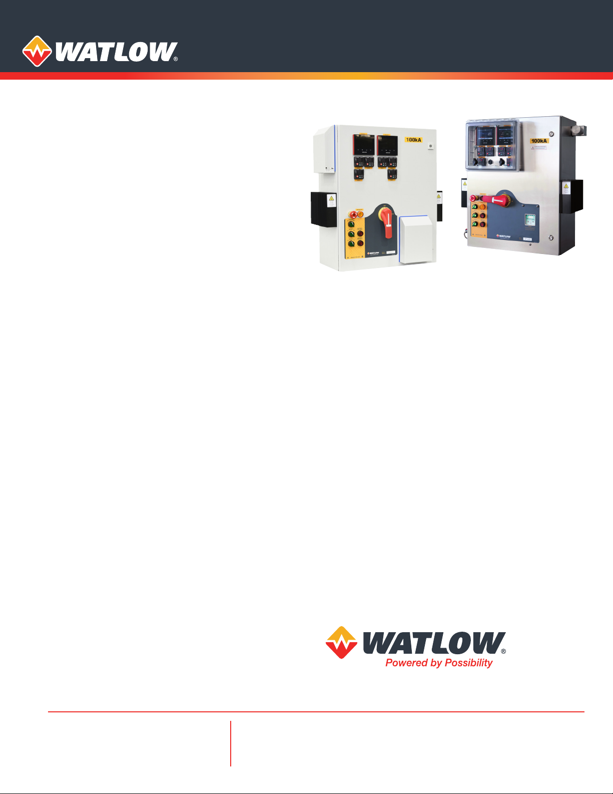
Watlow® is now offering WATCONNECT® standard control
panels that are quickly configured to your specific application
requirements and delivered within two weeks. WATCONNECT
panels integrate Watlow’s high-quality heater, sensor,
temperature controller and power controller products for a
complete thermal solution. Normally, competitive custom
panels require significantly longer lead times. The broad
range of standard features allow customers to quickly
configure panels that usually would be considered custom
for delivery within two weeks.
Watlow’s customers will be impressed with the speed and
ease of specifying, selecting, pricing, ordering and delivery.
WATCONNECT panels are flexible and scalable; there are
thousands of configurable, pre-engineered panel solutions
available.
Features and Benefits
Full documentation provided for all WATCONNECT control
panels at the time of quotation
• Eliminates lengthy approval process and phone calls
Watlow’s F4T process controllers provide data logging
and Ethernet
• Provides real time and historical data management of
process parameters
Range of standard input / output (I/O) options
• Provide the user with a higher level of monitoring
and control, assuring an efficient and safe operation
(See Communcations Interface Chart on page 4.)
WATCONNECT enclosure easily mounts to wall or frame
• Decreases installation time
Bottom, right and top power entries
• Provides multiple options for accessing and making
connections to the inside of the panel
IP-20 finger-safe construction
• Decreases chance of electrical shock for service and
maintenance personnel
Fast acting fuses
• Protects sensitive solid state components from
damaging currents
Available illuminated E-Stop
• Allows quick emergency shut down
Variety of cooling options
• Suited for a wide range of environmental conditions
Carbon steel and stainless steel enclosure materials
available
• Offers materials that are most economical for the
user’s application
Supports a wide variety of sensor inputs including ASTM
thermocouple types J, K and T, 3 wire 100 ohm RTD and
4 to 20mA process input
• Provides the customer a variety of process signals to ensure
compatibility with field equipment
For more information on WATCONNECT go to www.watlow.com/watconnect
Powered by Possibility
To be automatically connected to the nearest
North American Technical Sales Oce:
1-800-WATLOW2 • www.watlow.com
inquiry@watlow.com
©2017 Watlow Electric Manufacturing Company all rights reserved.
International Technical Sales Offices:
China +86 21 3532 8532
France +33 1 41 32 79 70
Germany +49 7253 9400 0
India +91 40 6661 2700
Italy +39 02 4588841
Japan +81 3 3518 6630
Korea +82 2 2169 2600
Mexico +52 442 256 2200
Singapore +65 6773 9488
Spain +34 91 675 1292
Taiwan +886 7 288 5168
UK +44 115 964 0777
HOU-WATC-0417
Page 2
WATCONNECT Standard Control Panels Include:
• UL®/cUL® listed control panels for installation in indoor/outdoor
and non-hazardous/hazardous locations
• Wall or frame mount enclosures with hinged door, sized to
accommodate one to four branch circuits and top, side or
bottom power entry
• Limited access and increased safety through the use of tool
operated, ¼ turn, mechanical latches that secure the hinged
door to the enclosure
• Molded case circuit breaker disconnect with through-door
interlocked handle and lock out/tag out functionality (provides
enhanced safety)
• Fused branch circuit protection ensures protection of system
load and panel components
• DIN-A-MITE® C series solid state SCR power switching
controller(s) with zero cross output firing and touch-safe
terminals provide outstanding reliability
• Through wall heat sink(s) reduces ambient temperatures within
the enclosure
• Independent high temperature limit control(s) ensures safety
and protection of the equipment being controlled
• Safety mechanical contactor(s) removes power to system load
in the event of a high limit and/or safety situation
• Process controllers come pre-programmed for the configured
options and operation, reducing overall set-up time
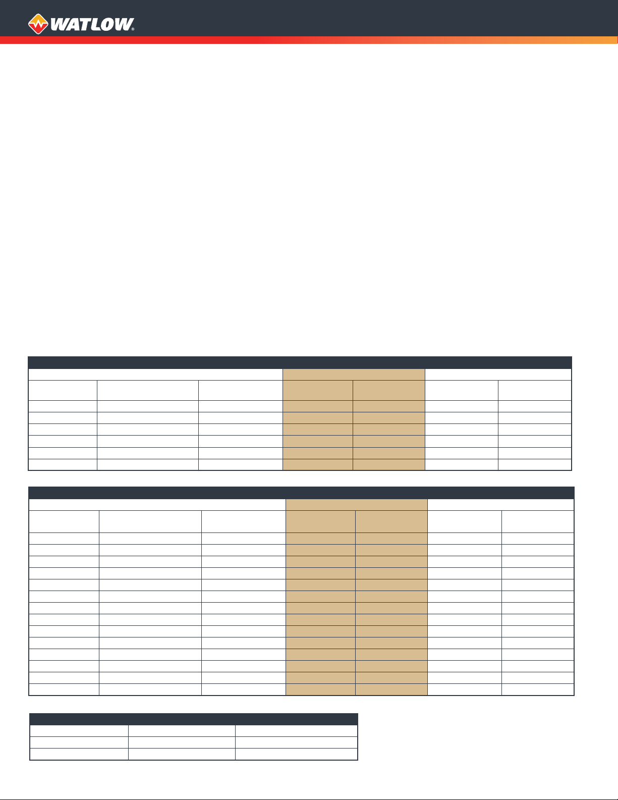
Cooling Requirements Charts
SERIES C2 (Small Non-Hazardous)
Panel Configuration Ambient Temperatures Cooling Requirements
Total Number of
Branch Circuits
1 24A (load <= 24A) Carbon steel -18°C 40°C None None
1 24A (load <= 24A) SS -18°C 35°C None No F4T
1 48A (load <= 48A) Carbon steel -18°C 30°C None No F4T
1 48A (load <= 48A) Carbon steel or SS -10°C 40°C Fans/shrouds None
2 24A (load <= 48A) Carbon steel or SS -10°C 40°C Fans/shrouds None
2 48A (load <= 96A) Carbon steel or SS -10°C 40°C Fans/shrouds None
*FLA = Full Load Amps/Branch Circuit, Total Load = (# Branch Circuits) x (Full Load Amps/Branch Circuit)
Total Number of
Branch Circuits
1 24A (load <= 24A) SS -18°C 35°C None No F4T
1 24A (load <= 24A) SS -10°C 40°C Fans/shrouds No F4T
1 24A (load <= 24A) Carbon steel -18°C 40°C None None
1 48A (load <= 48A) Carbon steel -18°C 30°C None No F4T
1 48A (load <= 48A) Carbon steel or SS -10°C 40°C Fans/shrouds None
2 24A (load <= 48A) Carbon steel -18°C 30°C None No F4T
2 24A (load <= 48A) Carbon steel or SS -10°C 40°C Fans/shrouds None
2 48A (load <= 96A) Carbon steel or SS -10°C 40°C Fans/shrouds None
3 24A (load <= 72A) Carbon steel or SS -10°C 40°C Fans/shrouds None
3 48A (load <= 144A) Carbon steel or SS -10°C 40°C Fans/shrouds None
4 24A (load <= 96A) Carbon steel or SS -10°C 40°C Fans/shrouds None
4 48A (load <= 192A) Carbon steel or SS -10°C 35°C Fans/shrouds None
4 48A (load <= 192A) Carbon steel or SS -10°C 40°C Fans/shrouds No F4T
4 48A (load <= 168A) Carbon steel or SS -10°C 40°C Fans/shrouds None
*FLA = Full Load Amps/Branch Circuit, Total Load = (# Branch Circuits) x (Full Load Amps/Branch Circuit)
Air Required SERIES C3 (Small) SERIES C5 (Medium)
PSIG 80-120* 100-120*
SCFM 25-30 40-80
*Available air ow and pressure to the panel must be sucient to maintain stated SCFM.
FLA/Branch Circuit
(Total Load)*
Panel Configuration Ambient Temperatures Cooling Requirements
FLA/Branch Circuit
(Total Load)*
SERIES C3 and C5 (Hazardous Area) Panels
Enclosure Material
SERIES C4 (Medium Non-Hazardous)
Enclosure Material
• Operator interface features:
• Illuminated control power on/off switch (one per panel) for
increased visibility of control status (status determination at
a glance)
• Illuminated heater on/off switch(s) (one for each control
loop) for increased visibility of heater power status (status
determination at a glance)
• Illuminated heater high temperature light with momentary
push to reset (allows reset of all limit controls without the
necessity of opening the enclosure door)
• Watlow process temperature control coupled with the
DIN-A-MITE power switching controller provide superior
thermal performance through tight process temperature
control
• Z-type purge system with environmental window and
temperature regulation on hazardous location panels
• Remote inputs/outputs based on process controller selection
• Field upgradable (most options)
Agency Approvals
• Preconfigured and certified to UL® Standard 508A for
non-hazardous locations
• Non-hazardous panels certified to one or more of the following:
• Type 4, 4X, 1, 12 and IP65
• Hazardous location panels certified for UL® Listed installation,
investigated to NFPA 496: 2008 and UL®698A and cUL® Listed,
investigated to NFPA 496: 208 and CAN/CSA 22.2
Min. Ambient
Operating Temp.
Min. Ambient
Operating Temp.
Max. Ambient
Operating Temp.
Operating Temp.
2
Max. Ambient
Cooling Needs Restrictions
Cooling Needs Restrictions
Page 3

Configuration Options
Control
Panel
Size
Small
SERIES
C2
C3
Hazardous
Location
NonHazardous
Hazardous
Class 1,
Div. 2,
Groups
B/C/D or
Class 1,
Zone 2,
Groups IIA/
IIB/IIC
Total # of
Control
Loops or
Zones
1 1
1 2
2 2
1 1
1 2
2 2
Total # of
Branch
Circuits
in Panel
Voltage
Supply
240V, 480V
or 600V
3-phase,
50/60Hz
4 wire
(3 power,
1 ground)
240V, 480V
or 600V
3-phase,
50/60Hz
4 wire
(3 power,
1 ground)
(external
120V single
phase
necessary for
purge
operation)
Total #
(Type) of
Process
Controllers
Up to 2
(EZ-ZONE®
PM6 or PM4,
F4T)
Up to 2
(EZ-ZONE PM6
or PM4, F4T)
Total
Process +
Limit
Controllers Notes and Restrictions
Up to 4
(1 process
w/up to
3 limits) or
(2 process
w/1 limit
each)
Up to 4
(1 process
w/up to
3 limits) or
(2 process
w/1 limit
each)
1. Shorted SCR not available
2. See process controller and
communications interface charts
for available features
1. Shorted SCR not available
2. See process controller and
communications interface charts
for available features
Medium
C4
C5
NonHazardous
Hazardous
Class 1,
Div. 2,
Groups
B/C/D or
Class 1,
Zone 2,
Groups
IIA/IIB/IIC
1 1
1 2
1 3
1 4
2 2
2 4
1 1 240V, 480V
1 2
1 3
1 4
2 2
2 4
240V, 480V
or 600V
3-phase,
50/60Hz
4 wire
(3 power,
1 ground)
or 600V
3-phase,
50/60Hz
4 wire
(3 power,
1 ground)
(external
120V single
phase
necessary
for purge
operation)
Up to 2
(EZ-ZONE
PM4, F4T)
Up to 2
(EZ-ZONE
PM4, F4T)
Up to 8
(up to
2 process +
up to 3 limits
for each
control loop/
zone
Up to 8
(up to
2 process +
up to 3 limits
for each
control loop/
zone
See process controller and
communications interface charts for
available features
See process controller and
communications interface charts for
available features
WATCONNECT®, DIN-A-MITE® and EZ-ZONE® are registered trademarks of
Watlow Electric Manufacturing Company.
UL® and cUL® are registered trademarks of Underwriter’s Laboratories, Inc.
3
Page 4

Process Controller Chart
Available Process Controllers
Small
(C2 or C3 SERIES)
Available Options/Features EZ-ZONE
PM6
Integrated Limit X X X X X
Single Sensor or Outlet Control X X X X X
Cascade Process Control X X Integrated limit not available with cascade or dierential
Dierential Process Control X X Integrated limit not available with cascade or dierential
Shorted SCR Detection X
Remote I/O (See Communications
Interface Chart)
Local Ethernet Connectivity X X RJ45 Ethernet jack on door standard on all F4Ts
Remote Copper Ethernet
Connectivity
Remote Copper/Fiber Ethernet
Connectivity
Total Number of Controllers Needed = Total
EZ-ZONE
PM4 F4T
X X X X On EZ-ZONE PM4 - Remote set point feature (within
X X Via optional Ethernet switch mounted within enclosure
X X Via optional Ethernet switch mounted within enclosure
Number of Control Loops or Zones
Medium
(C4 or C5
SERIES)
EZ-ZONE
PM4 F4T
Notes/Restrictions
process control options
process control options
Remote I/O) not available with integrated limit
Communications Interface Chart - Standard Features by Controller Type Chart
Per Control Loop/
Function
Remote I/O: Dig In - Remote Shutdown Per loop/zone Std. Std.
Remote I/O: Dig Out - Heater Hi Limit Status Per loop/zone Std. Std.
Remote I/O: Dig Out - Heater Enabled Status Per loop/zone Std. Std.
Remote I/O: Analog Out - Process Temp Retransmit
Remote I/O: Analog In - Remote Set Point Per loop/zone Std.* Std.
Remote I/O: Dig Out - Common Alarm System Std. Std.
Remote I/O: Dig Out - Purge Loss System Std. Std.
Front RJ45 Ethernet Jack System Std.
Data Logging System (per controller) Std.
Standard Copper Remote Ethernet Connection System Available option
Fiber Remote Ethernet Connection System Available option
* Note: Remote SP not available with integrated limit.
Zone or System
Per loop/zone Std. Std.
EZ-ZONE PM6
Process Controller
EZ-ZONE PM4
Process Controller
F4T Process
Controller
4
Page 5

Dimensional Drawings
A
REVISIONS
ZONE
REV.
DESCRIPTION
1
PRELIMINARY RELEASE
2/24/2017
8
7
6
5
4
3
2
1
2.17 in.
(55 mm)
19.69 in.
(500 mm)
2.17 in.
(55 mm)
18.11 in.
(460 mm)
10.24 in.
(260 mm)
19.69 in.
(500 mm)
18.11 in.
(460 mm)
24.56 in.
(624 mm)
22.05 in.
(560 mm)
A
REVISIONS
ZONE
REV.
DESCRIPTION
DATE
APPROVED
1
PRELIMINARY RELEASE
2/24/2017
JJACKSON
D
C
6
5
4
3
2
1
10.24 in.
(260 mm)
19.69 in.
(500 mm)
18.11 in.
(460 mm)
24.56 in.
(624 mm)
22.05 in.
(560 mm)
A
REVISIONS
ZONE
REV.
DESCRIPTION
DATE
APPROVED
1
PRELIMINARY RELEASE
2/24/2017
JJACKSON
D
C
4
3
2
1
19.69 in.
(500 mm)
18.11 in.
(460 mm)
24.56 in.
(624 mm)
22.05 in.
(560 mm)
REVISIONS
ZONE
REV.
DESCRIPTION
DATE
APPROVED
1
PRELIMINARY RELEASE
2/24/2017
JJACKSON
D
C
3
2
1
REVISIONS
ZONE
REV.
DESCRIPTION
2
PRELIMINARY RELEASE
8
7
6
5
4
3
2
A
3.97 in.
(101 mm)
19.69 in.
(500 mm)
2.87 in.
(73 mm)
13.70 in.
(348 mm)
3.66 in.
(93 mm)
18.11 in.
(460 mm)
Ø 0.39 in.
(10 mm)
T YP.
21.06 in.
(535 mm)
REVISIONS
ZONE
REV.
DESCRIPTION
DATE
APPROVED
2
PRELIMINARY RELEASE
2/23/2017
JJACKSON
D
C
4
3
2
1
B
A
3.66 in.
(93 mm)
18.11 in.
(460 mm)
24.81 in.
(630 mm)
22.05 in.
(560 mm)
Ø 0.39 in.
(10 mm)
T YP.
REVISIONS
ZONE
REV.
DESCRIPTION
DATE
APPROVED
2
PRELIMINARY RELEASE
2/23/2017
JJACKSON
D
C
6
5
4
3
2
1
B
A
13.70 in.
(348 mm)
3.66 in.
(93 mm)
18.11 in.
(460 mm)
24.81 in.
(630 mm)
22.05 in.
(560 mm)
Ø 0.39 in.
(10 mm)
T YP.
REVISIONS
ZONE
REV.
DESCRIPTION
DATE
APPROVED
2
PRELIMINARY RELEASE
2/23/2017
JJACKSON
D
C
3
2
1
B
C2 SERIES, Small, Non-Hazardous Location
C3 SERIES, Small, Hazardous Location
23.62 in.
(600 mm)
1.25 in.
(31 mm)
T YP.
2.17 in.
(55 mm)
Left Side View
9.78 in.
(248 mm)
19.69 in.
(500 mm)
18.11 in.
(460 mm)
10.24 in.
(260 mm)
Right Side View
2.17 in.
(55 mm)
23.62 in.
(600 mm)
1.25 in.
(32 mm)
T YP.
10.24 in.
(260 mm)
Left Side View
3.45 in.
(88 mm)
19.69 in.
(500 mm)
13.70 in.
(348 mm)
Right Side View
2.87 in.
(73 mm)
22.05 in.
(560 mm)
21.06 in.
(535 mm)
24.81 in.
(630 mm)
22.05 in.
(560 mm)
24.56 in.
(624 mm)
3.97 in.
(101 mm)
3.66 in.
(93 mm)
A
18.11 in.
(460 mm)
Front View
A
Front View
19.69 in.
(500 mm)
18.11 in.
(460 mm)
Rear View
Ø 0.39 in.
(10 mm)
T YP.
Rear View
5
Page 6

Dimensional Drawings
SCR1
SCR2
A
REVISIONS
ZONE
REV.
DESCRIPTION
DATE
APPROVED
3 PRELIMINARY RELEASE
3/23/2017
JJACKSON
D
C
8
7
6
5
4
3
2
1
B
2.29 in.
(58 mm)
23.62 in.
(600 mm)
2.25 in.
(57 mm)
Air
Outlet
Port
Air
Inlet
Port
12.39 in.
(315 mm)
21.34 in.
(542 mm)
31.10 in.
(790 mm)
A
REVISIONS
ZONE
REV.
DESCRIPTION
DATE
APPROVED
3 PRELIMINARY RELEASE
3/23/2017
JJACKSON
D
C
4
3
2
1
B
21.34 in.
(542 mm)
31.10 in.
(790 mm)
SCR1
SCR2
A
REVISIONS
ZONE
REV.
DESCRIPTION
DATE
APPROVED
3
PRELIMINARY RELEASE
3/23/2017
JJACKSON
D
C
6
5
4
3
2
1
B
12.39 in.
(315 mm)
21.34 in.
(542 mm)
31.10 in.
(790 mm)
REVISIONS
ZONE
REV.
DESCRIPTION
DATE
APPROVED
3
PRELIMINARY RELEASE
3/23/2017
JJACKSON
D
C
3
2
1
B
A
REVISIONS
ZONE
REV.
DESCRIPTION
DATE
APPROVED
3
PRELIMINARY RELEASE
3/27/2017
JJACKSON
D
C
8
7
6
5
4
3
2
1
B
2.87 in.
(73 mm)
23.62 in.
(600 mm)
2.87 in.
(73 mm)
27.36 in.
(695 mm)
3.97 in.
(101 mm)
12.39 in.
(315 mm)
21.34 in.
(542 mm)
4.02 in.
(102 mm)
31.10 in.
(790 mm)
A
REVISIONS
ZONE
REV.
DESCRIPTION
DATE
APPROVED
3
PRELIMINARY RELEASE
3/27/2017
JJACKSON
D
C
4
3
2
1
B
21.34 in.
(542 mm)
4.02 in.
(102 mm)
31.10 in.
(790 mm)
A
REVISIONS
ZONE
REV.
DESCRIPTION
DATE
APPROVED
3
PRELIMINARY RELEASE
3/27/2017
JJACKSON
D
C
6
5
4
3
2
1
B
12.39 in.
(315 mm)
21.34 in.
(542 mm)
4.02 in.
(102 mm)
31.10 in.
(790 mm)
REVISIONS
ZONE
REV.
DESCRIPTION
DATE
APPROVED
3
PRELIMINARY RELEASE
3/27/2017
JJACKSON
D
C
3
2
1
B
C4 SERIES, Medium, Non-Hazardous Location C5 SERIES, Medium, Hazardous Location
11.75 in.
(298 mm)
10.96 in.
(278 mm)
2.29 in.
(58 mm)
12.39 in.
(315 mm)
11.75 in.
(298 mm)
11 in.
(278 mm)
3.45 in.
(88 mm)
12.39 in.
(315 mm)
(760 mm)
1.25 in.
(32 mm)
29.92 in.
2.29 in.
(58 mm)
Outlet
SCR3
Left Side View
Air
Port
SCR4
23.62 in.
(600 mm)
SCR2
SCR1
Right Side View
2.25 in.
(57 mm)
1.06 in.
(27 mm)
29.92 in.
(760 mm)
Left Side View
2.87 in.
(73 mm)
23.62 in.
(600 mm)
Right Side View
2.87 in.
(73 mm)
27.36 in.
(695 mm)
3.97 in.
(101 mm)
4.02 in.
(102 mm)
A
Front View
21.34 in.
(542 mm)
Air
Inlet
Port
Front View
21.34 in.
(542 mm)
A
31.10 in.
(790 mm)
Rear View
6
Rear View
31.10 in.
(790 mm)
 Loading...