

Page 1
Using Watlow® Products with SpecView
Addendum to SpecView Manual
SCADA Software
Phone: +1 (507) 454-5300, Fax: +1 (507) 452-4507 http://www.watlow.com
1241 Bundy Boulevard, Winona, Minnesota USA 55987
Document 10-38238 Rev. A ©2019 Watlow Electric Manufacturing, Inc. All rights reserved.
July 2019
Page 2

TC
Table of Contents
Chapter 1: Introduction .................................................................................. 3
Additional Resources ................................................................................. 3
Chapter 2: About Setting up Communications ............................................ 3
Instrument Templates and Protocols .......................................................... 3
Automatic and Manual Configuration ......................................................... 4
Naming Instruments ................................................................................... 5
Saving Settings in Non-Volatile Memory .................................................... 5
Using F4T Controllers and D4T Data Loggers ........................................... 5
Using EZ-ZONE Controllers with Standard Bus ......................................... 6
Using EZ-ZONE Controllers with Modbus® ................................................ 6
Chapter 3: Setup Procedures ...................................................................... 11
Automatically Detect an F4T or D4T ........................................................ 11
Automatically Detect a New Standard Bus, 485 or 232 Network .............. 14
Manually Set up or Modify an EZ-ZONE Standard Bus Network ............. 17
Manually Set up or Modify a Modbus® RTU, 485 or 232 Network ............ 20
Manually Set up or Modify a Modbus® TCP Network ............................... 24
Adjust the Displayed Decimals ................................................................. 27
Chapter 4: Instrument Reference ................................................................ 29
F4T and D4T Instruments ........................................................................ 29
EZ-ZONE Standard Bus Instruments ....................................................... 30
EZ-ZONE Standard Bus Instrument Views .............................................. 39
EZ-ZONE Modbus® Instruments .............................................................. 43
Watlow Assembly Instruments ................................................................. 46
Generic Modbus Instruments ................................................................... 46
Part Number: 2060-2136 (replaces 0600-0056-0015)
WATLOW®, ASPYRE®, EZ-ZONE® and INTUITION® are registered trademarks of Watlow Electric Manufacturing,
Incorporated
Modbus® is a registered trademark of Schneider Automation, Incorporated.
Using Watlow Products with SpecView 2 Addendum to SpecView Manual
Page 3

Chapter 1: Introduction
2
1
SpecView is a powerful and easy-to-use Supervisory Control and Data Acquisition (SCADA) software
package. The purpose of this addendum is to quickly get you up and running using SpecView with
Watlow controllers. Chapter 2 provides a brief explanation of concepts that may not be familiar to first
time users of SpecView. Basic familiarity with these concepts is assumed in Chapter 3 which provides
procedures for getting Watlow controllers communicating with SpecView. Chapter 4 provides detailed
information regarding addressing and describes features specific to Watlow controllers.
This addendum supports SpecView version 3.
Additional Resources
In addition to this addendum the following resources are available for learning about SpecView and
other products available from Watlow:
• SpecView User Manual—available on the SpecView installation disk and at Watlow.com
navigate to Resources and Support, Technical Library: User Manuals and search on Keyword:
SpecView.
• SpecView Secrets Video Tutorials—available at Watlow.com navigate to Resources and Support,
Technical Library: Tutorials and Training and search on Keyword: SpecView.
• SpecView Frequently Asked Questions—available at Watlow.com navigate to Resources and
Support, Technical Library: Tutorials and Training and search on Keyword: SpecView.
• SpecView Software Download—the latest version of SpecView is always available at
Watlow.com navigate to Resources and Support, Technical Library: Software and Demos and
search on Keyword: SpecView.
• SpecView Software Field Upgrade Order Form—guides you through the process of adding
features to a copy of SpecView you already own. Get the form at Watlow.com navigate to
Resources and Support, Technical Library: Software and Demos and search on Keyword:
SpecView.
Chapter 2: About Setting up Communications
The following sections provide information to help you understand how to set up communications
between SpecView and Watlow controllers.
Instrument Templates and Protocols
SpecView includes support for hundreds of different devices. The protocol drivers and instrument
templates included with SpecView tell it how to communicate with specific devices. You will need to
choose the appropriate templates whenever you want to automatically or manually set up
communications between SpecView and a device.
Using Watlow Products with SpecView 3 Addendum to SpecView Manual
Page 4

There are many instrument templates grouped by communication protocol and product family that
Support for F4T and D4T
outputs in the flex modules
Support for basic operation
profiles.
Supports reads and writes to
Instruments on page 46.
Watlow EZ-ZONE
Standard Bus
EZ-ZONE PM, EZ-ZONE RM,
EZ-ZONE ST
Allows saving profiles as
Programmer ordering option.
Anafaze 16 Loop
16CLS, CLS216, 16MLS, MLS316
Anafaze 32 Loop
32MLS, MLS332
Anafaze 8 Loop
4CLS, CLS204, 8CLS, CLS208
CLS204, CLS208, CLS216,
MLS316, MLS332
Ramp/Soak Profile
programming and operation
Anafaze/AB
ANAFAZE
32MLS
Proprietary Anafaze protocol
support Watlow products. The table below lists these template groups, protocols and the Watlow models
supported by each.
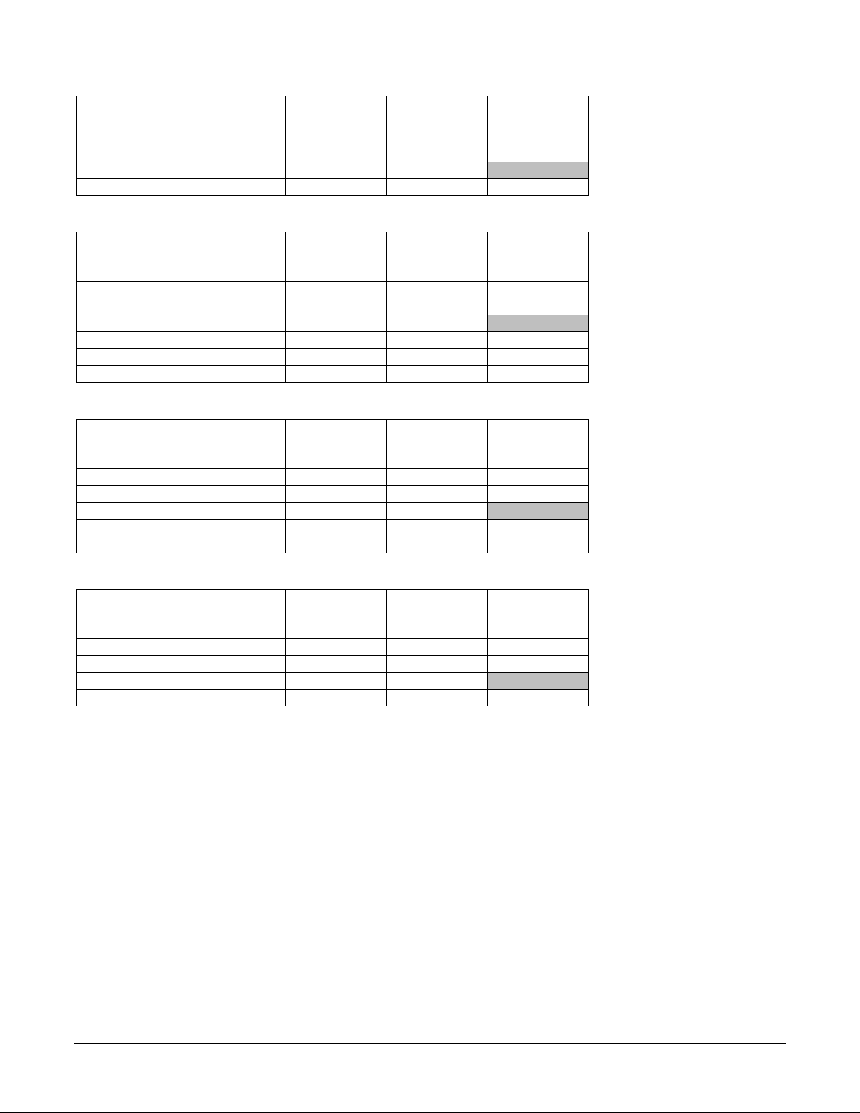
Template Group Protocol(s) Supported Watlow Models Notes
Watlow F4T & D4T
Watlow Modbus
Watlow Assembly
Watlow F4
Programmer
®
Modbus
Modbus
Standard Bus
Modbus
RTU
®
TCP
®
RTU
F4T with INTUITION
D4T with INTUITION®
®
ASPYRE
EZ-ZONE
EZ-ZONE ST, SERIES 96, 97, SD
MICRODIN, POWER SERIES,
986, 987, 988, 989
SERIES F4 Ramping
F4T with INTUITION
D4T with INTUITION
EZ-ZONE PM, EZ-ZONE RM
SERIES F4 Ramping
Power Controllers
®
PM, EZ-ZONE RM,
®
functions and inputs and
parameters in EZ-ZONE
products. See
Modbus
. Limited support for
43
programming SERIES F4
16 or 32 contiguous floatingpoint values. Intended to
minimize update time for
measurements when used
with the user-configurable
communication assemblies.
Watlow Assembly
See
Recommended for EZ-ZONE.
recipes. Requires Series F4
Standard firmware option only
EZ-ZONE
®
Instruments on page
Anafaze Ramp/Soak
Using Instruments from More than one Group or Protocol
The templates in the groups listed above that support Modbus® RTU on serial communications ports are
compatible with each other. Similarly the templates that support Modbus® TCP used over Ethernet are
compatible with each other. SpecView allows protocol-compatible templates to be used on the same
port, but you will need to help SpecView by instructing it when to do so. When there are controllers
connected to the same port that require instrument templates from different groups, you will scan once
for each of those groups to automatically detect the various devices.
If your configuration requires communicating with controllers supported by different protocols via serial
communications ports, each protocol must have its own network connected to SpecView via a separate
communications port. Support for multiple communication ports is an ordering option for SpecView,
and is field upgradeable.
Automatic and Manual Configuration
SpecView can automatically detect and set up communications with controllers. However, in some cases
it may be necessary to manually configure SpecView. This method is particularly useful if you want to
create screens and configure SpecView prior to receiving your controllers. Projects that were created
automatically can be updated by testing the communications network for new controllers. It is also
Using Watlow Products with SpecView 4 Addendum to SpecView Manual
Page 5

possible to manually add or remove controllers from any configuration whether it was created
automatically or manually. This addendum contains procedures for automatically and manually
configuring communications for the various networking options supporting Watlow controllers.
SpecView can automatically detect F4T and D4T data loggers controllers using Modbus® TCP or
Modbus® RTU and EZ-ZONE controllers using the Standard Bus protocol. When using Modbus® with
EZ-ZONE controllers create the configuration manually.
Naming Instruments
It is useful to name instruments such that you can easily relate what you see on the screen in SpecView
to your equipment and processes. You might want to use a name that:
• Indicates the controller’s function in the process
• Indicates the controller’s location in the panel
• Includes network information such as port and address
When you create a project or add instruments to one by automatically detecting controllers, SpecView
prompts you to name the instruments as it adds them. You must name any instruments that you add
manually. You can change an instrument’s name whenever you like. However, changing an instrument’s
name makes logged data associated with the old name inaccessible going forward; it is best to name
instruments up front.
Saving Settings in Non-Volatile Memory
Some Watlow controllers protect their non-volatile memory from being worn out prematurely due to
excessive use that may occur when communicating with devices such as a PLC that send the same
settings to a controller many times a second. In these controllers, the settings received via
communications can be held in volatile memory that is cleared when the controller is turned off. Since
SpecView will typically send parameter settings to a controller only when you edit a parameter on the
screen, for your convenience you can set the controller to routinely save the parameter settings that
come through communications in non-volatile memory. That way the values you set are saved even
when the controller is powered down. Consult the controller manual for the appropriate parameter,
typically called, “Non-Volatile Save”.
Using F4T Controllers and D4T Data Loggers
The instruments in the Watlow F4T & D4T group support standard and optional features in in F4Ts and
D4Ts as well as the flex modules those devices are set to expect. For details see F4T Instruments on
page 29.
Automatic Detection of F4Ts and D4Ts
When automatically detecting a network with the Watlow F4T & D4T group, SpecView reads the part
number of the F4T or D4T and adds the appropriate instruments for features including control loops,
cascade loops, profiles and alarms. Additionally, an instrument is added for each flex module the F4T or
D4T is configured to expect.
Additional Instruments Available with the Watlow F4T Driver
Because F4Ts and D3Ts offer many additional functions such as math, logic, timers and counters that
may not all be used in the application, other instruments may be manually added to a configuration to
gain access to the values and settings associated with these features.
Using Watlow Products with SpecView 5 Addendum to SpecView Manual
Page 6
Using EZ-ZONE Controllers with Standard Bus
When automatically detecting a Standard Bus network with the Watlow EZ-ZONE Standard Bus driver,
SpecView reads each device’s part number and adds the appropriate instruments. For the details see EZ-
ZONE Standard Bus Instruments on page 30.
Note! Run the 32-bit version of SpecView for compatibility with the Watlow EZ-ZONE Standard Bus
driver. This driver is not supported by the 64-bit version of SpecView.
Using EZ-ZONE Controllers with Modbus®
To configure SpecView to communicate with EZ-ZONE products via Modbus® you will select and add
appropriate instruments manually. For each instrument you must determine the correct address string.
The address string depends on the type of network and its configuration. You will add as many copies of
the instrument as needed to allow access to the desired controller features. For example, to access all
four analog inputs in an EZ-ZONE RM Control Module, you will add four EZ-ZONE Analog Input
instruments.
SpecView Instruments Supporting EZ-ZONE Devices via Modbus®
The tables in this section list the instruments that may be used with each EZ-ZONE product. Additional
tables in the EZ-ZONE Modbus® Instruments section on page 43 list each parameter included in these
instruments. Review the supported parameters carefully and determine whether they allow you to
develop a project that meets your requirements. Standard Bus communications provides access to many
more EZ-ZONE controller parameters.
Simplified Address Strings in SpecView Version 3
In previous versions of SpecView the “address string” included the controller address, number of
decimal places to display and the register offset. As of version 3 these are now entered in separate fields
in SpecView which makes setting up instruments more straight forward.
Controller or Gateway Slave Address
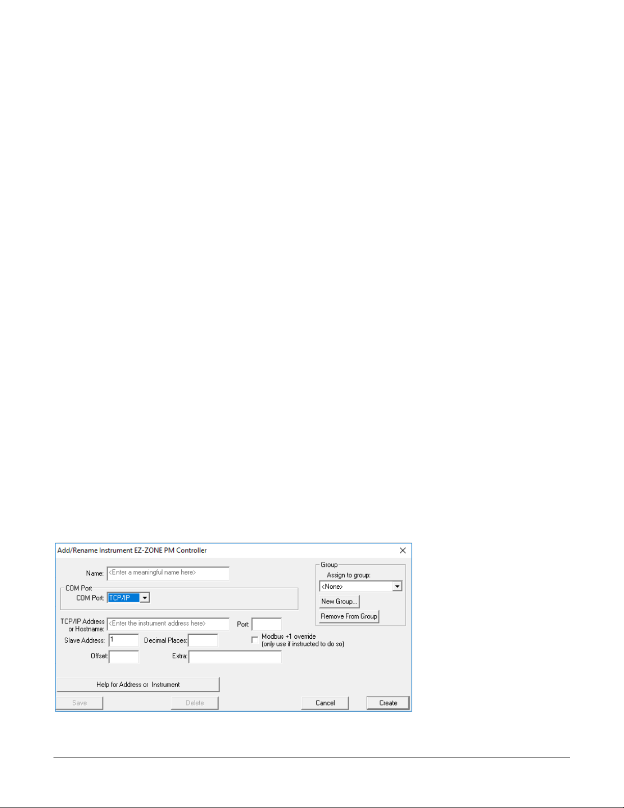
For Modbus® TCP each controller or gateway is identified by its TCP/IP Address. EZ-ZONE controllers
and gateways will respond to any valid setting (1 to 247) for the Slave Address. It is not necessary to set
each device to a unique Modbus® address, but each must have a unique and appropriate IP address. See
the figure below.
Using Watlow Products with SpecView 6 Addendum to SpecView Manual
Page 7
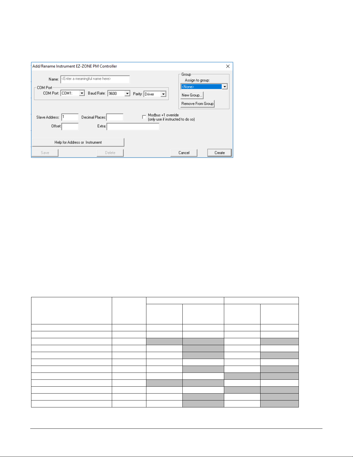
For Modbus® RTU specify the controller or gateway’s Modbus® Slave Address (1 to 247). This is set in
Data Map 1 via RUI Only1
Data Map 22
First
Address
First
Address
EZ-ZONE Alarm
1 to 2
1480
50
1450
60
EZ-ZONE Analog Input
1 to 2
360
160
360
90
EZ-ZONE Control Loop
1
N/A
N/A
1750
N/A
EZ-ZONE Communications
1
2418
N/A
2060
20
EZ-ZONE Current
1
1120
N/A
1240
N/A
EZ-ZONE Digital I/O
1 to 6
880
30
940
30
EZ-ZONE Limit
1
680
N/A
720
N/A
EZ-ZONE Profile (Map 1)**
1 to 4
6070
500
N/A
N/A
EZ-ZONE Profile (Map 2)**
1 to 4
N/A
N/A
4000
1000
EZ-ZONE Profile (ST Map 1)
1 to 4
2870
800
N/A
N/A
EZ-ZONE Profile Operation
1
2720
N/A
3800
N/A
EZ-ZONE Set Points
1
2160
N/A
1890
N/A
the controller or gateway’s Setup Communications menu. Each controller or gateway on the network
must have a unique Modbus® address. See the figure below.
Decimal Places
Specify zero (0) to display whole numbers for parameters such as process variable and set point. Specify
one (1) to display these parameters with tenths precision, two (2) to display hundredths and so on. Valid
settings range from zero (0) to four (4).
Register Address Offset
The register address offset is the sum of the First Instance Address for the specific EZ-ZONE product,
any applicable Instance Offsets and the Gateway Offset, if any. The Gateway Offset is set by the user
when the RUI Gateway or RM Access Module gateway is configured. The First Instance Address and
Instance Offsets depend on the controller’s data map setting and are supplied in the tables below for
each instrument and product.
Gateway Offset
Be careful not to set up instruments that attempt to read Modbus® registers that are mapped over by the
configuration of the gateway.
Register Addresses and Offsets for EZ-ZONE ST
Instrument Instances
Instance
Instance
Offset
Instance
Instance
Offset
1
Supported only via EZ-ZONE RUI Gateway.
2
Available with firmware version 4.0 or later.
Using Watlow Products with SpecView 7 Addendum to SpecView Manual
Page 8
Register Addresses and Offsets for EZ-ZONE PM
Data Map 1
Data Map 2
First
Address
First
Address
EZ-ZONE Alarm
1 to 4
1480
50
1880
60
EZ-ZONE Analog Input
1 to 2
360
80
360
90
EZ-ZONE Communications
1 or 2
2490
20
2970
20
EZ-ZONE Control Loop
1 to 2
1880
70
2360
70
EZ-ZONE Current
1
1120
N/A
1360
N/A
EZ-ZONE Digital I/O
1 to 12
880
30
1000
30
EZ-ZONE Limit
1
680
N/A
720
N/A
EZ-ZONE Profile (Map 1)
1 to 4
2570
500
N/A
N/A
EZ-ZONE Profile (Map 2)
1 to 4
N/A
N/A
4500
1000
EZ-ZONE Profile Operation
1
2520
N/A
4340
N/A
EZ-ZONE Set Points
1 to 2
2160
80
2640
80
First
Address1
EZ-ZONE Alarm
1480
EZ-ZONE Analog Input
360
EZ-ZONE Control Loop
1880
EZ-ZONE Set Points
2160
First
Address1
EZ-ZONE Alarm
1480
EZ-ZONE Analog Input
360
EZ-ZONE Limit
680
First
Address
EZ-ZONE Alarm
1 to 8
1740
60
EZ-ZONE Analog Input
1 to 4
360
90
EZ-ZONE Communications
1
2830
N/A
EZ-ZONE Control Loop
1 to 4
2220
70
EZ-ZONE Current
1 to 4
1380
50
EZ-ZONE Digital I/O
1 to 12
1020
30
EZ-ZONE Limit
1 to 4
720
30
EZ-ZONE Profile (Map 2)
1 to 25
5440
1000
EZ-ZONE Profile Operation
1
5280
N/A
EZ-ZONE Set Points
1 to 4
2500
80
EZ-ZONE Sub Routine
1 to 15
30440
860
Instrument Instances
Instance
Instance
Offset
Register Addresses for EZ-ZONE Express Controller
Instrument
1
PM Express has only one instance each.
Instance
Instance
Instance
Offset
Register Addresses for EZ-ZONE Express Limit
Instrument
1
PM Express has only one instance each.
Instance
Register Addresses and Offsets for EZ-ZONE RMC Modules
Instrument Instances
Instance
Instance
Offset
Using Watlow Products with SpecView 8 Addendum to SpecView Manual
Page 9
Register Addresses and Offsets for EZ-ZONE RME Modules
First
Address
EZ-ZONE Alarms
1 to 8
1440
60
EZ-ZONE Communications
1
2170
N/A
EZ-ZONE Digital I/O
1 to 24
360
30
First
Address
EZ-ZONE Alarms
1 to 24
2660
60
EZ-ZONE Analog Input
1 to 16
380
90
EZ-ZONE Communications
1
6510
N/A
EZ-ZONE Control Loop
1 to 16
4100
70
EZ-ZONE Digital I/O
1 to 12
1820
30
EZ-ZONE Set Points
1 to 16
5220
80
First
Address
EZ-ZONE Alarms
1 to 16
2530
60
EZ-ZONE Analog Input
1 to 12
410
90
EZ-ZONE Communications
1
3500
N/A
EZ-ZONE Digital I/O
1 to 12
1850
30
EZ-ZONE Limit
1 to 12
1490
30
First
Address
EZ-ZONE Alarms
1 to 16
2500
60
EZ-ZONE Analog Input
1 to 16
380
90
EZ-ZONE Communications
1
3470
N/A
EZ-ZONE Digital I/O
1 to 12
1820
30
Instrument Instances
Instance
Instance
Offset
Register Addresses and Offsets for EZ-ZONE RMH Modules
Instrument Instances
Instance
Instance
Offset
Register Addresses and Offsets for EZ-ZONE RML Modules
Instrument Instances
Instance
Instance
Offset
Register Addresses and Offsets for EZ-ZONE RMS Modules
Instrument Instances
Instance
Instance
Offset
Address Example 1: Analog Input 1 in an EZ-ZONE ST via Modbus® RTU
For an EZ-ZONE ST communicating with SpecView directly (no gateway) via Modbus® RTU, use the
First Instance Address for the EZ-ZONE Analog Input, 360 to read analog input 1. If the controller’s
address on the 485 network is 2, set the following properties for the instrument:
• Slave Address: 2
• Offset: 360
Note that we must use data map 2 because data map 1 is not supported by SpecView for EZ-ZONE STs
without a gateway.
Address Example 2: Analog Input 2 in an EZ-ZONE ST via Modbus® RTU
For an EZ-ZONE Analog Input instrument supporting analog input 2 in the ST controller from example
1, set the following properties for the instrument:
• Slave Address: 2
• Offset: 450
Using Watlow Products with SpecView 9 Addendum to SpecView Manual
Page 10

The offset is 450 because 360 is the address for the first analog input and you add the offset, 90, to reach
• EZ-ZONE PM Controller
• EZ-ZONE ST Controller
• EZ-ZONE ST Profiling
the second input.
Address Example 3: EZ-ZONE PM Controllers via an EZ-ZONE RUI Gateway with Modbus® TCP
Consider three EZ-ZONE PM controllers configured for data map 2 and connected to an EZ-ZONE RUI
Gateway with the local/remote gateway offsets set to 0, 4000 and 8000 respectively. To determine the
register address offset for an EZ-ZONE Set Points instrument to support the second control loop in the
third EZ-ZONE PM, locate the First Instance Address and the Instance Offset. These are 2640 and 80
respectively. Add these together for second control loop and add the gateway offset for the third
controller: 2640 + 80 + 8000 = 10720. So the register address offset is 10720. Set the following
properties for this instrument:
• TCP/IP Address or Hostname: 10.3.37.105
• Slave Address: 1
• Offset: 10720
Keep in mind that with Modbus® TCP the EZ-ZONE PM will respond to any slave address.
EZ-ZONE Modbus® Profile Instruments
The instruments supporting programming profiles include 10 steps each. Therefore, the instance offsets
indicated above are ten times the instance offsets indicated for the steps in the controller manuals.
Old EZ-ZONE Modbus® Instruments
The following instruments are included in the Watlow Modbus® instrument group, but are no longer
described in this document. They are not maintained or tested for use with later versions. They are
provided for backwards compatibility only.
• EZ-ZONE PM Limit
• EZ-ZONE PM Profiling
Note: These instruments support data map 1 only.
• EZ-ZONE Gateway ST Controller
• EZ-ZONE Gateway ST Profiling
Using ASPYRE Power Controllers with Modbus®
Connect a 485 port on the PC to port 2 on the ASPYRE power controller via RS-485 Modbus RTU. To
configure SpecView to communicate with ASPYRE products via Modbus® RTU from the Watlow
Modbus group in the New Instruments list select and add one ASPYRE DT instrument manually per
power controller. Configure communications with each instrument with the information listed below.
• COM Port: the serial port to on the PC which the ASPYRE power controller is connected
• Baud Rate: per the setting of the ASPYRE RS-485 port to which the PC is connected
• EZ-ZONE PM Profiling
• Parity: Driver
• Slave Address: the address of the ASPYRE power controller on the 485 network (also known as
station address)
• Decimal Places: 0
• Modbus +1 override: not selected
• Offset: leave blank
• Extra: leave blank
Using Watlow Products with SpecView 10 Addendum to SpecView Manual
Page 11
To create a configuration automatically:
1) For each F4T / D4T:
3
Chapter 3: Setup Procedures
The following sections provide procedures for establishing communications between SpecView and
Watlow controllers.
Automatically Detect an F4T or D4T
The following procedure guides you through the process of configuring SpecView to communicate with
Watlow F4T controllers and D4T data loggers via Modbus® TCP or Modbus® RTU. It is assumed that
the controllers are connected correctly via Ethernet or one or more of the computer’s serial
communications ports. To add a controller to an existing configuration, see Manually Set up or Modify a
Modbus® RTU, 485 or 232 Network on page 20 or Manually Set up or Modify a Modbus® TCP Network
on page 24.
Modbus® RTU:
• Set all controllers to
the same baud rate
• Set each controller to a
unique Modbus
Modbus® TCP:
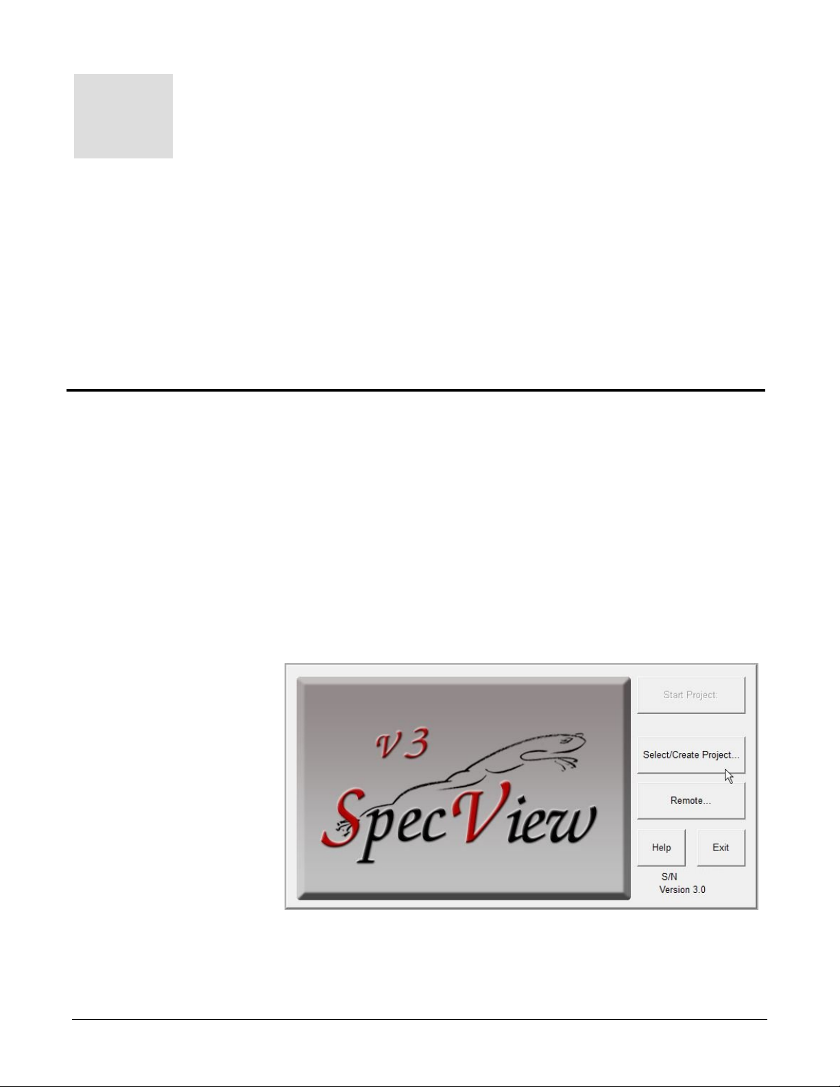
2) Launch SpecView
Address
• Set Parity to None.
• Set Modbus Word
Order to Low High
• Modbus Data Map: 1
• Set each controller to a
unique IP address.
• Make sure Modbus
TCP is enabled.
and click through
any informational
dialogs.
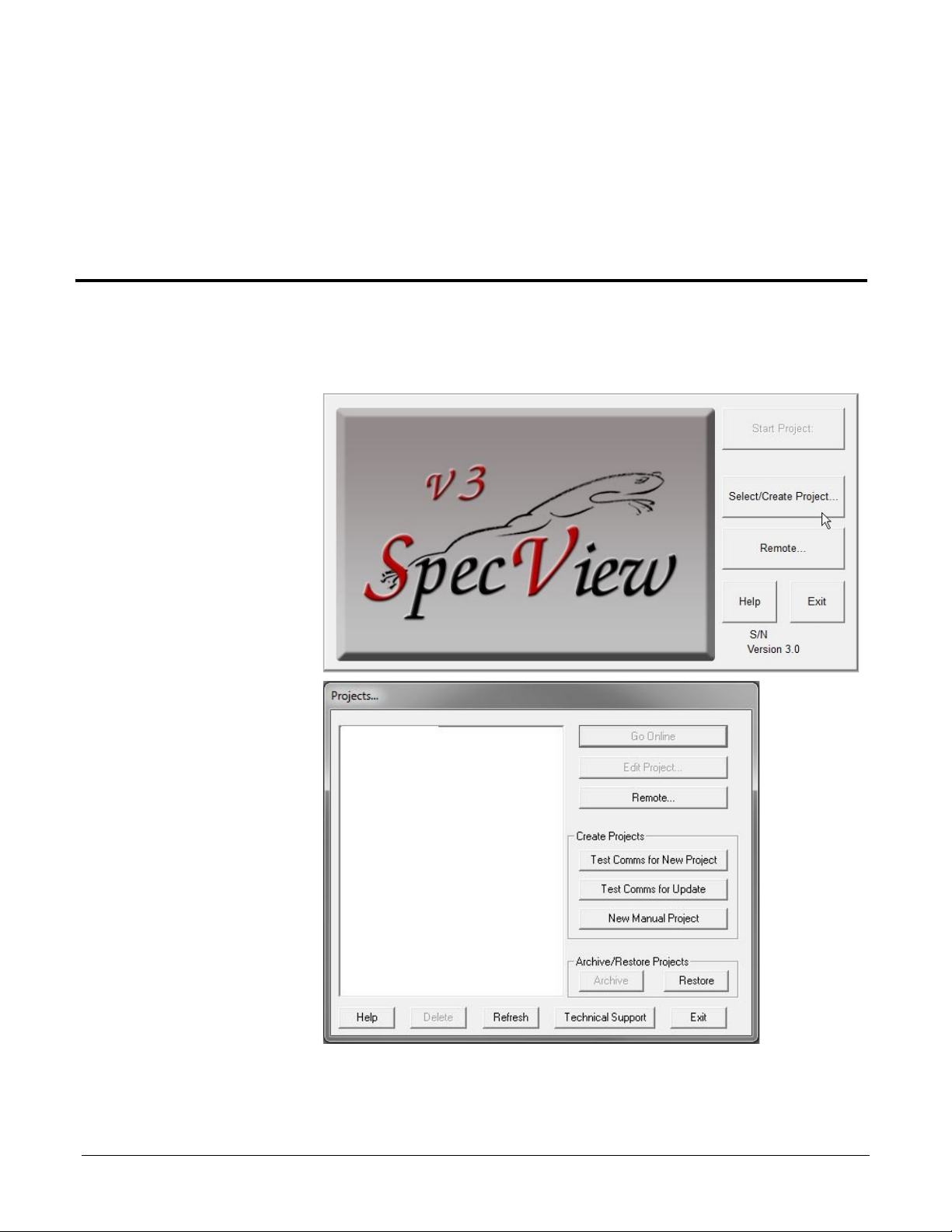
3) At the splash screen,
click Select/Create
Project…
Using Watlow Products with SpecView 11 Addendum to SpecView Manual
Page 12
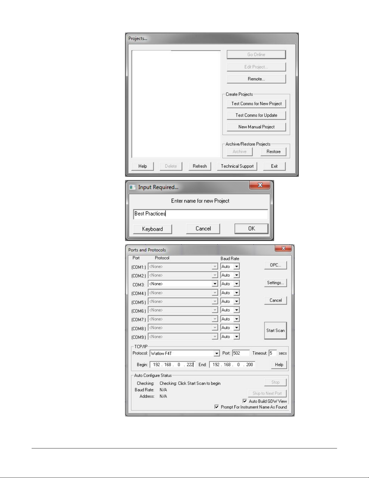
4) In the Projects
dialog click Test
5) Enter a name for the
7) For the Port to
Comms for New
Project.
project.
6) Click OK.
which the
controllers are
attached, under
Protocol choose the
Watlow F4T & D4T
template group.
8) For TCP/IP enter
Begin and End
addresses to limit
the range of
addresses scanned.
9) Click Start Scan.
Using Watlow Products with SpecView 12 Addendum to SpecView Manual
Page 13
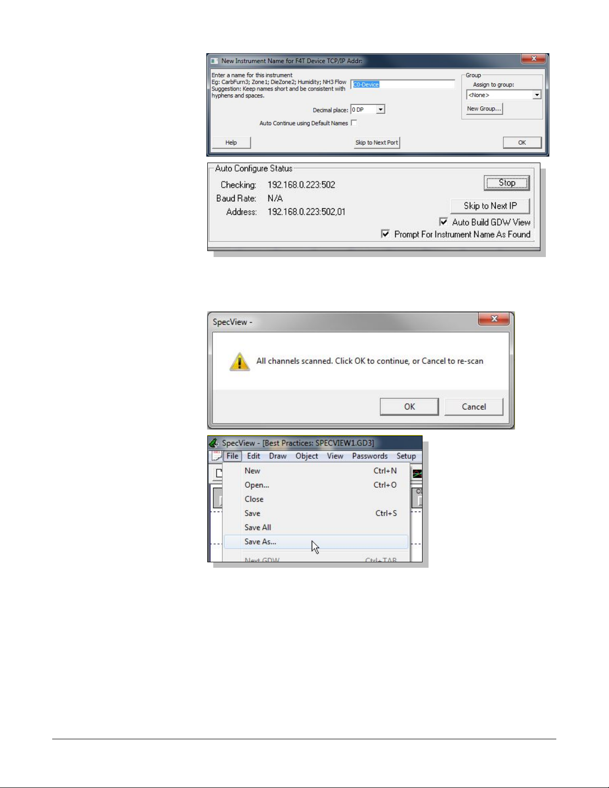
10) For each instrument
SpecView detects,
11) Once SpecView has
12) To scan another
14) To save the GDW:
enter a name and set
Decimal Places or
click OK to accept
the default settings.
scanned all the
addresses with F4T
controllers and D4T
data loggers, click
Stop or, if there are
more ports to scan,
click Skip to Next
Port or Skip to
Next IP.
template group,
click Cancel and
repeat from step 7
above for the next
template group.
13) Click OK.
• From the File menu,
choose Save As.
• Enter a File name for
the GDW.
• Click Save.
Using Watlow Products with SpecView 13 Addendum to SpecView Manual
Page 14
Automatically Detect a New Standard Bus, 485 or 232
To create a project automatically:
3) Launch SpecView.
5) In the Projects
Network
The following procedure guides you through the process of configuring SpecView to communicate with
Watlow controllers via Standard Bus, 232 and 485 serial communications. It is assumed that the
controllers are connected correctly to one or more of the computer’s serial communications ports. To
add a controller to an existing configuration, see Manually Set up or Modify an EZ-ZONE Standard Bus
Network on page 17 or Manually Set up or Modify a Modbus® RTU, 485 or 232 Network on page 20.
1) Set all controllers to the same baud rate. (Not necessary for Standard Bus.)
2) Set each controller to a unique address or zone number.
Note! Use the 32-bit
version of
SpecView with the
Watlow EZ-ZONE
Standard Bus driver.
4) At the splash screen,
click Select/Create
Project…
dialog click Test
Comms for New
Project.
Using Watlow Products with SpecView 14 Addendum to SpecView Manual
Page 15

6) Enter a name for the
project.
8) For the Port to
10) For each instrument
7) Click OK.
which the
controllers are
attached, choose the
appropriate template
group driver in
Protocol. See the
table below.
9) Click Start Scan.
SpecView detects,
enter a name and set
Decimal Places or
click OK to accept
the default settings.
Using Watlow Products with SpecView 15 Addendum to SpecView Manual
Page 16

For this Controller… Choose this Template
Watlow EZ-ZONE
Standard Bus
SERIES 96, 97, SD
986, 987, 988, 989
For the SERIES F4 Profiling controller, scan twice,
page 20.
16CLS, 16MLS,
CLS216, MLS316
CLS200 and MLS300 Standard and Ramp/Soak
20.
32MLS, MLS332
Anafaze 32 Loop
32MLS (Anafaze protocol)
Anafaze/AB
11) If another template
13) To save the GDW:
Group for Protocol…
Notes
EZ-ZONE PM, RM or ST
MICRODIN,
POWER SERIES,
SERIES F4 Ramping
8CLS, CLS208
4CLS, CLS204
1
Scan with the Watlow F4 Programmer driver only if the F4 programmer option is enabled in the SpecView key.
Watlow Modbus
Watlow Modbus
Watlow F4 Programmer
Anafaze 16 Loop
Anafaze 8 Loop
once with each template group. Add the F4 Cascade
instrument manually if desired. See
1
or Modify a Modbus
firmware options. For controllers with Ramp/Soak to
add the Anafaze Profile Status and the desired
Anafaze Profile instruments. See
Modify a Modbus
®
RTU, 485 or 232 Network on
®
RTU, 485 or 232 Network on page
Manually Set up
Manually Set up or
group must be
scanned, click
Cancel and repeat
this procedure from
step 8 for the next
template group.
12) Click OK.
• From the File menu,
choose Save As.
• Enter a File name for
the GDW.
• Click Save.
Using Watlow Products with SpecView 16 Addendum to SpecView Manual
Page 17

Manually Set up or Modify an EZ-ZONE Standard Bus
To create a manual project:
1) Launch SpecView.
4) Enter a name for the
Network
The following procedures guide you through the process of manually creating a configuration for a
Standard Bus network and adding devices to this configuration. Use this procedure when the EZ-ZONE
controllers are not available to detect automatically.
Note! Use the 32-bit
version of SpecView
with the Watlow EZZONE Standard Bus
driver.
2) At the splash screen,
click Select/Create
Project…
3) Click New Manual
Project.
project.
5) Click OK.
Using Watlow Products with SpecView 17 Addendum to SpecView Manual
Page 18

To add one or more instruments to a project:
1) Open the Graphical
Display Window in
3) In New Instruments
EZ-ZONE PM
Watlow EZ-ZONE Standard Bus
See the PM table on page 31.
EZ-ZONE PM Express Controller2
Watlow EZ-ZONE Standard Bus
PM Express Controller
z
EZ-ZONE PM Express Limit1
Watlow EZ-ZONE Standard Bus
PM Express Limit_
z
EZ-ZONE RMA Access Module
Watlow EZ-ZONE Standard Bus
See the RMA table on page 31.
EZ-ZONE RMC Control Module
Watlow EZ-ZONE Standard Bus
See the RMC table on page 32.
EZ-ZONE RMH High-Density
Control Module
EZ-ZONE RML High-Density Limit
Module
EZ-ZONE RMS High-Density
Scanner Module
EZ-ZONE RME Expansion Module
Watlow EZ-ZONE Standard Bus
See the RME table on page 37.
See the Function Block table on page
38.
ST Controller
z
ST Profiling3
z
the edit mode if it is
not already open.
2) Click the Templates
button.
List click to
expand Watlow EZ-
ZONE Standard
Bus.
4) Select the instrument
you want to add. (See
the table below.)
5) Click Create Inst.
For This Controller… From this Template Group…
EZ-ZONE RM Function Blocks Watlow EZ-ZONE Standard Bus
EZ-ZONE ST Watlow EZ-ZONE Standard Bus
1
Replace “z” in the address with the zone number (also known as the standard bus address).
2
For PM model numbers of the form PMxxxxx-AAAABxx.
3
Add these instruments for a controller that includes the ramp and soak or profiling option.
Add These
Instruments…
Watlow EZ-ZONE Standard Bus See the RMH on page 34.
Watlow EZ-ZONE Standard Bus See the RML table on page 35.
Watlow EZ-ZONE Standard Bus See the RMS table on page 36.
With
Address...
1
Using Watlow Products with SpecView 18 Addendum to SpecView Manual
Page 19

6) In the Add/Rename
Instrument dialog
12) To add an instrument view
13) To add a variable to the
14) To save the GDW:
type a Name for the
instrument.
7) Select the COM Port.
8) Enter the Address.
See the table above.
9) Click Create.
10) Repeat from step 4 for
each instrument to be
added.
11) Close the New Instruments
List.
to the GDW, drag the
instrument from the list to
the GDW.
GDW:
• Open the Variables list
• Expand the instrument
by clicking .
• Drag the parameter from
the list to the GDW.
• From the File menu,
choose Save.
• Enter a File name for
the GDW.
• Click Save.
Using Watlow Products with SpecView 19 Addendum to SpecView Manual
Page 20

Manually Set up or Modify a Modbus® RTU, 485 or 232
To create a new project manually:
1) Launch SpecView.
4) Enter a name for the
Network
The following procedures guide you through the process of manually creating a configuration for a
Modbus® RTU, 485 or 232 network and adding devices to this configuration. Use this procedure when
the controllers are not available to detect automatically, when you want to add a new controller to an
existing configuration and for creating configurations that communicate with EZ-ZONE controllers via
Modbus® RTU.
2) At the splash screen,
click Select/Create
Project…
3) Click New Manual
Project.
project.
5) Click OK.
Using Watlow Products with SpecView 20 Addendum to SpecView Manual
Page 21

To add one or more instruments to a project:
1) Open the Project in
the edit (on-line)
3) In New Instruments
6) In the Add/Rename
mode if it is not
already open.
2) Click the Templates
button.
List click to
expand the group that
includes the
instrument you want
to add. See the table
below.
4) Select the instrument
you want to add.
5) Click Create Inst.
Instrument dialog
type a Name for the
instrument.
7) Select the Port.
8) Set the Baud Rate.
9) Enter the Slave
Address set in the
controller.
10) Enter the Decimal
Places.
11) For EZ-ZONE
controllers enter the
Offset. See Using EZ-
ZONE Controllers
with Modbus® on
page 6.
Using Watlow Products with SpecView 21 Addendum to SpecView Manual
Page 22

For This Controller…
F4T or D4T
Watlow F4T & D4T
See F4T Instruments on page 29.
ASPYRE DT (See Using ASPYRE Power
Controllers with Modbus® on page 10
EZ-ZONE PM
EZ-ZONE PM Express Controller
EZ-ZONE PM Express Limit
EZ-ZONE RM
EZ-ZONE ST
MICRODIN
Watlow Modbus
MicroDin
SERIES 96
Watlow Modbus
Series 96
SERIES 97
Watlow Modbus
SERIES 97 Limit
SERIES SD Controller
SERIES SD Profiling1
SERIES SD Limit
Watlow Modbus
SERIES SD Limit
986, 987, 988, 989
Watlow Modbus
Watlow 988
POWER SERIES
Watlow Modbus
Watlow Power Series
Watlow F4
F4 Cascade
Watlow F4 Programmer
Watlow F4 Program2
Any
Generic Modbus
See Generic Modbus Instruments on page 46.
16CLS, 16MLS,
CLS216, MLS316
MLS CPU
Yes
MLS(16)Ch (1 per loop)
Yes
n (n = loop)
MLS CPU
Yes
MLS(32)Ch (1 per loop)
Yes
n (n = loop)
8CLS, CLS208
4CLS, CLS204
MLS CPU
Yes
CLS(8)Ch (1 per loop)
Yes
n (n = loop)
Anafaze Profile Status1
Yes
Anafaze Profile A to
as desired to program) 1
12) For Anafaze
13) Click Create.
ASPYRE DT Watlow Modbus
From this Template
Group…
Add These Instruments…
Watlow Modbus
Watlow Assembly
SERIES SD Watlow Modbus
SERIES F4 Ramping
1
Add this instrument for a controller that includes the ramp and soak or profiling option.
2
Add the Watlow F4 Program instrument only if the F4 programmer option is enabled in the SpecView key.
For This
Controller…
From this Template
Group…
Anafaze 16 Loop
Watlow Modbus
Add These Instruments…
See SpecView Instruments Supporting EZ-ZONE
Devices via Modbus
See Watlow Assembly Instruments on page 46.
Modbus +1
Override option
®
on page 6.
With Offset…
32MLS, MLS332 Anafaze 32 Loop
CLS204, CLS208,
CLS216, MLS316,
MLS332
1
Add these instruments for a controller that includes the ramp and soak or profiling option.
instruments only:
• Check Modbus +1
• Enter the Offset, if
required.
14) Repeat from step 3 as
needed to add
additional
instruments.
Anafaze 8 Loop
Anafaze Ramp/Soak
Anafaze Profile Q (as many
Yes
Using Watlow Products with SpecView 22 Addendum to SpecView Manual
Page 23

15) Close the New
Instruments List.
16) To add an instrument
17) To add a variable to the
18) To save the GDW:
view to the GDW,
click-and-drag the
instrument from the
list to the GDW.
GDW:
• Open the Variables list
• Expand the instrument
by clicking .
• Click-and-drag the
parameter from the list
to the GDW.
• From the File menu,
choose Save.
• Enter a File name for
the GDW.
• Click Save.
Using Watlow Products with SpecView 23 Addendum to SpecView Manual
Page 24

Manually Set up or Modify a Modbus® TCP Network
To create a new project manually:
1) Launch SpecView.
3) Click New Manual
4) Enter a name for the
The following procedures guide you through the process of manually configuring SpecView to
communicate with F4T and EZ-ZONE controllers via Modbus® TCP and adding instruments to the
project.
2) At the splash screen,
click Select/Create
Project…
Project.
configuration
5) Click OK.
Using Watlow Products with SpecView 24 Addendum to SpecView Manual
Page 25

To add one or more instruments to a project:
1) Open the Project in
the edit (on-line)
3) In New Instruments
F4T
Watlow F4T
See F4T Instruments on page 29.
EZ-ZONE PM
EZ-ZONE PM Express Controller
EZ-ZONE PM Express Limit
EZ-ZONE RM
EZ-ZONE ST
Any
Generic Modbus
See Generic Modbus Instruments on page 46.
6) In the Add/Rename
mode if it is not
already open.
2) Click the Templates
button.
List click to
expand the group that
includes the
instrument you want
to add. See the table
below.
4) Select the instrument
you want to add.
Locate them in the
sections referenced
below.
5) Click Create Inst.
For This Controller…
Instrument dialog for
COM Port select
TCP/IP.
7) In the TCP/IP
Address field enter
the IP Address.
8) In Decimal Places
enter the number of
decimals to show.
From this Template
Group…
Watlow Modbus
Add These Instruments…
See Using EZ-ZONE Controllers with Modbus on
page 6.
With Address
and Offset…
Using Watlow Products with SpecView 25 Addendum to SpecView Manual
Page 26

9) In Offset enter the
necessary address
13) To add instrument views
14) To add a variable to the
15) To save the GDW:
offset, if any. See the
section referenced in
the table above.
10) Click Create.
11) Repeat from step 3 as
needed to add additional
instruments.
12) Close the New Instruments
List.
to the GDW, for each:
• In the Variables list
select the instrument.
• Click Add Item.
GDW:
• Expand the instrument
by clicking .
• Click-and-drag the
parameter from the list
to the GDW.
• From the File menu,
choose Save As.
• Enter a File name for
the GDW.
• Click Save.
Using Watlow Products with SpecView 26 Addendum to SpecView Manual
Page 27

Adjust the Displayed Decimals
To make the number of decimal places displayed in SpecView match the controller display:
1) Set the decimal
controller.
EZ-ZONE ST, PM, RM
Any
N/A
dEC
0 to 3
MICRODIN
Any
Decimal Point
(No Display)
0 or 1
Thermocouple, RTD
Decimal Pt 1
dEC1
0 or 1
Process
Decimal Pt 1
dEC1
0 to 3
SERIES 97
Any
Decimal 1
dEC1
0 or 1
SERIES SD Controller
SERIES SD Limit
Thermocouple, RTD
See Note (1)
dEC
0 or 1
Process (mA, mV, V)
See Note (2)
dEC
0 to 3
POWER SERIES
Not available
Decimal 1
Decimal 2
Input 1 DecPlaces
Input 3 DecPlaces
Input 1 DecPlaces
Input 3 DecPlaces
CLS, MLS,
CLS200, MLS300
Thermocouple, RTD
Precision
Disp Format
1
Linear
Precision
Disp Format
0 to 4
The following procedure describes how to adjust the number of decimal places displayed in SpecView.
Note this procedure does not apply to EZ-ZONE controllers communicating with SpecView by Watlow
EZ-ZONE Standard Bus because with that protocol the decimal places are automatically displayed
according to the controller setting.
When communicating with F4T or EZ-ZONE controllers via Modbus® the Decimal Places setting in
SpecView determines the precision with which numbers are displayed; it does not shift the decimal
placement relative to the digits. For older Watlow controllers it is necessary to set the Decimal Places
setting according to the controller setting so that numbers are scaled correctly and not off by orders of
magnitude.
setting in the
controller as desired.
(See the table for
details about each
For This Controller… For Sensor Type…
Parameter in
SpecView…
Parameter in
Controller…
Available
Decimals
SERIES 96
986, 987, 988, 989 Any
Thermocouple, RTD,
Wet Bulb-Dry Bulb
SERIES F4 Ramping
Process
Notes:
For a SERIES SD with a thermocouple or RTD set the Decimals (Ctlr Temp Display Only) parameter, the
(1)
Decimals (SpecView and Ctlr Prcs Display) parameter and SpecView for the same number of decimals.
(2) For a SERIES SD with a process input (mA, mV or V) set the Decimals (SpecView and Ctlr Prcs Display)
parameter and SpecView for the same number of decimals.
Input 2 DecPlaces
Input 2 DecPlaces
dEC1 0 to 3
Choose
Decimal
Choose
Decimal
0 or 1
0 to 3
Using Watlow Products with SpecView 27 Addendum to SpecView Manual
Page 28

2) Open the project and
from the File menu
6) Set the Decimal
Set…
For…
0
Whole Numbers
1
Tenths
2
Hundredths
3
Thousandths
4
Ten-thousandths
8) To save the GDW:
choose Edit Mode
(go offline).
3) Click to open the
Variables list.
4) Select the instrument.
5) Click Properties.
Places as desired:
7) Click Save.
• From the File menu,
choose Save.
Note: The possible decimal settings may depend on other controller settings such as the sensor type.
Not all parameters are affected by the decimal places setting.
Using Watlow Products with SpecView 28 Addendum to SpecView Manual
Page 29

Chapter 4: Instrument
4
Reference
This chapter describes the instruments and instrument views supporting Watlow products.
F4T and D4T Instruments
The following sections list the instruments that support F4T controllers and D4T data loggers.
Automatic Detection with the Watlow F4T & D4T Instrument Group
When automatically detecting a network with the Watlow F4T & D4T instrument group, SpecView
reads each controller’s part number and adds the appropriate instruments. When adding instruments
manually, refer to the table below which correlates F4T and D4T configuration codes with the
instruments that support the corresponding features. The table also lists the Offset setting, if required, for
each instrument.
For part numbers matching… Add… Instrument Name (Description) Offset
F4Txxxxxxxxxxxx
F4Txxx(D, E or F)xxxxxxxx
F4Txxx(B, C, E or F)xxxxxxxx F4T Special OP Function (used for compressor control) 1
F4TxxxxxxxxUxxx
U = (1, 2, 3, 4, 7, 8, 9, B or C)
F4TxxxxxxxxUxxx
U = (2, 3, 4, 8, 9 or C)
F4Txxxxxxxx(3, 4 or 9)xxx
F4Txxxxxxxx4xxx
F4TxxxxxxxxUxxx
U = (6, 7, 8, 9, A. B or C)
F4Txxxxxxxx(A, B or C)xxx F4T Cascade Loop (setup and monitor cascade loop 2) 2
F4T Device (real time clock, global and diagnostic settings)
F4T Alarms (14) (alarm settings for alarms 1 to 14)
F4T Profile Editor
F4T Profile Engine (monitor and operate ramp-soak profiles)
F4T Profile List (name and start command for each profile)
F4T Control Loop (setup and monitor control loop 1) 1
F4T Control Loop (setup and monitor control loop 2)
F4T Control Loop (setup and monitor control loop 3)
F4T Control Loop (setup and monitor control loop 4)
F4T Cascade Loop (setup and monitor cascade loop 1) 1
2
3
4
D4Txxxxxxxxxxxx
Flex modules which the F4T or
D4T is configured to expect
*The offset for a flex module instrument is simply the slot number in which the module is expected.
Using Watlow Products with SpecView 29 Addendum to SpecView Manual
D4T Device (real time clock, global and diagnostic settings)
D4T Alarms (14) (alarm settings for alarms 1 to 14)
FMxx-xxxx-xxxx... (corresponding to the module configuration
code)
*
Page 30

Additional Instruments Available in the Watlow F4T & D4T Instrument Group
The table below lists the other instruments that may be manually added to a configuration to gain access
to additional values and settings in F4T controllers and D4T data loggers.
Instrument Names Description Offset1
F4T Alarm / D4T Alarm One alarm function block 1 to 14
F4T Alarms (14) / D4T Alarms (14) 14 alarm function blocks 1
F4T Compare / D4T Compare One compare function block 1 to 16
F4T Counter / D4T Counter One counter function block 1 to 16
F4T Limit One limit function block 1 to 6
F4T Linearization / D4T Linearization One linearization function block 1 to 8
F4T Logic / D4T Logic One logic function block 1 to 24
F4T Math / D4T Math One math function block 1 to 24
F4T Process Value / D4T Process Value One process value function block 1 to 8
F4T Special OP Functions/ D4T Special OP Functions One special output function block 1 to 4
F4T Timer / D4T Timer One timer function block 1 to 16
F4T Variable / D4T Variable One variable function block 1 to 24
F4T Variables (24)/ D4T Variables (24) 24 variable function blocks
Notes
1
With the exception of Variables (24) and Alarms (14) instruments which support variables 1 to 24 and alarms 1
to 14 respectively, each of these instruments supports a single function block. Set the address offset in the
instrument properties to the function block number you want. For example, for Counter 2, set the offset to 2.
EZ-ZONE Standard Bus Instruments
The tables in this section list the part number options for EZ-ZONE controllers correlating them with the
instruments that support the corresponding features. The tables also list the format of the addresses for
each instrument which are entered when configuring SpecView manually.
Addresses for Standard Bus EZ-ZONE Instruments
The addresses entered into SpecView for each instrument are the zone number (also known as standard
bus address) and, for some instruments, an offset. The tables indicate which instruments require the
offset.
Standard Bus instrument addresses consist of:
• “z” the Zone number or Standard Bus address (1 to 9, A, B, C, D, E, F, H or J)
• ; a semicolon when an offset is required
• the offset or instance number required for some instruments
Note: For the individual Function Block instruments the offset is shown as “o” in the Address column.
In place of the “o” enter the instance number of the function block. For example, for Alarm 7 in an RM
at zone 5 the Address is, “5;7”.
Using Watlow Products with SpecView 30 Addendum to SpecView Manual
Page 31

EZ-ZONE PM Standard Bus Instruments
diagnostic)
This table describes the instruments supporting the EZ-ZONE PM controllers and limits including the
PM Express models.
Model
PM
For part numbers
matching…
PMxxxxx-xxxxVxx
(V = A, C, D or F)
PMxUxxx-xxxxVxx
(U = C, R, B, J, N, E or S)
(V = A, C, D or F)
PMxxxxx-x(C or J)xxVxx
(V = A, C, D or F)
PMxxxxx-x(L or M)xxVxx
(V = A, C, D or F)
PMxxxxx-x(R or P)xxVxx
(V = A, C, D or F)
PMxxxxx-xTxxVxx
(V = A, C, D or F)
Add… Instrument Name
(Description)
PM Zone (alarm, digital input,
output, global and diagnostic)
Control-Loop (setup and
monitor loop 1)
Control-Loop (setup and
monitor loop 2)
Address1 Named2
z Cn-EZ-z Zone
z;1 Cn-EZ-z Ctlr-1
z;2 Cn-EZ-z Ctlr-2
Integrated Limit z Cn-EZ-z Limit
Auxiliary Input z;2 Cn-EZ-z AI-2
Single Current Input
z;1 Cn-EZ-z CT-1
PMxxxxx-xxxx(C or F)xx PM Function Blocks z Cn-EZ-z FB
PMxUxxx-xxxxVxx
(U = L, M or D)
(V = A, C, D or F)
PMxUxxx-xxxxxxx
(U = R, B, N or E)
Stand Alone and RM Limit
(not in PM with a control loop)
PM Profiling (program and
operate ramp-soak profiles)
z;1 Cn-EZ-z Limit-1
z Cn-EZ-z Prof
PMxCxxx-xxxx(B or E)xx PM Express Controller z Cn-EZ-z Ctlr
PMxLxxx-xxxx(B or E)xx PM Express Limit_ z Cn-EZ-z Limit
PMxTxxx-xxxxxxx PM Timer z Cn-EZ-z Timer
Notes
1
Replace “z” in the address with the zone number (also known as Standard Bus address).
2
Instrument names are shown as automatically detected by SpecView where “n” is replaced by the port number
and “z” is replaced by the zone number (also known as Standard Bus address).
EZ-ZONE RMA Standard Bus Instruments
This table describes the instruments supporting EZ-ZONE RM Access Modules.
Model
For part numbers
matching…
RMAx-xxxx-xxxx
RMA
RMAx-xYxx-xxxx
(Y = 2, 3, 5, or 6)
RMAx-xxxD-xxxx
Notes
1
Replace “z” in the address with the zone number (also known as Standard Bus address).
2
Instrument names are shown as automatically detected by SpecView where “n” is replaced by the port number
and “z” is replaced by the zone number (also known as Standard Bus address).
Add… Instrument Name
(Description)
RMA Zone (global and
Address1 Named2
z Cn-EZ-z Zone
RMA Gateway z Cn-EZ-z GW
RM Data Logging
z Cn-EZ-z Log
Using Watlow Products with SpecView 31 Addendum to SpecView Manual
Page 32

EZ-ZONE RMC Standard Bus Instruments
This table describes the instruments supporting EZ-ZONE RM Control Modules.
Model
RMC
For part numbers
matching…
RMCxxxxxxxxxxxx
RMCxxxxxxxxxxxx RMC Outputs 1 to 8 z Cn-EZ-z Out
RMCxxxxxxxxxxxx RM Function Blocks4 z Cn-EZ-z FB
RMCYxxxxxxxxxxx
(Y = 1, 2, 3 or 4)
RMCxx(1 or 2)xxxxxxxxx
RMCxxxx(1 or 2)xxxxxxx
RMCxxxxxx(1 or 2)xxxxx
RMC(5 or 6)xxxxxxxxxxx
RMCxx(5 or 6)xxxxxxxxx
RMCxxxx(5 or 6)xxxxxxx
RMCxxxxxx(5 or 6)xxxxx
RMC7xxxxxxxxxxx
RMCxx7xxxxxxxxx
RMCxxxx7xxxxxxx
RMCxxxxxx7xxxxx
RMCxx(R or P)xxxxxxxxx
RMCxxxx(R or P)xxxxxxx
RMCxxxxxx(R or P)xxxxx
RMCxxxxxxxCxxxx Digital I/O 07 to 12 z Cn-EZ-z DIO 07-12
RMC(3 or 4)xxxxxxxxxxx
RMC(3 or 4)xxxxxxxxxxx
RMC(3 or 4)xxxxxxxxxxx
Add… Instrument Name
(Description)
RM Zone (alarms, actions
globals and diagnostics)
Control-Loop (setup and
monitor control loop 1)
Control-Loop (setup and
monitor control loop 2)
Control-Loop (setup and
monitor control loop 3)
Control-Loop (setup and
monitor control loop 4)
Stand Alone and RM Limit
(set up and monitor limit 1)
Stand Alone and RM Limit
(set up and monitor limit 2)
Stand Alone and RM Limit
(set up and monitor limit 3)
Stand Alone and RM Limit
(set up and monitor limit 4)
Single Current Input (set up
and monitor current input 1)
Single Current Input (set up
and monitor current input 2)
Single Current Input (set up
and monitor current input 3)
Single Current Input (set up
and monitor current input 4)
Auxiliary Input (set up and
monitor analog input 2)
Auxiliary Input (set up and
monitor analog input 3)
Auxiliary Input (set up and
monitor analog input 4)
RMC Profile Operation (setup
and operate ramp and soak)
RMC Profiles 1 to 5 (program
profiles steps 1 to 50)
RMC Profiles 6 to 10
(program steps 51 to 100)
3
Address1 Named2
z Cn-EZ-z Zone
z;1 Cn-EZ-z Ctlr-1
z;2 Cn-EZ-z Ctlr-2
z;3 Cn-EZ-z Ctlr-3
z;4 Cn-EZ-z Ctlr-4
z;1 Cn-EZ-z Lim-1
z;2 Cn-EZ-z Lim-2
z;3 Cn-EZ-z Lim-3
z;4 Cn-EZ-z Lim-4
z;1 Cn-EZ-z CT-1
z;2 Cn-EZ-z CT-2
z;3 Cn-EZ-z CT-3
z;4 Cn-EZ-z CT-4
z;2 Cn-EZ-z AI-2
z;3 Cn-EZ-z AI-3
z;4 Cn-EZ-z AI-4
z Cn-EZ-z Prof Ops
z Cn-EZ-z Prof 1-5
z Cn-EZ-z Prof 6-10
Using Watlow Products with SpecView 32 Addendum to SpecView Manual
Page 33

Model
(program steps 101 to 150)
(sub routine steps 51 to 100)
150)
For part numbers
matching…
RMC(3 or 4)xxxxxxxxxxx
Add… Instrument Name
(Description)
RMC Profiles 11 to 15
Address1 Named2
z Cn-EZ-z Prof 11-15
RMC Profiles 16 to 20
(program steps 151 to 200)
RMC Profiles 21 to 25
(program steps 201 to 250)
RMC Sub Routines 1 to 5
(sub routine steps 1 to 50)
RMC Sub Routines 6 to 10
z Cn-EZ-z Prof 16-20
z Cn-EZ-z Prof 21-25
z Cn-EZ-z SR-1-5
z Cn-EZ-z SR-6-10
RMC
(cont.)
RMC(3 or 4)xxxxxxxxxxx
RMC(3 or 4)xxxxxxxxxxx
RMC(3 or 4)xxxxxxxxxxx
RMC(3 or 4)xxxxxxxxxxx
RMC Sub Routines 11 to 15
RMC(3 or 4)xxxxxxxxxxx
(sub routine steps 101 to
z Cn-EZ-z SR-11-15
Notes
1
Replace “z” in the address with the zone number (also known as Standard Bus address).
2
Instrument names are shown as automatically detected by SpecView where “n” is replaced by the port number
and “z” is replaced by the zone number (also known as Standard Bus address).
3
The RM Zone instrument includes eight instances of alarms. Several types of EZ-ZONE RM modules support
more alarm instances. Add a Function Block: Alarm instrument manually for each additional instance you want to
access.
4
The RM Function Block instrument includes four or eight instances of each type of function block. Several types
of EZ-ZONE RM modules support more function block instances than that. To access these additional instances,
add an individual function block instrument for each block you want to access.
Using Watlow Products with SpecView 33 Addendum to SpecView Manual
Page 34

EZ-ZONE RMH Standard Bus Instruments
This table describes the instruments supporting EZ-ZONE RM High-Density Control Modules.
Model
RMH
For part numbers
matching…
RMHx-xxxx-xxxx
RMHx-(1 or 2)xxx-xxxx
RMHx-x(1 or 2)xx-xxxx
RMHx-xx(1 or 2)x-xxxx
Add… Instrument Name
(Description)
RM Zone (alarms, actions
globals and diagnostics)
3
Address1 Named2
z Cn-EZ-z Zone
RM Function Blocks4 z Cn-EZ-z FB
Control-Loop (setup and
monitor control loop 1)
Control-Loop (loop 2)
z;1 Cn-EZ-z Ctlr-1
z;2 Cn-EZ-z Ctlr-2
Control-Loop (loop 3) z;3 Cn-EZ-z Ctlr-3
Control-Loop (loop 4) z;4 Cn-EZ-z Ctlr-4
Control-Loop (loop 5) z;5 Cn-EZ-z Ctlr-5
Control-Loop (loop 6) z;6 Cn-EZ-z Ctlr-6
Control-Loop (loop 7) z;7 Cn-EZ-z Ctlr-7
Control-Loop (loop 8) z;8 Cn-EZ-z Ctlr-8
Control-Loop (loop 9) z;9 Cn-EZ-z Ctlr-9
Control-Loop (loop 10) z;10 Cn-EZ-z Ctlr-10
Control-Loop (loop 11) z;11 Cn-EZ-z Ctlr-11
Control-Loop (loop 12) z;12 Cn-EZ-z Ctlr-12
Control-Loop (loop 13) z;13 Cn-EZ-z Ctlr-13
Control-Loop (loop 14) z;14 Cn-EZ-z Ctlr-14
RMHx-xxx(1 or 2)-xxxx
Control-Loop (loop 15) z;15 Cn-EZ-z Ctlr-15
Control-Loop (loop 16) z;16 Cn-EZ-z Ctlr-16
RMHx-xxCx-xxxx Digital I/O 01 to 06 z Cn-EZ-z DIO 01-06
RMHx-xx(J, F or L)x-xxxx RM Outputs 1 to 4 z Cn-EZ-z Out 01-04
RMHx-xxxC-xxxx Digital I/O 07 to 12 z Cn-EZ-z DIO 07-12
RMHx-xxx(J, F or L)-xxxx RM Outputs 7 to 10 z Cn-EZ-z Out 07-10
Notes
1
Replace “z” in the address with the zone number (also known as Standard Bus address).
2
Instrument names are shown as automatically detected by SpecView where “n” is replaced by the port number
and “z” is replaced by the zone number (also known as Standard Bus address).
3
The RM Zone instrument includes eight instances of alarms. Several types of EZ-ZONE RM modules support
more alarm instances. Add a Function Block: Alarm instrument manually for each additional instance you want to
access.
4
The RM Function Block instrument includes four or eight instances of each type of function block. Several types
of EZ-ZONE RM modules support more function block instances than that. To access these additional instances,
add an individual function block instrument for each block you want to access.
Using Watlow Products with SpecView 34 Addendum to SpecView Manual
Page 35

EZ-ZONE RML Standard Bus Instruments
This table describes the instruments supporting EZ-ZONE RM High-Density Limit Modules.
Model
RML
For part numbers
matching…
RMLx-xxxx-xxxx
RMLx-x(5 or 6)xx-xxxx
RMLx-xx(5 or 6)x-xxxx
RMLx-xxCx-xxxx
Add… Instrument Name
(Description)
RM Zone (alarms, actions
globals and diagnostics)
3
Address1 Named2
Z Cn-EZ-z Zone
RM Function Blocks4 Z Cn-EZ-z FB
Stand Alone and RM Limit
(set up and monitor limit 1)
Stand Alone and RM Limit
(set up and monitor limit 2)
Stand Alone and RM Limit
(set up and monitor limit 3)
Stand Alone and RM Limit
(set up and monitor limit 4)
Stand Alone and RM Limit
(set up and monitor limit 1)
Stand Alone and RM Limit
(set up and monitor limit 2)
Stand Alone and RM Limit
(set up and monitor limit 3)
Stand Alone and RM Limit
(set up and monitor limit 4)
Stand Alone and RM Limit
(set up and monitor limit 1)
Stand Alone and RM Limit
(set up and monitor limit 2)
Stand Alone and RM Limit
(set up and monitor limit 3)
Stand Alone and RM Limit
(set up and monitor limit 4)
Digital I/O 01 to 06
z;1 Cn-EZ-z Lim-1
z;2 Cn-EZ-z Lim-2
z;3 Cn-EZ-z Lim-3
z;4 Cn-EZ-z Lim-4
z;5 Cn-EZ-z Lim-5
z;6 Cn-EZ-z Lim-6
z;7 Cn-EZ-z Lim-7
z;8 Cn-EZ-z Lim-8
z;9 Cn-EZ-z Lim-9
z;10 Cn-EZ-z Lim-10
z;11 Cn-EZ-z Lim-11
z;12 Cn-EZ-z Lim-12
z Cn-EZ-z DIO 01-06
RMLx-xxJx-xxxx
RMLx-xxxx-xxxx
RM Outputs 1 to 4
Digital I/O 07 to 12
z Cn-EZ-z Out 01-04
z Cn-EZ-z DIO 07-12
Notes
1
Replace “z” in the address with the zone number (also known as Standard Bus address).
2
Instrument names are shown as automatically detected by SpecView where “n” is replaced by the port number
and “z” is replaced by the zone number (also known as Standard Bus address).
3
The RM Zone instrument includes eight instances of alarms. Several types of EZ-ZONE RM modules support
more alarm instances. Add a Function Block: Alarm instrument manually for each additional instance you want to
access.
4
The RM Function Block instrument includes four or eight instances of each type of function block. Several types
of EZ-ZONE RM modules support more function block instances than that. To access these additional instances,
add an individual function block instrument for each block you want to access.
Using Watlow Products with SpecView 35 Addendum to SpecView Manual
Page 36

EZ-ZONE RMS Standard Bus Instruments
This table describes the instruments supporting EZ-ZONE RM High-Density Scanner Modules.
Model
RMS
For part numbers
matching…
RMSx-xxxx-xxxx
RMSx-x(R or P)xx-xxxx
RMSx-xx(R or P)x-xxxx
RMSx-xxx(R or P)-xxxx
RMSx-xxCx-xxxx
Add… Instrument Name
(Description)
RM Zone (alarms, actions
globals and diagnostics)
2
Address1 Named2
z Cn-EZ-z Zone
RM Function Blocks3 z Cn-EZ-z FB
Auxiliary Input (input 1) z;1 Cn-EZ-z AI-1
Auxiliary Input (input 2) z;2 Cn-EZ-z AI-2
Auxiliary Input (input 3)
Auxiliary Input (input 4)
Auxiliary Input (input 5)
Auxiliary Input (input 6)
Auxiliary Input (input 7)
Auxiliary Input (input 8)
Auxiliary Input (input 9)
Auxiliary Input (input 10)
Auxiliary Input (input 11)
Auxiliary Input (input 12)
Auxiliary Input (input 13)
Auxiliary Input (input 14)
Auxiliary Input (input 15)
Auxiliary Input (input 16)
Digital I/O 01 to 06
z;3 Cn-EZ-z AI-3
z;4 Cn-EZ-z AI-4
z;5 Cn-EZ-z AI-5
z;6 Cn-EZ-z AI-6
z;7 Cn-EZ-z AI-7
z;8 Cn-EZ-z AI-8
z;9 Cn-EZ-z AI-9
z;10 Cn-EZ-z AI-10
z;11 Cn-EZ-z AI-11
z;12 Cn-EZ-z AI-12
z;13 Cn-EZ-z AI-13
z;14 Cn-EZ-z AI-14
z;15 Cn-EZ-z AI-15
z;16 Cn-EZ-z AI-16
z Cn-EZ-z DIO 01-06
RMSx-xx(J, F or L)x-xxxx RM Outputs 1 to 4 z Cn-EZ-z Out 01-04
RMSx-xxx(C or B)-xxxx
Digital I/O 07 to 12
z Cn-EZ-z DIO 07-12
RMSx-xxx(J, F or L)-xxxx RM Outputs 7 to 10 z Cn-EZ-z Out 07-10
Notes
1
Replace “z” in the address with the zone number (also known as Standard Bus address).
2
Instrument names are shown as automatically detected by SpecView where “n” is replaced by the port number
and “z” is replaced by the zone number (also known as Standard Bus address).
3
The RM Zone instrument includes eight instances of alarms. Several types of EZ-ZONE RM modules support
more alarm instances. Add a Function Block: Alarm instrument manually for each additional instance you want to
access.
4
The RM Function Block instrument includes four or eight instances of each type of function block. Several types
of EZ-ZONE RM modules support more function block instances than that. To access these additional instances,
add an individual function block instrument for each block you want to access.
Using Watlow Products with SpecView 36 Addendum to SpecView Manual
Page 37

EZ-ZONE RME Standard Bus Instruments
This table describes the instruments supporting EZ-ZONE RM Expansion Modules.
Model
RME
For part numbers
matching…
RMEx-xxxx-xxxx
RMEx-xxxx-xxxx RM Function Blocks3 z Cn-EZ-z FB
RMEx-Cxxx-xxxx Digital I/O 01 to 06 z Cn-EZ-z DIO 01-06
RMEx-Txxx-xxxx
RMEx-Vxxx-xxxx
(V = J, K, F or L)
RMEx-xCxx-xxxx Digital I/O 07 to 12 z Cn-EZ-z DIO 07-12
RMEx-xTxx-xxxx
RMEx-xVxx-xxxx
(V = J, K, F or L)
Add… Instrument Name
(Description)
RM Zone (alarms, actions
globals and diagnostics)
Single Current Input (set up
and monitor current input 1)
Single Current Input (set up
and monitor current input 2)
Single Current Input (set up
and monitor current input 3)
Single Current Input (set up
and monitor current input 4)
RM Outputs 1 to 4 z Cn-EZ-z Out 01-04
Single Current Input (set up
and monitor current input 5)
Single Current Input (set up
and monitor current input 6)
Single Current Input (set up
and monitor current input 7)
Single Current Input (set up
and monitor current input 8)
RM Outputs 7 to 10 z Cn-EZ-z Out 07-10
2
Address1 Named2
z Cn-EZ-z Zone
z;1 Cn-EZ-z CT-1
z;2 Cn-EZ-z CT-2
z;3 Cn-EZ-z CT-3
z;4 Cn-EZ-z CT-4
z;5 Cn-EZ-z CT-5
z;6 Cn-EZ-z CT-6
z;7 Cn-EZ-z CT-7
z;8 Cn-EZ-z CT-8
RMEx-xxCx-xxxx Digital I/O 13 to 18 z Cn-EZ-z DIO 13-18
RMEx-xxTx-xxxx
RMEx-xxVx-xxxx
(V = J, K, F or L)
RMEx-xxxC-xxxx
Single Current Input (set up
and monitor current input 9)
Single Current Input (set up
and monitor current input 10)
Single Current Input (set up
and monitor current input 11)
Single Current Input (set up
and monitor current input 12)
RM Outputs 13 to 16 Z Cn-EZ-z Out 13-16
Digital I/O 19 to 24
z;9 Cn-EZ-z CT-9
z;10 Cn-EZ-z CT-10
z;11 Cn-EZ-z CT-11
z;12 Cn-EZ-z CT-12
z Cn-EZ-z DIO 19-24
Using Watlow Products with SpecView 37 Addendum to SpecView Manual
Page 38

Model
and monitor current input 13)
(set up
For part numbers
matching…
Add… Instrument Name
(Description)
Single Current Input (set up
Address1 Named2
z;13 Cn-EZ-z CT-13
RME
RMEx-xxxT-xxxx
Single Current Input (set up
and monitor current input 14)
Single Current Input
and monitor current input 15)
Single Current Input (set up
and monitor current input 16)
z;14 Cn-EZ-z CT-14
z;15 Cn-EZ-z CT-15
z;16 Cn-EZ-z CT-16
RMEx-xxx(F or L)-xxxx RM Outputs 19 to 22 z Cn-EZ-z Out 19-22
Notes
1
Replace “z” in the address with the zone number (also known as Standard Bus address).
2
Instrument names are shown as automatically detected by SpecView where “n” is replaced by the port number
and “z” is replaced by the zone number (also known as Standard Bus address).
3
The RM Zone instrument includes eight instances of alarms. Several types of EZ-ZONE RM modules support
more alarm instances. Add a Function Block: Alarm instrument manually for each additional instance you want to
access.
4
The RM Function Block instrument includes four or eight instances of each type of function block. Several types
of EZ-ZONE RM modules support more function block instances than that. To access these additional instances,
add an individual function block instrument for each block you want to access.
EZ-ZONE RM Standard Bus Individual Function Block Instruments
This table describes the instruments supporting function blocks in EZ-ZONE RM Modules. These
instruments are not automatically added to configurations. The RM Function Block instrument includes
four or eight instances of each type of function block. Several types of EZ-ZONE RM modules support
more function block instances than that. To access these additional instances, add the appropriate
function block specific instrument for each instance you want to access.
Model
For part numbers
matching…
Add… Instrument Name
Function Block: Action
Address1 Named
z;o EZ Act-
Function Block: Alarm z;o EZ Alm-
Function Block: Compare z;o EZ Cmp-
Function Block: Counter z;o EZ Ctr-
RM
RMYx-xxxx-xxxx
(Y = E, H, L or S)
or
RMCxxxxxxxxxxxx
Function Block: Linearization z;o EZ Lnr-
Function Block: Logic z;o EZ Lgc-
Function Block: Math z;o EZ Math-
Function Block: Special
Output
Function Block: Timer
Function Block: Variable
z;o EZ SOF-
z;o EZ Tmr-
z;o EZ Var-
Notes
1
An address for an individual function block instrument consists of the zone number (shown as “z”) and the
instance number separated by a semicolon. For example, the address string for Logic block number 8 in an RM
module with address 5 is 5;8.
Using Watlow Products with SpecView 38 Addendum to SpecView Manual
Page 39

EZ-ZONE ST Standard Bus Instruments
This table describes the instruments supporting EZ-ZONE ST Controllers.
Model
ST
Notes
1
Replace “z” in the address with the zone number (also known as Standard Bus address).
2
Instrument names are shown as automatically detected by SpecView where “n” is replaced by the port number
and “z” is replaced by the zone number (also known as Standard Bus address).
For part numbers
matching…
STxx-xxxx-xxxx
STxx-xxxx-xPxx
Add… Instrument Name
(Description)
ST Controller (setup and
monitor control loop and limit)
ST Profiling (program and
operate ramp-soak profiles)
Address1 Named2
z Cn-EZ-z Ctlr
z Cn-EZ-z Prof
EZ-ZONE Standard Bus Instrument Views
The following sections describe the instrument views that are available for use when EZ-ZONE
controllers are connected to SpecView via a Standard Bus network.
Failed Sensor Indication
When the area that normally displays a process value on an instrument view is covered by a red
rectangle, the instrument is indicating that the sensor has failed.
Failed sensor indication
CAUTION: This feature may not be available for all instruments, so take
the appropriate precautions to insure fail-safe system operation.
EZ-ZONE PM Standard Bus Instruments
EZ-ZONE PM controllers, limit controller and integrated controller are supported by the PM Zone,
Control Loop, Integrated Limit, Stand Alone and RM Limit, Auxiliary Input, Single Current Input, PM
Function Blocks, PM Profiling, PM Express Controller and PM Express Limit_ instruments. The
corresponding instrument views are illustrated below.
PM Zone
Using Watlow Products with SpecView 39 Addendum to SpecView Manual
Page 40

Control Loop and PM Express Controller
Integrated Limit, Stand Alone and RM Limit and PM Express Limit_
Auxiliary Input
Single Current Input
PM Function Blocks
PM Profiling
Using Watlow Products with SpecView 40 Addendum to SpecView Manual
Page 41

EZ-ZONE RM Standard Bus Instruments
EZ-ZONE RM control systems are supported by a wide variety of instruments. The PM Timer, RMA
Zone, RMA Gateway, RM Data Logging, RMC Outputs 1 to 8, RM Function Blocks, as well as eight
instruments for programming profiles and sub routines in RM control modules and four instruments for
configuring outputs are supported with the simple parameter button instrument view.
Parameter Button instrument View.
The RM Zone, Control Loop, Stand Alone and RM Limit, Auxiliary Input, Single Current Input and RMC
Profile Operation instruments and a sample of the four Digital I/O instruments are illustrated below.
RM Zone
Control Loop
Stand Alone and RM Limit
Auxiliary Input
Using Watlow Products with SpecView 41 Addendum to SpecView Manual
Page 42

Single Current Input
RMC Profile Operation
Digital I/O
EZ-ZONE ST Standard Bus Instruments
The EZ-ZONE ST is supported by the ST Controller and ST Profiling instruments. The corresponding
instrument views are illustrated below.
ST Controller
ST Profiling
Using Watlow Products with SpecView 42 Addendum to SpecView Manual
Page 43

EZ-ZONE Modbus® Instruments
High Set Point
Low Set Point
Error Status
Heat Prop Band
Dead Band
Cool Power
Autotune Request
Reading RMS
Error
Input State
Open Loop Working SP
Watlow recommends using Standard Bus communications between SpecView and EZ-ZONE products
because there are many advantages including automatic detection. However, there are situations where it
may be preferable to use Modbus® RTU or Modbus® TCP. For these cases the following instruments are
offered. The tables below list the parameters supported by these instruments.
EZ-ZONE Alarm
State
Clear Request
Silence Request
EZ-ZONE Analog Input
Input Value
Cal Offset
Clear Latch
EZ-ZONE Communications
Display Units
Non-volatile Save
EZ-ZONE Control Loop
Control Mode
Control Mode Active
Cool Prop Band
Time Integral
Time Derivative
EZ-ZONE Current
Read
Heater Error
High Set Point
Low Set Point
EZ-ZONE Digital I/O
Output State
Direction
EZ-ZONE Limit
State
Status
Low Set Point
High Set Point
Clear Request
EZ-ZONE Set Points
Clsd-Loop Set Point
Open Loop Set Point
Clsd-Loop Working SP
Heat Hysteresis
Cool Hysteresis
Heat Power
Output Power
TRU-TUNE+ Enable
Autotune Status
Using Watlow Products with SpecView 43 Addendum to SpecView Manual
Idle Set Point
Ramp Working SP
Ramp Target SP
Page 44

EZ-ZONE Profile Operation
Control Mode 1
Target Set Point 1
Hours
Wait For Process Enable 1
Wait For Process Enable 3
Wait for Process Instance
Wait Event 4
Guaranteed Soak Enable 2
Subroutine Step
End Type
Event 4
Event 8
Profile State
Profile Start
Profile Action Request
Active Step
Current File
Active Step Type
Target SP Loop 1
Target SP Loop 2
Target SP Loop 3
Target SP Loop 4
Produced SP Loop 1
Produced SP Loop 2
Produced SP Loop 3
Produced SP Loop 4
Step Time Remaining
Event 1
Event 2
Event 3
Event 4
Event 5
Event 6
Event 7
Event 8
Jump Count Remaining
EZ-ZONE Profile (Map 2)
This instrument includes the following
parameters for each of the ten steps in a profile.
Type
Control Mode 2
Control Mode 3
Control Mode 4
Target Set Point 2
Target Set Point 3
Target Set Point 4
Minutes
Seconds
Rate
Wait For Process 1
Wait For Process Enable 2
Wait For Process 2
Wait For Process 3
Wait For Process Enable 4
Wait For Process 4
Wait Event 1
Wait Event 2
Wait Event 3
EZ-ZONE Profile (Map 1)
This instrument includes the following
parameters for each of the ten steps in a profile.
Type
Target Set Point 1
Hours
Minutes
Seconds
Rate
Wait For Process 1
Wait for Process Instance
Wait Event 1
Wait Event 2
Jump Step
Jump Count
End Type
Event 1
Event 2
Day of Week
Guaranteed Soak Enable 1
Guaranteed Soak Enable 3
Guaranteed Soak Enable 4
Subroutine Count
Jump Step
Jump Count
Event 1
Event 2
Event 3
Event 5
Event 6
Event 7
Using Watlow Products with SpecView 44 Addendum to SpecView Manual
Page 45

EZ-ZONE Profile (ST Map 1)
Target Set Point 1
Rate
Jump Step
Event 2
Type
Control Mode 4
Target Set Point 4
Rate
Wait For Process 2
Wait For Process 4
Wait Event 4
Guaranteed Soak Enable 3
Event 2
Event 6
This instrument includes the listed parameters
for each of the ten steps in a profile.
Type
Hours
Minutes
Seconds
Wait For Process 1
Wait Event 1
Wait Event 2
Jump Count
End Type
Event 1
EZ-ZONE Sub Routine
This instrument includes the following
parameters for each of the ten steps in a sub
routine.
Control Mode 1
Control Mode 2
Control Mode 3
Target Set Point 1
Target Set Point 2
Target Set Point 3
Hours
Minutes
Seconds
Wait For Process Enable 1
Wait For Process 1
Wait For Process Enable 2
Wait For Process Enable 3
Wait For Process 3
Wait For Process Enable 4
Wait Event 1
Wait Event 2
Wait Event 3
Day of Week
Guaranteed Soak Enable 1
Guaranteed Soak Enable 2
Guaranteed Soak Enable 4
Event 1
Event 3
Event 4
Event 5
Event 7
Event 8
Using Watlow Products with SpecView 45 Addendum to SpecView Manual
Page 46

Device
Base Address
F4T / D4T
1080
EZ-ZONE
200
Watlow Assembly Instruments
These instruments support reading and setting floating point parameters with the minimum refresh time
by utilizing the communication assembly feature of the Watlow controllers. Each instrument has either
16 or 32 parameters named Value 1, Value 2, Value 3 on up to either Value 16 or Value 32. An
instrument is provided for either supported Modbus Word order (Low/High and High/Low.)
Floats - Block16 (High/Low)
Floats - Block16 (Low/High)
Floats - Block32 (High/Low)
Floats - Block32 (Low/High)
You will need to configure the communication assembly with the floating-point parameters in
contiguous address ranges of up to 16 or 32 values in the Watlow controller.
The first address you want to access with SpecView is the address Offset setting for the SpecView
instrument. The base address for the assembly is listed for each product in the table below. When using a
gateway be sure to account for the gateway offset when setting the address for the instrument.
Generic Modbus Instruments
For parameters accessible via Modbus® that are not supported by the instruments in the Watlow
instrument groups use these instruments from the Generic Modbus instrument group.
Access Data Type Instrument
Read/Write Floating-Point Generic Modbus IEEE FC4 Float register
Read-Only Floating-Point Generic Modbus IEEE FC4 Float register R/O
Read/Write UINT Generic Modbus 4X Holding Unsigned regs
Read-Only UINT Generic Modbus 4X Holding Regs R/O
Using Watlow Products with SpecView 46 Addendum to SpecView Manual
 Loading...