

Page 1
Silver Series Operator Interface Terminals
Addendum to Installation and Operation Manual
Operator Interface Terminals
Phone: +1 (507) 454-5300, Fax: +1 (507) 452-4507 http://www.watlow.com
1241 Bundy Boulevard, Winona, Minnesota USA 55987
0600-0067-0000 Rev. A ©2009 Watlow. All rights reserved.
August 2009
Page 2

TC
Table of Contents
Chapter: 1 Introduction..................................................................................3
Chapter: 2 Install and Wiring.........................................................................3
Supplying Power to the OIT.......................................................................3
Connecting Controllers to the OIT..............................................................3
Chapter: 3 Communications Basics.............................................................4
About Gateways, Controllers and PLCs.....................................................4
Parameter Register Addresses..................................................................4
Choosing the Communications Drivers......................................................6
Addressing Parameters in Multiple Controllers..........................................6
Address Offsets in Multi-Loop Controllers..................................................7
Accessing Parameters via EZ-ZONE RUI Gateways and RM Access
Modules.....................................................................................................7
Data Types.................................................................................................8
Important Things to Know..........................................................................8
Chapter: 4 Programming Tutorials ...............................................................9
Create a First Project.................................................................................9
Create a Popup Window..........................................................................12
Create a Meter in a Popup Window.........................................................13
Add a Numeric Display.............................................................................15
Add Increment and Decrement Buttons...................................................17
Add an Option List for Control Mode........................................................20
Add a Button to Close the Popup Window...............................................22
Edit the Startup Window...........................................................................23
Compile and Download the Project..........................................................26
Log Data..................................................................................................29
Create a Graph........................................................................................33
Use Recipes.............................................................................................37
Silver Series OIT 2 Watlow Addendum
Page 3

1
Chapter 1: Introduction
The Silver Series Operator Interface Terminals (OITs) are powerful human machine interfaces for
equipment and processes. EasyBuilder5000 is easy-to-use and flexible software for creating the
windows, buttons, displays, gauges and other screen items with which operators interact on the OIT. The
purpose of this addendum is to quickly get you up and running with the OIT and software when used
with Watlow controllers.
Chapter 2: Install and Wiring provides information needed to physically connect the Silver Series OIT
to power and Watlow products.
Chapter 2: Install and Wiring provides definitions and information necessary for using an OIT with
Watlow controllers and other devices. Familiarity with these concepts is assumed in the tutorials that
follow.
Chapter 4: Programming Tutorials walks you through the steps of getting Watlow controllers
communicating, creating user interfaces and using powerful user interface features such as trending, data
logging and recipes with Watlow controllers.
2
Chapter 2: Install and Wiring
Consult the Silver Series Installation and Operation Manual for detailed information on installing and
wiring the OITs. This chapter provides important additional information regarding power supplies and
connecting to Watlow controllers.
Supplying Power to the OIT
Electrical codes require that devices connect to power via isolation approved by a third-party authority
such as UL. The TS00-0070-0000 and TS00-0100-000 do not yet have UL approval. Therefore, the
required isolation must be provided by an external component such as a Class 2 power supply. Meeting
the applicable requirements is the responsibility of the installer.
Connecting Controllers to the OIT
The following sections provide the termination information required to connect Watlow controllers to
the serial and Ethernet communications ports on the Silver Series OITs.
Connect to a Watlow EZ-ZONE Controller w
The tables below indicate to which pins on the Silver Series OIT’s DB9 connectors the Watlow EZZONE screw terminals should connect.
ith Modbus RTU (232/485)
Silver Series OIT 3 Watlow Addendum
Page 4

Connecting via 485 2-wire
Silver Series OIT Watlow EZ-ZONE
Function COM1 COM3
T-/R- 1 6 White/Brown CA T-/RT+/R+ 2 9 Brown CB T+/R+
Common 5 5 Blue CC Common
1
Part Number: 0219-0374-0000
Connecting via 232
Silver Series OIT Watlow EZ-ZONE
Function COM1 COM2 COM3 Terminals Function
TXD 3 4 7 C2 RD
RXD 2 6 8 C3 Tx
Common 5 5 5 C5 Common
Connect to a Watlow EZ-ZONE Controller with Modbus TCP (Ethernet)
Connect the OIT and controllers together on an Ethernet network by one of the following methods:
Connect the controller and OIT to an Ethernet switch with standard (straight-through) Ethernet
cables
OR
Connect the controller directly to the Silver Series with a crossover Ethernet cable.
Watlow Cable
Wire Colors
1
Terminals Function
Chapter 3: Communications
3
Basics
The Silver Series OIT can communicate with Watlow controllers using either Modbus TCP or Modbus
RTU. This section defines terms you will encounter and provides information on Modbus
communications that will help you when creating a user interface with the Silver Series OIT for
equipment and machines that include Watlow controllers.
About Gateways, Controllers and PLCs
The Silver Series OIT can communicate with a variety of devices. Because many of the devices are
Programmable Logic Controllers (PLCs), EasyBuilder5000 refers to devices in many places generically
as “PLCs”. Don’t let this confuse you. When you are setting up the OIT to communicate with a Watlow
product, from the OIT’s point of view the controller is a PLC.
This addendum refers to configuring the Silver Series OIT to communicate with “controllers”, but the
instructions apply equally to limit controllers and gateways such as the RUI gateway.
Parameter Register Addresses
The Modbus RTU and Modbus TCP communications protocols assume that each device’s memory is
organized in blocks of like-data. Each data block contains either read-only data or read/write data and
Silver Series OIT 4 Watlow Addendum
Page 5
bit-size data or word-size (16-bit) data. For example, the Coils data block contains read/write bits and
the Input Register data block contains read-only words
Within each of these data blocks there is a range of memory locations. The data blocks are often referred
to by the first digit of their address range. For example, the Holding Registers are often referred to as,
“the 4x registers”. The Modbus standard defines both a numbering scheme and an addressing scheme for
the memory locations in the data blocks. The table below illustrates this information for the four most
commonly discussed data blocks.
Name Number Access
Coils 0x Read/Write 1 bit 1 to 65,536 0 to 65,535
Discrete Inputs 1x Read-Only 1 bit 100,001 to 165,536 0 to 65,535
Input Registers 3x Read-Only Word 300,001 to 365,536 0 to 65,535
Holding Registers 4x Read/Write Word 400,001 to 465,536 0 to 65,535
Data
Size
Memory Location
Numbers
(Absolute)
Memory Location
Addresses
(Relative)
Because the location numbering scheme includes the data block number, it is helpful to think of it as an
absolute address. The absolute address specifies the address completely or absolutely in that it says
which data block and which address contains a piece of data. Because the location addresses do not
include the data block number, it is helpful to think of them as relative addresses. They specify where to
look relative to the starting point of the data block.
Some software and device manufacturers document the use of their products in terms of the numbering
scheme while others use the addresses. In either case the manufacturer typically calls the numbers he
supplies, “the addresses.” So to use any two products together you need to know whether or not you
have to convert the specified “address” in order to get the result you want.
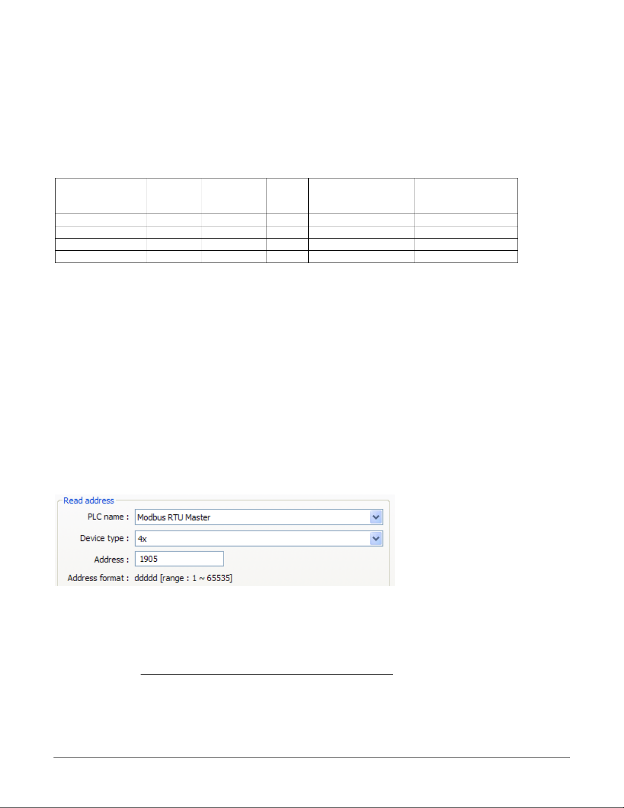
EasyBuilder5000’s Modbus drivers call the data block, “Device type” and for “Address” expect the
memory location’s absolute address without the data block number. For example, to access a value in a
holding register with absolute address 401,905, for Device type you select the data block “4x” and enter
“1905” in the Address field. The following illustrates setting this address in EasyBuilder5000.
(072)
Watlow controllers use only the 4x registers. Therefore, you will set the Device type to 4x to access any
parameter in a Watlow controller. Watlow manuals specify relative addresses. Therefore, you must add
one (1) to an address found in a Watlow manual (other than this one) before you enter it in
EasyBuilder5000.
For example, the EZ-ZONE PM Controller Communications Manual
lists the relative address for Heat
Power as 1904. To monitor the heat power with the Silver Series OIT, you will add one (1) to the
relative address and enter “1905” in the Address field in EasyBuilder5000.
Silver Series OIT 5 Watlow Addendum
Page 6

(073)
In summary, when setting an address for a screen object to read or write from a Watlow controller:
For the Device type select 4x.
Set the Address to a value that is one greater than the relative Modbus address listed in the
Watlow manual.
Choosing the Communications Drivers
When you create a project using EasyBuilder5000 you select the drivers necessary to communicate with
the Watlow controllers and any other devices with which the Silver Series OIT must communicate. For
Watlow controllers, you select one of these drivers:
Modbus RTU Master—used with Watlow controllers that support Modbus RTU and communicate
via RS-232 or RS-485.
Modbus TCP/IP Master—used with Watlow controllers that support Modbus TCP and
communicate via Ethernet.
When you set up the Silver Series OIT to communicate via 485, you add a Modbus RTU Master device
to the device list in the System Parameter Settings. Only one driver is required for each COM port on the
OIT to which controllers are connected. This is regardless of the number of controllers that are
connected to that 485 COM port. Think of the Modbus RTU Master device as a driver for the COM port
not as a driver for the controllers themselves. That is why you choose the Modbus RTU Master driver
rather than the Modbus RTU Slave driver. The controllers are slaves; the OIT’s COM port is the master.
When you set up the OIT to communicate via a 232 COM port, you add a Modbus RTU Master device
to the device list in the System Parameter Settings. When using 232 on a COM port, only one controller
can be connected to that port.
When you set up the OIT to communicate with controllers via Ethernet, you add one Modbus TCP/IP
Master device to the device list in the System Parameter Settings dialog for each controller that has an
IP address with which you will communicate. For example, if the OIT must communicate with three EZZONE controllers via Ethernet, add three Modbus TCP/IP Master devices to the device list in the
System Parameter Settings dialog each configured to communicate with one controller.
Addressing Parameters in Multiple Controllers
Normally the Silver Series OIT assumes that any register address you enter is associated with the
controller at the network address you set in the PLC default station no field in the Device Properties
under the System Parameter Settings.
Silver Series OIT 6 Watlow Addendum
Page 7
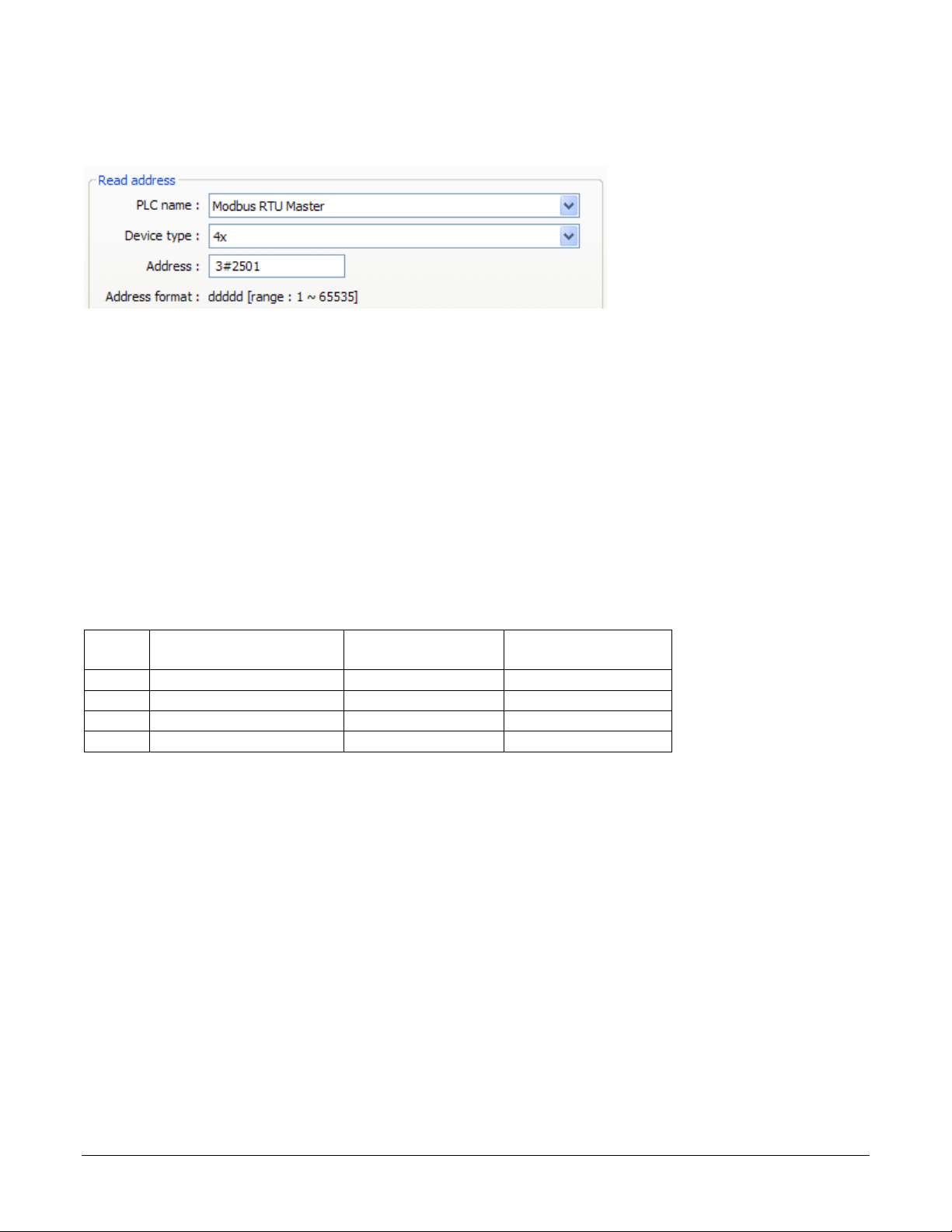
To read or write data from a register in another controller on the 485 network, enter the network address
and register address separated by the number sign (#). For example “3#2501” accesses register 2501 in
the controller with the Modbus network address 3.
(074)
Address Offsets in Multi-Loop Controllers
In controllers with more than one loop of control, more than one limit etc., there is more than one
instance of each parameter for these duplicated functions. The manual for controllers such as the EZZONE RM, lists the Modbus address and an offset for these parameters. Add the offset to the address
once to get the address of the second instance of the parameter, add it twice to get the third instance and
so on.
For example, the address of the Heat Power for Loop 1 is listed in the EZ-ZONE RM manual as 2244
with an offset of 70. The following table lists the addresses of the Heat Power parameter for each of the
four possible loops in the controller. The table also reminds you to add one (1) to the relative addresses
from the controller manuals before entering the parameter address in EasyBuilder5000.
Loop Address + Offset(s)
1 2224 2224 + 1 2225
2 2224 + 70 2294 + 1 2295
3 2224 + 70 + 70 2364 + 1 2365
4 2224 + 70 + 70 + 70 2434 + 1 2435
Convert Relative
Address
Enter in
EasyBuilder5000
Accessing Parameters via EZ-ZONE RUI Gateways and RM Access Modules
Multiple EZ-ZONE devices can communicate with the Silver Series OIT via one or more EZ-ZONE
RUI Gateways or EZ-ZONE RM Access modules. When ordered with either the Modbus TCP or
Modbus RTU communications option an RUI Gateway or RM Access module allows a Silver Series
OIT to communicate with one or more EZ-ZONE controllers without purchasing the Modbus
communications option in each controller.
In such a system the Silver Series OIT is connected to and configured to communicate with the gateway.
The gateway presents itself as a single device on the Modbus network; the OIT does not communicate
with the controllers, only with the gateway. The gateway is configured by the user with an address offset
for each controller connected to it. That address offset is added to the parameter addresses for the
controller.
Silver Series OIT 7 Watlow Addendum
Page 8

For example, consider three EZ-ZONE PM controllers connected to an RUI Gateway configured with an
offset of 0 for the first controller, 5000 for the second controller and 10,000 for the third controller. The
table below indicates the addresses that must be entered in EasyBuilder5000 to access the set point value
in the three PM controllers.
PM Set Point Plus Gateway Offset
1 2172 2172 + 0 2172 + 1 2173
2 2172 2172 + 5000 7172 + 1 7173
3 2172 2172 + 10000 12172 + 1 12173
Convert Relative
Address
Enter in
EasyBuilder5000
Data Types
The Silver Series OIT’s Modbus drivers support a variety of data types. The Watlow manuals specify
the data type of each parameter. However the terminology is not precisely the same. The table below
correlates the data types indicated in the Watlow manuals with the data types you should select when
configuring a screen object in EasyBuilder5000.
EZ-ZONE RM EZ-ZONE ST EZ-ZONE PM EasyBuilder5000
Int Unsigned uint 16-bit Unsigned
dint 32-bit Signed
Float IEEE Float float 32-bit Float
Important Things to Know
Note: Make sure the controller’s Modbus Word Order is set to Word Low High in the
controller. That is the setting that works with the Silver Series OIT.
Note: Examples in this manual use the map 1 addresses. Make sure the controller’s
Data Map is set to 1.
Caution: When you use a multi-state switch object to set an enumerated parameter in a
controller, each time the user clicks the switch, the setting selected by the switch
is sent to the controller. When it is desirable to go directly from one setting to
another without intermediate settings, use a set word object or an option list to
set the parameter instead.
Silver Series OIT 8 Watlow Addendum
Page 9
Chapter 4: Programming
4
Tutorials
The following sections guide you through creating a first project using EasyBuilder5000 and a Silver
Series OIT that communicates with a Watlow controller.
Create a First Project
The following procedure guides you through the process of configuring a Silver Series OIT to
communicate with a Watlow Controller.
1) To launch
EasyBuilder5000:
on the Windows
task bar click
Start, click All
Programs, click
Watlow, click
EZware-5000 and
click EasyBuilder
5000.
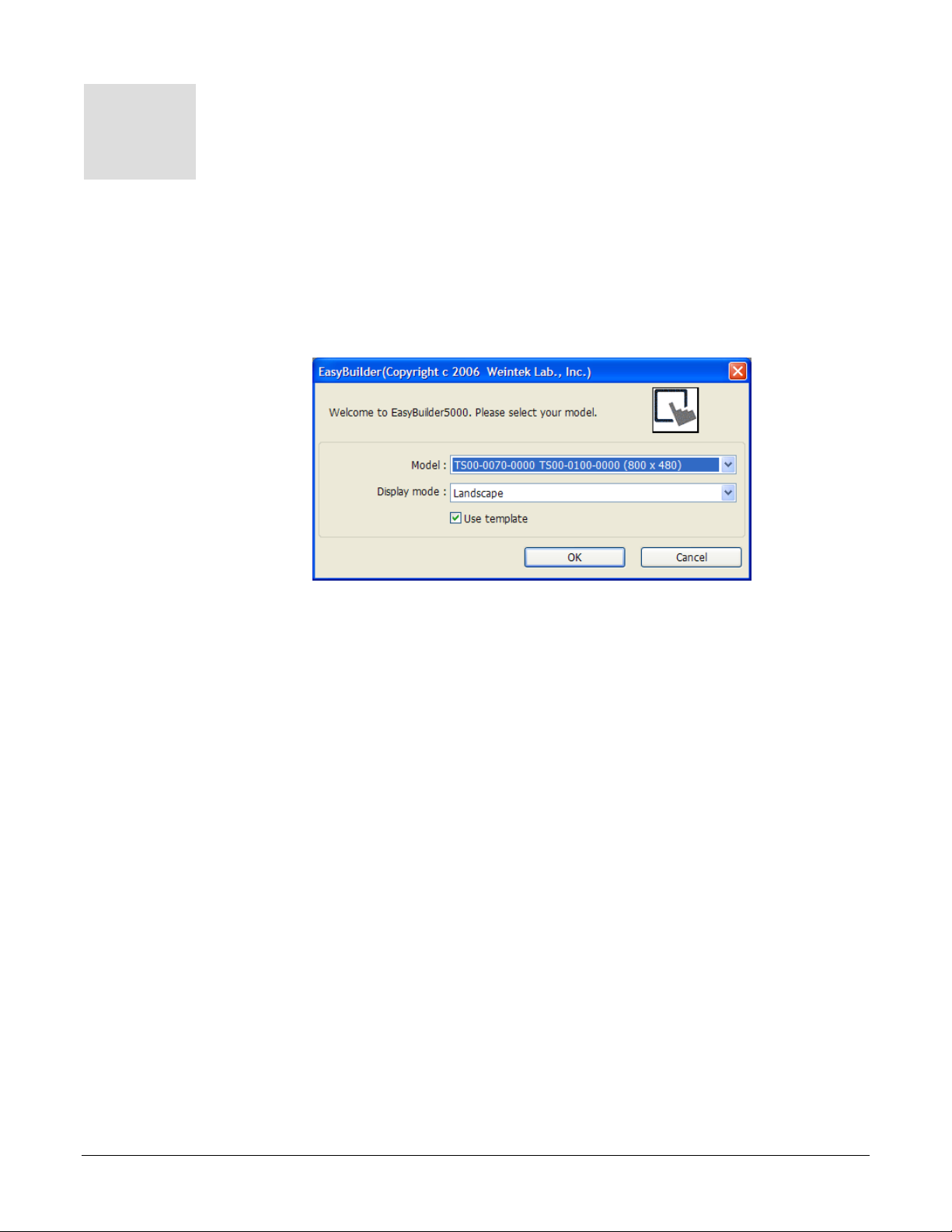
2) In the Welcome to
EasyBuilder5000
dialog, for Model,
choose the OIT
model you have.
3) Click OK.
Note: If you have previously created a project, that project will open. In
that case from the File menu, choose New to create a blank project for
this tutorial and to see the Welcome dialog.
Note: The TS00-0070-0000 and TS00-0100-0000 are supported by the
same driver.
Note: Only Landscape Display mode is available for the TS00-00700000 and TS00-0100-0000 models.
(001)
Silver Series OIT 9 Watlow Addendum
Page 10
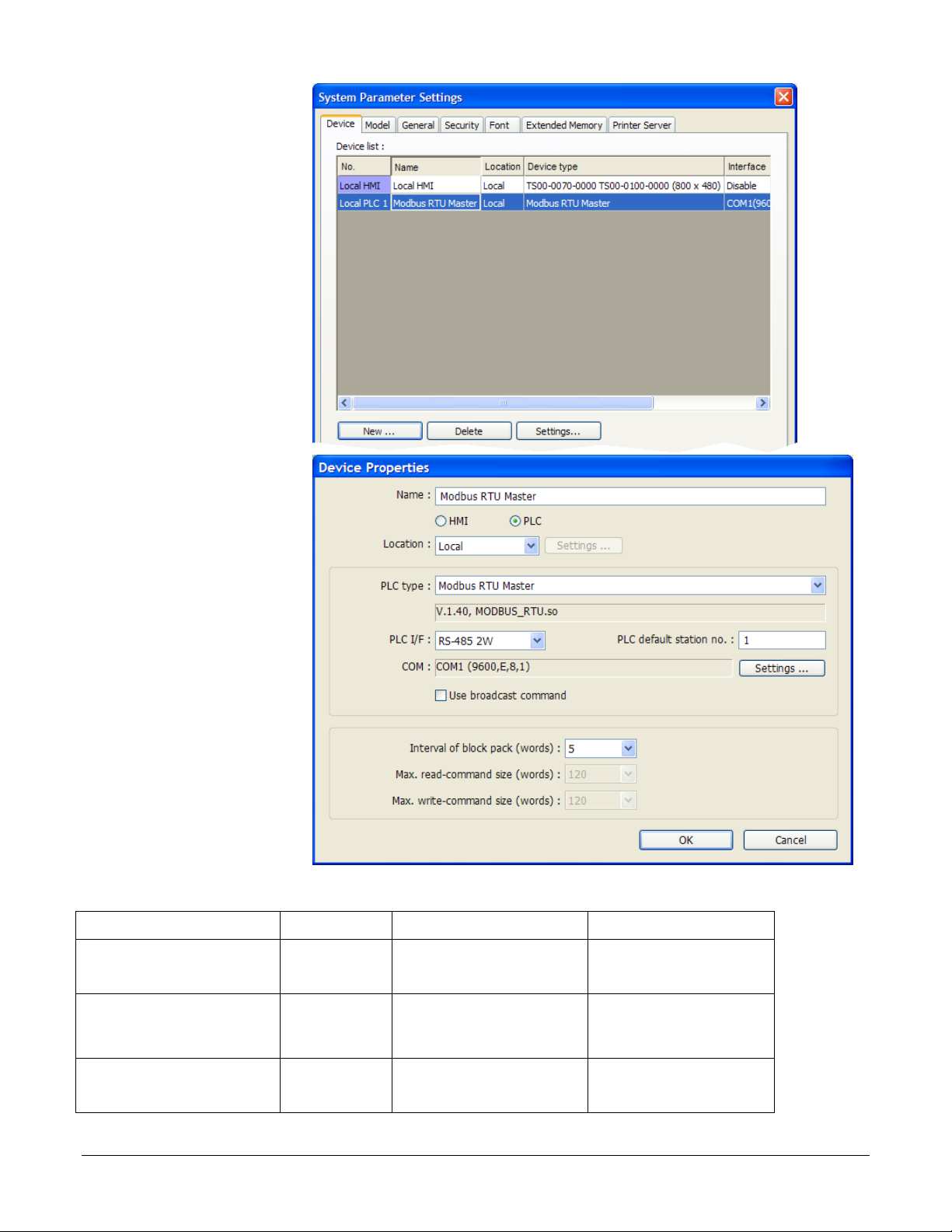
4) In the System
Parameter
Settings dialog, in
the Device List,
select the Local
PLC 1 device and
click Settings…
5) For PLC type,
choose the
appropriate driver.
See the table
below.
(002)
6) For PLC I/F,
choose the
appropriate
hardware interface.
See the table
below.
7) For PLC default
station no. type
the controller’s
address. Typically
this is 1 for the
first controller.
8) Click Settings…
For part numbers like… with… For PLC type choose… For PLC I/F choose…
STxx-xxx-xxxx
PMxxxxx-1xxxxxx
RMCxxxx-xxxx1xx
PMxxxxx-2xxxxxx
EZKx-2xxx-xxxx
RMAx-x2xx-xxxx
PMxxxxx-3xxxxxx
EZKx-3xxx-xxxx
RMAx-x3xx-xxxx
(003)
Modbus RTU Modbus RTU Master RS-485 2W
Modbus RTU Modbus RTU Master RS-232 or RS-485 2W*
Modbus TCP Modbus TCP/IP Master Ethernet
Silver Series OIT 10 Watlow Addendum
Page 11
For part numbers like… with… For PLC type choose… For PLC I/F choose…
Other Watlow Controllers Modbus RTU Modbus RTU Master RS-232 or RS-485 2W*
*Both 232 and 485 are available; choose the one to which you have connected the OIT.
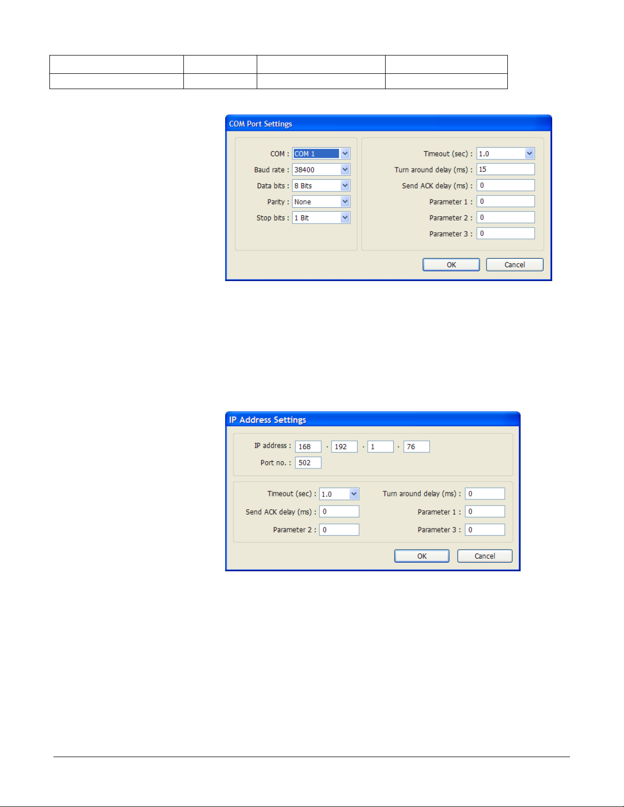
9) If you set PLC I/F to
RS-232 or RS-485
2W…
For COM, choose the
communications port to
which you have
connected the
controller. Typically
this is COM 1.
For Baud rate, choose
the rate that is set in the
(004)
controller.
For Data bits, choose 8 Bits.
For Parity, choose None.
For Stop bits, choose 1 Bit.
For multiple controllers on the same port, for Turn around delay (ms), enter 15.
Click OK.
10) If you set PLC I/F to
Ethernet…
For IP address, enter
the IP address of the
controller.
Click OK.
11) Click OK to close the
Device Properties
dialog.
12) To set up communications with controllers connected to other COM ports or to configure
additional controllers communicating via Ethernet:
Click New...
Repeat from step 4 above.
13) Click OK to close the System Parameter Settings dialog.
(005)
14) Save the project:
From the File menu, choose Save.
Silver Series OIT 11 Watlow Addendum
Page 12
In File name type First Project.mtp.
Click Save.
Create a Popup Window
This example assumes you have created a project that configured to communicate with a Watlow
controller and that project is open in EasyBuilder5000.
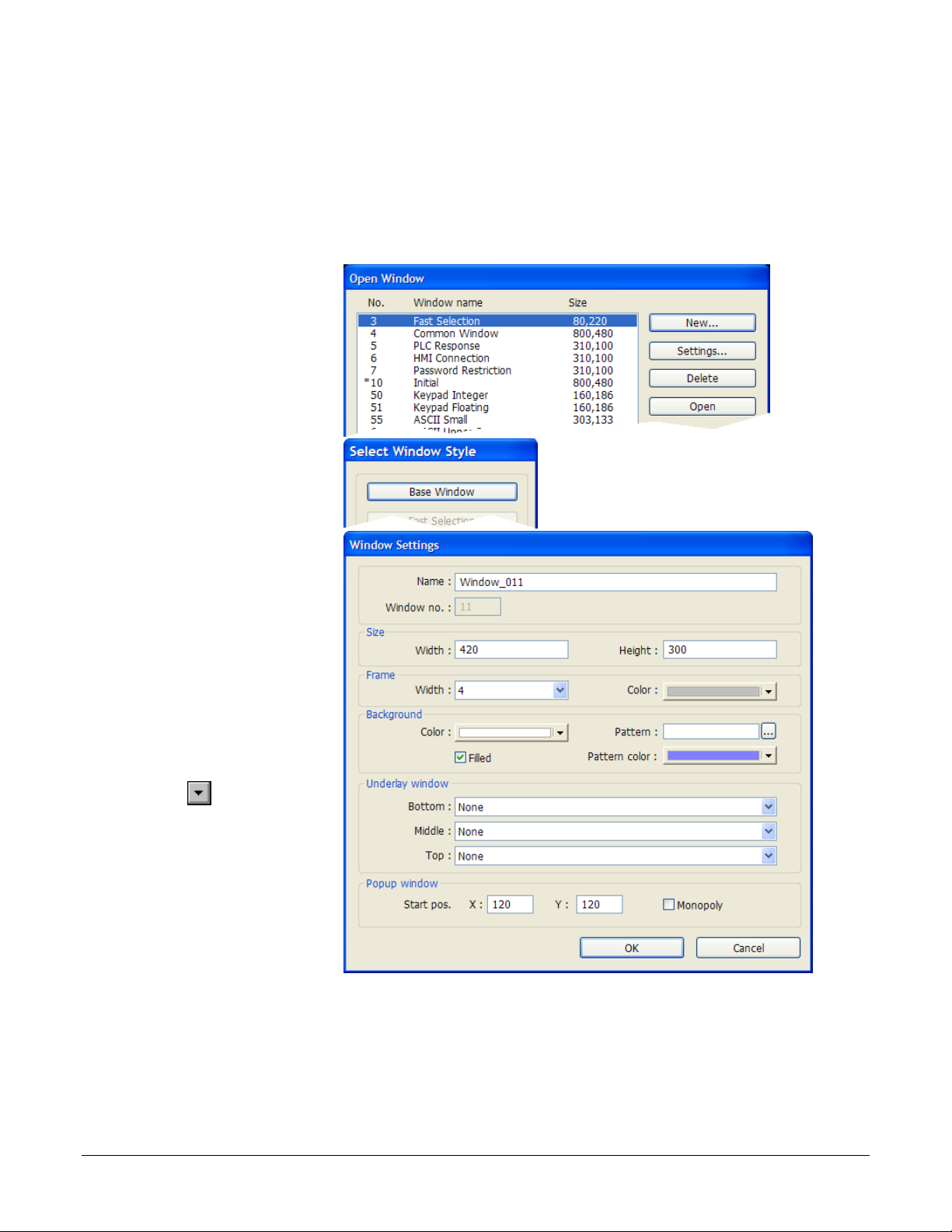
1) From the Window
menu, choose Open
Window.
2) Click New…
(006)
3) Click Base Window.
(007)
4) Ensure the Name is
Window_011 and the
Window no. is 11.
5) Set Width to 420.
6) Set Height to 300.
7) To set the background
color to white:
In the Background
group, next to Color
click
.
Select the white color
swatch in the Basic
colors group.
Click OK.
8) In the Popup window group, set Start pos. X to 120.
9) In the Popup window group, set Start pos. Y to 120.
10) Click OK.
(008)
11) In the Open Window dialog, select Window_11.
Silver Series OIT 12 Watlow Addendum
Page 13
12) Click Open.
13) From the File menu choose Save.
Create a Meter in a Popup Window
This example assumes you have created a popup window in a project that is configured to communicate
with a Watlow Controller and that window is open in EasyBuilder5000.
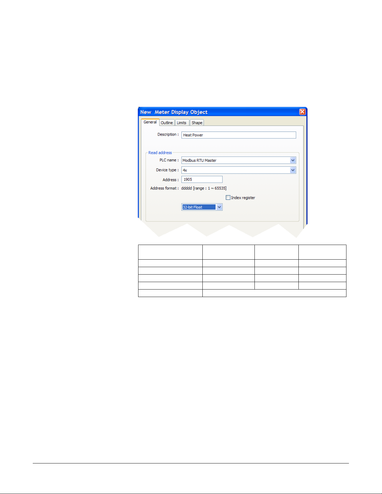
1) From the Objects
menu, choose Meter
Display.
2) Click the General tab.
3) In Description type
Heat Power.
4) For PLC name choose
Modbus RTU Master
or Modbus TCP/IP
Master.
5) For Device type
choose 4x.
6) For Address enter the
address of the
parameter to be
displayed on the meter.
See the table for the
addresses of the Heat
Power.
7) Select the data type for
the parameter to be
displayed in the field
below the Address
field. See the table.
For this
controller…
RMCxxxx-xxxxxxx Heat Power 2245 32-bit Float
PMxxxxx-xxxxxxx Heat Power 1905 32-bit Float
STxx-xxMx-xxxx Heat Power 237 32-bit Float
ST via RUI Gateway Heat Power 1901 32-bit Float
Other Controllers* Consult the controller manual.
*These addresses have already been changed to the absolute form
required for EasyBuilder5000 by adding 1 to the value listed in the Watlow
manual. Enter them as listed
This
parameter…
Enter this
Address*…
(009)
Choose this
Data Type…
Silver Series OIT 13 Watlow Addendum
Page 14
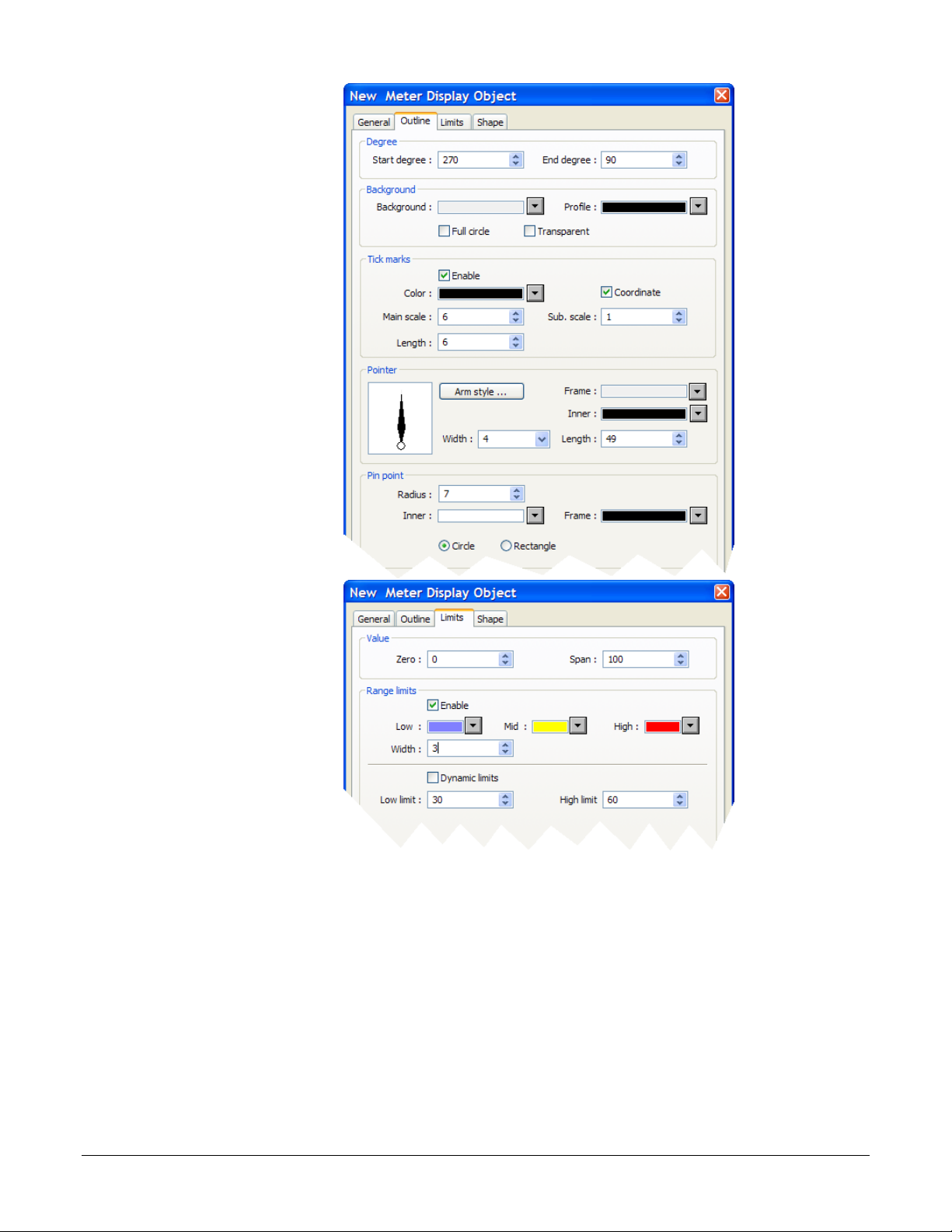
8) Click the Outline tab.
9) In Degree set Start
degree to 270.
10) In Degree set End
degree to 90.
11) In Background
uncheck Full circle.
12) In Tick marks check
Enable.
13) For Tick marks
Color, select black.
14) In Tick marks set
Main scale to 6.
15) In Tick marks set Sub
scale to 1.
16) In Tick marks set
Length to 6.
17) Click the Limits tab.
(010)
18) Set Value Zero to 0.
19) Set Value Span to
100.
20) Check Range limits
Enable.
21) Set Width to 3.
(011)
22) Click OK.
23) Move the cursor with the outline of the meter to position it and click to place the meter in
Window_11.
24) Resize the meter with the corner handles to make it smaller, if necessary
Silver Series OIT 14 Watlow Addendum
Page 15

25) Double-click the meter
to open the Meter
Display Object’s
Properties dialog.
26) Click the Profile tab.
27) Set X to 140.
(012)
28) Set Y to 60.
29) Set Width to 140.
30) Set Height to 140.
31) Click OK.
32) From the File menu
choose Save.
Add a Numeric Display
This example assumes you have created a window in a project that is configured to communicate with a
Watlow Controller and that window is open in EasyBuilder5000.
1) On the Objects menu,
click Numeric/ASCII
then choose Numeric
Display.
2) Click the General tab.
3) In Description type
Numeric Display.
4) For PLC name choose
Modbus RTU Master
or Modbus TCP/IP
Master.
5) For Device type
choose 4x.
(013)
Silver Series OIT 15 Watlow Addendum
Page 16

6) For Address enter the
address of the
parameter to be
displayed on the meter.
See the table below for
the addresses of the
Closed Loop
Working/Active Set
Point.
7) Click the Numeric
Format tab.
8) In Data format set the
data type for the
parameter to be
displayed.
9) On the Font tab set
Align to Right.
10) Click OK.
(013)
For this
controller…
RMCxxxx-xxxxxxx 2513 32-bit Float
PMxxxxx-xxxxxxx 2173 32-bit Float
STxx-xxMx-xxxx 204 32-bit Float
ST via RUI Gateway
Other Controllers* Consult the controller manual.
*These addresses have already been changed to the absolute form required
for EasyBuilder5000 by adding 1 to the value listed in the Watlow manual.
Enter them as listed.
This
parameter…
Closed Loop
Working/Active
Set Point
(Read Only)
Enter this
Address*…
2173 32-bit Float
Choose this
Data Type…
11) Move the cursor with
the outline to position
the display field and
click to place it.
12) Adjust the size of the
field as needed.
13) From the File menu
choose Save.
(014)
Silver Series OIT 16 Watlow Addendum
Page 17

Add Increment and Decrement Buttons
This example assumes you have created a window in a project that is configured to communicate with a
Watlow Controller and that window is open in EasyBuilder5000.
To add a button that increments the set point:
1) On the Objects menu,
click Button then
choose Set Word.
2) Click the General tab.
3) In Description type
Increment Set Point.
4) For PLC name choose
Modbus RTU Master
or Modbus TCP/IP
Master.
5) For Device type
choose 4x.
6) For Address enter the
address of the
parameter to be
displayed on the meter.
See the table for the
addresses of the User
Set Point.
7) Select the data type for
the parameter to be
displayed in the field
below the Address
field.
8) In Attribute for Set
Style choose Press and
hold increment
(JOG++).
For this controller…
RMCxxxx-xxxxxxx 2501 32-bit Float
PMxxxxx-xxxxxxx 2161 32-bit Float
STxx-xxMx-xxxx 22 32-bit Float
ST via RUI Gateway
Other Controllers* Consult the controller manual.
*These addresses have already been changed to the absolute form required
for EasyBuilder5000 by adding 1 to the value listed in the Watlow manual.
Enter them as listed.
This
parameter…
User Set Point
(Read/Write)
Enter this
Address*…
2161 32-bit Float
(015)
Choose this
Data Type…
9) Set Inc. value to 1.
10) Set Upper Limit to 100 or a value that is safe for your controller’s set point.
11) Set JOG delay to 0.5 seconds.
12) Click the Shape tab.
13) Check Use shape.
Silver Series OIT 17 Watlow Addendum
Page 18

14) Click Shape
Library…
15) Click Select Lib…
16) Select Arrows 1.plb.
17) Click Open.
18) Locate the button with
the triangular arrow
pointing up and click
it.
19) Click OK to close the
Shape Library.
20) Click OK to close the
New Set Word Object
dialog.
21) Click to place the
button.
(016)
22) Use the handles to
adjust the size of the
button.
23) Drag the button to
place it as desired on
the screen.
24) From the File menu
choose Save.
(017)
Silver Series OIT 18 Watlow Addendum
Page 19

To add a button that decrements the set point:
1) Click the increment
button to select it.
2) From the Edit menu,
choose Copy.
3) From the Edit menu,
choose Paste.
4) Drag the new button to
an appropriate
position.
5) Deselect the button by
clicking on the
window’s background
or another item in the
window.
(018)
6) Double click the new button to edit its properties.
7) On the General tab change:
Description to Decrement Set Point
Set Style to Press and hold decrement (JOG--).
8) Set Bottom Limit to 0.
9) On the Shape tab click Shape Library…
10) Locate the button with the triangular arrow pointing down and click it.
11) Click OK to close the Shape Library.
12) Click OK to close the Set Word Object Properties dialog.
13) From the File menu choose Save.
Silver Series OIT 19 Watlow Addendum
Page 20

Add an Option List for Control Mode
This example assumes you have created a window in a project that communicates with a Watlow
Controller and that window is open in EasyBuilder5000.
1) On the Objects menu,
click Button then
choose Option List.
2) Click the General tab.
3) In Description type
Control Mode.
4) Set Mode to Drop-
down list.
5) Set No. of states to 3.
6) In the Control address
group:
For PLC name choose
Modbus RTU Master or
Modbus TCP/IP
Master.
For Device type choose
4x.
In Address enter the
address of the Control
Mode. See the table.
Select the data type for
the parameter in the
field below the
Address field.
For this controller…
RMCxxxx-xxxxxxx 2221 16-bit Unsigned
PMxxxxx-xxxxxxx 1881 16-bit Unsigned
STxx-xxMx-xxxx 222 16-bit Unsigned
ST via RUI Gateway
Other Controllers* Consult the controller manual.
*These addresses have already been changed to the absolute form required
for EasyBuilder5000 by adding 1 to the value listed in the Watlow manual.
Enter them as listed.
This
parameter…
Control Mode
Enter this
Address*…
1881 16-bit Unsigned
(019)
Choose this
Data Type…
7) Click the Mapping
tab.
Silver Series OIT 20 Watlow Addendum
Page 21

8) In the Values column
type the numeric and
text values that
corresponds to each
option you want to
include. See the table.
9) Click OK to close the
New Option List
Object dialog.
10) Position the cursor
near the bottom center
of the window layout
and click to place the
multi-state switch.
(You may have to
move the other objects
around to fit
everything.)
State Value Enumerated Value
0 10 Auto
1 54 Manual
2 62 Off
3 (error)
(020)
11) From the File menu
choose Save.
(022)
Silver Series OIT 21 Watlow Addendum
Page 22

Add a Button to Close the Popup Window
This example assumes you have created a window in a project that communicates with a Watlow
Controller and that window is open in EasyBuilder5000.
1) On the Objects menu,
click Button then
choose Function Key.
2) On the General tab, in
Description type Close
Window.
3) Select Close window.
4) On the Shape tab,
uncheck Use shape.
5) Check Use picture.
6) Click Picture
Library…
7) Click Select Lib…
(023)
8) Select Computer.flb.
9) Click Open.
10) Locate the circular
grey button with the
white x and click to
select it.
11) Click OK to close the
Picture Library.
12) On the Label tab,
make sure Use label is
not checked.
(024)
13) Click OK to close the New Function Key Object dialog.
14) Click to place the function key in the upper right.
15) Double-click the function key to open the Function Key Object’s Properties dialog.
Silver Series OIT 22 Watlow Addendum
Page 23

16) Click the Profile tab
17) Set Position X to 375.
18) Set Position Y to 5.
19) Set Size Width to 40.
20) Set Size Height to 40.
21) Click OK.
22) From the File menu
choose Save.
(025)
Edit the Startup Window
This example assumes you have created a popup window open in EasyBuilder5000 in a project that is
configured to communicate with a Watlow Controller.
To add text to the start up window:
1) From the Window
menu, choose 1 10 –
Initial.
2) From the Draw menu
choose Text.
3) Set these text
Attributes:
Choose a Font.
Set Color to white.
Set Size to 14.
Set Align to Left.
4) Edit Content to read,
This is the Startup
Screen.
5) Click OK.
(026)
Silver Series OIT 23 Watlow Addendum
Page 24

6) Position the cursor centered in the top third of the window layout and click to place the text.
7) From the File menu choose Save.
Add a Numeric Display to the main window:
1) On the Objects menu,
click Numeric/ASCII
and choose Numeric
Display.
2) Click the General tab.
3) In Description type
Process Variable.
(027)
4) For PLC name choose
Modbus RTU Master
or Modbus TCP/IP
Master.
5) For Device type
choose 4x.
6) For Address enter the
address of the Analog
Input 1 Process Value.
See the table.
7) Click the Numeric
Format tab.
8) In Data format set the
data type for the
parameter to be
displayed.
9) Set Right of decimal
Pt. to 1.
For this controller…
RMCxxxx-xxxxxxx 361 32-bit Float
PMxxxxx-xxxxxxx 361 32-bit Float
STxx-xxMx-xxxx 20 32-bit Float
ST via RUI Gateway
Other Controllers* Consult the controller manual.
*These addresses have already been changed to the absolute form required
for EasyBuilder5000 by adding 1 to the value listed in the Watlow manual.
Enter them as listed.
This
parameter…
Analog Input 1
Process Value
Enter this
Address*…
361 32-bit Float
Choose this
Data Type…
(028)
10) On the Font tab set
Align to Right.
11) Click OK.
(029)
Silver Series OIT 24 Watlow Addendum
Page 25

12) Move the cursor with
the outline to position
the display field in the
center of the screen
and click to place it.
13) From the File menu
choose Save.
To create a function key on Window10:
1) On the Objects menu,
click Button then
choose Function Key.
2) On the General tab, in
Description type Loop
1 Settings.
3) Select Display popup
window.
4) For Window no. select
11. Window_011.
(030)
(031)
5) Click the Shape tab.
6) Check Use shape.
7) Click Shape Library…
8) In the Library list select Buttons 1.
9) Click one of the buttons to select it.
10) Click OK to close the Shape Library.
11) Click the Label tab.
12) Check Use label.
13) Set Color to black.
14) Set Size to 16.
15) Set Align to Left.
16) In Content type Loop 1.
17) Click OK.
Silver Series OIT 25 Watlow Addendum
Page 26

18) Position the cursor and
click to place the
function key.
19) From the File menu
choose Save.
Compile and Download the Project
This example assumes you have a project that is ready to compile and load into an OIT.
To compile the project:
1) From the Tools menu,
choose Compile.
(032)
2) Click Compile.
3) After the project is
compiled, click Close.
(034)
To download via Ethernet or via a USB cable:
1) If downloading via Ethernet, determine the OIT’s IP address:
Connect a USB mouse to the OIT.
Apply power to the OIT.
Once the OIT is powered up, move the mouse pointer to the lower right corner of the OIT
screen.
If a button with an arrow “<” appears click it.
On the menu bar click the setting button (the one with the wench icon).
Silver Series OIT 26 Watlow Addendum
Page 27

Enter the password. (By default this is 111111.)
Minimize the Virtual Keyboard window.
Note the IP address listed in the System settings window on the Network tab. (If Auto Get IP
Address is selected, the IP Address is not editable. If you configure the OIT for a fixed address
by selecting IP address get from below, then you can enter the IP address here.
Click OK to close the System settings window on the OIT.
2) If downloading via a USB cable:
Connect the USB cable to the OIT.
Apply power to the OIT.
Connect the USB cable to a USB port on the computer.
If this is the first time you have connected the OIT to the computer via the USB port, locate a
follow the procedure in the EasyBuilder 5000 help, “How Do I Install the Maple Systems USB
driver?”
3) In EasyBuilder5000
from the Tools menu,
choose Download.
4) Select Ethernet or
USB cable.
5) For Ethernet, in HMI
IP select or enter the
OITs IP address.
6) Set Password to the
OITs password
(111111 by default).
7) Check Firmware, if
not already checked.
8) Check Reboot HMI
after download, if not
already checked.
9) Click Download.
(035)
10) Once the download is complete, click Exit.
Silver Series OIT 27 Watlow Addendum
Page 28

To download the project from EasyBuilder5000 to a USB drive:
1) Connect at USB drive to the PC
2) From the Tools menu
choose Build Data for
USB Disk or CF Card
Download…
(038)
3) Click Browse…
4) Locate and select the
USB drive.
Note: Do not select a sub
directory of the USB drive.
Select the root.
5) Click OK to close the
Browse For Folder
dialog.
6) Click Build.
7) When the files are transferred successfully, click OK.
8) Click Exit to close the USB Disk/CF Card Data dialog.
(039)
9) Remove the USB drive from the PC.
To download the from the USB drive to the OIT:
1) Connect a USB mouse to the OIT.
2) Apply power to the OIT.
3) Once the OIT is powered up, connect the USB drive to it.
4) When the download/Upload screen appears on the OIT click Download.
Note: You only have a few seconds to do this before the screen times out. If you miss it, disconnect the
USB drive and connect it again.
5) With the Virtual Keyboard enter the Password. (By default this is 111111.)
Note: If you have difficulty entering the password, see the hints below.
6) On the Download Settings dialog make sure Download Project Files is checked.
Silver Series OIT 28 Watlow Addendum
Page 29

7) Click OK.
8) In the Pick a Directory dialog expand the usbdisk folder by clicking the plus (+) next to it.
9) Select the folder that represents the USB drive in the usbdisk folder.
Note: The OIT represents the USB drive with a folder icon and a name it assigns such as disk_a_1. You
can inspect the contents to be sure you pick the right one. The compiled project is in a directory
called mt8000, but be sure to select the USB drive not a sub folder before proceeding.
10) Click OK.
11) Once the project downloads and runs, you can remove the USB drive from the OIT.
Hints for using the Virtual Keyboard to enter the OIT password:
If you do not see the Virtual Keyboard it may be minimized. Move the mouse to the bottom of
the screen and click the X on the menu bar.
Make sure the cursor is in the Password field on the Download Settings dialog.
Enter the password by clicking only the keys on the Virtual keyboard without first clicking
anywhere else.
You can tell the password key strokes are being entered if you hear the key chirp from the OIT
and see stars (******) appearing in the password field.
If you cannot see the Password field, arrange the Virtual Keyboard and Download.
If you are entering the password on the Virtual Keyboard but stars aren’t appearing in the
Password field, make sure the Password field has focus. If you do not see the text insertion
cursor ( | ) in the Password field, it does not have focus. Click in the Password field to give it
focus then click keys, but nothing else on the Virtual Keyboard.
One you have entered the password and the stars appear in the Password field, you can
minimize the Virtual Keyboard by clicking the minimize button at the upper right corner to
access the check boxes and buttons on the Download Settings dialog.
Log Data
This example assumes you have a project with at least one controller.
There are two steps to log data with the OIT:
Copy data from the controller to contiguous local OIT memory with the Data Transfer (Time-
based) object—this is necessary only if you want to log more than one parameter in the same
file or show multiple parameters together in a Trend Display (graph) or a History Data Display
(table).
Create a data log with the Data Sampling object.
Note: This example uses specific addresses internal to the OIT. If you have used one or more of these
for other purposes you will have to choose appropriate addresses for your project.
Silver Series OIT 29 Watlow Addendum
Page 30

To copy data to the OIT’s local memory:
1) From the Objects
menu choose Data
Transfer (Timebased).
2) For each item to be
logged in the file:
Click New…
For Address type
choose Word.
In Description type a
description of the data
to be copied such as
“PV 1”.
For Interval choose a
value that is the same
as or less than the
amount of time you
want between data
samples.
(041)
In No. of words type
word size of the
parameter’s data type.
See table.
For Source address
PLC name choose
Modbus RTU Master or
Modbus TCP/IP
Master.
(042)
For Source address
Device type choose 4x.
Data Type No. of words
Float 2
16-bit integer 1
32-bit integer 2
In Source address Address type the address of the parameter to be logged.
For Destination address PLC name choose the OIT (“Local HMI” by default).
For Destination address Device type choose LW.
In Destination address Address type the local address at which to save the data to be logged.
Note: Pick a range of addresses with room to store all the data that must be displayed. For example, use
200 for the first parameter to be logged then for each additional parameter increment the address by
Silver Series OIT 30 Watlow Addendum
Page 31

the size in words of the previous data. For example, typically you log floats such as process
variables and set points which each require two words to store. In that case if the first process
variable is copied to 200, set the next parameter to copy to 202 so on. In this example, a process
variable, a set point and the heat output power are logged.
Click OK.
3) Click Exit to close the
Data Transfer (Timebased) Object window.
To set up data sampling to log the data:
1) From the Objects
menu choose Data
Sampling.
(043)
2) Click New…
(044)
Silver Series OIT 31 Watlow Addendum
Page 32

3) In Description type a
description for the set
of data such as “Loop
1”.
4) For Sampling mode
choose Time-based.
5) For Sampling time
interval choose the
time between samples.
6) For Read address
PLC name choose the
OIT (“Local HMI” by
default).
7) For Read address
Device type choose
LW.
8) In Read address
Address type the first
address to which data
was copied. In the
example, this is 200.
(045)
9) In Max. data records type the number of records to save in a file.
10) Click Data Format…
11) For each item to be
logged in the file:
Click New…
Enter a description for
the item to be logged,
for example “PV 1”.
For Data type choose
the data type of the
item being logged.
Typically 32-bit Float).
Click OK.
(046)
(047)
Silver Series OIT 32 Watlow Addendum
Page 33

12) Click Exit to close the
Data Format window.
13) Check one or more
locations to which to
save the data (Save to
USB 1 or Save to
HMI memory).
14) In Folder name type a
name for the folder in
which the data log file
should be created such
as “datalog”.
15) Click OK to close the
Data Sampling
Object set up window.
(048)
(049)
16) Click Exit to close the
Data Sampling
Object window.
(050)
Create a Graph
This example assumes you have a project with at least one controller and that you have previously
configured a time-based data sampling object.
To create and open a window to use for the trend.
1) From the Window
menu, choose Open
Window.
2) Click New…
(056)
Silver Series OIT 33 Watlow Addendum
Page 34

3) Click Base Window.
(007)
4) In Name type Trend.
5) Click OK.
6) In the Window list
select Trend.
7) Click Open.
To create buttons to open the Trend window and return to the first window:
1) Select window 10.
(057)
(064)
2) Select the function
key on that screen by
clicking it once.
(065)
3) From the Edit menu, choose Copy.
4) From the Edit menu, choose Paste.
5) Place the copy next to the original.
6) Click on the screen background to deselect the button.
7) Double-click the copy to open the Function Key Object’s Properties window.
8) Edit the Description
to read Trend Graph
Window.
9) Choose Change full-
screen window.
10) For Window no.
choose 12. Trend.
(066)
11) Click the Label tab.
12) Edit the Content to read Trend.
13) Click OK to close the Function Key Object’s Properties window.
14) Select the function key on that screen by clicking it once.
Silver Series OIT 34 Watlow Addendum
Page 35

15) From the Edit menu, choose Copy.
16) Select window 12 Trend.
17) From the Edit menu, choose Paste.
18) Position the button centered at the bottom of the screen.
19) Edit the new button’s properties so that it changes to full-screen window 10 Initial and is
labeled “Back”.
To create a trend graph:
1) From the Objects
menu choose Trend
Display.
2) In Description type a
description of the trend
such as “Loop 1 PV,
SP and Heat vs. Time”.
3) For Data Sampling
Object index choose
the data sampling
(051)
object you previously
configured.
4) For Trend type choose Real-time.
5) For No. of channels choose the number of items you want to graph from the data sampling
object.
6) For X axis time range choose Time.
7) In Distance type the number of seconds the width of the trend graph will represent. For
example, if you want to see two minutes of data at once, type 120.
Silver Series OIT 35 Watlow Addendum
Page 36

8) Click the Trend tab.
9) Choose a Frame color
and a Background
color.
10) In the Channel group
for each item to be
graphed:
For Channel choose the
channel to be
configured.
For Color choose a
color that contrasts with
the background color.
In Zero type the value
that should be graphed
at the bottom of the yaxis.
In Span type the value
that should be graphed
at the top of the y-axis.
(052)
Note: Think of channels as the pens on a multi-pen chart recorder.
Channels are numbered starting at 0. Start with 0 and configure each.
Note: Keep in mind that while you can choose a different zero and
span for each pen, you don’t want to confuse users, so it may be best
to graph all the channels against the same zero an span values.
11) Click OK.
12) Place and size the trend
object.
(053)
Silver Series OIT 36 Watlow Addendum
Page 37

13) Optional: In the Trend
Display Object
Properties dialog
Trend tab enable the
Grid and set it up to
display the time.
14) Optional: Use the
Scale tool to add a
scale and labels with
the Text tool. Color
coordinate these or add
a legend if the trend
channels don’t all have
the same zero and
span.
(054)
(055)
Use Recipes
This example assumes you have a project with at least one controller in which the recipe memory has
not already been used for something else.
Note: This example uses specific addresses internal to the OIT. If you have used one or more of these
for other purposes you will have to choose appropriate addresses for your project.
To create a recipe window and link it to the other screens:
1) Create and open a window to use for viewing, saving and loading recipes called “Recipe
Manager”.
2) Create a button on window 10 Initial that opens the Recipe Manager window.
3) Create a button on the Recipe Manager window that opens window 10 Initial.
Note: Refer to the Trend example if necessary.
Repeat the following for each item you want to save from a controller in a OIT’s recipe memory:
Note: In this example we will create a recipe that has five parameters from one controller. For each
parameter we will create a data transfer object that saves the parameter’s value in the recipe in the OIT.
For these objects the source addresses are the parameters’ Modbus addresses in the controller and the
destination addresses are RW (recipe word) addresses in the OIT. See the table.
Silver Series OIT 37 Watlow Addendum
Page 38

Parameter
User Set Point 2501 2161 22 2161 2 0
High Process Alarm Set Point 1741 1481 98 1481 2 2
Heat Proportional Band 2231 1891 233 1897 2 4
Integral 2235 1895 227 1891 2 6
Derivative 2237 1897 229 1893 2 8
*ST via RUI Gateway
“Source” Address in Controller
RMC PM ST ST GTW*
Size in
Words
“Destination”
Recipe
Address
1) From the Objects
menu choose Data
Transfer (Triggerbased).
2) In Description type
“Recipe Save:” and
the name of the name
of the parameter
(such as “Loop 1 Set
Point”.
3) For Source address
PLC name choose
Modbus RTU Master
or Modbus TCP/IP
Master.
4) For Source address
Device type choose
4x.
5) In Source address
Address enter the
controller address of
the parameter.
6) In No. of words type
word size of the
parameter’s data
type. See Table
7) For Destination
address PLC name
choose the OIT
(Local HMI by
Data Type No. of words
Float 2
16-bit integer 1
32-bit integer 2
(060)
default).
8) For Destination address Device type choose RW to store recipes in the battery backed up
recipe word memory.
Silver Series OIT 38 Watlow Addendum
Page 39

9) In Destination address Address type 0 for the first item in the recipe (Increment this by the
previous item’s No of words for each subsequent recipe item. For example, if the first item was
a 16-bit integer, the address of the second item is 1. If the second item is a float, the address of
the third item is 3.)
10) Check Destination address Index register if you want to store more than one recipe.
11) If you checked Index register, for Destination address Index choose INDEX 0 (16-bit).
12) For Mode choose External Trigger.
13) For Trigger address PLC name choose the OIT (Local HMI by default).
14) For Trigger address Device type choose LB to use an internal bit to cause the OIT to store
values in a recipe.
15) In Trigger address Address type 500.
16) Click the Label tab.
17) Check Use label.
18) Set State to 0.
19) In Content type the name of the parameter.
20) Click OK.
21) Place the Data Transfer (Trigger-based) object on the screen.
Repeat the following for each recipe item to create the data transfer items that will load recipes in
to the controller:
Note: For the data transfer objects that load the recipe from the OIT to the controller, the source
addresses are RW (recipe words) addresses in the OIT and the destination addresses are the parameters’
Modbus addresses in the controller.
“Source”
Parameter
User Set Point 0 2 2501 2161 22 2161
High Process Alarm Set Point 2 2 1741 1481 98 1481
Heat Proportional Band 4 2 2231 1891 233 1897
Integral 6 2 2235 1895 227 1891
Derivative 8 2 2237 1897 229 1893
*ST via RUI Gateway
Recipe
Address
Size in
Words
“Destination” Address in
Controller
RMC PM ST ST GTW*
Silver Series OIT 39 Watlow Addendum
Page 40

1) From the Objects
menu choose Data
Transfer (Triggerbased).
2) In Description type
“Recipe Load:” and
the name of the
parameter (such as
“Loop 1 Set Point”).
3) For Source address
PLC name choose
the OIT.
4) For Source address
Device type choose
RW.
5) In Source address
Address type the
recipe address for the
item.
6) Check Source
address Index
register if you set up
the recipe save to use
and index register.
(062)
7) If you checked Index register, for Source address Index choose INDEX 0 (16-bit).
8) In No. of words type word size of the parameter’s data type.
9) For Destination address PLC name choose Modbus RTU Master or Modbus TCP/IP Master.
10) For Destination address Device type choose 4x.
11) In Destination address Address enter the controller address of the parameter.
12) For Mode choose External Trigger.
13) For Trigger address PLC name choose the OIT (Local HMI by default).
14) For Trigger address Device type choose LB to use an internal bit to cause the OIT to load
recipe values in to a controller.
15) In Trigger address Address type 501.
16) Click the Label tab.
17) Check Use label.
Silver Series OIT 40 Watlow Addendum
Page 41

18) Enter the name of the parameter to display.
19) Click OK.
20) Place the Data Transfer (Trigger-based) object on the screen.
To create a button to trigger the data transfer objects to copy the values currently in the
controller to the corresponding recipe memory in the OIT:
1) On the Objects
menu, point to
Button and choose
Set Bit.
2) In Description type
“Save Recipe”.
3) For PLC name
choose the OIT
(Local HMI by
default).
4) For Device type
choose LB.
(063)
5) In Address type 500.
6) For Set style Choose Momentary.
7) Click the Label tab.
8) Check Use label.
9) In Content for state 0 type “Save to OIT”.
10) Click OK.
11) Place the button.
To create a button to trigger the data transfer objects to copy the values currently in the OIT’s
recipe memory to the controller:
1) On the Objects menu, point to Button and choose Set Bit.
2) In Description type “Load Recipe”.
3) For PLC name choose the OIT (Local HMI by default).
4) For Device type choose LB.
5) In Address type 501.
6) For Set style Choose Momentary.
7) Click the Label tab.
Silver Series OIT 41 Watlow Addendum
Page 42

8) Check Use label.
9) In Content for state 0 type “Load from OIT”.
10) Click OK.
11) Place the button.
Optional: To see what you are saving create an object displaying the value of each controller
parameter in the recipe and place it next to the Data Transfer (Trigger-based) object. Create a label
that indicates what the fields are such as “Current Controller Values”.
Optional: To see or edit
directly what is saved in
recipe memory create a data
entry object for each recipe
item. These objects should
display the values of the data
in the RW memory at the
recipe addresses. Create a
label that indicates what the
fields are such as “Recipe
Values”.
Optional: If you want to store
more than one recipe in the
OIT, set up the data transfer
objects to use indexing for
their destination addresses.
(068)
(071)
Silver Series OIT 42 Watlow Addendum
Page 43

Address indexing allows a screen object to display and set the value of different memory locations
)
)
)
)
)
)
)
)
)
)
)
)
)
)
)
)
)
)
y
(Lp
depending on the value in the index. In this example we use LW-9200 as the address index. Whatever
value the index is set to is added to the address in the data transfer (and recipe display) objects. When
the index value is zero, the first recipe is used. When the index is 10 the second recipe is used. When the
index is 20 the third recipe is used. A multi-state switch is used to set the value of the index when the
user selects the recipe.
Con
troller Memor
2161: (Lp 1 Set Point)
1481: (Lp 1 Hi Alarm)
1891: (Lp 1 Heat PB)
1895: (Lp 1 Integral)
1897:
1 Derivative)
Recipe Selector
Multi-State Switch
Addre
ss = LW 2400
“Recipe 1” = State 0 = 0
“Recipe 2” = State 1 = 10
“
Data Transfer Objects
Data Transfer Object 1
Address = RW 0 + index
Data Transfer Object 2
Address = RW 2 + index
Data Transfer Object 3
Address = RW 4 + index
Data Transfer Object 4
Address = RW 6 + index
”=
(Lp 1 Set Point)
(Lp 1 Hi Alarm)
(Lp 1 Heat PB)
(Lp 1 Integral)
=
LW Memory
LW 9200: address index
RW Memory
Recipe 1 (index = 0
RW 0: (Lp 1 Set Point
RW 2: (Lp 1 Hi Alarm
RW 4: (Lp 1 Heat PB
RW 6: (Lp 1 Integral
RW 8: (Lp 1 Derivative
Recipe 2 (index = 10
RW 10: (Lp 1 Set Point
RW 12: (Lp 1 Hi Alarm
RW 14: (Lp 1 Heat PB
RW 16: (Lp 1 Integral
RW 18: (Lp 1 Derivative
Data Transfer Object 5
(Lp 1 Derivative)
Address = RW 8 + index
Recipe 3 (index = 20
RW 20: (Lp 1 Set Point
RW 22: (Lp 1 Hi Alarm
RW 24: (Lp 1 Heat PB
RW 26: (Lp 1 Integral
RW 28: (Lp 1 Derivative
Note: You can also use the address index to create one screen that displays data for
one loop at a time with a multi-state switch or option list that allow users to switch
from one loop to another.
Silver Series OIT 43 Watlow Addendum
Page 44

To select the recipe to save to or load from create a multi-state switch to select the recipe as
follows:
1) On the Objects menu
point to Buttons and
choose Multi-State
Switch.
2) In Description type
“Recipe Selector”.
3) In Read address
PLC name choose
the OIT (Local HMI
by default).
4) Check Read address
System tag.
5) For Read address
Device type choose
LW-9200 (16bit) :
address index 0.
6) In Write address
PLC name choose
the OIT (Local HMI
by default).
7) Check Write
address System tag.
8) For Write address Device type choose LW-9200 (16bit) : address index 0.
9) For Switch style choose JOG+.
10) For No. of states choose the number of recipes you want to store.
11) For Cyclical choose Enable.
12) Check User-defined mapping.
(069)
Silver Series OIT 44 Watlow Addendum
Page 45

13) Click Set…
14) For each state enter
the appropriate offset
Value. For state 0
enter 0. For state 1
enter a value that will
offset the beginning
of the second recipe
beyond the end of the
first in the recipe
memory.
15) Click OK to close
the State mapping
window.
16) Click the Label tab.
17) Check Use label.
(070)
Note: The first recipe is selected with the multi-state switch in its state
0. This recipe stores its values in the memory locations you entered in
the data transfer objects with no offset from address indexing, so for
state 0 the Value is 0. Calculate the minimum offset for the second
recipe by finding the sum of the number of words in memory used to
store the items in one recipe. The second recipe (state 1 for the multistate switch) should set the offset to this sum. The third recipe (state 2)
should set the offset to twice the sum. The fourth recipe (state 3)
should set the offset to three times the sum. And so on.
18) In Content enter a label indicating which recipe is selected. (For state 0 type “Recipe 1”, for
state 1 type “Recipe 2” etc.)
19) Click OK.
20) Place the Multi-State Switch object on the screen.
Silver Series OIT 45 Watlow Addendum
Page 46

How to Reach Us
ER
TISFFAACTCTIIOONN
Corporate Headquarters
Watlow Electric Manufacturing Company
12001 Lackland Road
St. Louis, MO 63146
Sales: 1-800-WATLOW2
Manufacturing Support: 1-800-4WATLOW
Email: info@watlow.com
Website: www.watlow.com
From outside the USA and Canada:
Tel: +1 (314) 878-4600
Fax: +1 (314) 878-6814
Latin America
Watlow de México S.A. de C.V.
Av. Fundición No. 5
Col. Parques Industriales
Querétaro, Qro. CP-76130
Mexico
Tel: +52 442 217-6235
Fax: +52 442 217-6403
Europe
Watlow France SARL
Immeuble Somag
16, Rue Ampère
95307 Cergy-Pontoise CEDEX
France
Tel: + 33 (0)1 30 73 24 25
Fax: + 33 (0)1 30 73 28 75
Email: info@watlow.fr
Website: www.watlow.fr
Watlow GmbH
Postfach 11 65, Lauchwasenstr. 1
D-76709 Kronau
Germany
Tel: +49 (0) 7253 9400-0
Fax: +49 (0) 7253 9400-900
Email: info@watlow.de
Website: www.watlow.de
Watlow Italy S.r.l.
Viale Italia 52/54
20094 Corsico MI
Italy
Tel: +39 024588841
Fax: +39 0245869954
Email: italyinfo@watlow.com
Website: www.watlow.it
Asia and Pacific
Watlow Singapore Pte Ltd.
16 Ayer Rajah Crescent,
#06-03/04,
Singapore 139965
Tel: +65 6773 9488 Fax: +65 6778 0323
Email: info@watlow.com.sg Website:www.watlow.com.sg
Watlow Australia Pty., Ltd.
4/57 Sharps Road
Tullamarine, VIC 3043
Australia
Tel: +61 3 9335 6449
Fax: +61 3 9330 3566
Website: www.watlow.com
Watlow Electric Manufacturing (Shanghai) Company
1118 Fangyuan Road, Anting Industrial Park, Jiading, Shanghai, PRC
201203
People’s Republic of China
Tel: +86 21 39509510 Fax: +86 21 5080-0906
Email: info@watlow.cn Website: www.watlow.cn
ワトロー・ジャパン株式会社
〒101-0047 東京都千代田区内神田1-14-4
四国ビル別館9階
Tel: 03-3518-6630 Fax: 03-3518-6632
Email: infoj@watlow.com Website: www.watlow.co.jp
Watlow Japan Ltd.
1-14-4 Uchikanda, Chiyoda-Ku
Tokyo 101-0047
Japan
Tel: +81-3-3518-6630 Fax: +81-3-3518-6632
Email: infoj@watlow.com Website: www.watlow.co.jp
Watlow Korea Co., Ltd.
#1406, E&C Dream Tower, 46, Yangpyeongdong-3ga
Yeongdeungpo-gu, Seoul 150-103
Republic of Korea
Tel: +82 (2) 2628-5770 Fax: +82 (2) 2628-5771
Website: www.watlow.co.kr
20090610
Watlow Ibérica, S.L.U.
C/Marte 12, Posterior, Local 9
E-28850 Torrejón de Ardoz
Madrid - Spain
T. +34 91 675 12 92
F. +34 91 648 73 80
Email: info@watlow.es
Website: www.watlow.es
Watlow UK Ltd.
Linby Industrial Estate
Linby, Nottingham, NG15 8AA
United Kingdom
Telephone: (0) 115 964 0777
Fax: (0) 115 964 0071
Email: info@watlow.co.uk
Website: www.watlow.co.uk
From outside The United Kingdom:
Tel: +44 115 964 0777
Fax: +44 115 964 0071
Watlow Malaysia Sdn Bhd
No. 14-3 Jalan 2/114
Kuchai Business Centre
Jalan Kuchai Lama
58200 Kuala Lumpur
Malaysia
Tel: +60 3 7980 7741 Fax: +60 3 7980 7739
瓦特龍電機股份有限公司
80143 高雄市前金區七賢二路189號 10樓之一
電話:
07-2885168 傳真: 07-2885568
Watlow Electric Taiwan Corporation
10F-1 No.189 Chi-Shen 2nd Road Kaohsiung 80143
Taiwan
Tel: +886-7-2885168 Fax: +886-7-2885568
Your Authorized Watlow Distributor
TO T AL
CUCUSSTTOOMMER
SSAATIS
3 Y ear W arranty
 Loading...