

Page 1
0600-0042-0000 Rev. B
March 2004
Installation Manual
ISO 9001
CUS
ER
TISF
CTI
Series N7
Time and Temperature
Controller
Made in the U.S.A.
$15.00
1241 Bundy Boulevard., Winona, Minnesota USA 55987
Phone: +1 (507) 454-5300, Fax: +1 (507) 452-4507 http://www.watlow.com
TOTAL
CUS
TOMER
SATISF
ACTI
3 Year Warranty
ISO 9001
Registered Company
Winona, Minnesota USA
ON
Page 2

Safety Information
We use note, caution and warning symbols throughout this book to draw your
attention to important operational and safety information.
A “NOTE” marks a short message to alert you to an important detail.
A “CAUTION” safety alert appears with information that is important for protecting your equipment and performance. Be especially careful to read and follow all cautions that apply to your application.
A“WARNING” safety alert appears with information that is important for protecting you, others and equipment from damage. Pay very close attention to
all warnings that apply to your application.
The safety alert symbol, ç(an exclamation point in a triangle) precedes a
general CAUTION or WARNING statement.
The electrical hazard symbol, Ó(a lightning bolt in a triangle) precedes an
electric shock hazard CAUTION or WARNING safety statement.
Warranty
The Series N7 is manufactured by ISO 9001-registered processes and is
backed by a three-year warranty.
Return Material Authorization (RMA)
1. Call Watlow Customer Service, (507) 454-5300, for a Return Material
Authorization (RMA) number before returning any item for repair. We need
this information:
•Ship to address • Bill-to address
•Contact name • Phone number
•Method of return shipment • Your P.O. number
•Detailed description of the problem • Any special instructions
•Name and phone number of person returning the product.
2. Prior approval and an RMA number, from the Customer Service
Department, is needed when returning any unused product for credit. Make
sure the RMA number is on the outside of the carton, and on all paperwork
returned. Ship on a Freight Prepaid basis.
3. After we receive your return, we will examine it and determine the cause
for your action.
4. In cases of manufacturing defect, we will enter a repair order, replacement
order or issue credit for material returned.
5. To return products that are not defective, goods must be be in new condition, in the original boxes and they must be returned within 120 days of
receipt. A 20% restocking charge is applied for all returned stock controls and
accessories.
6. If the unit is unrepairable, it will be returned to you with a letter of explanation. Repair costs will not exceed 50 percent of the original cost.
7. Watlow reserves the right to charge for no trouble found (NTF) returns,
not to exceed 20% of the original net price.
The Series N7 User’s Manual is copyrighted by Watlow Winona, Inc., © March
2004 with all rights reserved.
ç
CAUTION or
WARNING
Ó
Electrical
Shock Hazard
CAUTION or WARNING
Page 3

Watlow Series N7 ■ 3 ■ Table of Contents
TC
Table of Contents
Chapter 1: Overview . . . . . . . . . . . . . . . . . . . . . . . . . . . . . . . . . . .4
Chapter 2: Install and Wire . . . . . . . . . . . . . . . . . . . . . . . . . . . . . .5
Dimensions . . . . . . . . . . . . . . . . . . . . . . . . . . . . . . . . . . . . . . . . .5
Wiring . . . . . . . . . . . . . . . . . . . . . . . . . . . . . . . . . . . . . . . . . . . . .9
Appendix . . . . . . . . . . . . . . . . . . . . . . . . . . . . . . . . . . . . . . . . . . . .21
Specifications . . . . . . . . . . . . . . . . . . . . . . . . . . . . . . . . . . . . . .21
Ordering Information . . . . . . . . . . . . . . . . . . . . . . . . . . . . . . . . .23
Install or Replace the Relay/High-Voltage Output Module . . . .24
Install or Replace the Ethernet Module . . . . . . . . . . . . . . . . . .25
Page 4

Chapter 1: Overview ■ 4 ■ Watlow Series N7
Overview
1
Series N7 Controller
Watlow’s Series N7 temperature controller provides ample flexibility for use in a broad range of
applications. The Series N7 delivers up to four zones
of on-off or PID control, that can be sensed with thermocouples (types J, K and E), 2-wire RTDs and 3wire RTDs. Voltage or process inputs are also available.
The Series N7 offers a wide variety of outputs.
The base model has six switched dc outputs, with a
nominal output voltage of 5V and a maximum current of 30 mA. Two additional switched dc outputs
can be added, for a total of eight possible outputs. An
optional high-voltage board provides up to six highvoltage outputs, in place of the switched dc outputs.
The base output module has two solid-state
relays; an option of four additional solid-state relays
is available. The solid-state relays have a maximum
operating current of 0.4 amps. Other available
options offer either two or four electromechanical
relays, or four no-arc relays. The electromechanical
relays and no-arc relays each have a maximum operating current of 8 amps. The maximum operating
voltage for all high-voltage options is 250VÅ (ac).
Because the Series N7 can operate different types
of equipment, it can replace other controllers, which
simplifies inventory and manufacturing, and reduces
your supplier base. The Series N7 can operate under
many rigorous environmental conditions with an
80°C (176°F) ambient rating and a superior immunity to electrical interference.
The controller is tested to UL and CE standards.
Features and Benefits
Custom Firmware
• Allows you to customize multiple applications in
one controller.
Custom Overlay
• Customize your interface with up to 32 keys and
32 indicator lights.
Multiple Inputs and Outputs
• Enough inputs and outputs to run most applications.
• Up to four loops of control, control temperatures
and times.
• Machine functions.
Communications
• Capable of flash downloading firmware, and of
Modbus and PC communications.
Ethernet Communications Add-on Board
• NAFEM Protocol and development of additional
memory
Mounting Options
• The Series N7 mounts either vertically or horizontally to fit your equipment.
Page 5
Watlow Series N7 ■ 5 ■ Chapter 2: Install and Wire
Install and Wire
2
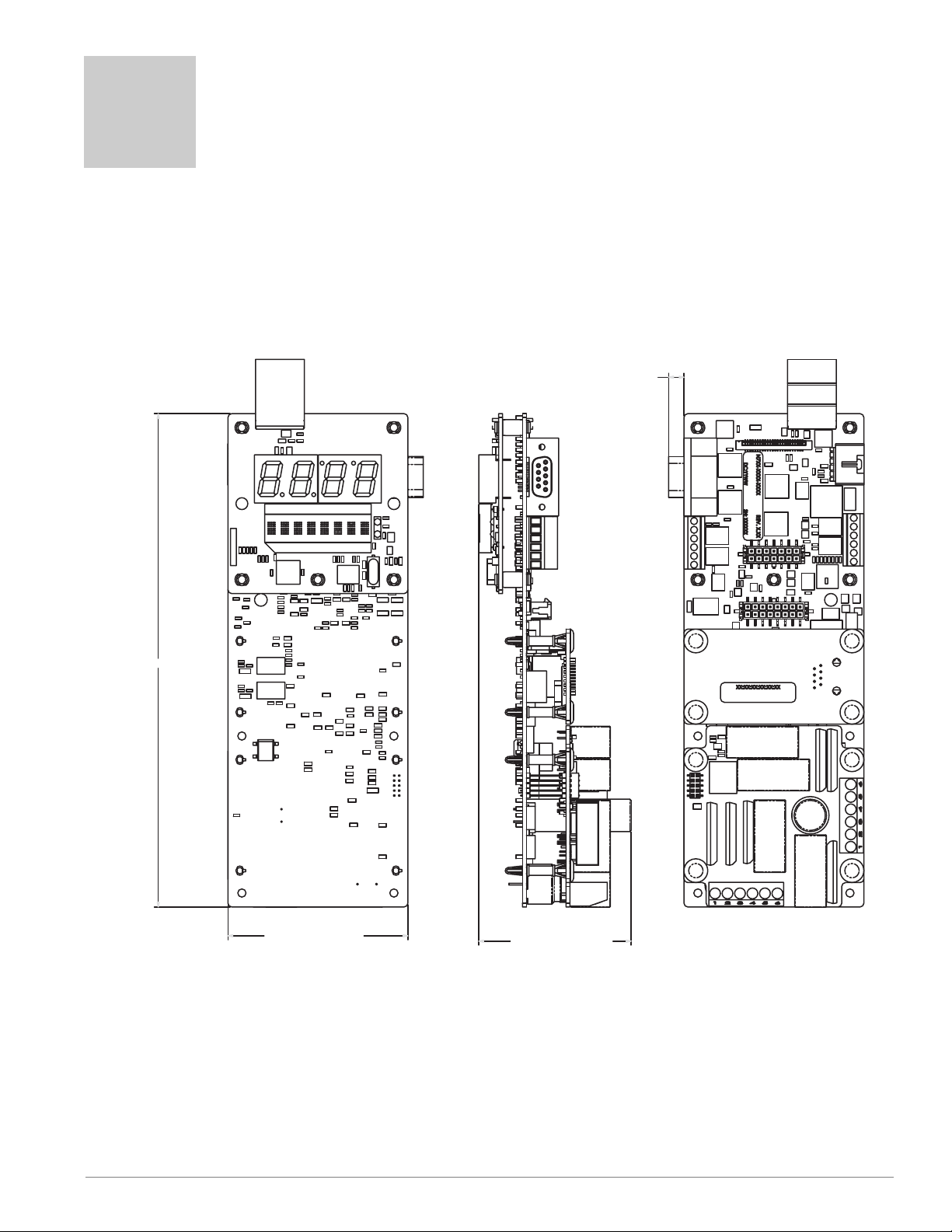
Series N7 Controller Dimensions
Vertical
Dimensions
with Add-on
Modules
6.15 mm
(0.24 in)
197.74 mm (7.79 in)
72.14 mm (2.84 in)
61.10 mm (2.41 in)
Page 6
Chapter 2: Install and Wire ■ 6 ■ Watlow Series N7
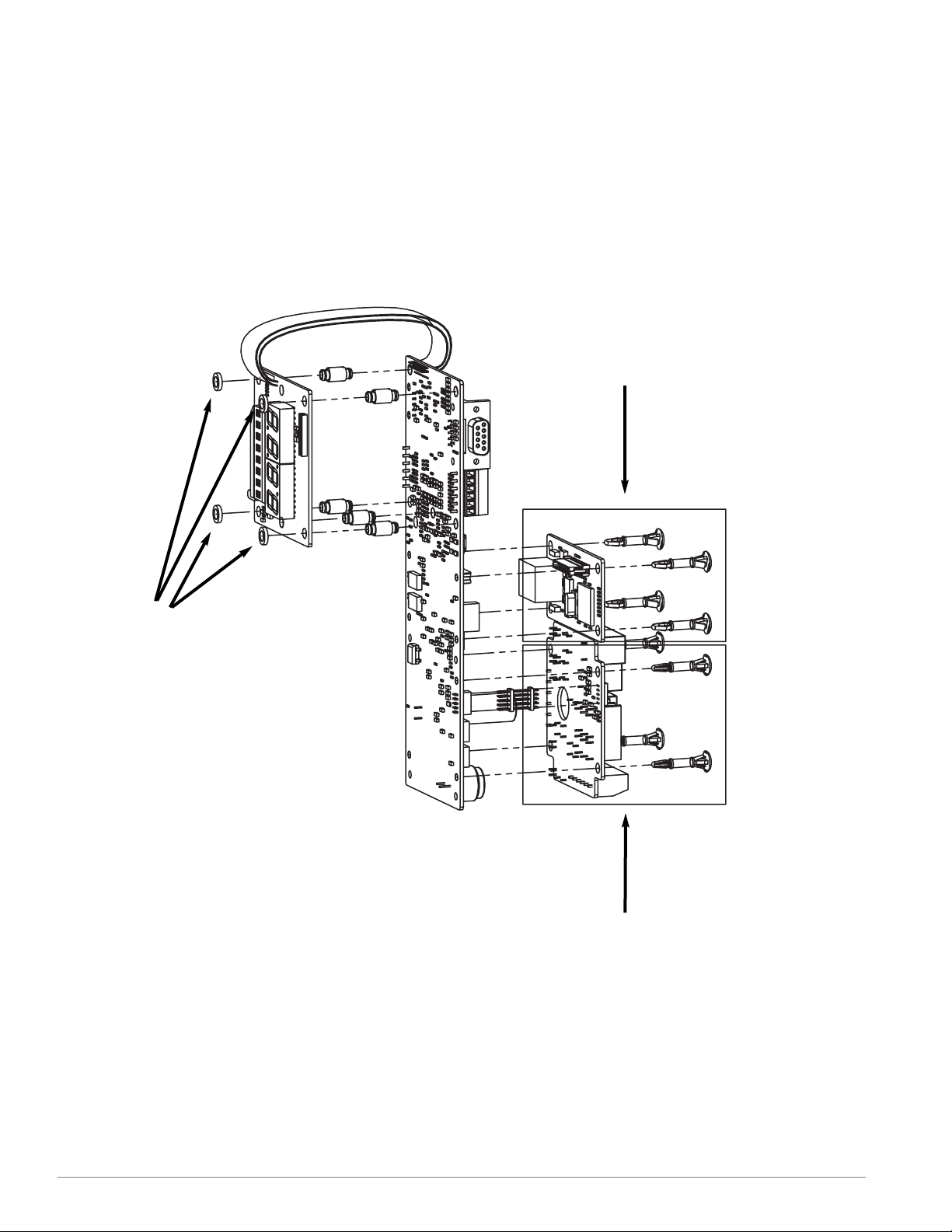
Vertical View with Add-on Modules
(exploded view)
(4) Nylon Spacers
(3/16 X 5/16 X 1/16)
Press spacer onto standoff
clips prior to mounting
Ethernet Add-on Module
(see Appendix for details)
Relay/High-Voltage Output Add-on
Module (see Appendix for details)
Page 7
Watlow Series N7 ■ 7 ■ Chapter 2: Install and Wire
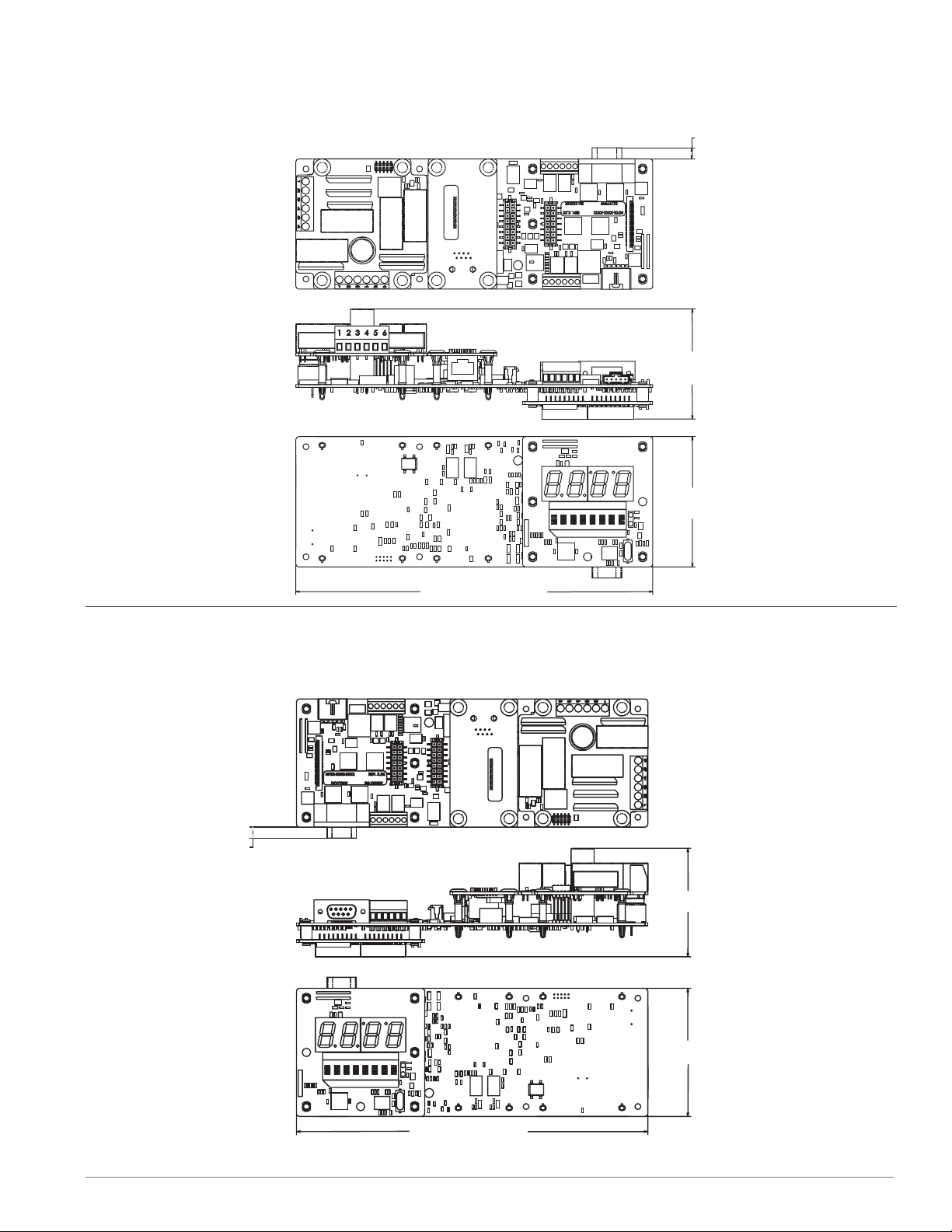
Horizontal Right
Horizontal Left
6.15 mm
(0.24 in)
61.10 mm (2.41 in)
72.14 mm (2.84 in)
6.15 mm
(0.24 in)
197.74 mm (7.79 in)
61.10 mm (2.41 in)
72.14 mm (2.84 in)
197.74 mm (7.79 in)
Page 8
Chapter 2: Install and Wire ■ 8 ■ Watlow Series N7
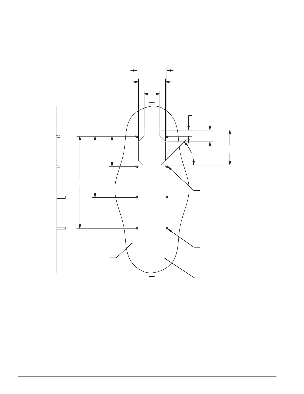
Cutout Standoff -Vertical
For Horizontal Left, rotate 90° counter-clockwise.
For Horizontal Right, rotate 90° clockwise.
4X 60.96 mm
(2.400 in
)
54.91 mm
(2.162 in
)
31.75 mm
(1.25 in
)
2X 60.96 mm
(2.400 in
)
2X 123.63 mm
(4.867 in
)
2X 186.57 mm
(7.345 in
)
2X 12.71 mm
(.500 in
)
2X 24.03 mm
(.946 in
)
71.12 mm
(2.800 in
)
4X 45
˚
Back side of pane
l
4X Blind #4-40 X .75 in
threaded standoff,
Pem BSOS-440-24
or equivalent.
(4X #4-40 X .25 in long
machine screw required
)
4X Blind #4-40 X .31 in
threaded standoff,
Pem BSOS-6440-10
or equivalent.
(4X #4-40 X .75 in long
machined screw required
)
C
L
C
L
Minimum panel thickness:
1.02 mm (0.040 in
)
Page 9
Watlow Series N7 ■ 9 ■ Chapter 2: Install and Wire
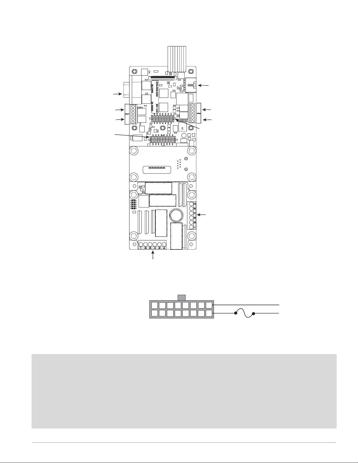
Location of Pins and Ports for Inputs and Outputs
Figure 9a — Power Wiring
• Nominal voltage: 24VÅ (ac)
• Class 2 power source required.
Ó
Warning: Use National Electric (NEC) or other country-specific standard wiring and safety practices when wiring and
connecting this controller to a power source and to electrical sensors or peripheral devices. Failure to do so may
result in damage to equipment and property, and/or injury
or loss of life.
Ó
Warning: If high voltage is applied to the 24VÅ (ac) input,
irreversible damage will occur.
Note:
To prevent ground loops, maintain isolation from input to
output when using switched dc or analog process outputs.
Use ungrounded thermocouples.
5-pin Master
9-pin Slave
Communications Port
Communications Port
Input 3
Input 4
16 pins
Power
Control Outputs 1 & 2
Event Inputs 1 to 4
Event Outputs 1 to 4
1
2
3
4
5
6
High Voltage Module
High-voltage Control Outputs 4
High-voltage Event Outputs 5 & 6
6
5
Input 2
4
3
2
Input 1
1
14 pins
Control Outputs 3 & 4
Process Outputs 1 & 2
Event Inputs 5 to 8
High Voltage Module
High-voltage
Control Outputs 1 to 3
16
14
15
13
12
345678
2
9
91011
1
1
L2
L1
Page 10

Ó
Warning: Use National Electric (NEC) or other country-specific standard wiring and safety practices when wiring and
connecting this controller to a power source and to electrical sensors or peripheral devices. Failure to do so may
result in damage to equipment and property, and/or injury
or loss of life.
Note:
To prevent ground loops, maintain isolation from input to
output when using switched dc or analog process outputs.
Use ungrounded thermocouples.
Chapter 2: Install and Wire ■ 10 ■ Watlow Series N7
Thermocouple
• J and K: –46 to 316°C (–50 to 600°F)
• Input impedance: >100 kΩ
Figure 10d — Input 4
Figure 10c — Input 3
Figure 10b — Input 2
Figure 10a — Input 1
3 456
2
1
3456
2
1
+
–
+
–
2
1
5
4
–
1
2
3
+
4
5
6
6
5
4
3
2
1
Input 2
Input 1
–
+
1
2
1
2
3456
1
Input 3
Input 4
1
2
3456
2
3
4
5
6
4
5
Page 11

Watlow Series N7 ■ 11 ■ Chapter 2: Install and Wire
Ó
Warning: Use National Electric (NEC) or other country-specific standard wiring and safety practices when wiring and
connecting this controller to a power source and to electrical sensors or peripheral devices. Failure to do so may
result in damage to equipment and property, and/or injury
or loss of life.
Note:
To prevent ground loops, maintain isolation from input to
output when using switched dc or analog process outputs.
Use ungrounded thermocouples.
2-wire or 3-wire RTD
• 100 Ω : –46 to 316°C (–50 to 600°F)
• DIN curve: 0.00385 ohms/ohms/°C
• <700 µA excitation
3-wire 2-wire
3-wire 2-wire
3-wire 2-wire
3-wire 2-wire
Figure 11d — Input 4
Figure 11c — Input 3
Figure 11b — Input 2
Figure 11a — Input 1
3 456
2
1
3 456
2
1
3
S1
S2
2
1
S3
6
S1
S2
5
S3
4
3 456
2
1
3 456
2
1
3
1
S2
2
1
6
S1
5
S2
2
3
4
5
6
6
5
4
3
2
1
Input 2
Input 1
4
S1
S3
S2
S1
1
2
3
1
2
3 456
S2
S1
1
2
3 456
4
S3
S2
S1
5
6
S2
S1
1
2
3
1
2
3 456
1
2
3 456
Input 3
Input 4
1
2
3
4
5
6
4
5
6
Page 12

Chapter 2: Install and Wire ■ 12 ■ Watlow Series N7
Ó
Warning: Use National Electric (NEC) or other country-specific standard wiring and safety practices when wiring and
connecting this controller to a power source and to electrical sensors or peripheral devices. Failure to do so may
result in damage to equipment and property, and/or injury
or loss of life.
Note:
To prevent ground loops, maintain isolation from input to
output when using switched dc or analog process outputs.
Use ungrounded thermocouples.
Process Inputs
• Voltage: 0 to 10VÎ (dc)
• Current: 0 to 20 mA
• Voltage input impedance: 50 kΩ
• Current input impedance: 100 Ω
–
Figure 12d — Input 4
–
Figure 12c — Input 3
Figure 12b — Input 2
–
Figure 12a — Input 1
3 456
2
1
3 456
2
1
3
Common
Current
2
1
Voltage
Common
6
Current
5
Voltage
4
1
2
+
+
3
4
5
6
6
5
4
3
2
1
Input 2
Input 1
–
+
+
Voltage
+
Current
+
Common
Voltage
+
Current
+
Common
1
2
3
4
5
6
1
2
3 456
1
2
3456
Input 3
Input 4
1
2
3
4
5
6
Page 13

Watlow Series N7 ■ 13 ■ Chapter 2: Install and Wire
Ó
Warning: Use National Electric (NEC) or other country-specific standard wiring and safety practices when wiring and
connecting this controller to a power source and to electrical sensors or peripheral devices. Failure to do so may
result in damage to equipment and property, and/or injury
or loss of life.
Note:
To prevent ground loops, maintain isolation from input to
output when using switched dc or analog process outputs.
Use ungrounded thermocouples.
–
Figure 13b — Process Output 2
–
Figure 13a — Process Output 1
Process Outputs
Current
• 0 to 20 mA at 20V maximum
• Load: 1 kΩ maximum
Volts
• 0 to 10VÎ (dc) at 20 mA maximum
• Load: 500Ω minimum
4
+
3
1
89101112
10
+
3 4567
2
1
3 4567
2
89101112
13
13
14
14
14 pins
Control Outputs 3 & 4
Process Outputs 1 & 2
Event Inputs 5 to 8
11
Page 14

Chapter 2: Install and Wire ■ 14 ■ Watlow Series N7
Ó
Warning: Use National Electric (NEC) or other country-specific standard wiring and safety practices when wiring and
connecting this controller to a power source and to electrical sensors or peripheral devices. Failure to do so may
result in damage to equipment and property, and/or injury
or loss of life.
Note:
To prevent ground loops, maintain isolation from input to
output when using switched dc or analog process outputs.
Use ungrounded thermocouples.
Figure 14b — Control Output 1
Figure 14c — Control Output 2
NOTE: Terminals 5, 6, 13 or 14 can be used for the common connection.
Figure 14d — Control Output 3
Figure 14e — Control Output 4
NOTE: Terminals 2, 5, 9 or 12 can be used for the common connection.
1
2
3 4567
891011 1 2
13
14
(common) 9
8
+
(common) 5
2
+
1
2
345678
91011
12
13
14
15
16
Control Outputs
If the high voltage output module is installed, the
state of each high-voltage control output mirrors the
state of the corresponding control output.
• Switched dc
• Current: 30 mA at 5VÎ (dc) nominal
Figure 14a — Switched DC
+
Load
5VÎ (dc) @ 30 mA (dc)
(common)
Internal Circuitry
16 pins
Outputs 1 & 2
Event Inputs 1 to 4
Event Outputs 1 to 4
Switched DC
+5VÎ (dc)
dc+
dc-
1
2
3
4
5
6
(common) 13
10
16
14
15
13
12
91011
1
345678
2
+
(common) 2
+
1
1
2
891011 1 2
3 4567
13
14
14 pins
Control Outputs 3 & 4
Process Outputs 1 & 2
Event Inputs 5 to 8
Page 15

Watlow Series N7 ■ 15 ■ Chapter 2: Install and Wire
Ó
Warning: Use National Electric (NEC) or other country-specific standard wiring and safety practices when wiring and
connecting this controller to a power source and to electrical sensors or peripheral devices. Failure to do so may
result in damage to equipment and property, and/or injury
or loss of life.
Ó
Warning: All high-voltage outputs must be powered by the
same source (phase), as shown in the example above.
Figure 15d — High-voltage Control Output 4
Figure 15c — High-voltage Control Output 3
Figure 15b — High-voltage Control Output 2
Figure 15a — High-voltage Control Output 1
HV Control Out 1 HV Control Out 2 HV Control Out 3 HV Control Out 4
N7_ _ - _ _ _ _ - 2 _ _ _ mechanical relay mechanical relay mechanical relay mechanical relay
N7_ _ - _ _ _ _ - 3 _ _ _ solid-state relay solid-state relay solid-state relay solid-state relay
N7_ _ - _ _ _ _ - 4 _ _ _ mechanical relay solid-state relay mechanical relay solid-state relay
N7_ _ - _ _ _ _ - 5 _ _ _ no-arc relay no-arc relay no-arc relay no-arc relay
• Operating temperature: 0 to
80° C
• Contact type: normally open
• Maximum current: 8 amps
• Maximum voltage: 250VÅ
(ac)
High-voltage Control Outputs
The state of each high-voltage control output mirrors the state of the corresponding control output.
6
45
3
2
1
6
45
3
2
1
6
45
3
2
1
Load
Load
Load
L2
L1
L2
L1
L2
L1
1
2
3
4
5
6
High Voltage Module
High-voltage
Control Outputs 1 to 3
1
2
3
4
5
6
1
2
3
45
6
Load
L1
L2
High Voltage Module
High-voltage Control Output 4
High-voltage Event Outputs 5 & 6
Page 16

Chapter 2: Install and Wire ■ 16 ■ Watlow Series N7
Ó
Warning: Use National Electric (NEC) or other country-specific standard wiring and safety practices when wiring and
connecting this controller to a power source and to electrical sensors or peripheral devices. Failure to do so may
result in damage to equipment and property, and/or injury
or loss of life.
Note:
To prevent ground loops, maintain isolation from input to
output when using switched dc or analog process outputs.
Use ungrounded thermocouples.
Event Inputs
• Voltage input
–0.5 to +0.5VÎ (dc), event input low (closed)
3 to 30VÎ (dc), event input high (open)
• Contact closure
less than 250 Ω, event input low (closed)
more than 10 kΩ, event input high (open)
Note: Terminals 5, 6, 13 or 14 can be used for the common connection.
Figure 16d — Event Input 4
Figure 16c — Event Input 3
Figure 16b — Event Input 2
Figure 16a — Event Input 1
16
15
14
13
12
(common) 6
91011
1
345678
2
–
Outputs 1 & 2
7
+
Event Inputs 1 to 4
Event Outputs 1 to 4
16 pins
1
2
3
4
5
6
15
(common) 14
16
14
15
13
12
91011
1
345678
2
16
14
15
13
12
16
14
15
13
12
91011
1
345678
2
(common) 6
16
(common) 14
91011
1
345678
2
8
+
–
–
+
+
–
Page 17

Ó
Warning: Use National Electric (NEC) or other country-specific standard wiring and safety practices when wiring and
connecting this controller to a power source and to electrical sensors or peripheral devices. Failure to do so may
result in damage to equipment and property, and/or injury
or loss of life.
Note:
To prevent ground loops, maintain isolation from input to
output when using switched dc or analog process outputs.
Use ungrounded thermocouples.
Watlow Series N7 ■ 17 ■ Chapter 2: Install & Wire
Note: Terminals 2, 5, 9 or 12 can be
used for the common connection.
Figure 17d — Event Input 8
Figure 17c — Event Input 7
Figure 17b — Event Input 6
Figure 17a — Event Input 5
+
–
(common) 5
1
891011 1 2
(common) 12
–
+
+
–
(common) 5
6
3 4567
2
13
1
3 4567
2
89101112
13
7
1
3 4567
2
89101112
14
13
14
13
14
14 pins
Control Outputs 3 & 4
Process Outputs 1 & 2
Event Inputs 5 to 8
1
2
89101112
(common) 12
–
+
14
3 4567
13
14
Page 18

Chapter 2: Install and Wire ■ 18 ■ Watlow Series N7
Ó
Warning: Use National Electric (NEC) or other country-specific standard wiring and safety practices when wiring and
connecting this controller to a power source and to electrical sensors or peripheral devices. Failure to do so may
result in damage to equipment and property, and/or injury
or loss of life.
Note:
To prevent ground loops, maintain isolation from input to
output when using switched dc or analog process outputs.
Use ungrounded thermocouples.
Event Outputs
• Switched dc
• 30 mA at 5VÎ (dc) nominal
Figure 18a — Switched DC
NOTE: Terminals 5, 6, 13 or 14 can be used for the common connection.
–
Figure 18e — Event Output 4
Figure 18d — Event Output 3
–
Figure 18c — Event Output 2
Figure 18b — Event Output 1
Load
Switched DC
5VÎ (dc) @ 30 mA (dc)
+5VÎ (dc)
(common)
dc+
dc-
Internal Circuitry
+
16
14
15
13
12
345678
13
12
13
12
(common) 13
16
14
15
16
14
15
16
14
15
13
12
91011
1
2
(common) 5
91011
1
345678
2
91011
1
345678
2
(common) 5
(common) 13
91011
1
345678
2
11
3
12
+
–
Outputs 1 & 2
Event Inputs 1 to 4
Event Outputs 1 to 4
16 pins
1
2
3
4
5
6
+
4
+
–
+
Page 19

Watlow Series N7 ■ 19 ■ Chapter 2: Install and Wire
Ó
Warning: Use National Electric (NEC) or other country-specific standard wiring and safety practices when wiring and
connecting this controller to a power source and to electrical sensors or peripheral devices. Failure to do so may
result in damage to equipment and property, and/or injury
or loss of life.
Ó
Warning: All high-voltage outputs must be powered by the
same source (phase), as shown in the example above.
Figure 19b — High-voltage Event Output 6
Figure 19a — High-voltage Event Output 5
High-voltage Event Outputs
• Solid-state relay
• Operating temperature: 0 to 80° C
• Contact type: normally open
• Maximum operating current: 0.4 amps
• Maximum operation voltage: 250VÅ (ac)
L1
1
L1
1
2
3
45
L2
2
3
45
Load
L2
Load
6
1
2
3
4
5
6
6
High Voltage Module
High-voltage Control Output 4
High-voltage Event Outputs 5 & 6
Page 20

Chapter 2: Install and Wire ■ 20 ■ Watlow Series N7
Ó
Warning: Use National Electric (NEC) or other country-specific standard wiring and safety practices when wiring and
connecting this controller to a power source and to electrical sensors or peripheral devices. Failure to do so may
result in damage to equipment and property, and/or injury
or loss of life.
Note:
To prevent ground loops, maintain isolation from input to
output when using switched dc or analog process outputs.
Use ungrounded thermocouples.
Communications using an EIA/TIA-232 to EIA/TIA-485 Converter
The circuit board illustration on page 9 shows the location of the master and slave ports.
Figure 20d — Slave, CMC Converter
• RS-232: 19,200 or 9,600 baud
• RS-485: 9,600 baud
• 0 to 16 nodes
Figure 20c — Master, CMC Converter
• 19,200 baud
• 0 to 16 nodes
• RS-485
Figure 20b — Slave, B&B Converter
• RS-232: 19,200 or 9,600 baud
• RS-485: 9,600 baud
• 0 to 16 nodes
Figure 20a — Master, B&B Converter
• 19,200 baud
• 0 to 16 nodes
• RS-485
Slave communications
The Series N7 can only respond to communications
on this port, as in the case of several N7s networked
to a Modbus master or a PC connected to this port to
monitor or adjust settings and process values. This is
how most Watlow controllers communicate.
Master communications
The Series N7 can initiate communications to controllers networked on this port. An implementation
might include a custom modbus I/O board and modbus motor control connected to the N7 master port
controlled by the N7's custom firmware.
120VÅ (ac)
120VÅ (ac)
TD (A)
GND
TD (B)
GND
485SD9TB
485SD9TB
Power
Supply
Power
Supply
12V Î (dc)
T+/R+
T–/R–
+
–
TD (A)
GND
TD (B)
GND
12V Î (dc)
+
–
T+/R+
T–/R–
5
1
6
6
4
2
345
789
2345
1
3
4
5
EIA-232
ADA485L
EIA-232
ADA485L
120VÅ (ac)
EIA-485
EIA-485
G
9VÎ
G
B
A
B
A
G
9VÎ
G
B
A
B
A
DI/ODI/O
DI/ODI/O
9VÎ (dc) (see note)
COM.
T–/R–
T+/R+
0219-0217-0000
7-ft. comms cable
120VÅ (ac)
9VÎ (dc) (see note)
COM.
T–/R–
T+/R+
0219-0217-0000
7-ft. comms cable
5
5
1
4
6
6
3
2
345
78
234
1
9
5
4
Page 21

Watlow Series N7 ■ 21 ■ Appendix
Appendix
A
Specifications
Controller
• Up to four sensor inputs, eight switched dc outputs, eight dc
inputs, two process outputs
• Battery backed, real-time clock
• One non-isolated slave communications channel
• One non-isolated master communications channel
• Optional ethernet communications module
• Optional high-voltage output module
Operator Interface
• Four-character, 0.56-inch, seven-segment display
• Eight-character, 0.2 inch, alphanumeric display
• Overlay interface supports up to 32 keys and LED indicator
lights
Overlay interface
• Switch closed input < 100 Ω
• Switch open input > 100 kΩ
• LED current limiting resistor: 200 Ω
• LED supply voltage: 5V
Operating Environment
•0 to 80°C (32 to 176°F) @ 0 to 90% RH, non-condensing
Standard Conditions For Specifications
• Ambient temperature 25°C (77°F) ±3°C, 24VÅ (ac), 50 to 60 Hz
Configured Sensor Inputs
• Update rate: 5Hz
Thermocouple
• Multiple channel applications require at least one ungrounded
thermocouple.
• Input current: 0.5 nA
• Maximum source resistance: 20 Ω
• Accuracy: ± 1.1°C (2°F)
• Drift: ± 0.10°C/°C (± 0.10°F/°F)
• Input ranges:
Type J: -46 to 316°C (-50 to 600°F)
Type K: -46 to 316°C (-50 to 600°F)
RTD
• 2- or 3-wire platinum
• DIN curve (.00385 curve)
• 700 µA maximum excitation current
• Accuracy: ± 1.1°C (2°F)
• Drift: ± 0.10°C/°C (± 0.10°F°/F)
• Range: -46 to 316°C (-50 to 600°F)
Voltage
• Input impedance 60 kΩ
• Input range: 0 to 12V
• Accuracy: ± 25 mV
• Drift: ± 5mV/F
Current
• Input impedance 100 Ω
• Input range: 0 to 22mA
• Accuracy: ± 40 µA
• Drift: ± 5 µA/F
Event Input
• Input high: 3 to 30V or >10 kΩ
• Input low: -0.5 to 0.5V or < 250 Ω
Outputs
Switched DC Outputs
• 5V at 30mA maximum
Voltage Output
• Range: 0 to 12V at 20 mA maximum
• Minimum: load impedance 500 Ω
• Accuracy: ± 100mV
• Drift: ± 2.1mV/F
Current Output
• Range 0 to 22mA at 20V maximum
• Maximum load impedance 1,000 Ω
• Accuracy: ± 100µA
• Drift: ± 4.3µA/F
Agency
•UL60730, c-UL File E43684
• EU LV Directive 72/23/EEC EN 60730
• EU EMC Directive 89/336/EEC
emissions
immunity
• NSF Option, File 49660-0003-000
• NAFEM Communications/Evaluate proper listing
• CSA standard E60730-2-9
Power/Line Voltage
• 24 VÅ (ac) power input (20.4 to 26.4Å (ac)), Class 2 power
source required
• 47 to 63 Hz
• 15VA maximum
• Program retention upon power failure via non-volatile memory
• Battery/real time clock option: six-year lithium battery, pro-
vides power upon backup power failure, operation resumption
after power recovery, ability to display time.
Audible Alarm
• Internal audible alarm, 85 dB @ 10cm @ 2 KHz. Output fre-
quencies supported: 250, 500, 1,000, 2,000, 4,000 Hz.
Storage Temperature
• -40 to 80°C (-40 to 176°F)
Optional High-Voltage Board
• Optional high-voltage board will have six outputs, either solid-
state relay, electromechanical relay or no-arc relay
Relay Specification:
Contact type: normally open
Maximum operating current: 8 A
Maximum operating voltage: 250VÅ (ac)
Pilot duty: 250 VA
Page 22

Appendix ■ 22 ■ Watlow Series N7
SSR Specification
Contact type: normally open
Maximum operating current: 0.4 A
Maximum operating voltage: 250VÅ (ac)
Pilot duty: 100 VA
No Arc Specification
Contact type: normally open
Maximum operating current: 8 A
Maximum operating voltage: 250VÅ (ac)
Note: These specifications are subject to change without
prior notice.
High-Voltage Modules Ordering Information
• A007-2660-0000 - 2 solid-state relays (0.4 A)
• A007-2660-0001 - 2 solid-state relays (0.4 A) and
4 mechanical relays (8 A)
• A007-2660-0002 - 6 solid-state relays (0.4 A)
• A007-2660-0003 - 4 solid-state relays (0.4 A) and
2 mechanical relays (8 A)
• A007-2660-0004 - 2 solid-state relays (0.4 A) and
4 no-arc relays*
Customer-Supplied Connectors
Standard I/O 16-pin connector housing - Molex part no.
43025-1600
Optional I/O 14-pin connector housing - Molex part no.
43025-1400
Pins - Molex part no. 43030-0007
*No-Arc Relay Definition:
A thyristor carries the load current for a brief period before the
relay contacts close. The voltage across the relay contacts prior
to closing is only a volt or two (the voltage drops across the
thyristor). When the relay contacts close, the load current flows
through the relay contacts, and the thyristor turns off. When
it’s time to turn the load off, the thyristor is gated ON just prior
to the relay contacts opening. As the relay contacts begin to
separate and the line voltage crosses zero, the thyristor again
goes into conduction and extinguishes the arcing between the
relay contacts. This great reduction in contact arcing (mainly
on relay opening) minimizes contact erosion and extends the
switch life of the relay.
Page 23

Watlow Series N7 ■ 23 ■ Appendix
Ordering Information and Model Numbers
Customer Name
Inputs 1 & 2
1 Input 1 & Input 2 thermocouple
2 Input 1 thermocouple, Input 2 process
3 Input 1 thermocouple, Input 2 RTD
4 Input 1 & Input 2 process
5 Input 1 RTD, Input 2 process
6 Input 1 & Input 2 RTD
Inputs 3 & 4
0 none
1 Input 3 & Input 4 thermocouple
2 Input 3 process, Input 4 thermocouple
3 Input 3 RTD, Input 4 thermocouple
4 Input 3 & Input 4 process
5 Input 3 RTD, Input 4 process
6 Input 3 & Input 4 RTD
Note: The thermocouple options for Inputs 3 and 4 need thermocouple population for Input 1.
Process Outputs 1 & 2, Event Inputs 5 to 8, Control Outputs 3 & 4
0 none
13 & 4 switched dc control outputs, event inputs
21 current output, 3 & 4 switched dc control outputs, event inputs
31 & 2 current outputs, 3 & 4 switched dc control outputs, event inputs
41 current output, 2 volts output, 3 & 4 switched dc control outputs, event inputs
51 volts output, 3 & 4 switched dc control outputs, event inputs
61 & 2 volts outputs, 3 & 4 switched dc control outputs, event inputs
71 volts output, 2 current output, event inputs
Ethernet Add-on Module
0 none
1 Ethernet
High-voltage Add-on Module
0 none
12 solid-state relays
24 mechanical relays and 2 solid-state relays
36 solid-state relays
42 mechanical relays; 4 solid-state relays
54 no-arc relays*; 2 solid-state relays
Horizontal or Vertical Display
1 vertical
2 horizontal left
3 horizontal right
Software and Customer Options
N 7
__ __ __ __ - __ __ __ __ - __ __ __ __
Page 24

Appendix ■ 24 ■ Watlow Series N7
Install or Replace the Relay/High Voltage Output Module (Z100-0817-000X)
1. Remove power from the controller.
2. Pre-assemble the circuit board spacers onto the
Relay/High Voltage Output circuit board.
• Insert the pointed end of a circuit board spacer
into one of the four mounting holes of the
Relay/High Voltage Output circuit board from
the side of the circuit board that has the output
terminal blocks.
• Using firm pressure, seat the circuit board spacer’s “head” onto the surface of the Relay/High
Voltage Output circuit board.
• Repeat with the remaining three circuit board
spacers.
3. Pre-assemble the board stacking header onto the
Relay/High Voltage Output circuit board.
• Align the pins of the board stacking header to
the socket on the Relay/High Voltage Output
circuit board. Make sure all pins are aligned
properly.
• Using firm pressure insert the board stacking
header into the socket.
• Make sure all pins of the board stacking header
are seated properly.
4. Install the Relay/High Voltage Output circuit board.
• Align the pins of the board stacking header to
the socket on the main circuit board. Make sure
all pins are aligned properly.
• Align the pointed end of the four circuit board
spacers with the four mounting holes on the
main circuit board.
• While maintaining alignment of the pins of the
board stacking header and the circuit board
spacers, firmly press the Relay/High Voltage
Output circuit board onto the main circuit
board.
•Verify that all pins of the board stacking header
and the circuit board spacers are seated properly.
5. Verify Output Wiring.
• Install wiring to the appropriate output terminals.
6. Test the Controller.
• Reapply power to the controller and test.
Figure 24 — Install the Relay/High Voltage Output Module.
Main Circuit Board
Relay/High Voltage
Output Circuit Board
Relay/High Voltage
Output Socket
Relay/High Voltage
Output Board
Sticking Header
Circuit Board Spacer
Relay/High Voltage
Output Socket
Pointed End
Head
Page 25

Watlow Series N7 ■ 25 ■ Appendix
Install or Replace the Ethernet Module (Z100-0816-0000)
1. Remove power from the controller.
2. Pre-assemble the circuit board spacers onto the
Ethernet circuit board.
• Insert the pointed end of a circuit board spacer
into one of the four mounting holes of the
Ethernet circuit board from the side of the circuit board that has the label on it.
• Using firm pressure seat the circuit board spacer until the head of the spacer is flush with the
surface of the Ethernet circuit board.
• Repeat with the remaining three circuit board
spacers.
3. Install the Ethernet circuit board.
• Align the Ethernet connector with the Ethernet
module connector.
• Align the pointed ends of the four circuit board
spacers with the four mounting holes on the
main circuit board.
• While maintaining alignment of the Ethernet
connectors and the circuit board spacers, firmly
press the Ethernet circuit board onto the main
circuit board.
•Verify that the Ethernet connector and the circuit board spacers are seated properly.
4. Verify Output Wiring.
• Install RJ-485 Ethernet connector.
5. Test the Controller.
• Reapply power to the controller and test.
Figure 25 — Install the Ethernet Module.
N7 Main Circuit Board
Ethernet Module Connector
Ethernet Module Circuit Board
RJ-485 Ethernet
Connector
Circuit Board Spacer
Page 26

Appendix ■ 26 ■ Watlow Series N7
Notes:
Page 27

Watlow Series N7 ■ 27 ■ Appendix
Declaration of Conformity
Series N7
Watlow Winona, Inc.
1241 Bundy Blvd.
Winona, MN 55987 USA
Declares that the following product:
Designation: Series N7
Model Numbers: N7 (any two letters or numbers) - (1 to 6) (0 to 6) (0 to 7) (0 or 1) - (0 to 5)
(1, 2 or 3) (any two letters or numbers)
Classification: Temperature control, Installation Category II, Pollution degree 2
Rated Voltage: 24 VÅ ac
Rated Frequency: 50 or 60 Hz
Rated Power Consumption: 15VA maximum
Meets the essential requirements of the following European Union Directives by using the relevant
standards shown below to indicate compliance.
89/336/EEC Electromagnetic Compatibility Directive
EN 60730-1:1995 with A1, 2, 3, Automatic electrical controls for household and similar
use - Part 1 General requirements. Clause H.26 EMC
requirements Immunity, Clause H.23 Class B* Emissions
EN 61000-4-2: 1996 With A1, 1998: Electrostatic Discharge Immunity
EN 61000-4-3: 1997: Radiated Field Immunity
EN 61000-4-4: 1995: Electrical Fast-Transient / Burst Immunity
EN 61000-4-5: 1995 With A1, 1996: Surge Immunity
EN 61000-4-6: 1996: Conducted Immunity
EN 61000-4-11: 1994: Voltage Dips, Short Interruptions and Voltage Variations
Immunity
EN 61000-3-2: ED.2. 2000: Harmonic Current Emissions
EN 61000-3-3: 1995 With A1:1998: Voltage Fluctuations and Flicker
*Class B emissions contingent upon use of a Steward Ferrite (28A2029-0A0) to Ethernet cable on main board.
73/23/EEC Low-Voltage Directive
EN 60730-1:1995 with A1, 2, 3, Automatic electrical controls for household and similar
use - Part 1 General requirements and Part 2-9:1995 -
Temperature sensing controls.
Raymond D. Feller, III Winona, Minnesota, USA
Name of Authorized Representative Place of Issue
General Manager February 2004
Title of Authorized Representative Date of Issue
Signature of Authorized Representative
4 and 5
4 and 5
Page 28

How to Reach Us
CUS
ER
TISF
CTI
Your Authorized Watlow Distributor:
Corporate Headquarters in the
U.S.:
Watlow Electric Manufacturing Co.
12001 Lackland Road
St. Louis, Missouri, USA 63146
Telephone: +1 (314) 878-4600
Fax: +1 (314) 878-6814
Europe:
Watlow GmbH
Industriegebiet Heidig
Lauchwasenstr. 1, Postfach 1165
Kronau 76709 Germany
Telephone: +49 (0) 7253-9400 0
Fax: +49 (0) 7253-9400-44
Watlow France S.A.R.L.
Immeuble Somag,16 Rue Ampère
Cergy Pontoise CEDEX 95307 France
Telephone: +33 (1) 3073-2425
Fax: +33 (1) 3073-2875
Watlow Italy S.R.L.
Via Meucci 14
20094 Corsico MI
Italy
Telephone: +39 (02) 4588841
Fax: +39 (02) 458-69954
Watlow Limited
Robey Close, Linby Industrial Estate
Linby Nottingham England, NG15 8AA
Telephone: +44 (0) 115 9640777
Fax: +44 (0) 115 9640071
Latin America:
Watlow de México
Av. Fundición #5
Col. Parques Industriales
Querétaro, Qro. México CP-76130
Telephone: +52 (442) 217-6235
Fax: +52 (442) 217-6403
Asia/Pacific:
Watlow Australia Pty., Ltd.
23 Gladstone Park Drive
Tullamarine, Victoria 3043 Australia
Telephone: +61 (39) 335-6449
Fax: +61 (39) 330-3566
Watlow China, Inc.
179 Zhong Shan Xi Road
Hong Qiao Cointek Bldg, Fl. 4, Unit P
Shanghai 200051 China
Telephone: +86 (21) 6229-8917
Fax: +86 (21) 6228-4654
Watlow Japan Ltd. K.K.
Azabu Embassy Heights 106
1-11-12 Akasaka
Minato-ku, Tokyo 107-0052 Japan
Telephone: +81 (03) 5403-4688
Fax: +81 (03) 5403-4646
Watlow Korea Co., Ltd.
3rd F. Taehong Bldg.
20-6, Seocho-gu, Yangjae-dong
Seoul, 137-130 Korea
Telephone: +82 (2) 575-9804
Fax: +82 (2) 575-9831
Watlow Malaysia Sdn Bhd
38B Jalan Tun Dr Awang
11900 Bayan Lepas
Penang Malaysia
Telephone: +60 (4) 641-5977
Fax: +60 (4) 641-5979
Watlow Singapore Pte. Ltd.
Ayer Rajah Crescent
#03-23, Ayer Rajah Industrial Estate
Singapore 139949
Telephone: +65 773 9488
Fax: +65 778 0323
Watlow Electric Taiwan
10F-1 No. 189
Chi-Shen 2nd Road
Kaohsiung, Taiwan
Telephone: +886 (7) 288-5168
Fax: +886 (7) 288-5568
TOTAL
CUS
TOMER
SATISF
ACTI
3 Year Warranty
ON
 Loading...