

Page 1
WATLOW SDAC User’s Guide 1
Introduction
The Serial Digital-to-Analog Converter (Serial DAC) is
an optional module for Watlow Anafaze Controllers. It
allows the controller to output precision analog voltages or currents. The Serial DAC is typically used for
precision open-loop control, motor or belt speed control, or phase-angle fired control.
This manual contains installation instructions, configuration information, and specifications.
Features
• Electrically isolated
• 0.003% resolution and linearity; factory calibrated
to 0.05% accuracy for voltage outputs and 0.5%
accuracy for current outputs. The Serial DAC can
also be recalibrated to 0.1% accuracy on current
output.
• User-selectable voltage or current output.
• Controller setup menus allow zero- and full-scale
value adjustments within the Serial DAC’s 0 to
10V
Î (dc) and 0 to 20 mAÎ (dc) output ranges.
Installing the Serial DAC
You will need the following tools:
• Power drill with 4-mm (0.15-in) bits
• Screwdriver
• Four screws up to size #6 (up to 3.8 mm). Choose
screws appropriate for your panel material.
• Wire strippers
ement
&
Contr
Watlow Controls
1241 Bundy Blvd., Winona, MN 55987
Customer Service
Phone: 1-800-414-4299
Fax: 1-800-445-8992
Technical Support
Phone: (507) 494-5656
Fax: (507) 452-4507
E-mail: wintechsupport@watlow.com
Part No. 0600-2185-2000 Rev. 4.0
December 2004
SDAC User’s Guide
To install the SDAC module:
1. Choose a wall or panel to install the Serial DAC.
For best results choose a location near the controller and in an area free from dust, excessive
heat and moisture and unauthorized personnel.
2. Drill four holes for screw mounting. See Figure 1
on page 2 for mounting hole dimensions and placement.
3. Place the Serial DAC in its mounting location so
that the screw holes in the Serial DAC line up
with the holes you have drilled. Insert the screws
in the holes and tighten.
4. Shut the system power off and wire the Serial
DAC to the controller and final control element.
Warranty
The Serial DAC is warranted to be free of defects in
material and workmanship for 36 months after delivery to the first purchaser for use, providing that the
units have not been misapplied. Since Watlow has no
control over their use, and sometimes misuse, we cannot guarantee against failure. Watlow’s obligations
hereunder, at Watlow’s option, are limited to replacement, repair, or refund of purchase price, and parts
which upon examination prove to be defective within
the warranty period specified. This warranty does not
apply to damage resulting from transportation, alteration, misuse, abuse, or improper fusing.
Measurement & Contr
SERIAL DAC
Power Input: 5Vdc, 300mA max.
Voltage Output: 10Vdc, 10mA max.
C
u
rre
U
S
n
E
t O
+5V IN
1
2
C
M
O
LK
C
3
4
C
IN
IN
DATA IN
FLASHING
=RUNNING
V
u
O
tp
P
u
P
t: 1
E
R
0
C
V
d
O
c, 2
N
O
D
U
0
U
C
TP
m
C
U
R
O
LT
A
G
A
T
U
m
O
T SE
REN
R
a
x.
S
O
T
LE
N
{
E
C
L
Y
T
{
+ OUT
5
OUT
-
6
P
IN
:
ol
Page 2
4 mm (0.2 in.)
ement
&
Contr
2 WATLOW SDAC User’s Guide
Wiring the Serial DAC
The Serial DAC provides a robust analog output signal. The module converts the proprietary Serial DAC
signal from the controller’s open collector output in
conjunction with the clock signal to an analog current
or voltage. See Figure 2 for wiring a Serial DAC. The
Serial DAC is user-configurable for voltage or current
output. Refer to Figure 3 for configuration information.
The Serial DAC optically isolates the controller’s control output from the load. One Serial DAC may be
powered by the 5VÎ (dc) supplied by a CLS200,
MLS300 or CPC400 controller at its output terminal
board. These controllers cannot provide sufficient current for more than one Serial DAC; use an external
power supply.
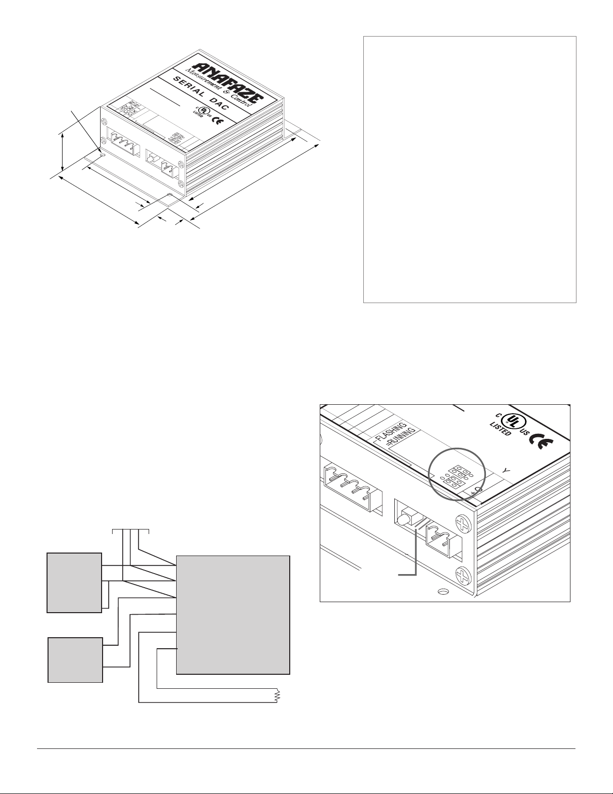
Figure 2. Single or Multiple Serial DACs with External
Power
Configuring Serial DAC Outputs
The Serial DAC’s voltage and current output is jumper
selectable. Refer to Figure 3. Configure the jumpers as
indicated on the Serial DAC label.
Figure 3. Voltage and Current Jumper Positions
Measurement
&
Control
DA
N
ut
O
t
O
E
Figure 1. Serial DAC Dimensions
WARNINGS
Ó
WARNING
The SDAC module is for indoor use only. To reduce
the risk of fire or electrical shock, install in a controlled environment relatively free of contaminants.
Ó
WARNING
Use a power supply with a Class 2 rating only.
NOTE
Tighten screw terminal connections to 0.5 to 0.6 Nm
(4.5 to 5.4 inch-pound).
NOTE
Use copper conductors only.
diameter
44 mm
(1.8 in.)
Measurement & Contr
SERIAL DAC
Power Input: 5Vdc, 300mA max.
Voltage Output: 10Vdc, 10mA max.
C
urrent O
U
S
E
:
+5V IN
1
COM IN
2
CLK IN
3
DATA IN
4
C
O
FLASHING
=RUNNING
V
O
utpu
P
P
t: 10V
E
R
C
d
O
c, 20
N
O
D
U
U
C
T
m
C
P
U
L
T
A
A
T
U
R
G
m
O
T
R
R
S
ax.
E
S
N
E
O
T
L
E
N
{
E
C
LY
T
{
+ OUT
5
OUT
-
6
P
IN
ol
119 mm (4.7 in.)
138 mm (5.5 in.)
91 mm
(3.6 in.)
76 mm
(3.0 in.)
8 mm
(0.3 in.)
10 mm
(0.4 in.)
Daisy chain up to
16 SDAC
IN
:
+5V I
1
COM IN
2
COPPER CONDUCTORS ONLY
CLK IN
3
DATA IN
4
FLASHING
CURRENT
=RUNNING
VOLTAGE
: 5Vdc, 300mA max.
utput: 10Vdc, 10mA max.
utput: 10Vdc, 20mA max.
OUTPUT SELECT
{
{
+ OUT
5
OUT
-
6
C
Power Supply
+V1 (5V)
0
+V2 (15V)
COM
Controller Output
SDAC Clock
Serial DAC
1 +5V In
2 COM In
3 CLK In
4 Data In
5 + Out
6
-
Out
Pins
Control Output
–
Load
+
Page 3

Setup and Operation
Using the Serial DAC with a Controller
Complete the following steps to set up your Serial
DAC:
1. Check the Output Select jumpers on the Serial
DAC. Make sure that both jumpers are set for
either voltage or current.
2. In the controller menus:
• Set the output type to SDAC (Serial DAC).
• Select the Serial DAC signal type: Voltage or
Current.
• Set the desired high and low output signal val-
ues.
The exact parameter names vary depending on the
controller. See your controller manual.
Testing the Serial DAC
1. In the controller, select the loop to be tested.
2. Set the control output to manual mode.
3. Set a percent output level.
4. Use a volt or current meter to verify the output
level of the Serial DAC.
Troubleshooting
The following section contains troubleshooting information for the Serial DAC.
Check the following first:
• Are the controller and Serial DAC wired and configured correctly?
• Are the inputs to the controller, such as thermocouples and RTDs, installed and working correctly?
Green Light on Serial DAC Does Not Light
Use a voltmeter to check:
• 5V power is present at the Serial DAC.
• Power is present at the controller.
Also, check data and clock line wiring, and make sure
that the controller’s output type is set to Serial DAC
for that loop.
Erratic and Incorrect Output Level
Check for reversed data and clock lines.
Output Level Incorrect, or No Output
• Check current and voltage jumper settings on the
Serial DAC.
• Check the controller’s voltage or current low and
high output level settings.
• Make sure the Serial DAC data input is wired to
the correct loop output.
Calibration Procedure
The standard Serial DAC is calibrated for precision
voltage output. To recalibrate your Serial DAC to output currents with 0.1% accuracy, follow these steps:
NOTE
This procedure should be performed only by a technician familiar with calibrating electronic equipment. The voltage or current meter used should have the appropriate precision and be
properly calibrated.
1. Remove the two plug-in terminals.
2. Unscrew either end panel.
3. Gently slide the card out.
4. Reinstall the plug-in terminals:
5. Recalibrate the circuit:
a. Connect the voltage or current meter to the out-
put.
b. Connect the Serial DAC to the controller.
c. Set the controller’s output to Manual Mode, 0%
Output.
d. Adjust the control labeled “zero” to get the
desired output — typically 4.000 mA for current
outputs.
e. Set the controller’s output to 100% output.
Adjust the control labeled “span” to get the
desired full scale output (typically 20.000 mA).
f. Repeat steps c through f until you have
achieved the desired accuracy.
6. Remove the plug-in terminal blocks from the
Serial DAC.
7. Gently slide the card back into the appropriate
casing slot.
8. Screw on the end panel.
9. Replace the plug-in terminal.
Specifications
Watlow Anafaze offers a Serial DAC for precision
open-loop control. The Serial DAC is jumper selectable
for a voltage or current output. Multiple Serial DAC
modules can be used with one controller.
The Serial DAC carries the CE mark.
Table 1. Serial DAC Environmental Specifications
Storage Temperature -20 to 60°C (-4 to 140°F)
Operating Temperature 0 to 50°C (32 to 122°F)
Humidity 10 to 95%, non-condensing
WATLOW SDAC User’s Guide 3
Page 4

4 WATLOW SDAC User’s Guide
Table 2. Physical Specifications
Table 3. Agency Approvals / Compliance
Inputs
The Serial DAC requires a proprietary serial data signal and the clock signal from the controller. The Serial
DAC also requires a 5VÎ (dc) power input.
Table 4. Screw Terminals
Table 5. Serial DAC Inputs
Table 6. Power Requirements
Analog Outputs
Table 7. Output Specifications
Parameter Description
Absolute Maximum
Common Mode
Voltage
Measured between output pins and controller common: 1,000V
Resolution 15 bits (plus polarity bit for voltage outputs)
(0.305 mV for 10V output range)
(0.00061 mA for 20 mA output range)
Accuracy (calibrated
for voltage output)
For voltage output: +/- 0.005V (0.05% at
full scale)
For current output: +/ 0.1 mA (0.5% at full
scale)
Temperature coefficient
440 ppm/°C typical
Isolation Breakdown
Voltage
1000V between input power and signals
Current 0 to 20 mA with 10V minimum compliance
(500 ohm load)
Voltage 0 to 10VÎ(dc) with 10 mA source
capability
Output Response
Time
1 ms typical
Update Rate Once per controller A/D cycle nominal.
Twice per second maximum for 60 Hz clock
rate.
Output changes are step changes due to
the fast time constant. All Serial DAC loop
outputs are updated at the same time.
Parameter Description
Voltage
4.75 to 5.25VÎ (dc) @ 300 mA maximum
Parameter Description
Data
4 mA maximum to DC COM
Open collector or HC CMOS logic levels
Clock
0.5 mA maximum to DC COM
Open collector or HC CMOS logic levels
Wire Gauge 24 to 12 AWG
Screw Terminal Torque
0.5 to 0.6 Nm (4.5 to 5.4
inch-pound)
CE Directive Electromagnetic Compatibility (EMC)
directive 89/336/EEC
UL® and C-UL® UL916, Standard for Energy
Management Equipment, File E177240
Weight 0.34 kg 0.76 lb
Length 138 mm 5.5 in
Width 91 mm 3.6 in
Height 44 mm 1.8 in
 Loading...