

Watlow SCR User Manual

Thermal Devices, Inc. Mount Airy, Maryland USA www.thermaldevices.com
y
QPAC
User’s Guide
0600-0027-0001 Rev D
Modular SCR
Power Control
150 to 1,000A
Made in the U.S.A.
August 2010
Thermal Devices, Inc. Mount Air
, Maryland USA www.thermaldevices.com

Thermal Devices, Inc. Mount Airy, Maryland USA www.thermaldevices.com
y
How to Use
this Manual
NOTE:
Details of a "Note" appear here, on the left
side of each page.
e
CAUTION:
Details of a "Caution"
appear here, on the left
side of each page.
WARNING:
Details of a "Warning"
appear here, on the left
side of each page.
Notes
A bold text "NOTE" marks a short message in the margin to alert you to an
important detail.
Safety Information
This user's guide also has boldface safety information notes to protect both
you and your equipment. Please be attentive to them.
The CAUTION symbol e (exclamation point) in the wide text column alerts
you to a "CAUTION," a safety or functional hazard which could affect your
equipment or its performance. A full explanation is in the narrow column on
the left side of the page.
The WARNING symbol
to a "WARNING," a safety hazard which could affect you and the equipment.
A full explanation is in the narrow column on the left side of the page.
(lightning bolt) in the wide text column alerts you
Your Feedback
We welcome comments or suggestions on this manual, please contact:
Technical Writer, Watlow Winona, 1241 Bundy Blvd, P.O. Box 5580, Winona,
MN 55987-5580. Phone: 507-454-5300; Fax: 507-452-4507. The QPAC User's
Guide is copyrighted by Watlow Winona, Inc. © August 2010 with all rights
reserved.
Technical Assistance
If you encounter a problem with your Watlow controller, review your conguration information to verify that your selections are consistent with your application: inputs, outputs, alarms, limits, etc. If the problem persists, you can get
technical assistance from your local Watlow representative (see back cover),
by e-mailing your questions to wintechsupport@watlow.com or by dialing +1
507-494-5656 between 7 a.m. and 5 p.m., Central Standard Time (CST). Ask
for for an Applications Engineer. Please have the following information available when calling:
• Complete model number • All conguration information
• User's Guide • Serial Number
The model, part number, and serial numbers can be found on the label on
the outside of the case.
How to Read the QPAC Model Number
The QPAC model number provides phase, supply voltage, amperage and control type
information, in that order. For example:
Fan Cooled 150Amp (150A @ 480V
480Vb (ac) Supply Burst Fired, Variable Time Base
3-Phase 2-Leg Open Heater, Shorted SCR Detector
b (ac), 3-phase)
Q32-481-150-BV2
Refer to the model number breakdown in the Model Number Information chart in the
Appendix for a complete listing.
2 QPAC User's Guide
Thermal Devices, Inc. Mount Air
How to Use this Guide
, Maryland USA www.thermaldevices.com

Thermal Devices, Inc. Mount Airy, Maryland USA www.thermaldevices.com
y
Contents
Table of Contents
Chapter 1
Starting Out With The QPAC Power Control 4
General Description 4
Steps To Put Your Power Control To Work 5
Chapter 2
How to Install and Wire the QPAC 6
System Planning 6
Mounting the QPAC 6
Input Signal Wiring 14
CA Control Card — AC Input Contactor 14
CD Control Card — DC Input Contactor 14
Process Input - AF, AL, BF and BV Control Cards 15
AF, AL, BF and BV Potentiometer Input 15
CD Control Card — Contact Closure Input Contactor 15
AF, AL, BF and BV DC Input Connections 16
AF, AL, BF and BV Auto/Manual Input 16
Interlock 16
Soft Start 17
AL Control Card Current Transformer Connections 17
Single- and Three-Phase Current Transformer Wiring 19
DH Card Operation — Heater Diagnostics 19
Setup Procedure 19
QPAC system Wiring Example 20
Chapter 3
How to Operate the QPAC 21
Setup Adjustments 21
Phase Rotation Adjustment for Q32 and Q33 21
Bias And Gain Adjustments for AF, AL, BF, BV 21
Current Limit Adjustments 23
Appendix
QPAC Troubleshooting 24
Specic to QPAC-33 Diagnostics 25
QPAC Specications 26
Model Number Information 28
Accessories 29
Warranty 31
Returns 31
QPAC User's Guide 3How to Use this Manual
Thermal Devices, Inc. Mount Air
, Maryland USA www.thermaldevices.com
Thermal Devices, Inc. Mount Airy, Maryland USA www.thermaldevices.com
y
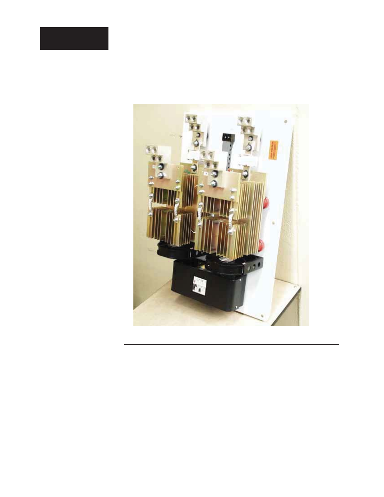
Starting Out
The Q32
SCR Power Control.
Chapter 1
Starting Out With The QPAC Power
Control
General Description
The QPAC Power Controls are a family of solid-state controls used for electric heating applications. A solid-state power control provides output power
that is proportional to the input command signal from a temperature control.
This proportional output power helps to produce a closely controlled heater
temperature, which saves energy and prolongs heater life by holding heater
elements at a nearly constant temperature.
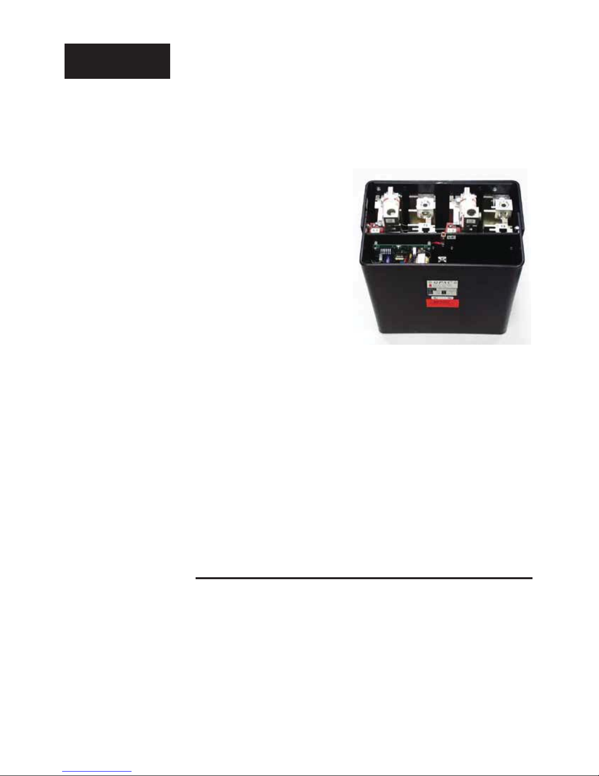
The three modules of the QPAC are the Power Base, Transformer and
Control Card. See the QPAC Modularity Overview below. Power Bases are
available in 150 to 1,000A ratings with UL508 listed and cULus in singlephase, three-phase two-leg and three-phase three-leg congurations. A
Transformer plugged into the Power Base allows the QPAC to operate
4 QPAC User's Guide Chapter 1: Starting Out
Thermal Devices, Inc. Mount Air
The QPAC has a modular construction with plug-in features for exibility.
, Maryland USA www.thermaldevices.com
Thermal Devices, Inc. Mount Airy, Maryland USA www.thermaldevices.com
y
Control Cards
Starting Out
Plug-in transformers (50/60 Hz.)
• Solid-state contactor, ac input, CA
• Solid-state contactor, dc input, CD
• Burst ring (zero cross) xed time base, BF
• Burst ring (zero cross) variable time base, BV
• Phase angle control, AF *
• Phase angle control with current limiting, AL *
* Note: For 1Ø and 3Ø, 3-leg controls only; not for
3Ø, 3-leg controls.
QPAC Modularity
Overview.
• 120Vb (ac)
• 208/240Vb (ac)
• 380Vb (ac)
• 415Vb (ac)
• 480Vb (ac)
• 575Vb (ac)
Power Bases With Motherboards
• QPAC-01: 1Ø, 150 to 1,000A
• QPAC-32: 3Ø, 2-leg, 150 to 1,000A
• QPAC-33: 3Ø, 3-leg, 150 to 1,000A
on any voltage from 120 to 575Vb (ac). The plug-in Control Card sets the
QPAC’s ring mode. Control Cards are available in solid-state contactor, burst
ring (zero cross) or phase angle ring with a wide variety of options. This
modular approach, using a standard Power Base with plug-in transformers
and Control Cards, allows power control users, distributors and OEMs to
maintain minimum inventories while still providing rapid service.
The different QPACs provide the types of power control needed for different power sources and loads. The QPAC-01 is designed for all single-phase
power sources and loads. The QPAC-32 is for three-phase zero cross applications such as resistance heating elements, balanced or unbalanced. The
QPAC-33 is best suited for balanced three-phase, phase angle applications
requiring soft start or current limiting, or with inductive loads.
Steps To Put Your Power Control To Work
To put your QPAC to work, we suggest the following steps:
QPAC User's Guide 5Chapter 1: Starting Out
Thermal Devices, Inc. Mount Air
• Read the User's Guide.
• Plan your installation and wiring.
• Mount the QPAC.
• Wire your QPAC to the system.
• Start the system and, if applicable, adjust the bias and gain on the QPAC.
• That's all there is to it!
, Maryland USA www.thermaldevices.com

Thermal Devices, Inc. Mount Airy, Maryland USA www.thermaldevices.com
y
Mounting
WARNING:
To avoid potential
electric shock and other
hazards, all mounting
and wiring for the QPAC
must conform to the
National Electric Code
(NEC) and other locally
applicable codes.
Chapter 2
How to Install and Wire the QPAC
System Planning
This chapter tells you how to install the QPAC. All mounting and wiring
information is right here. Watlow power controls are thoroughly tested before
leaving the factory, so the QPAC is ready to install when you receive it.
This chapter is divided into three sections that describe the three steps to
installing the QPAC: mounting, power wiring and control card wiring. The rst
section lists the mounting information for each of the three types of QPACs,
which, depending on amperage, use one of two case styles. The second
section describes the power and load wiring of the QPACs and semiconductor fuses, if required. The last section describes the input signal wiring to the
QPAC Control Card.
Before you begin working, read through this chapter to gain an under-
standing of the entire installation. Consider the installation carefully. Plan the
power, load and input signal wiring before mounting the QPAC. Also refer
to any noise guidelines in the temperature control documentation before
proceeding.
Mounting the QPAC
The physical size and mounting dimensions of the QPACs are different for
different current ratings. Find the "Case Style" photo on the next pages that
match your QPAC. The table and gure accompanying each case style will
give you corresponding physical dimensions and mounting footprint. The
table also indicates if the units are equipped with fans and externally-mounted fuses. All QPACs must be mounted vertically, power connections on top,
for proper cooling. Use the wiring data table below for wire sizes and bending
radii.
6 QPAC User's Guide Chapter 2: Install & Wire
Thermal Devices, Inc. Mount Air
, Maryland USA www.thermaldevices.com

Thermal Devices, Inc. Mount Airy, Maryland USA www.thermaldevices.com
y
Mounting
Template for Fuse Holders
with QPAC 150A, 575V.
(0.225 in)
7.9mm
(5/16 in - 18)
3.8mm
(0.15 in)
88.9mm (3.50 in) minimum
106.4mm (4.19 in) maximum
19.1mm
(0.75 in)
5.7mm
Top View
31.8mm
(1.25 in)
40.4mm
(1.59 in)
25.4mm
(1.00 in)
Ensure nut and washer
are used below and above fuse
Right Side View
21.1mm
(0.83 in)
13.5mm
(0.53 in)
9.7mm
(0.38 in)
Template for Fuse Holders
with QPAC 200 and 300A,
575V.
152.0mm
(6.00 in)
103.17mm
(4.062 in)
Top View
9.7mm
(0.38 in) Typical
24.6mm
(0.97 in)
9.5mm
(0.375 in - 16)
50.8mm
(2.00 in)
Right Side View
12.7mm
(0.50 in)
12.7mm
(0.50 in)
7.1mm
(0.281 in)
QPAC User's Guide 7Chapter 2: Install & Wire
Thermal Devices, Inc. Mount Air
Ensure nut and washer
50.8mm
(2.00 in)
are used below and above fuse
25.4mm
(1.00 in)
, Maryland USA www.thermaldevices.com

Thermal Devices, Inc. Mount Airy, Maryland USA www.thermaldevices.com
y
Case Style C
Mounting
QPAC Case Style C.
QPAC Case Style C
Overall Dimensions.
e
CAUTION:
Mount the QPAC vertically
(height dimension vertical)
for proper cooling. Failure
to do so could result in
power control malfunction.
Model Amps Height Width Depth Fans Fuses
QPAC-01
QPAC-01
QPAC-01
QPAC-32
QPAC-32
QPAC-32
QPAC-33
QPAC-33
QPAC-33
Note: On 575 V~(ac) applications, the fuses are mounted external to the QPAC.
150
330mm (13 in)
200
330mm (13 in)
300
330mm (13 in)
150
330mm (13 in)
200
330mm (13 in)
300
330mm (13 in)
150
330mm (13 in)
200
330mm (13 in)
300
330mm (13 in)
175mm (6.9 in)
175mm (6.9 in)
175mm (6.9 in)
348mm (14.0 in)
348mm (14.0 in)
348mm (14.0 in)
533mm (21.0 in)
533mm (21.0 in)
533mm (21.0 in)
260mm (10.25 in)
260mm (10.25 in)
260mm (10.25 in)
260mm (10.25 in)
260mm (10.25 in)
260mm (10.25 in)
260mm (10.25 in)
260mm (10.25 in)
260mm (10.25 in)
1
on heat sink
1
on heat sink
1
on heat sink
2
on heat sink
2
on heat sink
2
on heat sink
3
on heat sink
3
on heat sink
3
on heat sink
WARNING: Shock Hazard
Heatsinks are electrically
Live.
QPAC Case Style C,
QPAC-01, 150, 200, 300A
Single-Phase Mounting
Footprint.
178mm
(7.00 in)
MOUNT
U
P
FAN
89mm
(3.50 in)
10mm (0.38 in)
2 PL
92mm
(3.63 in)
330mm
(13.00 in)
299mm
(11.75 in)
e
8 QPAC User's Guide Chapter 2: Install & Wire
Thermal Devices, Inc. Mount Air
, Maryland USA www.thermaldevices.com

Thermal Devices, Inc. Mount Airy, Maryland USA www.thermaldevices.com
y
Case Style C
Mounting
QPAC Case
Style C, Q32,
150, 200, 300A,
3-Phase, 2-Leg
Mounting Footprint.
e
CAUTION:
Mount the QPAC vertically (height dimension
vertical) for proper
cooling. Failure to do
so could result in power
control malfunction.
FAN
178mm
(7.00 in)
356mm
(14.00 in)
U
P
MOUNT
FAN
89mm
(3.50 in)
10mm (0.375 in)
4 PL
16mm
(0.63 in)
298mm
(11.75 in)
33mm
(13.00 in)
e
WARNING: Shock Hazard
Heatsinks are electrically
Live.
QPAC Case Style C,
Q33, 150, 200, 300A,
3-Phase, 3-Leg Mounting
Footprint.
FAN
178mm
(7.00 in)
U
P
FAN
MOUNT
178mm
(7.00 in)
533mm
(21.00 in)
FAN
92mm
(3.63 in)
10mm (0.375 in)
4 PL
e
16mm
(0.63 in)
298mm
(11.75 in)
33mm
(13.00 in)
QPAC User's Guide 9Chapter 2: Install & Wire
Thermal Devices, Inc. Mount Air
, Maryland USA www.thermaldevices.com

Thermal Devices, Inc. Mount Airy, Maryland USA www.thermaldevices.com
y
Case Style E
Mounting
QPAC Case Style E.
QPAC Case Style E
Overall Dimensions.
Model Amps Height Width Depth Fans Fuses
QPAC-01
QPAC-01
QPAC-32
QPAC-32
QPAC-33
QPAC-33
400 to 600
800 to 1,000
400 to 600
800 to 1,000
400 to 600
800 to 1,000
685mm (27 in)
685mm (27 in)
685mm (27 in)
840mm (33 in)
840mm (33 in)
840mm (33 in)
430mm (17 in)
430mm (17 in)
535mm (21 in)
535mm (21 in)
685mm (27 in)
685mm (27 in)
300mm (11.7 in)
340mm (13.3 in)
300mm (11.7 in)
340mm (13.3 in)
300mm (11.7 in)
340mm (13.3 in)
111 on-board
1 on-board
222 on-board
2 on-board
333 on-board
3 on-board
e
CAUTION:
Mount the QPAC vertically (height dimension
vertical) for proper
cooling. Failure to do
so could result in power
control malfunction.
WARNING:Shock Hazard
Heatsinks are electrically
Live.
QPAC Case Style E
Mounting Footprint.
22mm
(0.88 in)
Width
L1 L2 L3
U
P
MOUNT
T1 T3
FAN
ELECTRONICS
PACKAGE
(Signal Connects Inside)
FAN
Height
GROUND
10 QPAC User's Guide Chapter 2: Install & Wire
Thermal Devices, Inc. Mount Air
22mm
(0.88 in)
Fan Voltage Input
12.7mm (0.5 in)
, Maryland USA www.thermaldevices.com

Thermal Devices, Inc. Mount Airy, Maryland USA www.thermaldevices.com
y
Wiring
QPAC Wiring Data.
Load
Current
(amps)
Semiconductor Fuse Rat-
ing (amps.)
150 200 3/0 102mm (4 in) 4 to 3/0 *onboard 240 in/lb 3/16 in
200 250 250 MCM 114 mm (4.5 in) 6 to 350 MCM *onboard 375 in/lb 3/8 in
300 400 500 MCM 203 mm (8 in) 4 to 500 MCM *onboard 375 in/lb 3/8 in
400 500 Dual 350 MCM 380mm (15 in) 2 to 600 MCM onboard 500 in/lb 1/2 in
500 600 Dual 350 MCM 380mm (15 in) 2 to 600 MCM onboard 500 in/lb 1/2 in
600 800 Dual 500 MCM 380mm (15 in) 2 to 600 MCM onboard 500 in/lb 1/2 in
800 1,000 Quad 250 MCM 380mm (15 in) 2 to 600 MCM onboard 375 in/lb 3/8 in
1,000 1,250 Quad 350 MCM 380mm (15 in) 2 to 600 MCM onboard 375 in/lb 3/8 in
Minimum
Recommended
Wire Size
Bending Radius Wire Sized that
Lugs Accept
Fuse
Mounting
Lug
Torque
*The fuses are external in Style C power controls over 575Vb (ac).
Internal
Allen
Wrench
QPAC User's Guide 11Chapter 2: Install & Wire
Thermal Devices, Inc. Mount Air
, Maryland USA www.thermaldevices.com
 Loading...