

Page 1
RMA PLUS
User Guide
1241 Bundy Boulevard, Winona, Minnesota USA 55987
Phone: 1-507-454-5300 | Fax: 1-507-452-4507
http://www.watlow.com
Document #: 10-32813 Rev A; June 07, 2019
Page 2

Table of Contents
Technical Support 5
Contacting Technical Support 5
3-Year Product Warranty 5
Returning a Product 5
Chapter 1 | About the RMA PLUS 6
Conceptual Overview 6
Specifications 6
RMA PLUS Safety Compliance 7
Ordering Part Numbers 8
Chapter 2 | Mounting and Wiring 9
Mounting (DIN Rail or Chassis) 9
Rail Mount 9
Chassis Mount 10
Wiring Power and Communications 10
Slot C Power and Communications 10
Low Power Input Requirements (same for all RM models) 10
Power and Communication Slots 11
Earth Ground for USBH and USBD Connectors 11
RMAPLUS Communications Options 12
RMAP-AAXX-XXXX: Standard Options Model 12
RMA PLUS with Communication Options RS-232/RS-485 13
System Wiring 14
Split Rail Power Needs 14
Chapter 3 | Getting Started 15
About the USB Drives 15
Installing Device Drivers 15
Accessing and Working with Files on the USBDrives 19
Chapter 4 | Configuration 22
Overview 22
Configuration File Formats 22
Configure Ethernet with Dashboard 23
Configuring RMA PLUS with CSV Creator 26
Overview 26
Initial Setup 26
General Usage of CSVCreator 27
Device Tree 27
Location Dropdown 27
File Type Dropdown 27
Drive Status Buttons 27
Saving Configuration Files 28
Configuring Modbus® Registers 28
Document #10-32813 Rev A; June 07, 2019
Page 2 of 69
Page 3

Selecting Parameters for Modbus® and Data Logging 28
Modbus® Default Register Addressing 29
Legacy Modbus® Register Addressing 30
System Configuration Settings 31
Data Log Configuration 31
HTTPs Web Server Configuration 32
Applying Configuration Changes to the RMA PLUS 32
Data Types for Configuration Files 32
Busses 33
Bus 0: Nothing 33
Bus 1: Inter-Module Bus 33
Bus 2: Standard Bus 33
Bus 4, 5: Modbus® RTU Master 33
Producer / Consumer Data 33
Chapter 5 | Features 36
USB Composite Device 36
Mini-B USBConnection for Fast Communication to RM Devices 36
Three Drives in Mass Storage Class 37
Data Logging 37
Ethernet 39
3-Port 10/100 Managed Ethernet Switch 39
Broadcast Storm Protection 39
Multicast Storm Protection 40
Port Mirroring 40
MAC Filter 40
Addressing 40
NetBIOS Name Service 40
Intermodule Bus Over Ethernet 40
Modbus® TCP Server 41
HTTP Server 42
Configuring Read Only Diagnostic Web Page 42
Token Format 45
TFTP Server 46
Notes 47
SNTP Client 47
Wireshark 47
Ethernet Members in RMAPLUS 47
Modbus® RTU 49
Testing Modbus® RTU Communications 50
Non-Volatile Memory 51
Standard Bus and Intermodule Bus Addressing 51
Address Segmentation 51
Document #10-32813 Rev A; June 07, 2019
Page 3 of 69
Page 4

Intermodule Bus 52
System Configuration File 53
Chapter 6 | Standard Objects Reference 55
Alarm 2 55
Calibration 56
Consumer Data 56
Device 58
LED 58
Real-Time Clock 61
Standard Bus and Intermodule Bus 62
Volume 62
Appendix 1 RMA PLUS Setup Keys Reference 64
Appendix 2 Declaration of Conformity 67
Appendix 3 List of RMA PLUS Figures 69
Document #10-32813 Rev A; June 07, 2019
Page 4 of 69
Page 5

Technical Support
Contacting Technical Support
If you encounter a problem with your Watlow controller, review the configuration of inputs, outputs, alarms, limits, etc. to
verify that the selections are consistent with your application. Often that’s all that is needed to resolve an issue.
If the problem persists, e-mail wintechsupport@watlow.com or call +1 (507) 494-5656 from 7am - 5pm Central Time and
ask for an Application Engineer. Please have the following information available:
l Complete model number
l All configurations
l User’s Guide
l Factory Page
3-Year Product Warranty
The RMA PLUS is warranted by Watlow for a period of 36 months in accordance with the terms and conditions set forth
on Watlow’s website, which may be accessed at www.watlow.com/terms.
Returning a Product
1. Obtain a Return Material Authorization (RMA) Number.
This RMA number is REQUIRED to return a product for any reason.
l If you do not know why the product failed, call +1 (507) 494-5656 to speak to an Application Engineer.
l After discerning the reason for the return, call Watlow Customer Service at +1 (507) 454-5300 for the RMA number.
l When you call, you must provide:
l Your P.O. number
l Ship-to address
l Bill-to address
l Detailed description of the problem
l Any special instructions
l Name and phone number of person returning the product
l Method of return shipment
2. Ship the Return
l Clearly indicate the RMA number on the outside of the carton and on all paperwork returned.
l Ship on a Freight Prepaid basis.
3. We will examine the returned product and RMA number to verify the reason for return.
l In cases of manufacturing defect, we will enter a repair order, replacement order or issue credit for material returned.
In cases of customer misuse, we will provide repair costs and request a purchase order to proceed with the repair
work.
l To return products that are not defective, goods must be in new condition, in the original boxes and they must be
returned within 120 days of receipt. A 20 percent restocking charge is applied for all returned stock controls and
accessories.
l If the unit cannot be repaired, you will receive a letter of explanation. and be given the option to have the unit returned
to you at your expense or to have us scrap the unit.
l Watlow reserves the right to charge for no trouble found (NTF) returns.
Document #10-32813 Rev A; June 07, 2019
Page 5 of 69
Page 6

Chapter 1 | About the RMA PLUS
The RMA PLUS is a remote access, high-speed communication gateway that provides access to all Watlow RM control modules in a system, using up to four busses via Ethernet, USB or serial.
RMA PLUS routes standard bus transactions over Ethernet and USB to all devices connected to the intermodule bus
network to allow for easy system configuration and monitoring. All units come standard with a built-in managed Ethernet
switch and two Ethernet jacks. RMA PLUS also connects to third-party and legacy devices, acting as a gateway
between Modbus® TCP and Modbus® RTU. Up to three Modbus® TCP sessions, three standard bus over Ethernet
sessions and one standard bus over USB session are available.
l Built-in Ethernet switch offers port mirroring for troubleshooting
l Built-in Ethernet switch protects from broadcast and multicast storms
l Integrated USB provides real-time communication to PC
l Modbus® TCP and Modbus® RTU allow you to build tables based on your unique needs and manage custom data sets
asynchronously to fieldbus activity
l Modbus® TCP and Modbus® RTU connect to third-party and legacy devices
Conceptual Overview
l On initialization, the RMA PLUS reads the file “nor:\Setup.csv” (from the included USBdrive) for feature configuration
and file paths.
l Gateway busses and enabled features (i.e. Modbus® TCP, Data Logging, etc) are instantiated.
l Delivery and transfer speeds for discovery are mere seconds.
l Gateway busses interact with target devices to read/write data points. RMA PLUS logs any data point in the system,
available as .csv files for easy access.Standard units are equipped to handle 16GB of data.
l Fieldbusses interact with gateway bus data sets, not directly with the target device.
Specifications
Feature Specification
EZ-ZONE Product Compatibility
Supply Voltage
Power
Ethernet Communication
Standard Communication
Additional Communication Options
USB
Real Time Clock with Battery
Backup
l Any Watlow product with high-speed or low-speed bus capabilities, i.e.:
l EZ-ZONE RM (C, E, H, L, S) version 9.0+ intermodule bus
l EZ-ZONE PM, RUI, ST standard bus
l EZ-ZONE RM (F, G, UH, Z) intermodule bus
l POWERGLIDE intermodule bus
l 24V
l 4W, 9VA
l 10/100 Ethernet with managed switch
l Ethernet
l USB
l Serial (‘C’ connector)
l Modbus® TCP over Ethernet
l Isolated EIA 232/485, Modbus® RTU
l USB 2.0 device
l Mini USB connector
l Composite device: vendor specific and mass storage classes
l Battery typical lifetime rating of 10 years
Document #10-32813 Rev A; June 07, 2019
Page 6 of 69
Page 7
Feature Specification
l Lithium battery
Data Logging
Memory Card
Gateway
Software Compatibility
l Maximum of 2000 data points
l Maximum of 500 unique data points per bus and zone
l File storage on embedded micro SD memory
l .CSV log files accessed via USB device port
l Micro SDHC (4-32GB)
l 4GB class 4 SDHC on standard models (operating temperature: -25 to 85C)
l 16GB class 10 SDHC on data log models (operating temperature: -40 to 85C)
l -4 to 185F (-20-85C) ambient rating, non-volatile memory
l All module parameters are backed up in memory
l Modbus® TCP to standard bus or intermodule bus
l Modbus® TCP to Modbus® RTU
l Modbus® RTU to standard bus or intermodule bus
l Modbus® RTU to Modbus® RTU
Via USB, Serial, or Ethernet
l Watlow Dashboard
l Watlow EZ-ZONE COMPOSER
l LabVIEW (by National Instruments)
Via Serial only
l Watlow EZ-ZONE Configurator
RMA PLUS Safety Compliance
Device has beenevaluatedto United States and Canadianrequirements for Process Control Equipment andlisted at Underwriters Laboratories® as
CCN: QUYX, QUYX7FileE185611to UL/EN 610101-1, CSA C22.2 #61010-1 andand recognized as CCN: QUYX2, QUYX8FileE185611UL/EN 61010-
1, CSA C22.2 #61010-1.
Device has beenevaluatedto United States and Canadianrequirements and listed at Underwriters Laboratories® as CCN: QUZW, QUZW7 File
E184390 to ANSI/ISA12.12.01, CSA C22.2 NO. 213-17 Class I, Division 2, Groups A, B, C, and D for Hazardous Locations. See:www.ul.com
Document #10-32813 Rev A; June 07, 2019
Page 7 of 69
Page 8
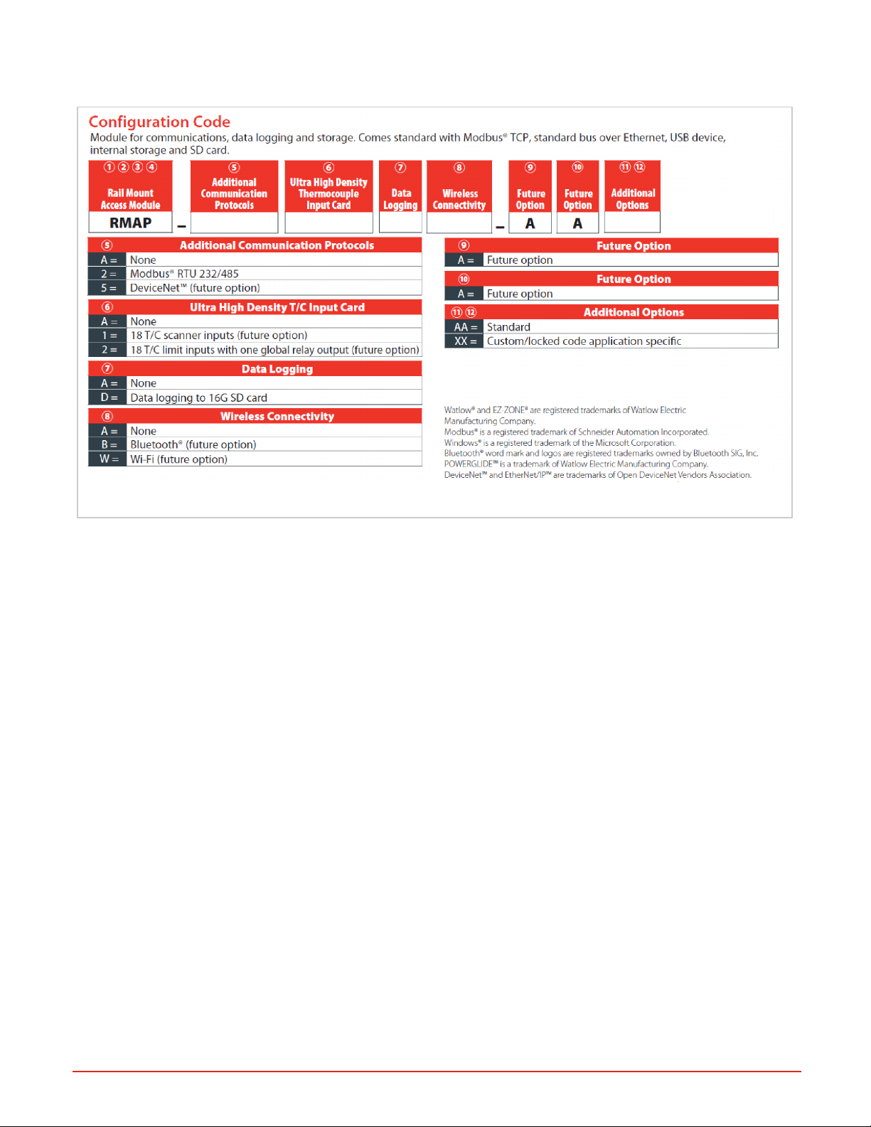
Ordering Part Numbers
Figure 1: RMA PLUS Configuration Codes for Ordering
Document #10-32813 Rev A; June 07, 2019
Page 8 of 69
Page 9
Chapter 2 | Mounting and Wiring
Mounting (DIN Rail or Chassis)
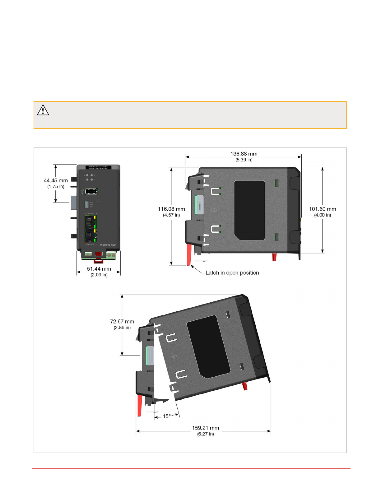
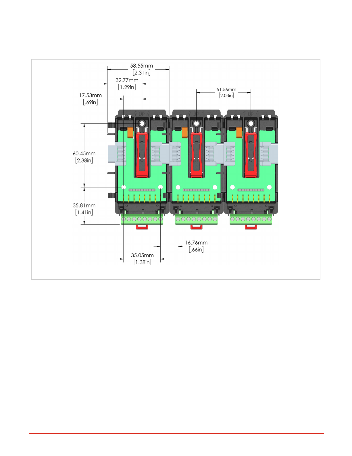
You can mount the RMA PLUS to a standard DINrail or mount to a panel with a #8 3/4" screw and torque to 10-15 in.-lb.
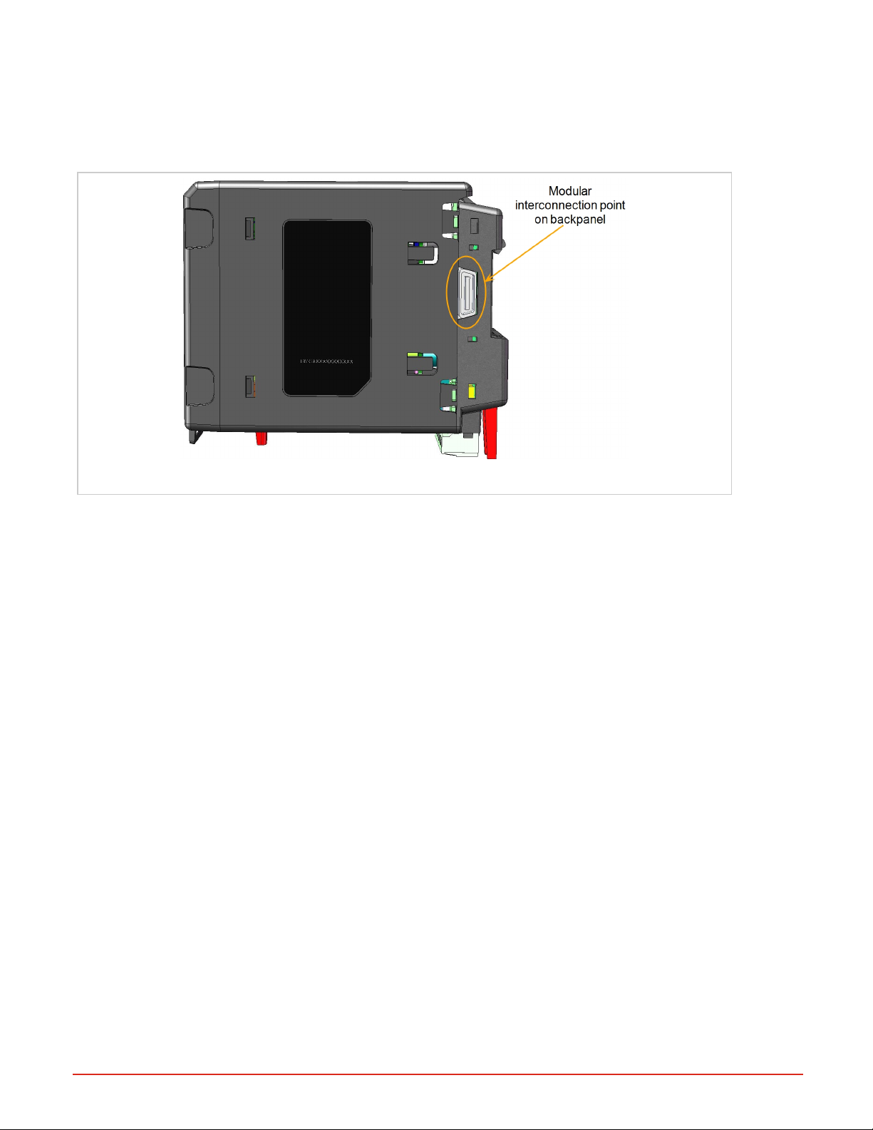
The RMA PLUS can be interconnected with other RM modules via the modular interconnection points on the back panel
of all EZ-ZONE units. See "Wiring Power and Communications" on the next page.
CAUTION: If you drop the product from 20” or higher when mounted on the X-axis, malfunction may
result.
Rail Mount
Document #10-32813 Rev A; June 07, 2019
Figure 2: Mounting Dimensions
Page 9 of 69
Page 10
Chassis Mount
With no DIN rail, mount the removable backplane to a panel using a #8 3/4 screw, no washers of any kind, and torque to
10-15 lbs. This illustrates the backplane dimensions and screw position of three modules mounted side by side.
Figure 3: Back Plane Dimensions (illustrating 3 connected units)
Wiring Power and Communications
The RMA PLUS module can be installed as a stand-alone module or interconnected with other RM modules on the DIN
rail via the standard EZ-ZONE modular interconnection point.
Slot C Power and Communications
Slot C on the bottom rear of the device provides connections for power, standard bus, and inter-module bus communications.
Low Power Input Requirements (same for all RM models)
l 20.4 to 30.8 VAC ~(ac)/ m (dc) 14VA
l 47 to 63Hz
l Controller module power consumption: 7 watts maximum
l 31 Watts maximum power for power supply part # 0847-0299-0000
l 60 Watts maximum power for power supply part # 0847-0300-0000
l 91 Watts maximum power for power supply part # 0847-0301-0000
l Class 2 or safety extra low voltage (SELV) power source required to comply with UL® standards
Document #10-32813 Rev A; June 07, 2019
Page 10 of 69
Page 11
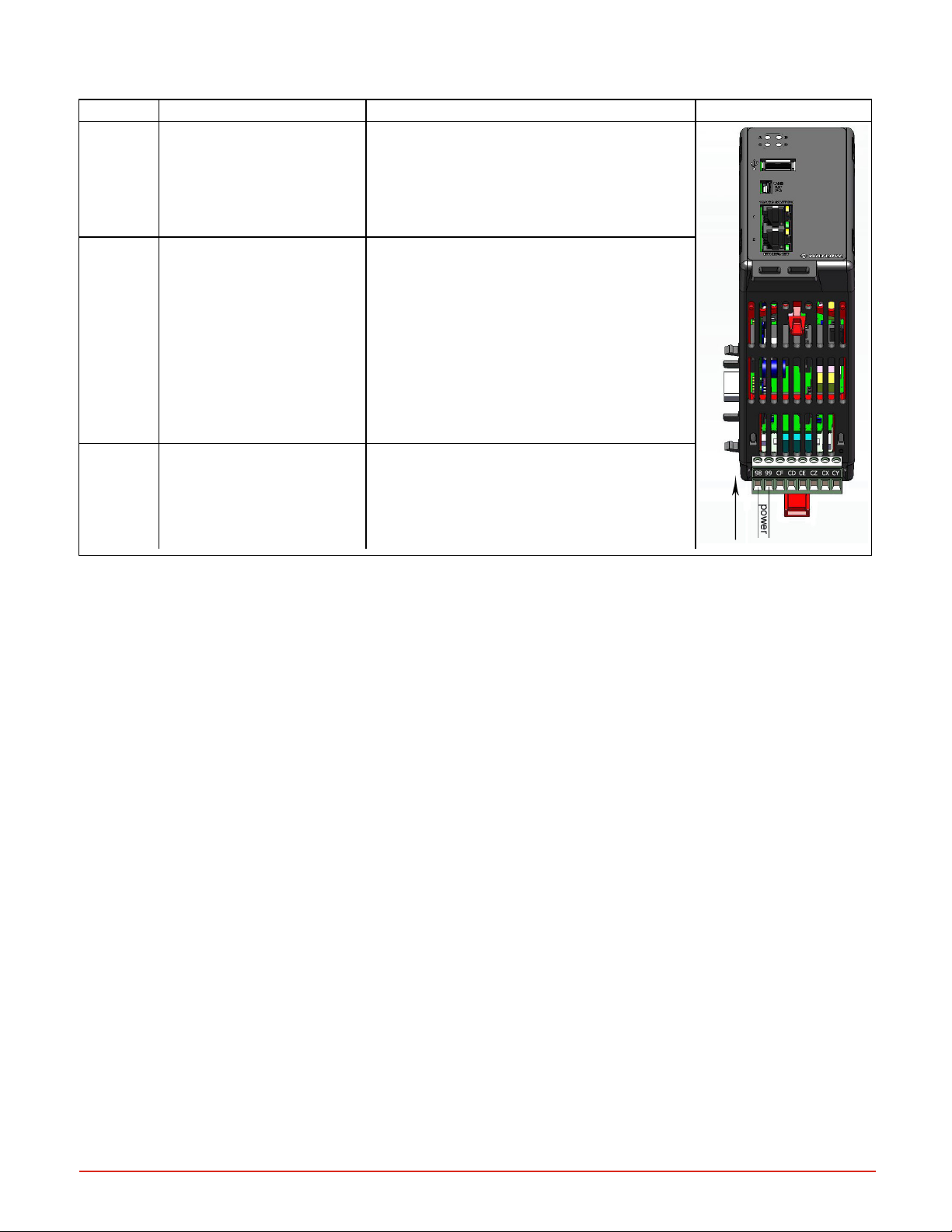
Power and Communication Slots
Slot Terminal Function Configuration Power In
98, 99
Power input AC or DC+ Only needed on one module; shared on back-
plane
CF, CD,CEStandard bus EIA-485 Com-
mon
Standard bus EIA-485 T-/R-(A)
Standard bus EIA-485 T+/T+
(B)
CZ, CX, CY Intermodule bus Wire for split-rail configurations
EIA-485 connection for EZ-ZONE
CONFIGURATOR
Earth Ground for USBH and USBD Connectors
The USB Host and USB D connector bodies are grounded to earth using the wire trap on the bottom of the case. To
ground the connectors, insert a ground wire into the trap from the case bottom. Use 18 – 26 AWG Solid or Stranded,
Trim Length 3.5 ± 0.5mm (0.138 ± .02”). This earth ground is not connected to the power.
Document #10-32813 Rev A; June 07, 2019
Page 11 of 69
Page 12
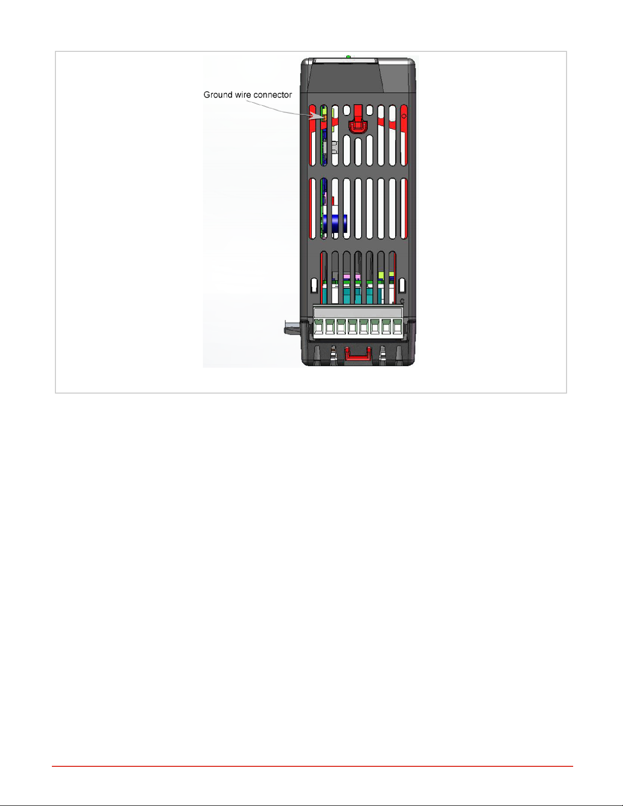
Figure 4: Ground Wire Connection Point
RMAPLUS Communications Options
RMAP-AAXX-XXXX: Standard Options Model
RMAP-AAXX-XXXX: stand-alone RMA PLUS in slot A/D is the basic model with Ethernet, USBonly. You can use
either or both Ethernet jacks simultaneously for any downstream or upstream.
Document #10-32813 Rev A; June 07, 2019
Page 12 of 69
Page 13
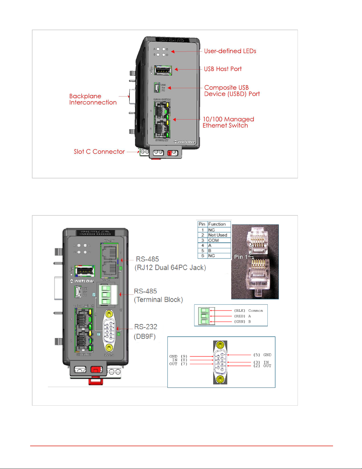
Figure 5: RMAP-Axxx-xxxx Models
RMA PLUS with Communication Options RS-232/RS-485
RMAP-2XXX-XXXX: models include current communication options: RS-232 / RS-485 module in slot B/E. Note that
the 6 and 7 Ethernet ports are separate, so you need to specify the port when configuring Modbus® RTU.
Document #10-32813 Rev A; June 07, 2019
Figure 6: RMAP-2XXX-XXXX
Page 13 of 69
Page 14
System Wiring
The RMA PLUS module can be interconnected with other RM modules on the DIN rail via the standard EZ-ZONE modular interconnection point on the backplane, which is a standard feature on every device in the EZ-ZONE RM family.
You may run power and communications for the entire system of connected RM devices through the RMA PLUS.
Figure 7: Interconnection Point
Ground Wire Connection Point
Split Rail Power Needs
You may have a single power supply designated for two separate DIN rails with interconnected RM modules. When
designing your hardware layout for a split rail system, consider the available power supply and the loading effect of all
modules used.
Watlow provides three options for power supplies:
l 90-264VAC to 24VDC @ 31 watts (Part #: 0847- 0299-0000)
l 90-264VAC to 24VDC @ 60 watts (Part #: 0847- 0300-0000)
l 90-264VAC to 24VDC @ 91 watts (Part #: 0847- 0301-0000)
Note the maximum power for each individual module of 7 watts/14VA, and consider the total of all combined units when
planning power to your split rail system:
l RMCxxxxxxxxxxxx @ 7 watts / 14VA
l RMEx-xxxx-xxxx @ 7 watts / 14VA
l RMHx-xxxx-xxxx @ 7 watts / 14VA
l RMLx-xxxx-xxxx @ 7 watts / 14VA
l RMSx-xxxx-xxxx @ 7 watts / 14VA
Document #10-32813 Rev A; June 07, 2019
Page 14 of 69
Page 15
Chapter 3 | Getting Started
About the USB Drives
Files necessary for configuration, operations, and data logging are loaded onto three drives on your RMA PLUS. The
specific contents of these files vary per model number and features purchased, but all RMAPLUS devices contain
these three drives:
l NOR Flash drive – to configure internal settings of the RMA
l Micro SD drive – user data i.e. data logs and supporting utilities
l RAM Disk drive – dynamic data for system confirmation, i.e. network status
You may connect your RMAPLUS to your PC with a mini-B USBcable and access the files on these drives to configure your RMA PLUS only after you install the USBDrivers. (If you have previously installed Watlow USB drivers
using COMPOSER, you do not need to reinstall the drivers).
Installing Device Drivers
You must install Watlow USB device drivers before using the Micro SD, NORFLASH, and RAM Disk drives included
with your RMA PLUS. (If you already use a Watlow RM product and have Watlow USB drivers installed, you do not
need to reinstall the drivers and may proceed to Configuration).
1. Connect your PC to the mini USB Device connector on the RMA PLUS. Windows will attempt to install the drivers,
but the RMA PLUS device driver will not be found.
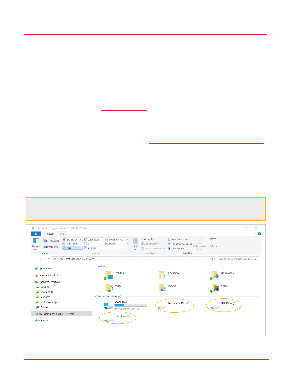
2. Open My Computer (Windows key + ‘E’) and look under the “Devices and Drives” group. With your RMA PLUS connected via the USB cable, you should see its three drives listed. In this image, the drives are labeled with letters E, D,
and F, but your computer may have different letters for the drives.
If the drives do not appear, check the "View" settings of Windows Explorer. Click the View tab of Windows
Explorer, then make sure "Hidden Items" is checked, and/or uncheck "Hide empty drives in the com-
puter folder" (if using Windows 7) or uncheck "Hide empty drives" (if using Windows 10).
Figure 8: Drives Not Mounted to PC, Viewed in Windows Explorer
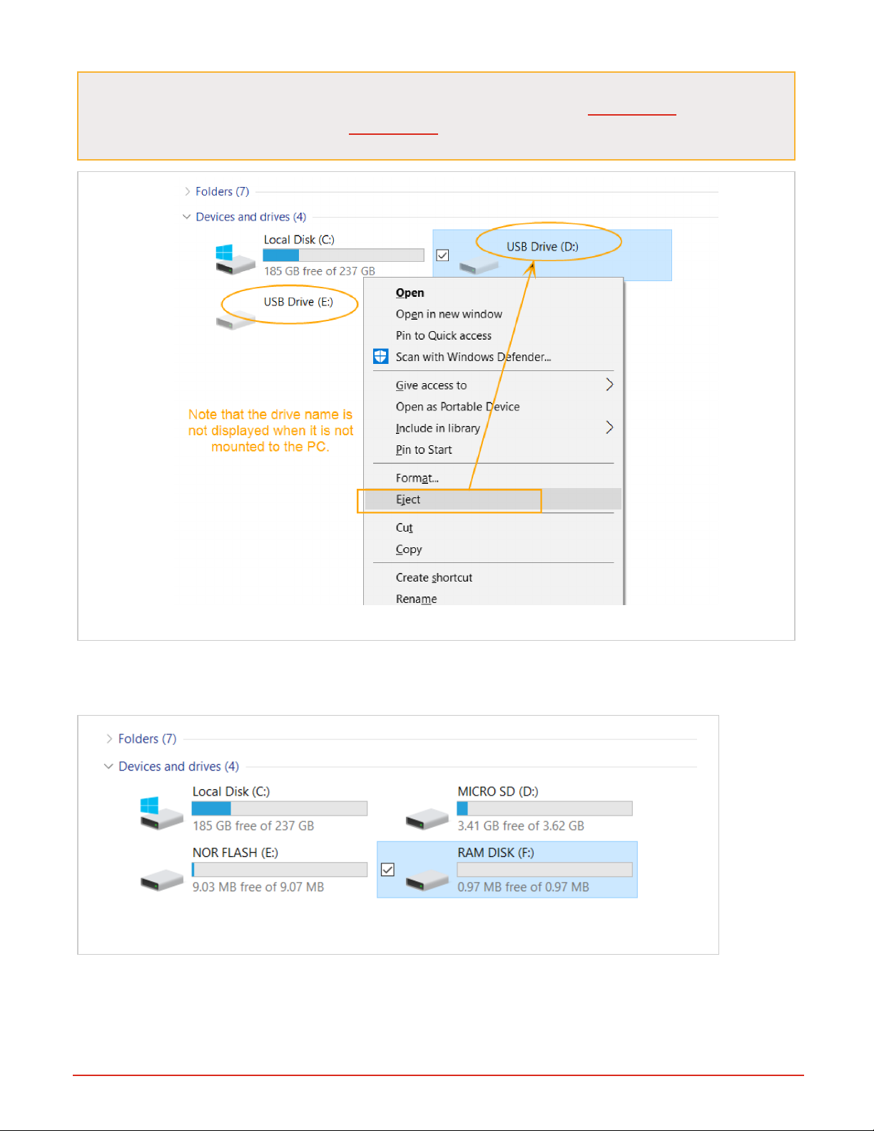
3. Right-click each drive and select the “Eject” option. "Eject" is used to mount and unmount the drives from the PC.
Document #10-32813 Rev A; June 07, 2019
Page 15 of 69
Page 16
NOTE: There is an issue with certain versions of Windows 10 OS where you cannot eject one drive
without the other drives being affected. If you notice thishappening, use the CSV Creator tool to mount
and unmount the drives. You'll be using CSV Creator to configure the drives, and it has mount/unmount
buttons for each of the drives in it.
Figure 9: Use the Eject menu option to mount a drive to the PC
When the drive is mounted to the PC, you'll see the name of the drive recognized, and the PC will have exclusive control of the drives. In the image below, all three drives have been "ejected" or mounted to the PC. You can now see the
drive names for each: MICRO SD; NOR FLASH; and RAM DISK.
Figure 10: Drives Mounted to PC, Viewed in Windows Explorer
l Note: If your computer is set up to automatically open the drive to view the directories on the drive, you may close it.
It is not necessary at this time to view any files on the drives
4. After you have mounted all three drives, from your computer’s start menu, open the Device Manager.
Document #10-32813 Rev A; June 07, 2019
Page 16 of 69
Page 17
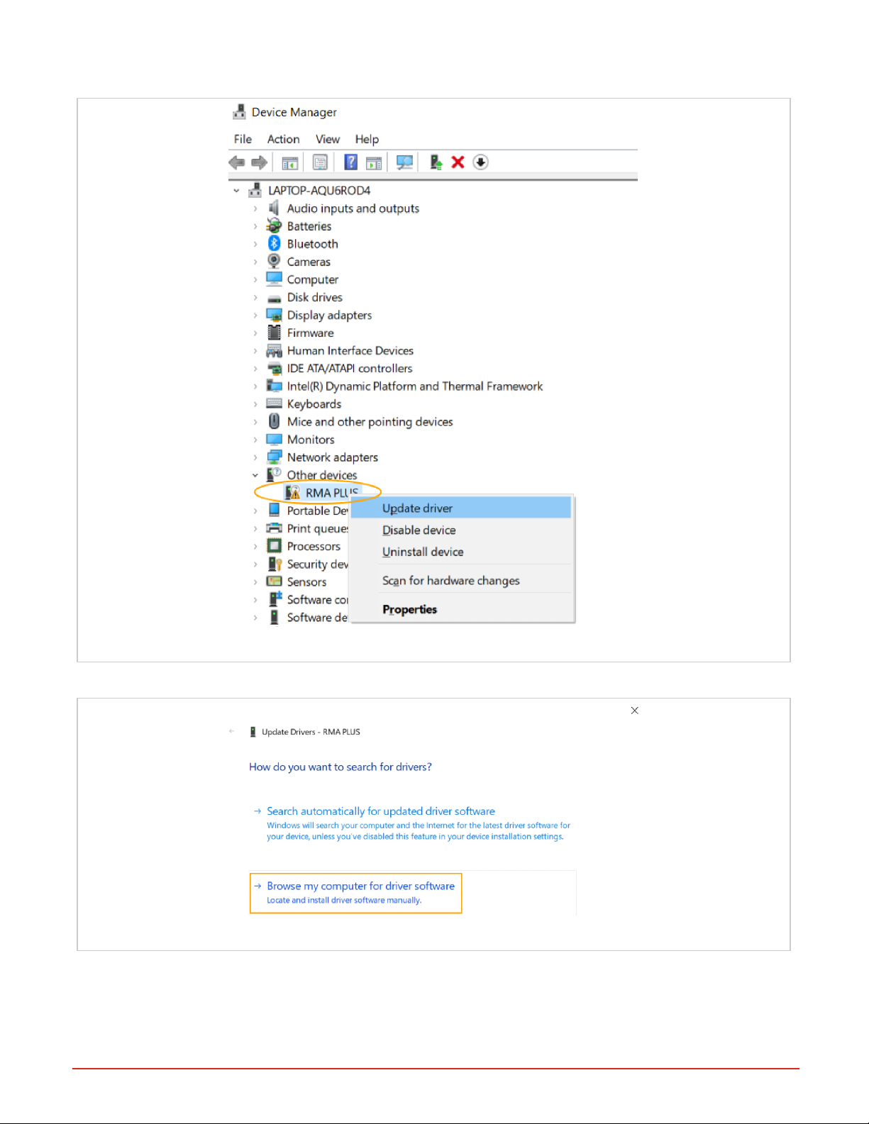
5. Right-click “RMA PLUS” under “Other devices” and then select Update Driver Software.
Figure 11: Update Driver Software via Windows Device Manager
6. Select “Browse my computer for driver software”.
Figure 12: Choose "Browse my computer for driver software."
7. Browse to the drive labeled “MICRO SD” and press the “OK” button
Document #10-32813 Rev A; June 07, 2019
Page 17 of 69
Page 18
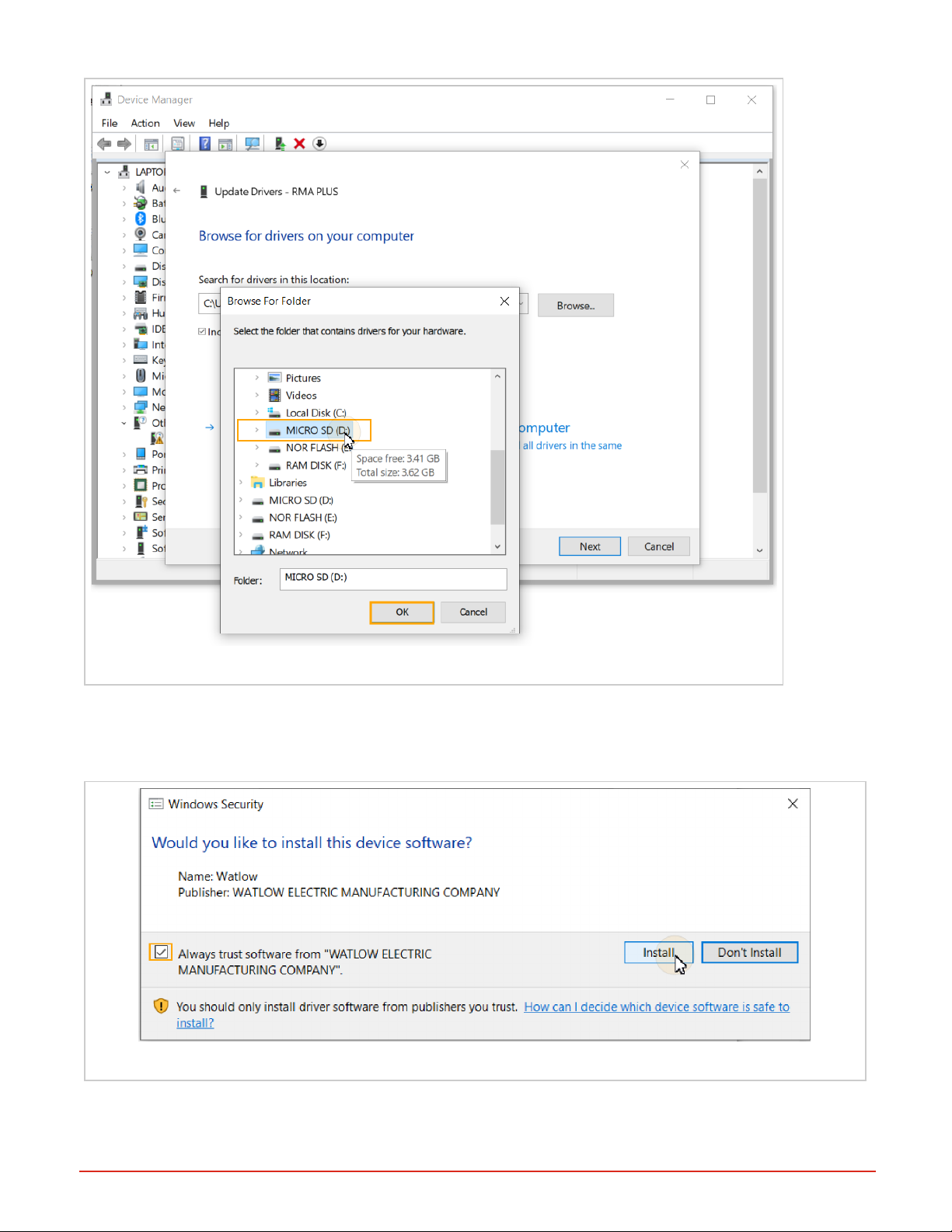
Figure 13: Browse to the MICROSD drive
8. Ensure “Include subfolders” is checked and press the “Next” button.
l Note that the full path to the driver in this example is “E:\Software\S19 Flashloader\USB Drivers”.
9. Select “Install."
Figure 14: Press the Install button
The following is displayed upon successfully installing the driver.
Document #10-32813 Rev A; June 07, 2019
Page 18 of 69
Page 19
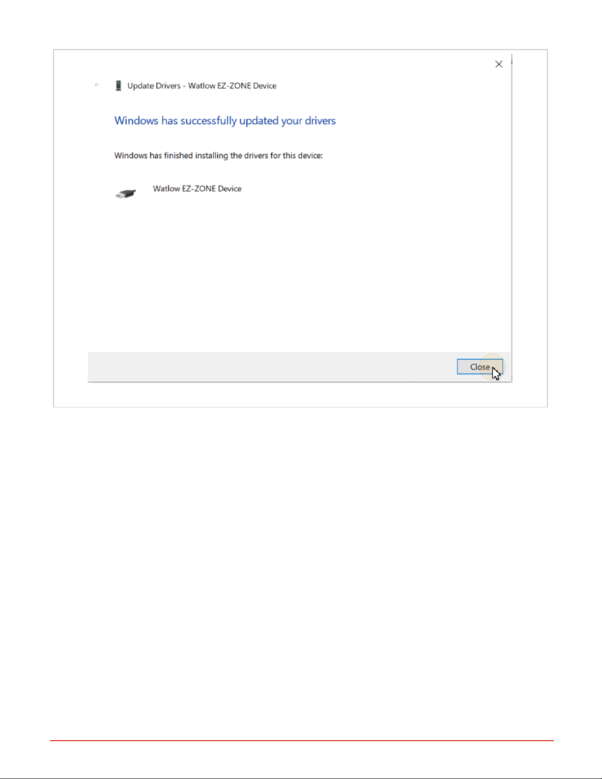
Figure 15: Device Driver Install Success Message
10. Return to Windows Explorer, select the drive, right-click, and select “Eject” to unmount the drive from the PC. This
returns exclusive control of the drive to the firmware.
Repeat the above steps for each drive on the RMA PLUS.
Accessing and Working with Files on the USBDrives
1. Connect the Mini-B USB cable to the RMA PLUS.
2. Open My Computer (Windows key + ‘E’) and look under the “Devices and Drives” group. The remov-
able drives are shown here. Note that the drive letter and order may vary by computer.
3. Right-clickeach drive and select Eject to give your PC exclusive access to the drives. This sends a
start/stop command to the device. When the PC mounts a drive, all firmware services that use that
drive are suspended.
Document #10-32813 Rev A; June 07, 2019
Page 19 of 69
Page 20
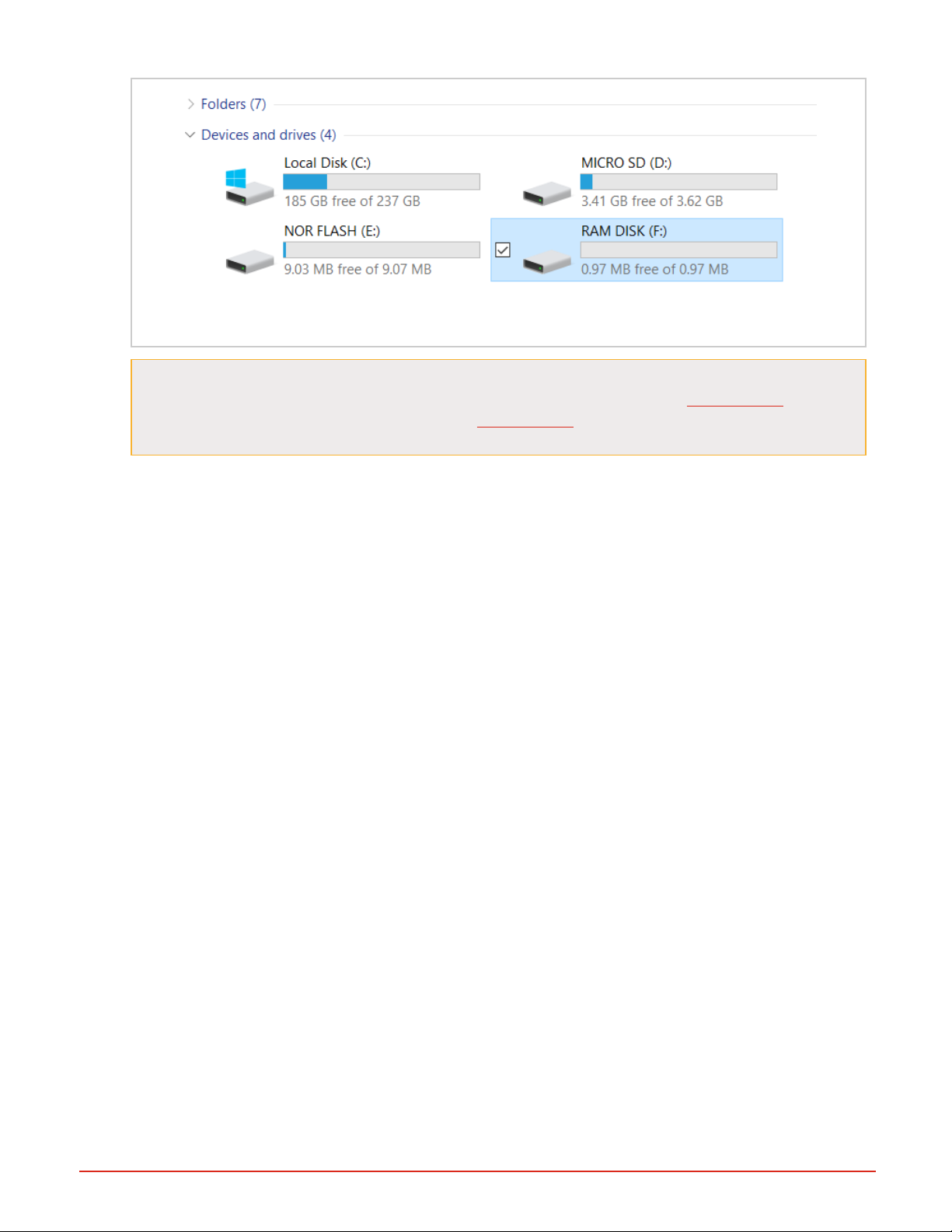
Figure 16: Windows Devices View: All Drives Mounted to the PC
NOTE: There is an issue with some versions of Windows 10 OS where you cannot eject one drive
without the other drives being affected. If you notice thishappening, use the CSV Creator tool to
mount and unmount the drives. You'll be using CSV Creator to configure the drives, and it has
mount/unmount buttons for each of the drives in it.
l Do not disconnect the USBcable without first ejecting or unmounting the drives via CSVCreator. If the USB
cable is disconnected, the RMA PLUS will regain access to the drives after a several second timeout, but
removing the USB cable while the drives are mounted on the PC could result in corruption.
l When a drive is mounted to your PC, the PC has exclusive access to that drive. All firmware features that
require the drive are suspended. The default drive state is ejected (unmounted) to prevent unintentional suspension of firmware services.
l Changes made to a drive take effect after the RMA PLUS regains full control of the drive.
l LEDs on the unit change to indicate the drive state. GREEN = RMA PLUS has access to the drive.
ORANGE = RMA PLUS has access, and a USB cable is connected. RED = RMA PLUS has no access to
the drive because it is mounted to the PC via the USB port.
4. After you finish working with a drive, close all files and folders and press “Eject ” to unmount the drive from the
PC. When all drives are unmounted, you may safely remove the USB cable.
l Note that the drive names are no longer displayed on your Explorer window, and the LEDs change from
orange to green about five seconds after the cable is removed.
Document #10-32813 Rev A; June 07, 2019
Page 20 of 69
Page 21
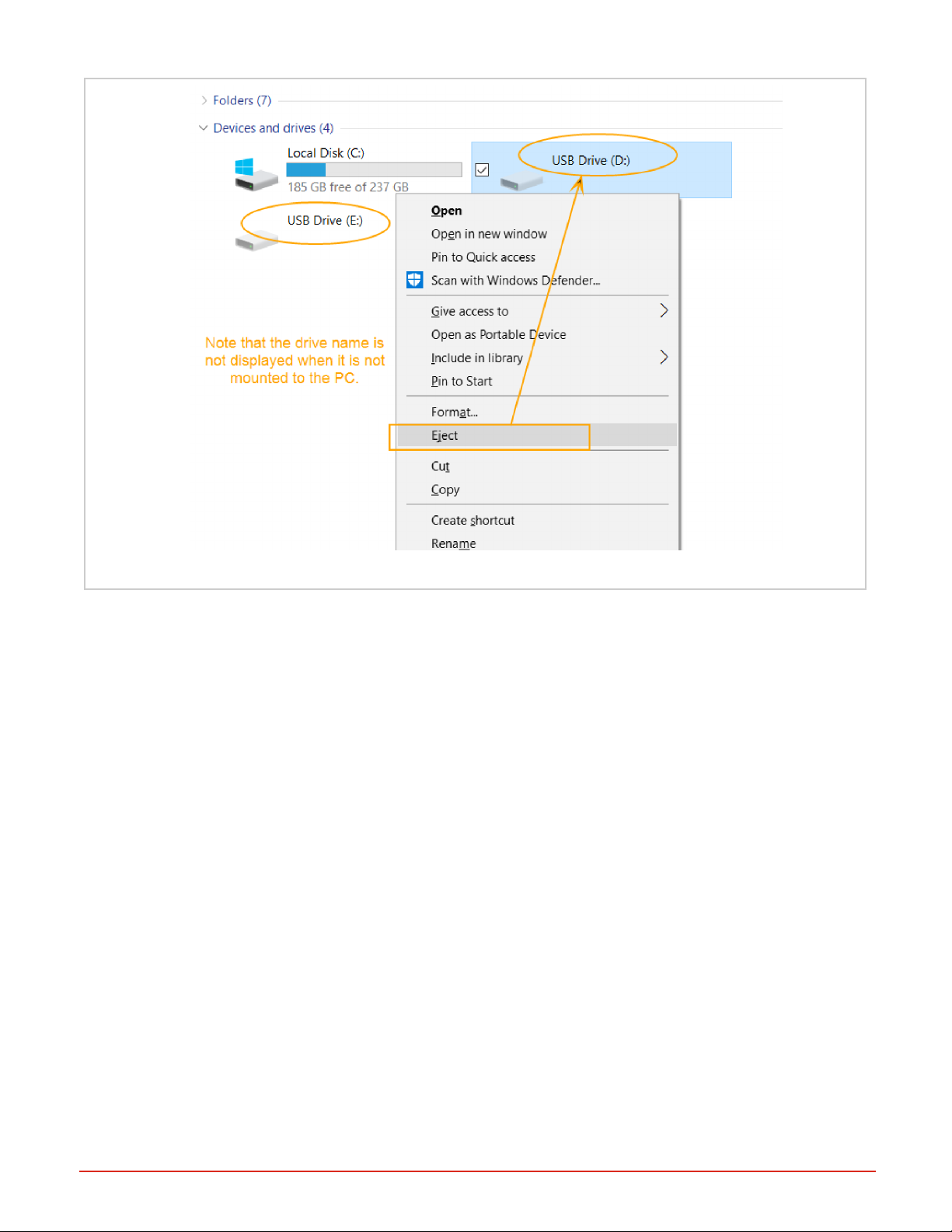
Figure 17: Eject the Drives to Unmount from PC
Document #10-32813 Rev A; June 07, 2019
Page 21 of 69
Page 22

Chapter 4 | Configuration
Overview
Product features like data logging, Modbus, etc. are configured via .csv files on the drives on your RMA PLUS. When
you connect to the device via USB, you can access these three drives: MICRO SD, NOR FLASH, and RAM DISK,
which each contain files for configuration or operation of the RMA PLUS. For configuration help, see CSVCreator.
NOTE: CSVCreator is provided to help you edit the default configurations over a USB connection. (Files can be
read over Ethernet, but not written). We recommend that you do not manually edit the files, to prevent corruption of
data. Configuration files are only read upon initialization. You must reset the RMA PLUS for a change to take effect.
Configuration File Formats
Each row in the file constitutes a record. Record elements are separated by commas. Header rows indicate what is in
the column below, but header rows and empty rows are ignored by the parser.
This example shows the data for a Modbus® TCP configuration file. Field bus or application information is in the first
column. The bus number follows and dictates the remainder of the record. Busses 1 and 2 are standard bus records with
the same format. Bus 0 records are ignored by the parser to disable a record without deleting it. Any trailing information
is disregarded.
Modbus® TCP Register Config Example
Register Bus Seg ment Zone Class Instance Member Refresh
Count
0 0 0 0 1 1 1 0 DEV 1 Hardware ID
2 1 0 1 1 1 1 0 DEV 1 Hardware ID
4 2 4 1 1 1 1 0 DEV 1 Hardware ID
The setup configuration file, setup.csv is found at the root of the NOR FLASH drive at nor:\Setup.csv. This is the first
file read by the RMA PLUS upon reset. Each line is a record of a key, value pair. The key is a string value must match a
key string in the firmware or it is disregarded. The value data type is specified in the setup key.
Setup.csv Default Values
Key Value
EventLog ram:\EventLog.txt
SysCfg nor:\Gateway\SysCfg.csv
ModbusTCP nor:\Gateway\ModbusTcp.csv
ModbusRtu6 nor:\Gateway\ModbusRtu6.csv
ModbusRtu7 nor:\Gateway\ModbusRtu7.csv
UART7 0
DataLog nor:\Gateway\DataLog.csv
LogIntervalSec 5
Document #10-32813 Rev A; June 07, 2019
Page 22 of 69
Page 23

Configure Ethernet with Dashboard
Before you begin
If you do not already have Dashboard on your machine, you will find it on the SD: drive of your RMA PLUS. Connect a
Mini-B USB cable to the RMA PLUS, eject the SD: drive to mount it to your PC, open the Software folder, open Dashboard folder, and then extract the Dashboard .zip files to a new directory on your PC. You may then launch Dashboard.exe from there.
1. Launch Dashboard. The discovered RMA PLUS should be under the “USB Devices” tree node.
Figure 18: Dashboard: USBDevices in Tree Node
2. Expand the RMA PLUS to see basic device information.
Figure 19: RMA PLUSExpanded in Tree Node
3. Drag and drop the RMA PLUS tree node onto the Device Data pane to upload all parameters.
Figure 20: Dashboard: Drag Device into Data Pane
Document #10-32813 Rev A; June 07, 2019
Page 23 of 69
Page 24

Dashboard displays the progress while it discovers all parameters. If the progress window does not automatically closs,
press the “Close Now” button after the transfer statuses read "complete."
5. On the newly discovered device tab, expand the Ethernet and Ethernet 2 tree nodes.
Figure 21: Dashboard: Ethernet in Data Pane
6. Change the following members as necessary:
Ethernet 70 (0x46) Instance 2
Member ID Member Name Data Type Access NV Min Max Default Comments
16 0x10 IP Address Mode ENUM16 RW F 1284
1281: DHCP
1284: FIXED
55 0x37 Statis IP Address String STRING RW F 192.168.0.100
56 0x38 Statis IPSubnet Mask String STRING RW F 255.255.255.0
57 0x39 Static IP Default Gateway String STRING RW F 192.168.0.1
NOTE: We recommend using static IP addressing and a private network for your system.
For each desired change…
l Double-click the member in the tree view.
l Enter a new value in the “Value“field.
l Press the “Write To Grid and Device” button.
Document #10-32813 Rev A; June 07, 2019
Page 24 of 69
Page 25

Figure 22: Dashboard: Edit Static IP Address
7. Wait at least three seconds for non-volatile data to save.
8. Select the Settings tab.
9. Set Use Ethernet to True and press the Save Settings button.
Figure 23: Dashboard: Set Ethernet to True
10. Close Dashboard and remove the USB cable from the RMA PLUS.
11. Reset the RMA PLUS.
12. Connect an Ethernet cable from your PC to either port of the RMA PLUS.
NOTE: The PC’s network interface configuration is outside the scope of this document. It should be configured for a static IP address on the same subnet taking care to avoid addresses 192.168.0.xxx (where
xxx = 1, 100 or 255 for the last octet in this example). NetBIOS is also recommended.
13. Launch Dashboard to view the RMA PLUS and any devices connected to the high-speed standard bus network
under the “Ethernet Devices” tree node. Expand the RMA PLUS to see device information including the Ethernet
address.
Document #10-32813 Rev A; June 07, 2019
Page 25 of 69
Page 26

Configuring RMA PLUS with CSV Creator
Overview
CSV Creator is used to configure Modbus, data logging, and other settings on an installed RMA PLUS and its connected devices.
CSV Creator discovers the configuration parameters on your installed RMA PLUS and connected devices to ensure
that the created data log and Modbus® configurations are valid for your RMAPLUS and any connected devices. This
discovery is accomplished via USB or Ethernet connection.Note that with a USB connection your PC can mount drives
to the RMA PLUS, allowing you to save your configuration files directly to the device. If you connect via Ethernet, you
will have to save the configuration files to your PC rather than to the device itself.
Initial Setup
You will find the newest version of CSVCreator on www.watlow.com.
1.
Download the CSVCreator .zip file from watlow.com onto your PC and then extract the files to a directory on
your PC.
2.
Open the newly created CsvCreator directory and double-click CsvCreator.exe to open the application.
3.
Note that the On-Line Params tab is shown by default and displays your discovered devices.
l
If your devices are not listed in the On-line Params tab, click the Settings tab to set USB and/or Ethernet val-
ues to True, then close and restart CSVCreator.
Figure 24: Online Parameters Tab Open
4.
Select Serial connection options:
l
If you'll use a serial connection, click the Settings tab and set Use Serial to true and select the serial port to
use.
l
If you need to change the serial port, disable it, save the settings, restart CSVCreator, and then select a new
serial port.
l
If you are not using the serial port, disable the serial port, save settings, and then restart the application. If the
serial port is enabled but not being used, your initial device discovery will be slow.
5.
After your settings are configured, click the Save Settings button, shut down, and restart CSV Creator.
Document #10-32813 Rev A; June 07, 2019
Page 26 of 69
Page 27

NOTE: When CSV Creator is initially invoked, and every time the RMA PLUS is reset, CSV Creator will discover the
RMA PLUS and all devices connected to it via the configured communications interfaces. Thus, to discover new
devices, restart CSVCreator, or click the Reset the RMAPLUS button to reset the RMA PLUS and restart
CSVCreator. All data in the table view is removed during a reset operation, so be sure to save any in-progress files
before a reset.
Figure 25: CSV Creator Settings Tab
General Usage of CSVCreator
Device Tree
The tree on the left shows the list of discovered devices associated with the RMA PLUS, and indicates indicates which
interface the device is discovered on, with a “via USB” or “via Ethernet” label after the device part number. Hover over
the device name in the tree to see information related to the device zone number and the IP address of the device if it is
on Ethernet. Hovering over an instance field displays the initial or current value read from the control for that parameter.
Each time you hover over or move off of a parameter, the parameter value is refreshed. If the parameter is an enumeration, the enumeration text is shown in addition to the numeric value. Showing the value helps identify correct parameters.
Location Dropdown
The location dropdown above the device tree indicates a specific connection point to an RMA PLUS and all connected
devices. If you connect multiple interfaces to the same RMA PLUS, you will get multiple locations for the same device.
The location pulldown ensures that you can differentiate which set of devices are attached to a single location, i.e. RMA
PLUS via a single interface. Having multiple RMA PLUS devices connected during configuration is not recommended.
File Type Dropdown
Select the file type you wish to configure using the dropdown menu above the data table. Always save the table data to
a file or clear the data from the table before switching file types. CSV Creator will not allow you to change file types until
you either save or clear the data, to make sure data is not lost.
Drive Status Buttons
A status bar above the data table indicates the mounted or unmounted state of each of the drives on the RMA PLUS.
• Yellow = all drives are unmounted from the PC
Document #10-32813 Rev A; June 07, 2019
Page 27 of 69
Page 28

• Green = one or more of the drives is mounted to the PC. Text on the bar shows which drives are mounted, and indicates the drive letter given to the drive by your PC.
Individual yellow or green color coded buttons next to this status bar may be used to mount or unmount each drive.
The NOR Flash drive must be mounted in order to save files to it. When the NOR Flash drive is mounted to the PC, the
Sort and Save button is directed to the NOR FLASH drive. When the NOR Flash drive is unmounted, the Sort and
Save function is directed to the PC. After selecting Sort and Save button you can change the path and filename in the
save dialog.
Figure 26: CSV Creator UI - Mount Drive Buttons
Saving Configuration Files
You may save files to the NORFLASHdrive of the RMA PLUS, or to your PC, or both. To save files to the RMA PLUS
you must have a USBconnection and the device must be mounted to the PC. To save a backup copy of the configuration files to your PC, unmount the NORFlash drive, select Sort and Save to the PC, and choose the desired
path, or use Windows File Explorer to copy the file to or from the RMA PLUS.
Configuring Modbus® Registers
CSV Creator allows the user to build a Modbus® configuration file by selecting File Type “Modbus® TCP”, “Modbus®
RTU 6”, or “Modbus® RTU 7”. These settings are stored in a file called “ModbusTcp.csv”, “ModbusRTU6.csv”, or “ModbusRTU7.csv” on the “NOR FLASH” drive of the RMA PLUS. In order to configure Modbus® TCP, parameters for the
RMA PLUS, and any slave devices, using user-assigned Modbus® register addresses, the default File Type is used
(See File Type pulldown menu). The menu also contains options to configure either of the Modbus® RTU interfaces via
different files on the RMA PLUS. The application is initially setup to configure Modbus® TCP via the File Type pulldown
menu, as shown in the image below.
Selecting Parameters for Modbus® and Data Logging
Use the device tree on the left side to view the classes, members, and instances available for Modbus® and data logging configurations. Configuration parameters are read directly from the devices.
You may select an entire class (including its members and instances) by dragging the item from the device tree into the
data table area on the right side of the screen, or by selecting the class name and clicking the space bar. You may likewise select all instances of one member by dragging the member name into the data table or selecting the member
name and pressing the space bar. To add a single instance to the table, drag the instance over, or select it and press the
space bar.
Document #10-32813 Rev A; June 07, 2019
Page 28 of 69
Page 29

Some parameters have performance advantages when being read from the devices. These parameters have a green
background when displayed in the tree and a tooltip that says “Producer.”
Figure 27: Modbus® TCPand Data Logging Example
Modbus® Default Register Addressing
By default, register addresses are automatically incremented as items are added to the table. You may override the
register addressing by typing a new address. To change the register in a row or group of rows, use the leftmost Row
Select column to select the desired rows. (To select multiple rows, select the first row in the group and drag down the
Row Select column, or hold the shift key while you select all the rows).
"Delete Selected Rows" is a permanent deletion
l
"Renumber Selected Rows" is used with a group of contiguous rows and renumbers the selected rows, starting with
l
the register address of the first selected row.
“Add Separator Below Current Row” allows you to add a separator to the table view for readability.
l
If there is duplicate data in the register column in the Modbus® files, the RMA PLUS will use the first occurrence.
Note that the RMA PLUS requires the Modbus® files to be sorted by register address (Register column), so
CSVCreator sorts the rows by register addresses upon saving. You may also manually sort the rows using the Sort button. These Modbus® configuration files must always contain incrementing Modbus® configuration data for proper functioning of the RMA PLUS. (This sorting functionality is disabled for other file types that do not require sorted data).
All the data to the right of the Description column will only be available upon initial load of the parameters, and will not be
saved to the configuration file, to minimize file size and improve performance. When the file is saved or reopened, these
columns will be blank, as the data is not saved to the files.
Document #10-32813 Rev A; June 07, 2019
Page 29 of 69
Page 30

Figure 28: Modbus® TCPAddress Register
Legacy Modbus® Register Addressing
To reuse existing Modbus® applications, select the Use Device Addresses option in the tool bar above the data table,
then restart the application. Once this is done, the tree view on the left side of the screen will show the legacy registers
of the connected devices to the right of the instance number.
This mode extracts the legacy register map from each control and adds the legacy register to the file, instead of just
incrementing the Modbus® register as items are added to the table. If the product (RMC, RME) has more than one set of
Modbus® maps, be sure to configure the product with the correct map prior to starting the CSV Creator application. This
will allow the CSV Creator application to pull the intended legacy Modbus® map from the control. The legacy register
addressing mode will persist between application executions, so you only need to change the setting once.
For non-legacy devices, or where the legacy decoder information is not found, the application will insert the new parameters as the next available location in the current list of parameters in the table. In the event of any duplicate registers
(Register column), in the Modbus® files, the RMA PLUS will use the first occurrence in the file.
Document #10-32813 Rev A; June 07, 2019
Figure 29: Using Device Addresses
Page 30 of 69
Page 31

System Configuration Settings
System settings are stored in the Setup.csv file on the NOR FLASH drive, which you can view in CSVCreator. To configure these system settings:
1.
Clear or save any previous data shown in the data table.
Figure 30: Clear Data Button
2.
Select Setup from the File Type dropdown menu.
Figure 31: Select Setup from the File Type Menu
3. If it is not already mounted, mount the NORFlash Drive to your PC using the Mount NOR button. (When the
device is mounted, this button will be green. The status bar will also be green and will state the drive letter represents the NOR FLASH drive on the PC).
4. Select the Load from RMAPLUS button.
Figure 32: Load from RMAPLUS Button
Note: Do not corrupt this setup.csv file or your RMA PLUS will not operate correctly.
Data Log Configuration
CSV Creator may be used to configure data logging for the RMA PLUS. The parameter selection available is the same
as shown for the Modbus® configurations above. Parameters for the RMA PLUS and all connected devices will be available for data logging. Like on the Modbus® table, all parameters to the right of the description column will only be shown
on the initial load of the parameters from the device, as they are not saved in the file.
Document #10-32813 Rev A; June 07, 2019
Page 31 of 69
Page 32

Figure 33: Data Logging Example
HTTPs Web Server Configuration
CSV Creator will pull a list of parameters from the RMA PLUS and connected devices so you can configure a read-only
web server in the RMA PLUS.
l
Select Https from the File Type pulldown.
l
Add the desired parameters to the grid by dragging them from the list on the left, in the same manner as used for the
other file types. A unique token will be generated by the application using the following information: zone, partial
class name, class number, parameter name, parameter number, and instance number, i.e. Z16Mat25OutputValue22I2 corresponds to zone 16, Math class 25, Parameter 22 "Output Value", Instance 2.
See HTTPs for more information about this feature.
Applying Configuration Changes to the RMA PLUS
For the RMA PLUS to accept and start using the changes to the files after they are written to the RMA PLUS’ internal
drives, the RMA PLUS either needs to be power cycled, or reset via the “Reset the RMA PLUS” button at the top of the
application. Save all files before pressing the reset button, as this button resets the RMA PLUS and restarts the
application, and you will lose any information not previously saved to either the RMA PLUS or your PC. You also need
to save the table data or clear the table prior to switching file types.
Data Types for Configuration Files
Data Type Value Description
UINT8 1 unsigned 8-bit integer
SINT8 2 signed 8-bit integer
UINT16 3 unsigned 16-bit integer
SINT16 4 signed 16-bit integer
UINT32 5 unsigned 32-bit integer
SINT32 6 signed 32-bit integer
ENUM8 7 enumeration (8-bit)
FLOAT 8 single-precision floating point
STRING 9 string
Document #10-32813 Rev A; June 07, 2019
Page 32 of 69
Page 33

Data Type Value Description
PARAM 12 parameter (C|M|I)
ENUM16 15 enumeration (16-bit)
Busses
The RMA PLUS must be a master on a given bus to acquire data. It is a master by default on standards bus 1 and 2. It
may optionally be a master on Modbus® RTU (bus 4 and 5) if configured by the user.
Bus 0: Nothing
Disregard entry. This tells the file parser to disregard this entry / record.
Bus 1: Inter-Module Bus
This is the preferred bus for accessing data. It is the fastest and most efficient bus available. Any EZ-ZONE RM (9+)
module may be connected to this bus.
IMPORTANT: Do not attempt to access the Subroutine class (0x05) or Profile Step class (0x15) from the intermodule
bus. This will cause unpredictable results due to timing restrictions.
Bus 2: Standard Bus
This bus is used to access legacy EZ-ZONE devices that do not support intermodule bus: EZ-ZONE RM, PM (15+). Do
not use this bus if bus 1 is available. NOTE: The EZ-ZONE ST and RUI do not currently implement the required services necessary to talk to the RMA PLUS.
Bus 4, 5: Modbus® RTU Master
If the model number is RMAP-2AXX-XXXX, then the device will have a card in the adjacent slot that provides two additional serial ports for connection to Modbus® RTU devices via RS-232 or RS-485. Bus 4 goes with Modbus® instance
6. Bus 5 goes with Modbus® instance 7.
Producer / Consumer Data
Producer / consumer data is used on intermodule bus. This subscription service allows devices (zones) to share data
with their network peers. It is analogous to multicast traffic in Ethernet in that it is produced by devices at regular intervals and heard by all on the network, but only devices that subscribe to published data points consume these received
frames.This is the most efficient way to obtain data in the system and reduces the overhead for request frames,
queuing, data packing, etc.
This table documents the relationship between the source name (Text ID) and intermodule busaddress (Class ID, Member ID) for all producers. Produced data points are outputs of software objects (function blocks).
Producer/Consumer Data Subscription Reference
A (analog) / D
Text ID Class ID Member ID
61 None A/D
142 Analog Input 4 0x04 22 0x16 A
22 Current 15 0x0F 1 0x01 A
(digital)
179 Current Read 15 0x0F 7 0x07 A
161 Cool Power 8 0x08 14 0x0E A
160 Heat Power 8 0x08 11 0x0B A
Document #10-32813 Rev A; June 07, 2019
Page 33 of 69
Page 34

73 Power 8 0x08 33 0x21 A
238 Linearization 34 0x22 7 0x07 A
240 Math 25 0x19 22 0x16 A
241 Process Value 26 0x1A 22 0x16 A
242 Set Point Closed 7 0x07 7 0x07 A
243 Set Point Open 7 0x07 8 0x08 A
245 Variable 2 0x02 4 0x04 A/D
6 Alarm 9 0x09 24 0x18 D
230 Compare 28 0x1C 10 0x0A D
231 Counter 30 0x1E 10 0x0A D
1142 Digital I/O 6 0x06 11 0x0B D
233 Profile Event Out 22 0x16 14 0x0E A/D
234 Profile Event Out 22 0x16 15 0x0F A/D
235 Profile Event Out 22 0x16 16 0x10 A/D
236 Profile Event Out 22 0x16 17 0x11 A/D
247 Profile Event Out 22 0x16 18 0x12 A/D
248 Profile Event Out 22 0x16 19 0x13 A/D
249 Profile Event Out 22 0x16 20 0x14 A/D
250 Profile Event Out 22 0x16 21 0x15 A/D
1001 Function Key 3 0x03 24 0x18 D
239 Logic 27 0x1B 34 0x22 D
244 Timer 31 0x1F 10 0x0A D
1532 Special Function 35 0x23 10 0x0A A/D
1533 Special Function 35 0x23 12 0x0C D
1534 Special Function 35 0x23 14 0x0E D
1535 Special Function 35 0x23 16 0x10 D
126 Limit 12 0x0C 7 0x07 D
1577 Time of Day 36 0x24 1 0x01 A
1578 Day of Week 36 0x24 2 0x02 A
1696 Module Limit 101 0x65 10 0x0A D
1619 Produced Set Point 1 79 0x4F 38 0x26 A
1620 Produced Set Point 2 79 0x4F 39 0x27 A
1621 Produced Set Point 3 79 0x4F 40 0x28 A
1622 Produced Set Point 4 79 0x4F 41 0x29 A
184 Heater Error 15 0x0F 38 0x26 D
1697 Wattage 29 0x1D 14 0x0E A
1699 Load Voltage 29 0x1D 13 0x0D A
1183 Load Resistance 29 0x1D 16 0x10 A
Document #10-32813 Rev A; June 07, 2019
Page 34 of 69
Page 35

142 Analog Input 55 0x37 4 0x04 A
142 Analog Input 56 0x38 4 0x04 A
142 Analog Input 57 0x39 4 0x04 A
161 Cool Power 75 0x4B 42 0x2A A
160 Heat Power 75 0x4B 41 0x29 A
73 Power 75 0x4B 43 0x2B A
242 Set Point Closed 75 0x4B 44 0x2C A
243 Set Point Open 75 0x4B 45 0x2D A
6 Alarm 74 0x4A 11 0x0B D
1142 Digital I/O 61 0x3D 11 0x0B D
1142 Digital I/O 60 0x3C 11 0x0B D
Document #10-32813 Rev A; June 07, 2019
Page 35 of 69
Page 36

Chapter 5 | Features
USB Composite Device
The RMA PLUS is a USB composite device that implements multiple classes over the same physical connection with
multiple sets of endpoints. The USB Device connection is intended for short-term configuration and monitoring. After
you install Watlow USB device drivers, the RMA PLUS is recognized in your PC Device Manager under “Watlow,” and
the drives are listed under Disk Drives.
Figure 34: RMAPLUS in Windows device manager
Mini-B USBConnection for Fast Communication to RM Devices
The vendor specific class implements a single USB to the intermodule bus gateway. This connection provides access
to the RMA PLUS and all devices connected to the intermodule bus network. Transactions intended for remote devices
are proxied (routed) through the RMA PLUS.
Document #10-32813 Rev A; June 07, 2019
Page 36 of 69
Page 37

Three Drives in Mass Storage Class
The RMA PLUS provides three disk drives for user access. Upon connection, the firmware has control of the drives.
Pressing the Eject button in Windows® Explorer mounts the drive to the PC, giving the PC exclusive access to the
device. When a drive is mounted to the PC, all firmware services that use this drive are suspended. It is important to
eject/unmount the drive from the PC and give control back to the device firmware when you are finished. It is also important to eject/unmount the drives from the PC before removing the USB cable to prevent data corruption.
Each disk drive is enumerated with a Logical Unit Number (LUN). Windows® may mount them in any order, but they are
enumerated as follows in the firmware:
LUN 0: MICRO SD
Volume: (sd:)
LED Instance 1 (A) indicates the drive state by default.
The Micro SD drive is a 4 GB class 4 micro SDHC card (FAT32) for standard models and a 16 GB class 10 micro SDHC
card (FAT32) for data logging models. It is an extension of the product’s memory and not removable at runtime. The SD
card is primarily used for data logging, serving web pages, software and documentation distribution.
NOTE: The RMA PLUS will not function properly without the SD card inserted. If necessary, you may upgrade the SD
card to a larger capacity and / or class if the new card is high capacity (SDHC). Extended capacity micro SD cards
(SDXC) are not supported by this device.
LUN 1: NOR FLASH
Volume: (nor:)
LED Instance 2 (B) indicates the drive state by default.
The NOR Flash drive is a 10 MB FAT16 partition on the internal flash memory. Its primary use is for product configuration because of its speed and persistence compared to the SD card. This is where configuration files live by
default.
LUN 2: RAM DISK
Volume: (ram:)
LED Instance 3 (C) indicates the drive state by default.
The RAM disk is a 1 MB FAT12 partition on the external SDRAM chip. This is volatile memory. Any files directed here
will be lost when the product resets. By default, only the event log is stored here.
Data Logging
The data logging feature is only available for model number RMAP-XXDX-XXXX.
Data logging allows you to log any data points in the system at a specified interval. Log files are stored on the MICRO
SD drive (sd:\DataLog). This path cannot be changed by a setup file key.
To use this feature, add the setup keys DataLog and LogIntervalSec to the setup.csv file.
Setup Key: Data Log
Key Value Feature Definition
DataLog
Document #10-32813 Rev A; June 07, 2019
nor:\Gateway\DataLog.csv
Data log-
ging
Applies only to model number RMAP-XXDX-XXXX.
This provides the full file name / path where the data log configuration file lives. Elementsin
thisfile will be written to a log file at a pre-defined interval.
Page 37 of 69
Page 38

Setup Key: LogIntervalSec
Key Value Feature Definition
LogIntervalSec integer of 1-
86,400
5 by default
Data Logging
This applies to models RMAP-XXDX-XXXX. This key defines the data log
interval in seconds, entered as an integer with a range of 1 – 86,400
seconds. Any value outside this range is clipped.
Setup Key: LogKeepDays
Key Value Feature Definition
LogKeepDays integer
1 - 365
10 by
Data log-
ging
This key onlyapplies if the modelnumber is RMAP-XXDX-XXXX.
This key definesthe number of log files (days) to keep. It is interpreted as an integer with a range of 1 –
365 days. A value greater than 365 days willdisable this feature. The default value is ten days.
default
The data logging configuration is user-defined. A sample file exists in the path defined by the DataLog key. Add records
to this file as necessary, keeping the following in mind:
l A new file is created every day. Mount the MICRO SD drive to access / manage log files.
l Maximum of 2000 valid records.
l Maximum of 500 unique data points per standard bus and zone.
l “(Z:C.M.I)” for standard and intermodule bus records where Z = Zone ID, C = Class ID, M = Member ID, I =
Instance ID
l “(A:R.N)” for Modbus® records where A = Address, R = Register, N = Number of Registers
l Headers are only appended once, when the file size equals zero.
l The format column may be used to override the default numeric data format for the given record. Standard printf style
format strings may be used i.e. %f, %i, %X, etc. Leave this field empty to use the default data format.
l The format of the log file name is “YYYY-MM-DD.csv.”
l Files with a creation date older than LogKeepDays are deleted. Folders, read-only files, and hidden files are excluded.
l File maintenance is triggered when a new file is created (file size is zero).
All Data Types are supported.
l
l Unsupported data types are blank. This may be observed in a log file if the RMA PLUS cannot read the data type of a
member. This will be the case if the target device is not present or the bus hasnot acquired the member attributes.
l If the file nor:\Text.csv exists, enumerations will be logged as strings. If not, they will be logged as their integer equi-
valent.
l Producer / consumer data points will display 99999 if an error exists.
DataLog.csv default configuration
Header Format Bus Segment Zone Class Instance Member Refresh Count
DEV 1 Hardware ID 1 0 0 1 1 1 0
TST 1 Tick 1 0 0 16 1 6 0
RTC 1 Timestamp 1 0 0 36 1 19 0
Document #10-32813 Rev A; June 07, 2019
Page 38 of 69
Page 39

Sample Data Log Generated from Configuration File Example Above
Time DEV 1 Hardware ID TST 1 Tick RTC 1 Timestamp
0:00:00 118 224660111 570175200
0:00:05 118 224665131 570175205
0:00:10 118 224670111 570175210
0:00:15 118 224675081 570175215
0:00:20 118 224680101 570175220
0:00:25 118 224685121 570175225
0:00:30 118 224690096 570175230
0:00:35 118 224695116 570175235
0:00:40 118 224700081 570175240
0:00:45 118 224705106 570175245
Ethernet
The RMA PLUS embeds a 3-Port 10/100 Managed Ethernet switch. Therefore, you do not need a switch or router to create a simple network of devices. You may connect your PC directly to the RMA PLUS on either port. The other port can
connect to another device (HMI, PC, RMA PLUS, etc.).
3-Port 10/100 Managed Ethernet Switch
Setup keys: SnifferPort
The RMA PLUS embeds a 3-Port 10/100 Managed Ethernet switch. It maintains a 100 Mbps, full duplex connection to
port 3 of the switch (internal connection). Ports 1 and 2 are for user connections.
IMPORTANT: The embedded switch will reset along with the RMA PLUS breaking connection to downstream device
(s). Therefore, carefully consider whether to daisy-chain the Ethernet connection in your system or make the RMA
PLUS a drop, leaving one port open for diagnostics.
Notable Features:
l MDI/MDI-X Auto Crossover
· Auto-Negotiation (Speed and Duplex) (ports 1 and 2)
l Broadcast Storm Protection (all ports)
l Multicast Storm Protection (all ports)
l Port Mirroring (see SnifferPort)
Broadcast Storm Protection
The embedded switch in the RMA PLUS has an intelligent option to protect the switch from receiving too many broadcast packets. As broadcast packets are forwarded to all ports except the source port, an excessive number of switch
resources (bandwidth and available space in transmit queues) may be utilized. Broadcast packets in excess of the preset storm rate will be dropped protecting both the switch and attached devices, namely the RMA PLUS.
Without storm protection, all broadcast packets would be received by the other switch ports (and RMA PLUS) consuming valuable resources.
Document #10-32813 Rev A; June 07, 2019
Page 39 of 69
Page 40

Multicast Storm Protection
Multicast storm protection is enabled for the same reason as broadcast storm protection. IP phones and some industrial
networks such as EtherNet/IP generate significant multicast traffic.
Port Mirroring
Port mirroring is an advanced switch feature disabled by default. To use this feature, you must add the key SnifferPort to
the setup file. The configured port will mirror all packets received and transmitted on port 3 (internal switch connection to
RMA PLUS). Connect a PC running Wireshark on the sniffer port to capture all traffic seen by the RMA PLUS.
MAC Filter
The RMA PLUS implements unicast Source Address (SA) filtering. If configured, it will filter out all MACs except those
configured in the acceptance filters MACA(1-3) . Use MAC filtering to add a layer of anonymity to your network.
Setup Key: MACA 1-3
Key Values Feature Definition
MACA1
MACA2
MACA3
C8:5B:76:F2:6F:06
C8:5B:76:F2:6F:07
C8:5B:76:F2:6F:08
Ethernet
MAC filtering
MAC address(es) for Ethernet MAC filtering. Each MAC address is a string consisting of six hexadecimal octets separated by a colon. The MAC will only allow
requests from the MAC addresses specified in this file. These records are not members of the default file, and therefore, the feature is disabled. If you wish to use this
feature, you must add one or more records to the setup file.
Addressing
The RMA PLUS currently implements IPV4 static and DHCP addressing. Static addressing is the preferred method.
If DHCP is selected and the device does not get an address from the server, the RMA PLUS will fail to the static IP
address after a timeout period.
NetBIOS Name Service
The RMA PLUS implements NetBIOS-NS. This means the RMA PLUS may be addressed by its IP address or
NetBIOS / host name. The format of the NetBIOS name is RMA-<Serial Number>. Ensure that NetBIOS is enabled in
the network adapter settings for this feature to work. Example: RMA-1894854 (where 1894854 is the device serial number)
Intermodule Bus Over Ethernet
Software tools use this feature to discover Watlow devices on an Ethernet network. The RMA PLUS provides up to
three (priority based) intermodule bus Ethernet gateway sessions. Each connection provides access to the RMA PLUS
and all devices connected to the intermodule bus network. Transactions intended for remote devices are proxied
(routed) through the RMA PLUS.
The keep-alive feature is enabled on all accepted sockets. This prevents socket leaks if a socket is not closed properly.
Typical causes include application hang / crash, loss of link, severed network, half close, etc.
This service is enabled by default for all model numbers. It may be disabled by writing “No” on the "Watbus Enable"
member. If you disable discovery, you must specify the IP address or host name to make a connection with PC software. NOTE: A reset is required for this change to take effect.
Document #10-32813 Rev A; June 07, 2019
Page 40 of 69
Page 41

Setup Key: Discover
Key Value Feature Definition
Discover 0 = dis-
abled
1 =
enabled
Ethernet 70 (0x46), Instance 2
Member ID Member Name Data Type Access NV Min Max Default Comments / Description
7 0x07 Watbus Enable ENUM16 RW F
intermodule bus
over Ethernet discovery
This key is enabled by default. It enables or disables the intermodule bus over Ethernet discovery feature. When discovery is disabled (the value is set to 0), software
tools will not discover the device.
This record is not in the setup.csv file by default. To use this feature, add this key and
value to the setup.csv file.
-- -- -- 106 59: No
106: Yes
Modbus®TCP Server
Setup Key: Modbus® TCP
Key Value Feature Definition
ModbusTCP nor:\Gateway\ModbusTcp.csv
Modbus®
TCP
Server
Full file name / path where the Modbus® TCP field bus gateway file
lives. This file associates Modbus® TCP registers with data points
from any of the four local busses.
The RMA PLUS is a Modbus® TCPserver and provides up to three (priority based) Modbus® TCP sessions. This service is enabled by default for all model numbers. It may be disabled by writing “No” to the Modbus® TCP Enable member. NOTE: A reset is required for this change to take effect.
Modbus® TCP does not proxy requests and there is virtually no delay between request and response. A keep-alive feature is enabled on all accepted sockets to prevent leaks if a socket is not closed properly after an applicationcrash, loss
of link, severed network, half-close, etc.
The RMA PLUS implements the following Modbus® function codes:
l 3: Read Holding Registers
l 4: Read Input Registers
l 6: Write Single Register
l 16: Write Multiple Registers
Modbus® TCP supports all integer data types, floats, enums, and parameter types, but not strings.
The 16-bit word / register order of multi-register data types may be changed. By default, the word order is low, high.
Member
ID
Member Name Data
Type
Access NV Min Max Default Comments
3 0x03 Modbus® TCP Enable ENUM16 RW F 106 59: no; 106: yes
4 0x04 Modbus® TCPWord
Order
ENUM16 RW F 1331 1331: Low High; 1330: High
Low
The object model for the Modbus® TCP server is user-defined. A sample file (shown below) exists in the path defined by
the key ModbusTCP. Add records to this file as necessary keeping the following in mind:
Document #10-32813 Rev A; June 07, 2019
Page 41 of 69
Page 42

l The Modbus® register is user-defined. It is an unsigned 16-bit integer with a range of 0 – 65535.
l Records must be sorted in ascending order by Modbus® register (Column A).
l The file may contain a maximum of 2000 valid records.
l There is currently a maximum of 500 unique data points per bus and zone.
l Respect the data type of the target element, i.e. 32-bit integers, floats and parameters consume 2 registers, so you
must skip a register number before starting the next custom data point. In this example, additional records may be
added starting at registers 2 and 1002 because both elements are 32-bit values.
l A value of 0 will be returned for registers that are not explicitly defined in the table.
l An exception will be returned if a request exceeds the limits of the table i.e. Register > 1001 in this example.
l Writing will not return an exception unless the above condition is violated.
Register Bus Segment Zone Class Instance Member Refresh Count --
0 1 0 0 1 1 1 0 Dev 1 Hardware ID
1000 1 0 0 36 1 19 0 RTC 1 Timestamp
HTTP Server
The RMA PLUS implements a custom HTTP server that interacts asynchronously with a user-defined data model
loaded on initialization and configured with a USBD gateway file.
You may create custom web content for the RMA PLUS by replacing the default HTTPs files and / or adding new ones.
This service is enabled by default for all model numbers. It may be disabled by writing “No” on the HTTP Server Enable
member in your configuration software (COMPOSER or Dashboard) and then resetting the RMA PLUS.
Member ID Member Name Data Type Access NV Min Max Default Comments
8 0x08 HTTP Server Enable ENUM16 RW F -- -- 106 59: No; 106: Yes
Configuring Read Only Diagnostic Web Page
1.Open a web browser and navigate to the RMA PLUS using the IP address or host name (i.e. http://rma-<Serial Number>/ or http://192.168.0.100/). The default web page “Index.html” displays with basic information about the device and
a link to the Event Log.
Document #10-32813 Rev A; June 07, 2019
Page 42 of 69
Page 43

Figure 35: Default Diagnostics Web Page
2. Mount the SD drive to the PC (by right-clicking the drive and selecting Eject) to view or mdify the HTTPs files.
l HTTP server files are in the “sd:\Https” directory. Index.html is the default file returned when you navigate to the RMA
PLUS and no file is supplied. You are free to modify or replace the files in this directory.
Document #10-32813 Rev A; June 07, 2019
Page 43 of 69
Page 44

Figure 36: Default HTTPs contents
3. Mount the NOR FLASH drive.
4. Add the HTTPs key and value to the setup.csv file.
Setup Key: HTTPs
Key Value Feature Definition
HTTPs nor:\Gateway\Https.csv
HTTP
Server
Full file name / path of the HTTP server configuration file. Elements in this file are
used to display system parameters on custom web pages. To use this feature,
add this record to the setup file.
5. Create the file defined by the newly-created HTTPs key referencing data points you wish to display in the web page.
Open Index.html to observe the syntax before token insertion. View the HTML source to learn more about tokens and
l
their format.
Document #10-32813 Rev A; June 07, 2019
Page 44 of 69
Page 45

Figure 37: index.htm token formats
l Tokens are user-defined strings. The remainder of the record elements are bus dependent as before.
Token Format
HTML files (*.html, *.htm) replace tokens with live data when streaming pages from the micro SD card to the browser.
The format of a token is ${TokenKey}. When the parser encounters a token, it searches for a match. If a match is found,
the token key is replaced with the token value. If a match is not found, the token key is replaced with a question mark.
The parser supports three token key formats and searches them in the following order:
1. If the format is ${CxxIxxMxx}, then the value is expected to be a member of the RMA PLUS where Cxx is the stand-
ard bus Class ID (hexadecimal), Ixx is the standard bus Instance ID (hexadecimal), and Mxx is the standard bus Member ID (hexadecimal) i.e. ${C01I01M01} for the Hardware ID.
2. Next, it searches user-defined tokens from the configuration file defined by the key HTTPs in the setup file.
3. Finally, it searches a hardcoded token table.
HTTPs hardcoded tokens
Key Value
EntHostName Ethernet host name i.e. RMA-<Serial Number>
FileNameEventLog Event log file name / path defined by setup key EventLog
Token Bus Segment Zone Class Instance Member Refresh Count
Document #10-32813 Rev A; June 07, 2019
Example Custom HTTPs Table
Page 45 of 69
Page 46

Z1_DEV1_HardwareId 1 0 1 1 1 1 0 DEV 1 Hardware ID
Z1_DEV1_DateCode 1 0 1 1 1 8 0 DEV 1 Date Code
Z1_DEV1_ModelNumber 1 0 1 1 1 9 0 DEV 1 Model Number
Z1_DEV1_DeviceName 1 0 1 1 1 11 0 DEV 1 Device Name
Z1_DEV1_FirmwareVersion 1 0 1 1 1 17 0 DEV 1 Firmware Version
Z1_DEV1_SerialNumber 1 0 1 1 1 32 0 DEV 1 Serial Number
Z1_VAR1_Type 1 0 1 2 1 1 0 VAR 1 Type
Z1_VAR1_Digital 1 0 1 2 1 2 0 VAR 1 Digital
Z1_VAR1_Analog 1 0 1 2 1 3 0 VAR 1 Analog
Z1_DSP1_DisplayUnits 1 0 1 3 1 5 0 DSP 1 Display Units
Z1_TST1_Tick 1 0 1 16 1 6 0 TST 1 Tick
Z1_TST1_EventLog 1 0 1 16 1 8 0 TST 1 Event Log
Z1_AST1_Member1 1 0 1 19 1 1 0 AST 1 Member 1
7. Create a new HTML page “sd:\Https\Zone01.html” using the user-defined tokens above to display information
about the intermodule bus device at Zone 1. Use the default HTML page “Index.html” as a guide. Open the web page
from the Https directory to validate the design (but without live data)..
8. Save and close all files on the MICRO SD and NOR FLASH drives. Eject both drives to unmount them from the PC
9. Reset the RMA PLUS.
10. Now you should be able to open a web browser and navigate to the RMA PLUS using the IP address or host name
i.e. http://rma-<Serial Number>/Zone01.html or http://192.168.0.100/Zone01.html and see the new HTML page with live
data for Zone 1.
Notes
l HTML files are stored on the micro SD card by default. This path cannot be changed at run time with a setup file key.
l The HTTP server cannot return web pages if the SD drive is mounted to the PC.
l Dynamic token replacement only occurs in HTML files (*.html, *.htm).
l The current implementation provides for 15 connections. Each file requires a connection. Using the default web page
as an example, there should be a maximum of three connections created by the request for Index.html: 1) indext.html;
2) favicon.ico; 3) logo.png. This, of course, varies by browser, caching, timing, etc.
l The HTTP Server supports all data types
l You may download or create links to any file on any of the RMA PLUS drives via HTTP. See the event log example on
the default HTML page. Valid drive names are “sd:”, “nor:” and “ram:”
l Only read operations are supported via HTTPServer.
l Tested with Internet Explorer and Chrome
TFTP Server
The RMA PLUS implements a Trivial File Transfer Protocol (TFTP) server for accessing files on the RMA PLUS in a
similar fashion to USB.
This service is enabled by default for all model numbers. It may be disabled by writing “No” on the TFTP Server Enable
member, and then resetting the RMA PLUS.
Ethernet 70 (0x46) Instance 2
MemberIDMember Name Data
Type
9 0x09 TFTP Server Enable ENUM16 RW F
Access NV Min Max Default Comments
-- -- 106 59: No 106: Yes
Document #10-32813 Rev A; June 07, 2019
Page 46 of 69
Page 47

Notes
l Read-only files cannot be written via TFTP
l Binary image transfer mode [-i] is recommended to prevent data loss in some strings
Command Format using Windows® 7 native TFTP client
TFTP [-i] host [GET | PUT] source [destination]
Sample Read
Read the Modbus® TCP configuration file (ModbusTcp.csv) from the NOR FLASH drive and place it in a folder in the
temporary directory.
TFTP -i rma-1894854 GET nor:\Gateway\ModbusTcp.csv %TEMP%\TFTP\ModbusTcp.csv
Sample Write
Write the Modbus® TCP configuration file (ModbusTcp.csv) from a folder in the temporary directory to the NOR FLASH
drive.
TFTP -i rma-1894854 PUT %TEMP%\TFTP\ModbusTcp.csv nor:\Gateway\ModbusTcp.csv
SNTP Client
SNTP Address
Key Value Feature Definition
SntpAddress 216.239.35.4
SNTP Cli-
ent
Ethernet IPV4 address of a SNTP server as a string. This record is not a member of
the default file, and therefore, the feature is disabled. If you wish to use this feature,
you must add this record to the setup file.
The RMA PLUS implements a Simple Network Time Protocol (SNTP) client. If the configuration key SntpAddress is
present, the RMA PLUS will attempt to synchronize its time with the configured SNTP server once per day. If the connection fails, the RMA PLUS will try again at a faster interval until the connection is successful.
Wireshark
Wireshark is an Ethernet network analyzer. If you are trying to diagnose an Ethernet issue, Wireshark is an invaluable
tool. The factory may ask for a network capture to help diagnose problems.
If the problem is between PC software and the RMA PLUS, you can install Wireshark on the PC with no additional configuration. If the problem is between a device without Wireshark and the RMA PLUS, you can activate the port mirroring
feature of the embedded switch to obtain a network capture.
Ethernet Members in RMAPLUS
Ethernet 70 (0x46), Instance 2
Member ID Member Name Data
3 0x03 Modbus® TCP
Enable
4 0x04 Modbus® TCP
Word Order
7 0x07 Watbus Enable ENUM16 RW F -- -- 106 59: No; 106: Yes
8 0x08 HTTP Server ENUM16 RW F -- -- 106 59: No; 106: Yes
Type
ENUM16 RW F -- -- 106 59: No; 106: Yes
ENUM16 RW F -- -- 1331 1331: Low High; 1330: High Low
Access NV Min Max Default Comments / Description
Document #10-32813 Rev A; June 07, 2019
Page 47 of 69
Page 48

Ethernet 70 (0x46), Instance 2
Enable
9 0x09 TFTP Server
ENUM16 RW F -- -- 106 59: No; 106: Yes
Enable
16 0x10 IP Address Mode ENUM16 RW F -- -- 1284 1281: DHCP; 1284: Fixed
17 0x11 IP Fixed Address
UINT8 RW F 0 255 192 --
Octet 1
18 0x12 IP Fixed Address
UINT8 RW F 0 255 168 --
Octet 2
19 0x13 IP Fixed Address
UINT8 RW F 0 255 0 --
Octet 3
20 0x14 IP Fixed Address
UINT8 RW F 0 255 100 --
Octet 4
23 0x17 IP Fixed Subnet
UINT8 RW F 0 255 255 --
Mask Octet 1
24 0x18 IP Fixed Subnet
UINT8 RW F 0 255 255 --
Mask Octet 2
25 0x19 IP Fixed Subnet
UINT8 RW F 0 255 255 --
Mask Octet 3
26 0x1A IP Fixed Subnet
UINT8 RW F 0 255 0 --
Mask Octet 4
29 0x1D IP Fixed Default
UINT8 RW F 0 255 192 --
Gateway Octet 1
29 0x1D IP Fixed Default
UINT8 RW F 0 255 168 --
Gateway Octet 2
29 0x1D IP Fixed Default
UINT8 RW F 0 255 0 --
Gateway Octet 3
29 0x1D IP Fixed Default
UINT8 RW F 0 255 1 --
Gateway Octet 4
35 0x23 IP Actual Address
ENUM16 R F -- -- -- 1281: DHCP; 1284: Fixed
Mode
36 0x24 IP Actual Address
STRING R -- -- -- "192.168.0.100" --
String
37 0x25 IP Actual Subnet
STRING R -- -- -- "255.255.255.0" --
Mask String
38 0x26 IP Actual Default
STRING R -- -- -- "192.168.0.1" --
Gateway String
45 0x2D MAC Address
UINT8 R -- -- -- 0x00 --
Octet 1
46 0x2E MAC Address
UINT8 R -- -- -- 0x03 --
Octet 2
47 0x2F MAC Address
UINT8 R -- -- -- 0xAA --
Octet 3
48 0x30 MAC Address
UINT8 R -- -- -- 0xXX --
Octet 4
49 0x31 MAC Address
UINT8 R -- -- -- 0xYY --
Octet 5
50 0x32 MAC Address
UINT8 R -- -- -- 0xZZ --
Octet 6
51 0x33 MAC Address
STRING R -- -- -- "00:03:AA:XX:YY:ZZ" --
String
55 0x37 Static IP Address
STRING RW F -- -- "192.168.0.100" --
String
56 0x38 Static IP Subnet STRING RW F -- -- "255.255.255.0" --
Document #10-32813 Rev A; June 07, 2019
Page 48 of 69
Page 49

Ethernet 70 (0x46), Instance 2
Mask String
57 0x39 Static IP Default
STRING RW F -- -- "192.168.0.1" --
Gateway String
58 0x3A Port 3 Link Speed ENUM16 R F -- -- -- 1457: Down;;; 2164: 10 Mbps;;
2165: 100 Mbps;;; 2166: 1000
Mbps;;; 10: Auto
59 0x3B Port 3 Link Duplex ENUM16 R F -- -- -- 1457: Down;;; 2162: Half-Duplex;;;
2163: Full-Duplex;;; 10: Auto
Modbus® RTU
This feature is only available if the model number is RMAP-2XXX-XXXX.
The RMA PLUS model RMAP-2XXX-XXXX enables two Modbus® RTU channels on an adjacent RS-232 / RS-485
companion module. These channels may be independently configured as masters or slaves. Modbus® RTU does not
proxy requests. It interacts asynchronously with a user-defined data model loaded on initialization and configured by
way of a USBD gateway file.
As a Modbus® RTU slave, the RMA PLUS only implements these Modbus® function codes:
l 3: Read Holding Registers
l 4: Read Input Registers
l 6: Write Single Register
l 16: Write Multiple Registers
As a Modbus® RTU master, the RMA PLUS only implements the following Modbus® function codes:
l 3: Read Holding Registers
l 6: Write Single Register – only if key RtuFc6 is enabled
l 16: Write Multiple Registers
Modbus® RTU supports all integer data types: floats, and enums, but not strings.
The 16-bit word / register order of multi-register data types is low-high by default, but may be changed to suit the client
application. See Modbus® for member documentation.
The object model for the Modbus® RTU slave is user-defined. A sample file exists in the path defined by the keys ModbusRtu6 and ModbusRtu7. Add records to these files as necessary keeping the following in mind:
l The Modbus® register is user-defined. It is an unsigned 16-bit integer with a range of 0 – 65535.
l Records must be sorted in ascending order by Modbus® register (Column A).
l The file may contain a maximum of 2000 valid records.
l There is currently a maximum of 500 unique data points per standard bus and zone.
l Respect the data type of the target element i.e. with 32-bit integers, floats and parameters consume two registers, so
you must skip a register number before starting the next custom data point. In the default Modbus® RTUX.csv configuration, additional records may be added starting at registers 2 and 1002 because both elements are 32-bit values.
l A value of 0 will be returned for registers that are not explicitly defined in the table.
l An exception will be returned if a request exceeds the limits of the table, i.e. register > 1001 in this example.
l Writing will not return an exception unless the above condition is violated.
Modbus® RtuX.csv default configuration
Register Bus Segment Zone Class Instance Member Refresh Count --
0 1 0 0 1 1 1 0 Dev 1 Hardware ID
Document #10-32813 Rev A; June 07, 2019
Page 49 of 69
Page 50

Register Bus Segment Zone Class Instance Member Refresh Count --
1000 1 0 0 36 1 19 0 RTC 1 Timestamp
Use these setup keys to configure Modbus® RTU.
Setup Key: Modbus® RTU6
Key Value Feature Definition
ModbusRtu6 nor:\Gateway\ModbusRtu6.csv
Modbus®
RTU
Setup Key: Modbus® RTU7
This is only available if the model number is RMAP-2XXX-XXXX.
Full file name / path where the Modbus® RTU 6 field bus gateway
file lives. This file associates Modbus® RTU registers with data
points from any of the 3 remaining busses when Modbus® RTU 6 is
configured as a slave.
Key Value Feature Definition
ModbusRtu7
nor:\Gateway\ModbusRtu7.csv
Modbus®
RTU
This is only available if the model number is RMAP-2XXX-XXXX.
Full file name / path where the Modbus® RTU 7 field bus gateway
file lives. This file associates Modbus® RTU registers with data
points from any of the three remaining busses when Modbus® RTU
7 is configured as a slave.
Setup Key: RTU Fc6
Key Values Feature Definition
RtuFc6 0 (FALSE) = Master
uses Function
Code 16 exclusively
1 (TRUE) = Master
uses Function
Code 6 for single
register writes
Modbus®
RTU Func-
tion Code
6
This is only available for model number RMAP-2XXX-XXXX.
This is used to enable Modbus® RTU Function Code 6 (Write Single Register) on
master channels for devices that do not implement Modbus® Function Code 16
(Write Multiple Registers). It is only necessary if the RMA PLUS does not negotiate
this requirement on its own.
This record is not a member of the default file, and therefore, the feature is disabled.
To enable the feature, you must add this record to the setup file.
Testing Modbus® RTU Communications
To perform test read / write operations on the data you may use the Modbus® RTU test program included on the MICRO
SD drive (sd:\Software\Modbus® RTU). In the following example, the RMA PLUS’s Hardware ID (32-bit Integer) is
returned for registers 0, 1. Registers 2 and 3 were not specified so they return 0s.
Document #10-32813 Rev A; June 07, 2019
Page 50 of 69
Page 51

Figure 38: Modbus® RTU Test Results
Also see Bus specifications .
Non-Volatile Memory
Software objects that contain non-volatile elements are stored in files in a protected partition of memory on the NOR
FLASH drive that cannot be accessed directly by users. Software tools such as Dashboard may be used to modify
these files indirectly.
Objects that have been changed are only saved to non-volatile memory after three seconds of inactivity. This feature prevents prematurely wearing out nonvolatile memory due to constant writes. However, this also means that you must wait
at least three seconds before resetting the RMA PLUS to prevent losing recent changes.
Since the protected volume and customer volume exist on the same device, changes cannot be saved to non-volatile
memory if the NOR FLASH drive is mounted (locked).
Standard Bus and Intermodule Bus Addressing
The RMAPLUS uses a proprietary RS-485 token-passing network of both masters and slaves. The RMA PLUS is a
master on both channels. Standard Bus Instance 1 is low-speed standard bus and Standard Bus Instance 2 is intermodule bus. The logical address is independently software selectable for each bus.
Address Segmentation
The standard bus is segmented and thus requires an additional configuration parameter to address data points. Therefore, when you purchase an EZ-ZONE RUI and EZ-ZONE PM, and configure it with a PC, they are all at address 1 yet
there is no address conflict.
Standard Bus Address Segmentation
Value Segment
0 No segmentation of the physical address (i.e. intermodule bus)
1 Masters: PCs
2 Masters: EZ-ZONE RUI, RMZ, RMA PLUS
3 Masters: Legacy field communication cards
Document #10-32813 Rev A; June 07, 2019
Page 51 of 69
Page 52

Value Segment
4 Slaves: EZ-ZONE ST, PM, RM (A, C, E, F, G, H, L, S UH), et al.
There may be up to 33 devices (zones) on bus 2, each with a unique physical address used by the bus. The logical
address is what the user is presented. By default, the RMA PLUS occupies logical address 7 of segment 2. You must
ensure that each device on this bus has a unique logical address within its segment. Segment 2 devices may include
EZ-ZONE RUIs and a sole EZ-ZONE RMZ (always address 8).
The segment field only applies to bus 2 records.
Standard Bus Address Space
Segment Logical Physical --
1 0
1
2
3
4
2 1
3 2
4 3
1 4
2 5
3 6
4 7
5 8
6 9
7 10
8 11
1 12
2 13
3 14
4 15
1 16
2 17
3 18
4 19
5 20
6 21
7 22
8 23
9 24
10 25
11 26
12 27
13 28
14 29
15 30
16 31
17 32
PCs (software)
EZ-ZONE RUI, RMZ, RMA PLUS
Field Communications Cards
Slaves (EZ-ZONE ST, PM, RM, ...)
Masters
Intermodule Bus
There may be up to 17 devices (zones) on bus 1. All are masters, so they may initiate requests to their peers. By default,
the RMA PLUS occupies address 17, which does not conflict with any other EZ-ZONE RM module. The segment field
should be set to 0 (not segmented) for any bus 1 record.
The logical address is software selectable and may be changed using one of the PC software tools. It is recommended
to leave the RMA PLUS at address 17 as this is a reserved address space.
Document #10-32813 Rev A; June 07, 2019
Page 52 of 69
Page 53

Intermodule Bus Address Space
Segment Logical Physical --
1 0
2 1
3 2
4 3
5 4
6 5
7 6
8 7
0
9 8
10 9
11 10
12 11
13 12
14 13
15 14
16 15
17 16
System Configuration File
Masters
Setup Key: SysCfg
Key Value Feature Definition
SysCfg nor:\Gateway\SysCfg.csv
System Con-
figuration
Full file name / path where the system configuration file lives. Elements in
this file will be written to the system upon initialization.
This feature is used to write configuration parameters to system devices when the RMA PLUS is initialized. The sample
file contains Ethernet configuration parameters for this device.(Note that the bus is set to 0 for all records, so they are
ignored by the parser). Zone is a 1-based number. Zone 0 denotes “self” or the RMA PLUS in this case. Using Zone 0 is
agnostic of changes to the standard bus logical address. If you wish to use the system configuration file to set your Ethernet parameters, change the bus to 1 for each record and verify the elements in the value column.
Add records to the file as necessary keeping the following in mind:
l
Unless otherwise specified, all numeric fields are base 10 (decimal).
l
The file may contain a maximum of 2000 valid records.
l
There is currently a maximum of 500 unique data points per standard bus and zone.
l
Writing to the parameters in this example will require two resets. The first reset writes the new value to the Ethernet
object, the second reset uses the new value to initialize communications. NOTE: There are other parameters that
will behave this way.
SysCfg.csv default configuration
Bus Segment Zone Class Instance Member Representation Value
0 0 0 70 2 16 15 1284 ETH 2 IP Address Mode (DHCP=1281
Fixed=1284)
Document #10-32813 Rev A; June 07, 2019
Page 53 of 69
Page 54

Bus Segment Zone Class Instance Member Representation Value
0 0 0 70 2 55 9 192.168.0.100 ETH 2 Static IP Address
0 0 0 70 2 56 9 255.255.255.0 ETH 2 Static IP Subnet Mask
0 0 0 70 2 57 9 192.168.0.1 ETH 2 Static IP Default Gateway
Document #10-32813 Rev A; June 07, 2019
Page 54 of 69
Page 55

Chapter 6 | Standard Objects Reference
The RMA PLUS implements the following software objects.
Class ID Qty Comment
1 0x01 Device 2 If RMAP-(5,8)AXX-XXXX
2 0x02 Variable 20
3 0x03 Display 1
4 0x04 Analog Input 4 If RMAP-8AXX-XXXX
12 0x0C Limit 4 If RMAP-8AXX-XXXX
14 0x0E Custom Setup 2
16 0x10 Test 1
19 Assembly Setup 2
20 Assembly 2
25 Math 20
26 Process Value 4 If RMAP-8AXX-XXXX
27 Logic 20
28 Compare 20
36 Real Time Clock 1
45 LED 4
68 Standard Bus 2
69 Modbus 2 If RMAP-2AXX-XXXX
70 Ethernet 1
74 Alarm 2 10
75 Control Loop 2 4 If RMAP-8AXX-XXXX
100 Consumer Data 16
101 Module Limit 1 If RMAP-8AXX-XXXX
102 Volume 3
210 Optic Sensing 4 If RMAP-8AXX-XXXX
211 Calibration 4 If RMAP-8AXX-XXXX
New objects and deviations from standard EZ-ZONE objects are documented here. Other standard EZ-ZONE object
documentation may be found in other EZ-ZONE RM family manuals or the EZ-ZONE COMPOSER® software manual.
Alarm 2
Alarm 2 member 1 (0x01), “Alarm Type,” includes an additional enumeration. You may now choose “Percent” for a deviation alarm. If the process value exceeds the user-defined limits as a percent of the set point, the alarm will become active.
Member ID Member Name Data Type Access NV Min Max Default Comments
1 0x01 Type ENUM16 RW F 62
62: Off
76: Process Alarm
Document #10-32813 Rev A; June 07, 2019
Page 55 of 69
Page 56

Member ID Member Name Data Type Access NV Min Max Default Comments
24: Deviation Alarm
70: Deviation Percent
Calibration
The Calibration objects contain factory and user calibration parameters, nothing else. They complement other objects
and features. The instance is a 1:1 correlation to an object needing calibration data.
Instance 1 is always available. Only the following members apply if the model number is NOT RMAP-8AXX-XXXX.
These members are used to calibrate the Real Time Clock battery voltage.
Calibration 211 (0xD3), Instance 1: RTC Battery Voltage -- -- -- -- -- -- -- -- --
Member ID Member Name Data Type Access NV Min Max Default Comments / Description
84 0x54 Factory Gain FLOAT R F -3.40E+38 3.40E+38 3.223443E-03 --
85 0x55 Factory Offset FLOAT R F -3.40E+38 3.40E+38 0.7 Volts
86 0x56 User Gain FLOAT RW F -3.40E+38 3.40E+38 1.0 --
87 0x57 User Offset FLOAT RW F -3.40E+38 3.40E+38 0.0 Volts
Consumer Data
The consumer data object may be used to read any produced data point (value and error) in the system. There are currently (16 sources per instance) * (16 instances) = 256 sources max. These are useful for monitoring remote data, and
efficiently retrieving and aggregating this data for standard bus access.There are five members per source.
Document #10-32813 Rev A; June 07, 2019
Page 56 of 69
Page 57

Consumer Data 100 (0x64)
Member ID Member Name Data Type Access NV Min Max Default Comments
1 0x01 Source ENUM16 RW F 62
61: None
142: Analog Input
243: Set Point Open
242: Set Point Closed
160: Heat Power
161: Cool Power
22: Current
73: Power
245: Variable
240: Math
241: Process Value
238: Linearization
179: Current Read
1697: Wattage
1699: Load Voltage
1183: Load Resistance
6: Alarm
233: Profile Event Out A
234: Profile Event Out B
235: Profile Event Out C
236: Profile Event Out D
247: Profile Event Out E
248: Profile Event Out F
249: Profile Event Out G
250: Profile Event Out H
126: Limit
1142: Digital I/O
1001: Function Key
239: Logic
230: Compare
231: Counter
244: Timer
1532: Special Function Output 1
1533: Special Function Output 2
1534: Special Function Output 3
1535: Special Function Output 4
1696: Module Limit
184: Heater Error
2 0x02 Source Instance UINT8 RW F 1 250 1
3 0x03 Source Zone UINT8 RW F 0 24 0
4 0x04 Source Value FLOAT R -99999.0 99999.0
5 0x05 Source Error ENUM16 R
Document #10-32813 Rev A; June 07, 2019
61: None
65: Open
127: Shorted
140: Measurement Error
139: Bad Calibration Data
9: Ambient Error
141: RTD Error
32: Fail
1423: Math Error
246: Not Sourced
1617: Stale
Page 57 of 69
Page 58

Device
Device member 13, “Load Parameter Set,” includes an additional enumeration for applying factory defaults. You may
now choose to restore factory defaults with or without communication objects (and others).
Choose the “Factory” option (default level 0) to exclude: Assembly, Calibration, Standard Bus, Ethernet, Modbus®
l
and Real Time Clock.
Choose the “Communications” option to include the above objects (default level 1).
l
Device member 50, “Command,” is a special device command parameter. Writing the strings below will result in the
specified action.
Device member 51, “Re-Config,” will issue a re-config command to the RMA PLUS. This will bind all object sources to
their specified producers whether local or remote.
Device 1 (0x01), Instance 1
MemberID-- Member Name Data Type Access NV Min Max Default Comments / Description
13 0x0D Load Parameter
Set
ENUM16 RW -- -- -- 61 61: None; 31: Factory; 1234: Com-
munications
50 0x32 Command STRING RW -- -- -- "" "" - Empty String; "reset" - Issue a soft reset (5
sec)
51 0x33 Re-Config ENUM16 RW -- -- -- 59 59: No; 106: Yes
LED
There are four user-defined, bi-color LEDs on the face of the device. By default, three of the LEDs indicate the state of a
USB Device drive, but this is configurable.
Functions
l Off: The LED will be OFF.
l Output: Choose a source, color (red, green or yellow), and fixed time-base to indicate the state of any produced data
point connected to the intermodule bus. Analog values are a percentage. Anything greater than 100 is full ON.
l C: Choose a color for the LED. It will be ON if the display units are °C, OFF otherwise.
l F: Choose a color for the LED. It will be ON if the display units are °F, OFF otherwise.
l State: Choose a source, color and value for each of the eight states (if desired) and fixed time-base. If the source
value equals the value in one of the states, the LED will be assigned the state color.
l MICRO SD: Indicates the state of LUN 0 (see state table below).
l NOR FLASH: Indicates the state of LUN 1 (see state table below).
l RAM DISK: Indicates the state of LUN 2 (see state table below).
USBD LED States
LED MSC State Description
GRN Disconnected Disconnected from host
RED Flashing Start Start the LUN (request lock)
RED Ready LUN ready (host locked)
YEL Flashing Stop Stop the LUN (request unlock
YEL Stopped LUN stopped / ejected (firmware locked)
LED 45 (0x2D), Instances 1-4
Member
ID
Document #10-32813 Rev A; June 07, 2019
Member
Name
Data Type Access NV Min Max Default Comments / Description
Page 58 of 69
Page 59

1 0x01 Function ENUM16 RW F -- -- Instance 1: 2180
Instance 2: 2181;
Instance 3: 2182
Instance 4: 62;
2 0x02 Fixed Time
FLOAT RW F 0.1 60.0 1.0 --
Base (s)
3 0x03 Color ENUM16 RW F -- -- 1718
8 0x08 Source ENUM16 RW F -- -- 61
9 0x09 Source
UINT8 RW F 1 250 1 --
Instance
10 0x0A Source
UINT8 RW F 0 24 0 --
Zone
11 0x0B Source
Value
FLOAT R -- -
99999.0
99999.0 0.0 --
12 0x0C Value 1 FLOAT RW F - 99999.0 0.0 --
62: Off
68: Output
15: °C
30: °F
1515: State
2180: MICRO SD
2181: NOR FLASH
2182: RAM DISK
1718: Red
1719: Green
1720: Yellow
61: None
142: Analog Input; 243: Set
Point Open
242: Set Point Closed
160: Heat Power
161: Cool Power
22: Current
73: Power
245: Variable
240: Math
241: Process Value
238: Linearization
1697: Wattage
1699: Load Voltage
1183: Load Resistance
6: Alarm
233: Profile Event Out A
234: Profile Event Out B
235: Profile Event Out C
236: Profile Event Out D
247: Profile Event Out E
248: Profile Event Out F
249: Profile Event Out G
250: Profile Event Out H
126: Limit
1142: Digital I/O
1001: Function Key
239: Logic
230: Compare
231: Counter
244: Timer
1532: Special Function Output
1
1533: Special Function Output
2
1534: Special Function Output
3
1535: Special Function Output
4
1696: Module Limit
184: Heater Error
Document #10-32813 Rev A; June 07, 2019
Page 59 of 69
Page 60

99999.0
13 0x0D Color 1 ENUM16 RW F -- -- 62
14 0x0E Value 2 FLOAT RW F -
99999.0 0.0 --
99999.0
15 0x0F Color 2 ENUM16 RW F -- -- 62
16 0x10 Value 3 FLOAT RW F -
99999.0 0.0 --
99999.0
17 0x11 Color 3 ENUM16 RW F -- -- 62
18 0x12 Value 4 FLOAT RW F -
99999.0 0.0 --
99999.0
19 0x13 Color 4 ENUM16 RW F -- -- 62
20 0x14 Value 5 FLOAT RW F -
99999.0 0.0 --
99999.0
21 0x15 Color 5 ENUM16 RW F -- -- 62
22 0x16 Value 6 FLOAT RW F -
99999.0 0.0 --
99999.0
23 0x17 Color 6 ENUM16 RW F -- -- 62
24 0x18 Value 7 FLOAT RW F -
99999.0 0.0 --
99999.0
62: Off
1718: Red
1719: Green
1720: Yellow
1721: Flashing Red
1722: Flashing Green
1723: Flashing Yellow
204: Ignore
62: Off
1718: Red
1719: Green
1720: Yellow
1721: Flashing Red
1722: Flashing Green
1723: Flashing Yellow
204: Ignore
62: Off
1718: Red
1719: Green
1720: Yellow
1721: Flashing Red
1722: Flashing Green
1723: Flashing Yellow
204: Ignore
62: Off
1718: Red
1719: Green
1720: Yellow
1721: Flashing Red
1722: Flashing Green
1723: Flashing Yellow
204: Ignore
62: Off
1718: Red
1719: Green
1720: Yellow
1721: Flashing Red
1722: Flashing Green
1723: Flashing Yellow
204: Ignore
Document #10-32813 Rev A; June 07, 2019
Page 60 of 69
Page 61

25 0x19 Color 7 ENUM16 RW F -- -- 62
26 0x1A Value 8 FLOAT RW F -
99999.0 0.0 --
99999.0
27 0x1B Color 8 ENUM16 RW F -- -- 62
28 0x1C GUI Loca-
UINT16 RW F 0 65535 0 Object X location on GUI can-
tion X
29 0x1D GUI Loca-
UINT16 RW F 0 65535 0 Object Y location on GUI can-
tion Y
Real-Time Clock
62: Off
1718: Red
1719: Green
1720: Yellow
1721: Flashing Red
1722: Flashing Green
1723: Flashing Yellow
204: Ignore
62: Off
1718: Red
1719: Green
1720: Yellow
1721: Flashing Red
1722: Flashing Green
1723: Flashing Yellow
204: Ignore
vas
vas
The RMA PLUS implements a real-time clock (RTC) with battery backup. The primary use of the time is for the file system. You may optionally synchronize the RTC by using the SNTP client feature.
Key Features:
l The RTC epoch begins 2000-01-01 00:00:00 UTC and ends 2135-12-31 23:59:59 UTC.
l Supports time zone offset from UTC±00:00 (±12 hours, 15-minute increments).
l If enabled and the RMA PLUS is powered-up, the RTC will automatically adjust the clock for Daylight Saving Time
(DST) following the currently established rules.
l The battery voltage may be monitored periodically via communications, but should not be logged or actively accessed.
This may pre-maturely drain the battery.
l Keeps track of the power-off time (seconds) in battery-backed RAM.
Real-Time Clock 36 (0x24), Instance 1
Member
ID
-- Member Name
Data
Type
Access NV Min Max Default Comments / Description
1 0x01 Time of Day (s) UINT32 R -- 0 86399 -- -3 0x03 Hour UINT8 RW B 0 23 0 -4 0x04 Minute UINT8 RW B 0 59 0 -5 0x05 Seconds UINT8 RW B 0 59 0 -6 0x06 Month UINT8 RW B 1 12 1 -7 0x07 Day UINT8 RW B 1 31 1 -8 0x08 Year UINT16 RW B 2000 2135 2018 -9 0x09 Current Time STRING R -- -- -- -- Format "HH:MM:SS AM|PM"
10 0x0A Current Date STRING R -- -- -- -- Format "Day Month DD, YYYY"
13 0x0D
Power Off Time
(s)
UINT32 R -- -- -- -- --
15 0x0F GUI Location X UINT16 RW F 0 65535 0 Object X location on GUI canvas
16 0x10 GUI Location Y UINT16 RW F 0 65535 0 Object Y location on GUI canvas
17 0x11
Time Zone Off-
set (hrs)
SINT8 RW F -12 12 0 --
18 0x12 DST ENUM16 RW F -- -- 62 62: Off; 63: On
19 0x13 Timestamp UINT32 R -- -- -- --
Number of seconds elapsed since 00:00 hours,
Document #10-32813 Rev A; June 07, 2019
Page 61 of 69
Page 62

Real-Time Clock 36 (0x24), Instance 1
January 1, 2000 (TZ = UTC±00:00)
20 0x14
21 0x15
Time Zone Off-
set (min)
Battery Voltage
(V)
UINT8 RW F 0 59 0 Only: 0, 15, 30, 45
FLOAT R -- 1.65 3.6 -- --
Standard Bus and Intermodule Bus
Standard Bus 68 (0x44), Instance 1 (Standard Bus)
Member ID -- Member Name Data Type Access NV Min Max Default Comments / Description
1 0x01 Units ENUM16 RW F -- -- 15 30: °F;;; 15: °C
2 0x02 Non-Volatile Save ENUM16 RW F -- -- 106 59: No; 106: Yes
3 0x03 Logical Address UINT8 RW F 1 8 7 -4 0x04 Physical Address UINT8 R -- 0 32 10 -5 0x05 RS-485 Master / Slave ENUM16 R -- -- -- 1277 1277: Master; 1278: Slave
6 0x06 Local / Remote ENUM16 R -- -- -- 1329 1328: Local; 1329: Remote
Standard Bus 68 (0x44), Instance 2 (Intermodule Bus)
Member ID -- Member Name Data Type Access NV Min Max Default Comments / Description
1 0x01 Units ENUM16 RW F -- -- 15 30: °F; 15: °C
2 0x02 Non-Volatile Save ENUM16 RW F -- -- 106 59: No; 106: Yes
3 0x03 Logical Address UINT8 RW F 1 17 17 -4 0x04 Physical Address UINT8 R -- 0 16 16 -5 0x05 RS-485 Master / Slave ENUM16 R -- -- -- 1277 1277: Master; 1278: Slave
6 0x06 Local / Remote ENUM16 R -- -- -- 1329 1328: Local; 1329: Remote
Volume
Volume is used to obtain information about each of the three volumes. This information is only updated upon request by
way of the Refresh member.
IMPORTANT: Use caution with the Format member. All data on this volume will be lost upon execution of this command!
Volume 102 (0x66), Instances 1-3
Member ID -- Member Name Data Type Access NV Min Max Default Comments / Description
1: "sd:"
1 0x01 Name STRING R -- -- --
2: "nor:"
3: "ram:"
1: "MICRO SD"
2 0x02 Label STRING RW F 0 11
2: "NOR FLASH"
3: "RAM DISK"
3 0x03 File System STRING R -- -- -- -- File system
4 0x04 Used Space UINT32 R -- -- -- -- Used space (bytes)
5 0x05 Free Space UINT32 R -- -- -- -- Free space (bytes)
6 0x06 Capacity UINT32 R -- -- -- -- Capacity (bytes)
7 0x07 Percent Used FLOAT R -- -- -- -- Used space (%)
8 0x08 Percent Free FLOAT R -- -- -- -- Free space (%)
11 0x0B State ENUM16 R -- -- -- --
12 0x0C Error UINT16 R -- -- -- -- Last error
Volume name
Volume label
2211: Disconnected
1782: Start
1662: Ready
1638: Stop
2212: Stopped
Document #10-32813 Rev A; June 07, 2019
Page 62 of 69
Page 63

Volume 102 (0x66), Instances 1-3
16 0x10 Refresh ENUM16 RW -- -- -- 59
17 0x11 Start / Stop ENUM16 RW -- -- -- 59
18 0x12 Format ENUM16 RW -- -- -- 59
59: No
106: Yes
59: No
106: Yes
59: No
106: Yes
Document #10-32813 Rev A; June 07, 2019
Page 63 of 69
Page 64

Appendix 1 RMA PLUS Setup Keys Reference
This is an alphabetical reference of the setup keys used in the configuration files that enable and configure product features for the RMAPLUS. For complete details about configuring the various features, refer to each individual feature.
The key is not case sensitive, but must match the key string implemented in the product.
Setup Key: Data Log
Key Value Feature Definition
DataLog
nor:\Gateway\DataLog.csv
Key Value Feature Definition
Discover 0 = dis-
abled
1 =
enabled
intermodule bus
over Ethernet discovery
Data log-
ging
This key is enabled by default. It enables or disables the intermodule bus over Ethernet discovery feature. When discovery is disabled (the value is set to 0), software
tools will not discover the device.
This record is not in the setup.csv file by default. To use this feature, add this key and
value to the setup.csv file.
Applies only to model number RMAP-XXDX-XXXX.
This provides the full file name / path where the data log configuration file lives. Elementsin
thisfile will be written to a log file at a pre-defined interval.
Setup Key: Discover
Key Value Feature Definition
EventLog
ram:\EventLog.txt
Event Log
Full file name / path where the event log will be written. If there are issues with the
product, you may be asked to provide this file or move it to one of the non-volatile
volumes (“sd:” or “nor:”). The (*.txt) extension is recommended.
Key Value Feature Definition
HTTPs nor:\Gateway\Https.csv
HTTP
Server
Full file name / path of the HTTP server configuration file. Elements in this file are
used to display system parameters on custom web pages. To use this feature,
add this record to the setup file.
Setup Key: LogKeepDays
Key Value Feature Definition
LogKeepDays integer
1 - 365
10 by
default
Data log-
ging
This key onlyapplies if the modelnumber is RMAP-XXDX-XXXX.
This key definesthe number of log files (days) to keep. It is interpreted as an integer with a range of 1 –
365 days. A value greater than 365 days willdisable this feature. The default value is ten days.
Setup Key: Event Log
Setup Key: HTTPs
Document #10-32813 Rev A; June 07, 2019
Page 64 of 69
Page 65

Setup Key: LogIntervalSec
Key Value Feature Definition
LogIntervalSec integer of 1-
86,400
5 by default
Data Logging
This applies to models RMAP-XXDX-XXXX. This key defines the data log
interval in seconds, entered as an integer with a range of 1 – 86,400
seconds. Any value outside this range is clipped.
Setup Key: Modbus® RTU6
Key Value Feature Definition
ModbusRtu6 nor:\Gateway\ModbusRtu6.csv
Modbus®
RTU
This is only available if the model number is RMAP-2XXX-XXXX.
Full file name / path where the Modbus® RTU 6 field bus gateway
file lives. This file associates Modbus® RTU registers with data
points from any of the 3 remaining busses when Modbus® RTU 6 is
configured as a slave.
Setup Key: Modbus® RTU7
Key Value Feature Definition
ModbusRtu7
nor:\Gateway\ModbusRtu7.csv
Modbus®
RTU
This is only available if the model number is RMAP-2XXX-XXXX.
Full file name / path where the Modbus® RTU 7 field bus gateway
file lives. This file associates Modbus® RTU registers with data
points from any of the three remaining busses when Modbus® RTU
7 is configured as a slave.
Setup Key: Modbus® TCP
Key Value Feature Definition
ModbusTCP nor:\Gateway\ModbusTcp.csv
Modbus®
TCP
Server
Full file name / path where the Modbus® TCP field bus gateway file
lives. This file associates Modbus® TCP registers with data points
from any of the four local busses.
Setup Key: RTU Fc6
Key Values Feature Definition
RtuFc6 0 (FALSE) = Master
uses Function
Code 16 exclusively
1 (TRUE) = Master
uses Function
Code 6 for single
Modbus®
RTU Func-
tion Code
6
This is only available for model number RMAP-2XXX-XXXX.
This is used to enable Modbus® RTU Function Code 6 (Write Single Register) on
master channels for devices that do not implement Modbus® Function Code 16
(Write Multiple Registers). It is only necessary if the RMA PLUS does not negotiate
this requirement on its own.
This record is not a member of the default file, and therefore, the feature is disabled.
To enable the feature, you must add this record to the setup file.
register writes
Document #10-32813 Rev A; June 07, 2019
Page 65 of 69
Page 66

Setup Key: SnifferPort
Key Value Feature Definition
SnifferPort
SnifferPort
2
Port Mir-
roring
This key defines the port that will mirror all packets received and transmitted on port 3
(internal switch connection to RMA PLUS). Acceptable values are 1 and 2 as labeled on
the front of the RMA PLUS. Zero is the default value which disables this feature. This
record is not a member of the default file, and therefore, the feature is disabled. If you wish
to use this feature, you must add this record to the setup file.
SNTP Address
Key Value Feature Definition
SntpAddress 216.239.35.4
SNTP Cli-
ent
Ethernet IPV4 address of a SNTP server as a string. This record is not a member of
the default file, and therefore, the feature is disabled. If you wish to use this feature,
you must add this record to the setup file.
Setup Key: SysCfg
Key Value Feature Definition
SysCfg nor:\Gateway\SysCfg.csv
System Con-
figuration
Full file name / path where the system configuration file lives. Elements in
this file will be written to the system upon initialization.
Key Values Feature Definition
UART7 0
Modbus®
1
RTU
This key onlyapplies if the modelnumber is RMAP-2AXX-XXXX. Thiskey defines the physical port used by
UART7 with the Modbus® RTU protocol. It isfalse (0) by default. Set the port connected to UART7 as follows:
0 (FALSE) F-terminals(RS-485) or DB9F (RS-232) pins 7,8,9
1 (TRUE) RJ45 Top (RS-485)
Setup Key: UART7
Document #10-32813 Rev A; June 07, 2019
Page 66 of 69
Page 67

Appendix 2 Declaration of Conformity
Document #10-32813 Rev A; June 07, 2019
Page 67 of 69
Page 68

Document #10-32813 Rev A; June 07, 2019
Page 68 of 69
Page 69

Appendix 3 List of RMA PLUS Figures
Figure 1: RMA PLUS Configuration Codes for Ordering 8
Figure 2: Mounting Dimensions 9
Figure 3: Back Plane Dimensions (illustrating 3 connected units) 10
Figure 4: Ground Wire Connection Point 12
Figure 5: RMAP-Axxx-xxxx Models 13
Figure 6: RMAP-2XXX-XXXX 13
Figure 7: Interconnection Point 14
Ground Wire Connection Point 14
Figure 8: Drives Not Mounted to PC, Viewed in Windows Explorer 15
Figure 9: Use the Eject menu option to mount a drive to the PC 16
Figure 10: Drives Mounted to PC, Viewed in Windows Explorer 16
Figure 11: Update Driver Software via Windows Device Manager 17
Figure 12: Choose "Browse my computer for driver software." 17
Figure 13: Browse to the MICROSD drive 18
Figure 14: Press the Install button 18
Figure 15: Device Driver Install Success Message 19
Figure 16: Windows Devices View: All Drives Mounted to the PC 20
Figure 17: Eject the Drives to Unmount from PC 21
Figure 18: Dashboard: USBDevices in Tree Node 23
Figure 19: RMA PLUSExpanded in Tree Node 23
Figure 20: Dashboard: Drag Device into Data Pane 23
Figure 21: Dashboard: Ethernet in Data Pane 24
Figure 22: Dashboard: Edit Static IP Address 25
Figure 23: Dashboard: Set Ethernet to True 25
Figure 24: Online Parameters Tab Open 26
Figure 25: CSV Creator Settings Tab 27
Figure 26: CSV Creator UI - Mount Drive Buttons 28
Figure 27: Modbus® TCPand Data Logging Example 29
Figure 28: Modbus® TCPAddress Register 30
Figure 29: Using Device Addresses 30
Figure 30: Clear Data Button 31
Figure 31: Select Setup from the File Type Menu 31
Figure 32: Load from RMAPLUS Button 31
Figure 33: Data Logging Example 32
Figure 34: RMAPLUS in Windows device manager 36
Figure 35: Default Diagnostics Web Page 43
Figure 36: Default HTTPs contents 44
Figure 37: index.htm token formats 45
Figure 38: Modbus® RTU Test Results 51
Document #10-32813 Rev A; June 07, 2019
Page 69 of 69
 Loading...