

Watlow QPAC-01, QPAC-33, QPAC-32, Q32-481-030-BV2, QPAC User Manual

QPAC
User’s Manual
0600-0027-0001 Rev C
Modular SCR
Power Control
1241 Bundy Blvd., P.O. Box 5580, Winona, MN 55987-5580,
Tel: +1 (507) 454-5300, Fax: +1 (507) 452-4507 http://www.watow.com
Made in the U.S.A.
July 2003
$10.00

Use The Manual
Starting Out
First…
Starting Out
Install/Wire
Operation
Appendix
NOTE:
Details of a "Note"
appear here, in the
narrow box on the
outside of each page.
How to Use the Manual
This manual will make your job easier.
good way to become familiar with the QPAC. An overview:
Introduction, Chapter 1, Page 4.
Installation and Wiring, Chapter 2, Page 6.
Operation, Chapter 3, Page 25.
Troubleshooting, Page 28
Specifications
Warranty
Reading it and applying the information is a
Notes
A bold text "NOTE" marks a short message in the margin to alert you to an important
detail.
Safety Information
This user's manual also has boldface safety information notes to protect both you and
your equipment. Please be attentive to them. Here are explanations:
ç
CAUTION:
Details of a "Caution"
appear here, in the
narrow box on the
outside of each page.
∑
WARNING:
Details of a "Warning"
appear here, in the
narrow box on the
outside of each page.
ç
The CAUTION symbol (exclamation point) in the wide text column alerts you to a
"CAUTION," a safety or functional hazard which could affect your
performance. A full explanation is in the narrow column on the outside of the page.
equipment
or its
∑
The WARNING symbol (lightning bolt) in the wide text column alerts you to a "WARNING," a safety hazard which could affect you and the equipment. A full explanation is in
the narrow column on the outside of the page.
Your Feedback
We welcome comments or suggestions on this manual, please contact:
Technical Writer, Watlow Winona, 1241 Bundy Blvd, P.O. Box 5580, Winona, MN
55987-5580. Phone: 507-454-5300; Fax: 507-452-4507. The QPAC User's Manual is
copyrighted by Watlow Winona, Inc. © July 2003 with all rights reserved. (2392)
Technical Assistance
If you encounter a problem with your Watlow controller, review your configuration
information to verify that your selections are consistent with your application: inputs,
outputs, alarms, limits, etc. If the problem persists, you can get technical assistance
from your local Watlow representative (see back cover), by e-mailing your questions to
wintechsupport@watlow.com or by dialing +1 (507) 494-5656 between 7 a.m. and 5
p.m., Central Standard Time (CST). Ask for for an Applications Engineer. Please have
the following information available when calling:
• Complete model number • All configuration information
• User’s Manual • Serial Number
The model, part number, and serial numbers can be found on the label on the outside of
the case.
2
QPAC User's Manual
How to Use the Manual

Contents
How to Read the QPAC Model Number
The QPAC model number provides phase, supply voltage, amperage, and
control type information, in that order. For example:
Fan Cooled 30Amp (30A @ 480Vac, 3Ø)
480Vac Supply Burst Fired, Variable Time Base
3 Phase 2-Leg Open Heater, Shorted SCR Detector
Q32-481-030-BV2
Refer to the model number breakdown on page 31 for a complete listing.
Table of Contents
Page Item
2 How to Use the Manual
3 How to Read the QPAC Model Number
3 Contents
4 Starting Out With The QPAC - Chapter 1
4 General Description
5 Steps To Put Your Power Control To Work
6 How To Install And Wire The QPAC - Chapter 2
6 System Planning
6 Mounting The QPAC
7 Case Style A Mounting: QPAC-01, 30-50A
8 Case Style B Mounting: QPAC-01, 75-100A; QPAC-32, 30-100A
9, 10 Fuse Templates
11, 12 Case Style C Mounting: QPAC-01, 150-300A; QPAC-32, 150-300A;
QPAC-33, 150-300A
13 Case Style E Mounting: See Addendum for 400 to 1,000 Amp QPAC
13 Case Style F Mounting: QPAC-33, 30-100A
14, 15 Power and Load Wiring, QPAC-01
16, 17 Power and Load Wiring, QPAC-32
17 Power and Load Wiring, QPAC-33
18 Input Signal Wiring
18 CA Control Card
19 CD Control Card dc Input
19 CD Control Card Contact Closure Input
20 AF, AL, BF and BV Control Cards
20 AF, AL, BF and BV Potentiometer Input
20 AF, AL, BF and BV dc Input Connections
21 AF, AL, BF and BV Auto/Manual Input
21 Interlock
21 Soft Start
21, 22 AL Control Card Current Transformer Connections
23 DH Option, Open Heater or Shorted SCR Detector
24 QPAC System Wiring Example
25 How to Operate The QPAC - Chapter 3
25 Setup Adjustments
25 Phase Rotation Adjustments
25, 26 Bias And Gain Adjustments
27 Current Limit Adjustments
Appendix
28 Troubleshooting
29, 30 Specifications
31 Ordering Information
32 Accessories
33 Warranty, Returns
34 Index
Starting Out
QPAC User's ManualHow to Use the Manual
3
Starting Out
Starting Out
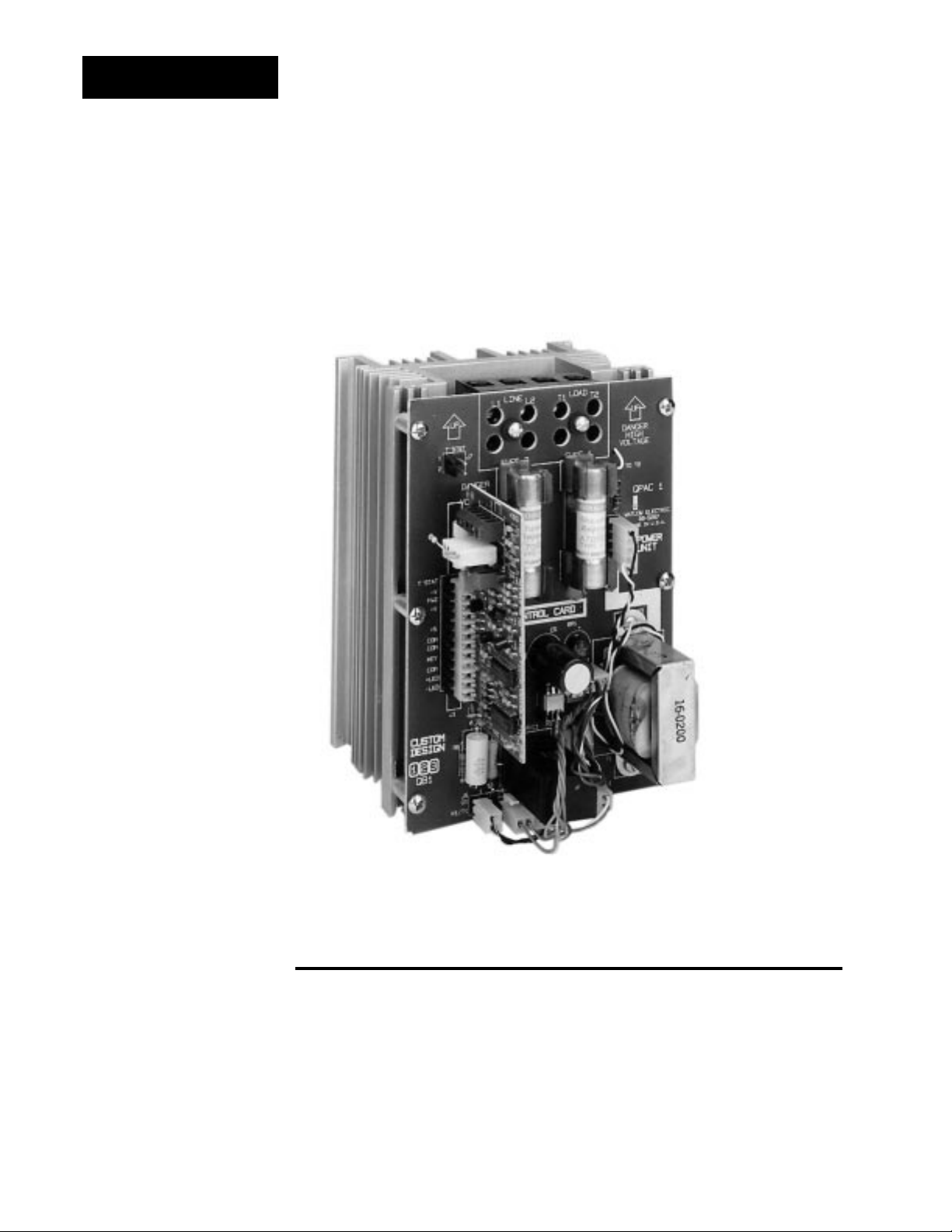
Figure 1 The QPAC-01
SCR Power Control
Chapter 1
Starting Out With The QPAC,
Modular SCR Power Control
4
QPAC User's Manual
General Description
The QPAC Power Controls are a family of solid state controls used for electric
heating applications. A solid state power control provides output power that is
proportional to the input command signal from a temperature control. This
proportional output power helps to produce a closely controlled heater temperature, which saves energy and prolongs heater life by holding heater
elements at a nearly constant temperature.
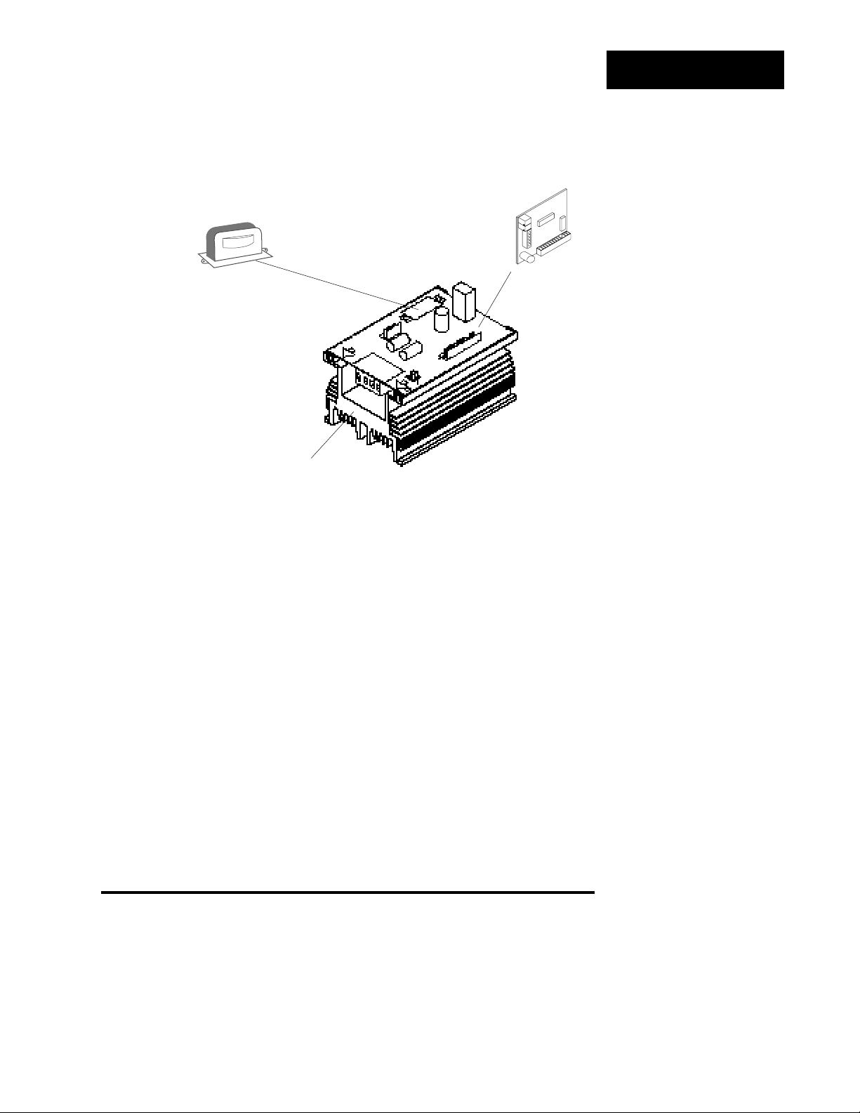
The QPAC has a modular construction with plug-in features for flexibility. The
three modules of the QPAC are the Power Base, Transformer, and Control
Getting Started, Chapter 1
Plug-in transformers (50/60 Hz.)
• 120Vac
• 208/240Vac
• 380Vac
• 415Vac
• 480Vac
• 575Vac, consult factory
Power Bases With Motherboards
• QPAC-01: 1Ø, 30 - 300A
• QPAC-32: 3Ø, 2 leg, 30 - 300A
• QPAC-33: 3Ø, 3 wire, 30 - 300A
Control Cards
• Solid state contactor, AC input, CA
• Solid state contactor, DC input, CD
• Burst firing (zero cross) fixed time base, BF
• Burst firing (zero cross) variable time base, BV
• Phase angle control, AF *
• Phase angle control with current limiting, AL *
* Note: For 1Ø and 3Ø, 3 wire controls
only; not for 3Ø, 2 leg controls.
QBF 08-5289
U2
1
U
TB1
Starting Out
Starting Out
Figure 2 QPAC Modularity
Overview
Card. See Figure 2. Power Bases are avaliable in 30 to 300A ratings with
UL508 and C-UL listing and 400-1,000 amps non-agency approved in single
phase, three phase-two leg and three phase-three wire configurations. A
Transformer plugged into the Power Base allows the QPAC to operate on any
voltage from 120 to 480Vac fan. 575Vac consult factory. The plug-in Control
Card sets the QPAC’s firing mode. Control Cards are available in solid state
contactor, burst firing (zero cross), or phase angle firing with a wide variety of
options. This modular approach, using a standard Power Base with plug-in
Transformers and Control Cards, allows power control users, distributors and
OEMs to maintain minimum inventories while still providing rapid service.
The different QPACs provide the types of power control needed for different
power sources and loads. The QPAC-01 is designed for all single phase
power sources and loads. The QPAC-32 is for three phase zero cross applications such as resistance heating elements, balanced or unbalanced. The
QPAC-33 is best suited for balanced three phase, phase angle applications
requiring soft start or current limiting, or with inductive loads.
Steps To Put Your Power Control To Work
To put your QPAC to work, we suggest the following steps:
• Read the User's Manual.
• Plan your installation and wiring.
• Mount the QPAC.
• Wire your QPAC to the system.
• Start the system and, if applicable, adjust the bias and gain on the QPAC.
• That's all there is to it!
QPAC User's ManualGetting Started, Chapter 1
5

Mounting
Starting Out
Installation
Chapter 2
How to Install and Wire the QPAC
System Planning
This chapter tells you how to install the QPAC. All mounting and wiring information is right here. Watlow power controls are thoroughly tested before
leaving the factory, so the QPAC is ready to install when you receive it.
This chapter is divided into three sections which describe the three steps you
need to do to install the QPAC—mounting, power wiring and control card
wiring. The first section lists the mounting information for each of the three
types of QPACs, which, depending on amperage, use one of five case styles.
The second section describes the power and load wiring of the QPACs and
semiconductor fuses, if required. The last section describes the input signal
wiring to the QPAC Control Card.
Before you begin working, read through this chapter to gain an understanding
of the entire installation. Consider the installation carefully. Plan the power,
load, and input signal wiring before mounting the QPAC. Also refer to any
noise guidelines in the temperature control documentation before proceeding.
∑
WARNING:
To avoid potential
electric shock and
other hazards, all
mounting and wiring
for the QPAC must
conform to the National Electric Code
(NEC) and other locally applicable
codes.
Table 1 QPAC Wiring Data
Mounting the QPAC ∫
The physical size and mounting dimensions of the QPACs are different for
different current ratings. Find the "Case Style" photo on the next pages which
match your QPAC. The table and figure accompanying each case style will
give you corresponding physical dimensions and mounting footprint. The table
also indicates if the units are equipped with fans and externally-mounted fuses.
External fuse mounting templates also accompany the case style drawings. All
QPACs must be mounted vertically, power connections on top, for proper
cooling. Use the wiring data table below for wire sizes and bending radii.
Current Semi- Minimum Bending Radius Lugs QPAC Fuse
(Amps) conduc- Recom- Accept Model Mounting
tor Fuse mended inches (mm) # Wire Number
Rating Wire Size
(Amps)
30 2ea, 20 10 N/A 18 to 4 Q01 Onboard
2ea, 40 Q32 External
3ea, 40 Q33 External
50 2ea, 30 8 1.5 (38) 18 to 4 Q01 Onboard
2ea, 70 Q32 External
3ea, 70 Q33 External
75 100 4 2 (51) 8 to 0 All External
100 125 1 3 (76) 8 to 0 All External
150 200 3/0 4 (102) 4 to 3/0 All Onboard
200 250 250 MCM 4.5 (114) 6 to 350 MCM All Onboard
300 400 500 MCM 8 (203) 4 to 500 MCM All Onboard
QPAC User's Manual
6
Install and Wire, Chapter 2
Case Style A
Starting Out
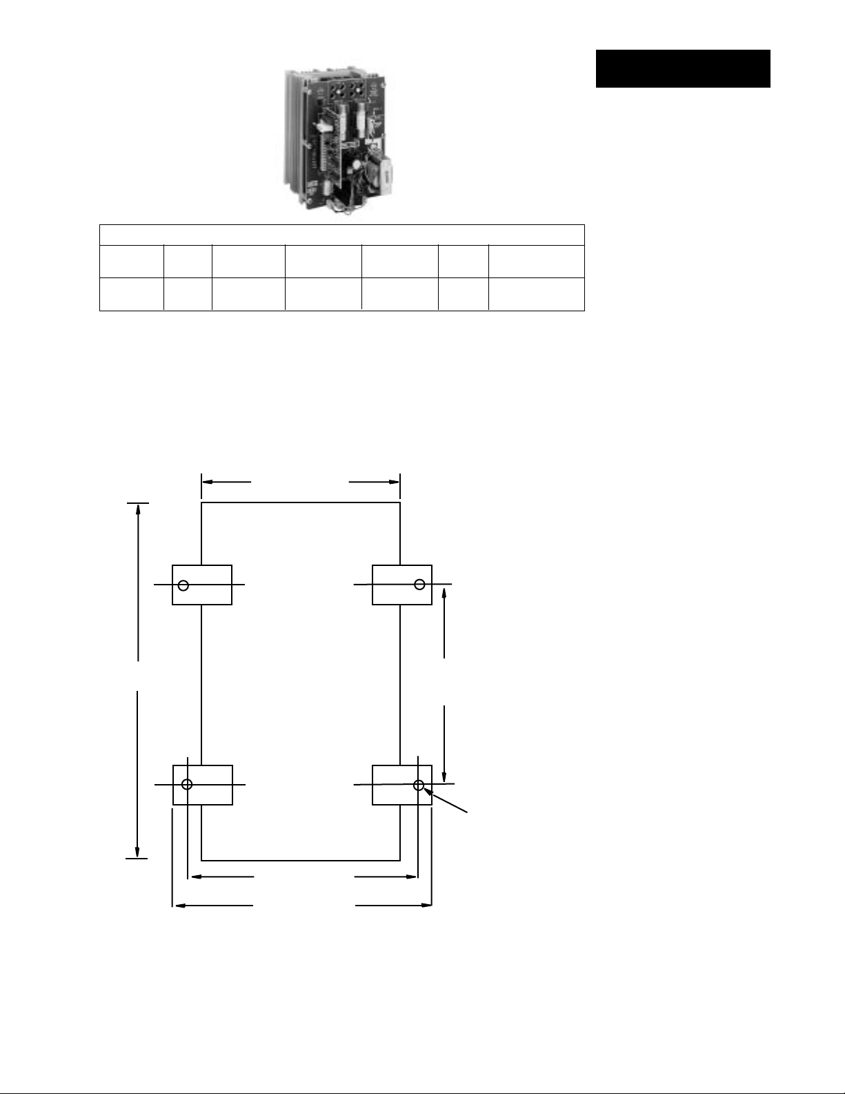
Figure 3 QPAC Case Style A
Case Style A Dimensions
Model Amps Height (H) Width Depth Fans Fuses
in (mm) in (mm) in (mm)
QPAC-01 30 7 178 See 6.5 165 None Two, Onboard
QPAC-01 50 9 229 Below 6.5 165 None Two, Onboard
ç
5.00 (127mm)
H
H less
2.00 (50.8mm)
Table 2 QPAC Case Style A
Overall Dimensions
Figure 4 QPAC Case Style A
Mounting Footprint
ç
CAUTION:
Mount the QPAC
vertically (height
dimension vertical)
for proper cooling.
Failure to do so
could result in
power control
malfunction.
5.80 (147mm)
6.60 (168mm)
Mounting Clip
Hole 0.19 (5mm)
QPAC User's ManualInstall and Wire, Chapter 2
7
Case Style B
Starting Out
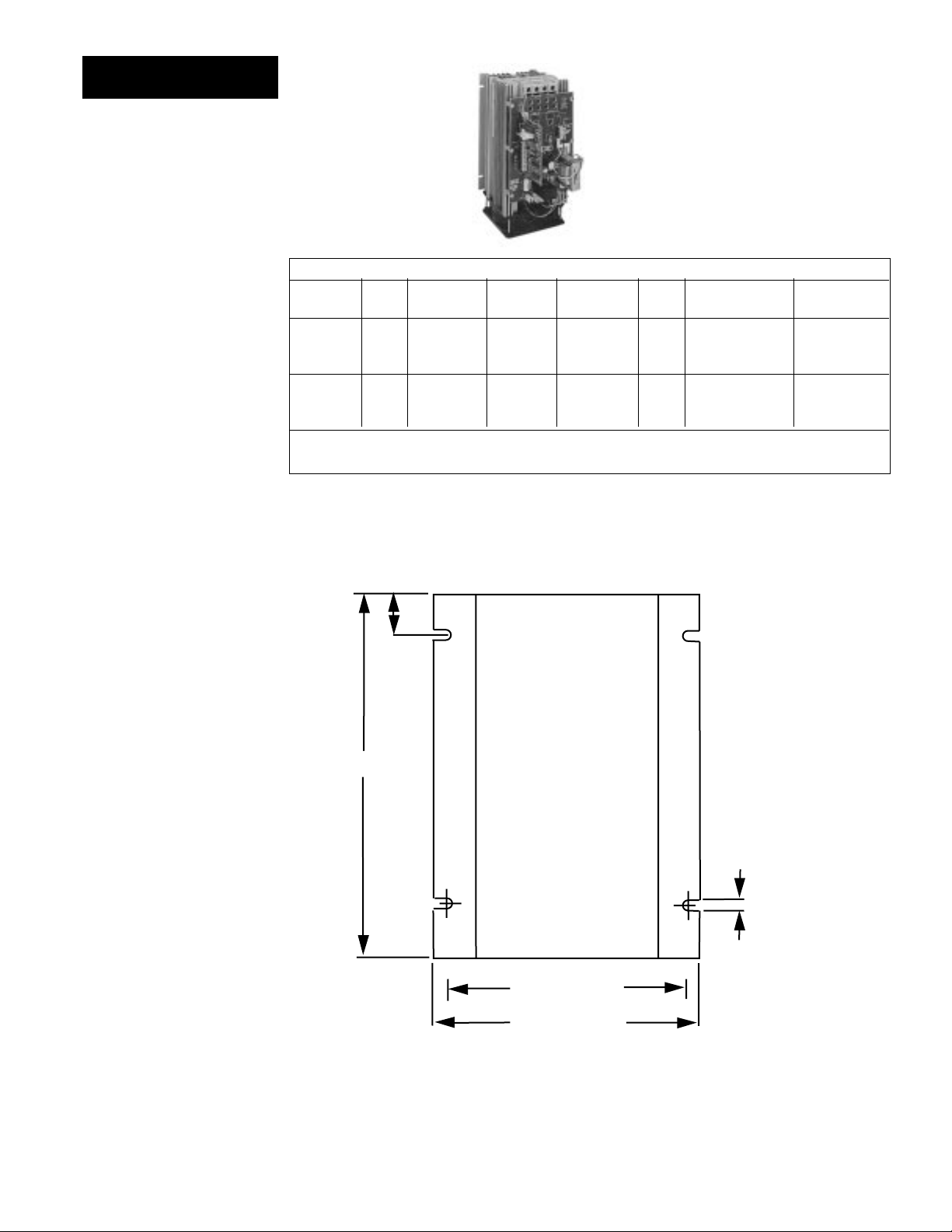
Figure 5 QPAC Case Style B
Table 3 QPAC Case Style B
Overall Dimensions
Figure 6 QPAC Case Style B
Mounting Footprint
ç
CAUTION:
Mount the QPAC
vertically (height
dimension vertical)
for proper cooling.
Failure to do so
could result in
power control
malfunction.
Case Style B Dimensions
Model Amps Height (H) Width Depth Fans Fuses Holder (max.)
in (mm) in (mm) in (mm) in (mm)
QPAC-32 30 10.5 267 5 127 8.5 208 One Two, External* 5.69 145
QPAC-01 75 10.5 267 5 127 8.5 208 One One, External** 4.90 124
QPAC-01 100 10.5 267 5 127 8.5 208 One One, External** 4.90 124
QPAC-32 50 10.5 267 5 127 8.5 165 One Two, External* 5.69 145
QPAC-32 75 14.5 368 5 127 8.5 229 One Two, External** 4.90 124
QPAC-32 100 14.5 368 5 127 8.5 208 One Two, External** 4.90 124
* Note: See external fuse mounting drawing, Figure 7, Page 9.
**Note: See external fuse mounting drawing, Figure 8, Page 10.
ç
1.00
(25mm)
H
QPAC User's Manual
8
0.19
(5mm)
4.50 (114mm)
5.07 (129mm)
Install and Wire, Chapter 2
Use the next two pages as templates for mounting your fuse holder kit. Choose
the size that matches your kit and carefully punch out the template along the
perforation.
5.69
(145mm)
5.07
(129mm)
3.63
(92mm)
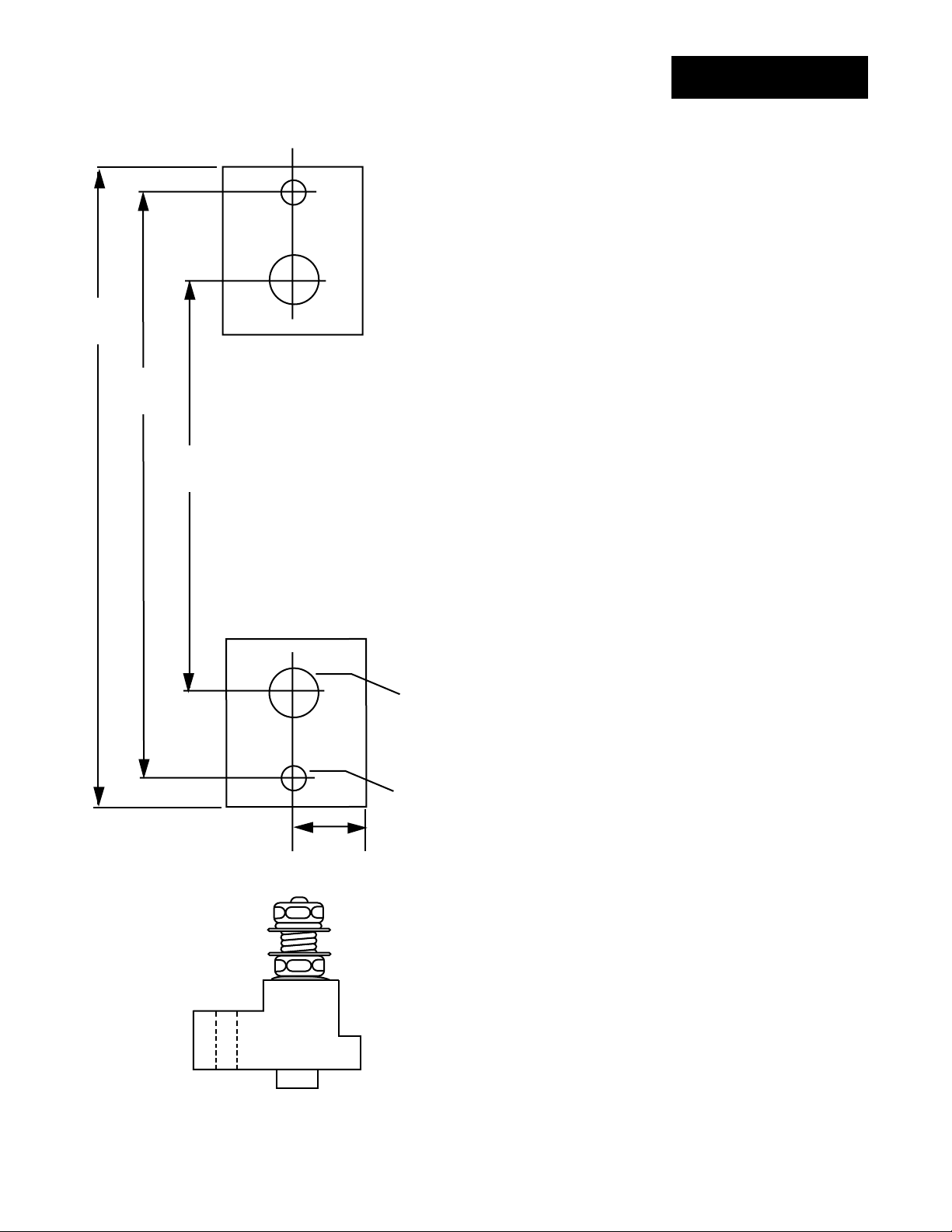
Fuse Template
Starting Out
ç
CAUTION:
Spacing for multiple
fuses must conform
to the National
Electric Code (NEC)
and any other local
electrical codes.
B
A
B
(16mm)
A
0.63
0.44
(11mm
0.22
(6mm)
Drill & tap
hole "B"
for #10
fasteners
Stud Size 5/16"
Fuse Holder
(side view)
Figure 7 Fuse Holder Kit
Mounting Template
for:
QPAC-32, 30 & 50A
(2 Fuse Kits)
QPAC-33, 30 & 50A
(3 Fuse Kits)
QPAC User's ManualInstall and Wire, Chapter 2
9
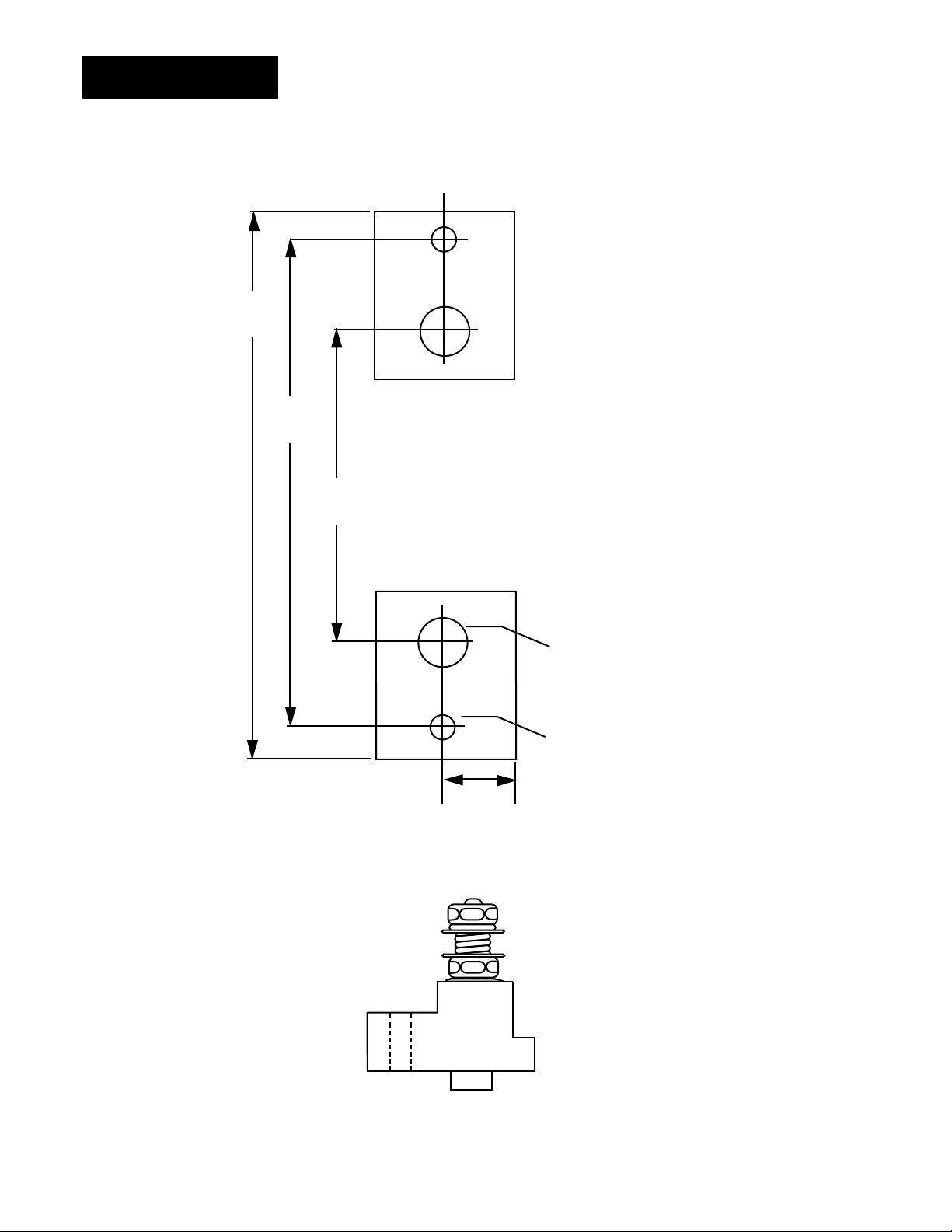
Fuse Template
Starting Out
4.90
(124mm)
ç
CAUTION:
Spacing for multiple
fuses must conform
to the National
Electric Code (NEC)
and any other local
electrical codes.
Use this page as a template for mounting your fuse holder kit. Choose the size
that matches your kit and carefully punch out the template along the perforation.
4.28
(109mm)
2.84
(72mm)
Figure 8 Fuse Holder Kit
Mounting Template
for:
QPAC-01, 75 & 100A
(1 Fuse Kit)
QPAC-32, 75 & 100A
(2 Fuse Kits)
QPAC-33, 75 & 100A
(3 Fuse Kits)
A
B
0.63
(16mm)
0.44
(11mm
0.22
(6mm)
Drill & tap
hole "B"
for #10
fasteners
Stud Size 5/16"
Fuse Holder
(side view)
QPAC User's Manual
10
B
A
Install and Wire, Chapter 2
Case Style C
Starting Out
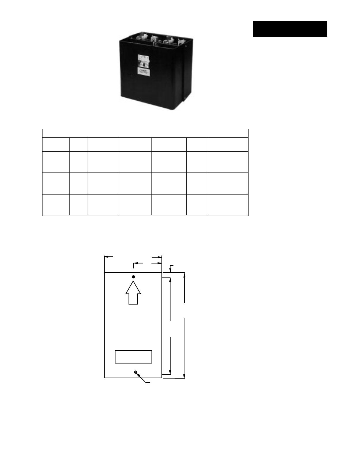
Figure 9 QPAC Case Style C
Case Style C Dimensions
Model Amps Height Width Depth Fans Fuses
in (mm) in (mm) in (mm)
QPAC-01 150 13 330 6.9 175 10.25 260 One On Heat Sink
QPAC-01 200 13 330 6.9 175 10.25 260 One On Heat Sink
QPAC-01 300 13 330 6.9 175 10.25 260 One On Heat Sink
QPAC-32 150 13 330 14.0 348 10.25 260 Two On Heat Sink
QPAC-32 200 13 330 14.0 348 10.25 260 Two On Heat Sink
QPAC-32 300 13 330 14.0 348 10.25 260 Two On Heat Sink
QPAC-33 150 13 330 21.0 533 10.25 260 Three On Heat Sink
QPAC-33 200 13 330 21.0 533 10.25 260 Three On Heat Sink
QPAC-33 300 13 330 21.0 533 10.25 260 Three On Heat Sink
Note: On 575 V~(ac) applications, the fuses are mounted external to the QPAC.
ç∫
7.00 (178mm)
3.50 (89mm)
U
P
MOUNT
3.63
(92mm)
13.00
(330mm)
11.75
(299mm)
Table 4 QPAC Case Style C
Overall Dimensions
ç
CAUTION:
Mount the QPAC
vertically (height
dimension vertical)
for proper cooling.
Failure to do so
could result in
power control
malfunction.
∫
WARNING:
Style C heatsinks
are electrically HOT.
FAN
0.38 (10mm)
2 PL
Figure 10 QPAC Case Style C,
QPAC-01, 150, 200,
300A Single Phase
Mounting Footprint
QPAC User's ManualInstall and Wire, Chapter 2
11
 Loading...