

Page 1

PPC-2000
User’s Guide
WATLOW
1241 Bundy Boulevard
Winona, Minnesota USA 55987
Phone: +1 (507) 454-5300,
Fax: +1 (507) 452-4507
Part No. 0600-3000-2000 Rev 2.3d
http://www.watlow.com
Page 2

Page 3

PPC-2000 Adaptive Control
Addendum
Scope
This document describes the additional features and functionality found
in the PPC-2010-xxB with adaptive control. Refer to the PPC-2000
User’s Guide regarding all other functionality which is the same as the
standard version.
Introduction
The Watlow Anafaze PPC-2000 controller offers these standard options:
• Forty-eight loops of conventional PID control with auto-tuning
capability
-or-
• Eight loops of adaptive control plus 24 loops of conventional PID
control with auto-tuning for a total of 32 loops (the option described
in this document)
ANAWIN3 HMI software is available to support either option. A mix of
these options is not supported by ANAWIN3.
ANAWIN3 Software Installation
Follow the standard instructions to install and setup ANAWIN3. In the
setup program select the Adaptive Control option.
Spreadsheet Overview Screen
Several new parameters and options appear on the Spreadsheet Overview
screen in support of the adaptive control option. These parameters and
options are applicable only for the first eight channels and are omitted or
ignored for channels 9 to 32.
Control Type
An additional option appears for Control Type. Select Adaptive to enable
adaptive control and tuning on a channel. This option is only valid for
channels 1 to 8.
Values: PID1 (0), PID2 (1), Adaptive (2) and Retransmit (3)
Default: PID1 (0)
Modbus Address (Channels 1 to 32): 46401 to 46432
Parameter Number: 19
LogicPro Driver: Database
LogicPro Address (Channels 1 to 32): 19.1 to 19.32
Adaptive Addendum PPC-2000 User's Guide
0600-0049-0001 rev C Watlow Anafaze 1
Page 4

Adaptive Mode
When Control Type is set to Adaptive, this parameter can be used to
pause tuning or to reset the adaptive algorithm and have it relearn the
system. This parameter has no effect on control if the Control Type for
the loop is set to an option other than Adaptive.
Values: Adapt (0), Reset (1) and Hold (2)
Default: Reset (1)
Modbus Address (Channels 1 to 32): 49001 to 49032
Parameter Number: 21
LogicPro Driver: Database
LogicPro Address (Channels 1 to 32): 21.1 to 21.32
Table 1. Adaptive Mode Settings
Setting Description
Adapt The normal setting for a loop with Control Type set to
Adaptive. The loop is adapting and tuning while controlling.
Reset Select this option to have the control loop start from scratch
and relearn the load characteristics. The Control Mode must
be set to Off or Manual to select this option for an adaptive
loop. This is the normal setting for a loop with Control Type
set to a value other than Adaptive.
Hold Select this option to have the control loop stop learning
temporarily but retain the learned load characteristics. For
example in the event that maintenance will be performed, it
may be advantageous to pause adapting to avoid false data
being introduced. Select this option anytime you want the
controller to stop adapting and continue to control with the
parameters learned up to that point.
Plant Delay
This parameter indicates the amount of delay in seconds in the load. This
characteristic of the load or plant has a significant impact on adaptive
control. A larger number indicates a longer delay between, for example
an increase in heater power and an increase in the temperature.
Choose Automatic and then set the Control Mode to Auto to have the
adaptive algorithm determine the plant delay for the loop. The loop must
be at least 40 degrees below set point and the controller must observe a
temperature change of at least 20 degrees to determine the Plant Delay.
If you have determined the Plant Delay with the PPC-2000's adaptive
control previously and found the performance acceptable, you may
choose the delay directly and the loop will use the value you choose
rather than measure it.
This setting is not reset by the Adaptive Mode parameter's Reset option.
To have the controller relearn the Plant Delay, set the loop's Control
Mode to Manual or Off, set the Plant Delay to Automatic, and then set
the Control Mode to Auto again.
Adaptive Addendum PPC-2000 User's Guide
0600-0049-0001 rev C Watlow Anafaze 2
Page 5
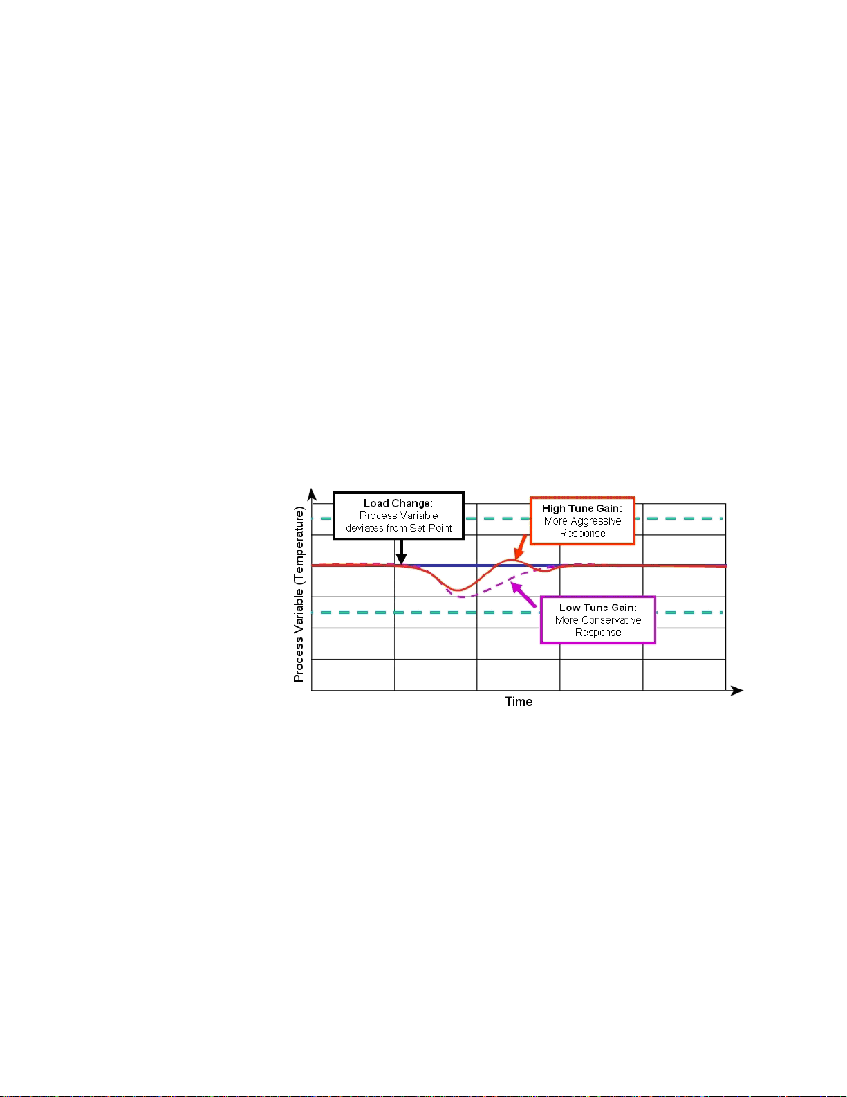
Tuning Gain
This parameter has no effect on control if the Control Type for the loop is
set to an option other than Adaptive.
Values: Automatic (0) and 1 (1) to 600 seconds (600)
Default: Automatic (0)
Modbus Address (Channels 1 to 32): 49051 to 49082
Parameter Number: 28
LogicPro Driver: Database
LogicPro Address (Channels 1 to 32): 28.1 to 28.32
This parameter indicates the amount of delay in seconds in the load. This
characteristic of the load or plant has a significant impact on adaptive
control. A larger number indicates a longer delay between, for example
an increase in heater power and an increase in the temperature.
Values: Aggressive (0), Nominal (1), Damped 1 (2), Damped 2 (3),
Damped 3 (4) and Damped 4 (5)
Default: Nominal (1)
Modbus Address (Channels 1 to 32): 46551 to 46682
Parameter Number: 29
LogicPro Driver: Database
LogicPro Address (Channels 1 to 32): 29.1 to 29.32
Figure 1. The Effect of Tuning Gain on Recovery from a
Load Change
Using Adaptive Control
To set up adaptive control on one or more channels:
1. Open the
2. On the
a. Choose the appropriate
b. Choose
c. For any linear voltage, current, or pulse sensors, set the linear
3. On the
Adaptive Addendum PPC-2000 User's Guide
0600-0049-0001 rev C Watlow Anafaze 3
Spreadsheet Overview screen in ANAWIN3.
Inputs spreadsheet for each analog input you have wired:
Input Type for the sensor.
Units.
scaling parameters (
and
PV Hi). See Setting up User Selectable Linear Inputs on
page 98 of the PPC-2000 User's Guide.
Channels spreadsheet for each channel:
Input Signal Lo, Input Signal Hi, PV Lo,
Page 6

a. In the PV Source field, choose the input that you want to
monitor or use as feedback for closed-loop control.
b. In the
Heat Output Dest and/or Cool Output Dest fields,
choose the outputs that you want to use for closed-loop control.
c. Choose a
d. Set the
Output Type
4. On the
a. Set the
Output.
5. On the
Heat/Cool Output Type for each output.
Heat/Cool Cycle Time for any outputs with Heat/ Cool
set to Time Prop.
Digital I/O spreadsheet:
Direction for each I/O point to be used for control to
Channels spreadsheet:
a. For channels other than the adaptive ones, if both heat and cool
outputs are used, set the
Spread.
b. For each channel that will perform adaptive control, for the
Control Type, choose Adaptive.
c. Set the
Set Point to the desired value at least 40 engineering
units (typically degrees) above the process variable.
d. Set the
Control Mode to Auto to begin adaptive closed-loop
control.
NOTE: Only channels 1 to 8 can be selected for adaptive control.
Adaptive Addendum PPC-2000 User's Guide
0600-0049-0001 rev C Watlow Anafaze 4
Page 7

PPC-2000 User's Guide
Addendum
Overview
This document contains additional specifications for the PPC-2000 system.
Environmental Specifications
Table 1 here contains specifications in addition to those found in tables 7.4, 7.15, 7.23,
7.31, 7.39, 7.46, 7.52, 7.57, 7.62, 7.67 in the PPC-2000 User's Guide.
TABLE 1. Environmental Specifications
Altitude 2000 meters max
Non-Condensing Humidity 10 to 95%
Relative Humidity 80% max (ambient temperature <= 31° C)
50% max (ambient temperature = 40° C)
Pollution Category Degree 2 (per IEC 664)
Operating Temperature Range 0 to 60° C (32 to140° F)
Storage Temperature Range -20 to 70° C (-4 to 158° F)
PPC IPS International Power Supply Specifications
Table 2 here contains specifications in addition to those found in table 7.75 in the PPC2000 User's Guide.
TABLE 2. Power Specifications
Input (Mains Supply) 88 to 132 Vac (120 Vac nominal)
176 to 264 Vac (240 Vac nominal)
Voltage Fluctuation < +10% of nominal voltage
Transient Over-Voltage Category II per IEC 664
Output V1: +5 Vdc @ 6 A
V2: +24 Vdc @ 4 A
Input Frequency 47 to 440 Hz
Peak Current Output 9A @ 5Vdc
6A @ 24 Vdc
1241 Bundy Blvd.
Winona, MN 55987
Phone: (507) 494-5656
Fax: (507) 452-4507
©2004 Watlow Page 1 of 1
Page 8

Copyright © 1998-2002
Watlow Anafaze
Information in this manual is subject to change without notice. No part of this publication may be
reproduced, stored in a retrieval system, or transmitted in any form without written permission
from Watlow Anafaze.
Warranty
Watlow Anafaze, Incorporated warrants that the products furnished under this Agreement will be
free from defects in material and workmanship for a period of three years from the date of shipment. The Customer shall provide notice of any defect to Watlow Anafaze, Incorporated within one
week after the Customer's discovery of such defect. The sole obligation and liability of Watlow
Anafaze, Incorporated under this warranty shall be to repair or replace, at its option and without
cost to the Customer, the defective product or part.
Upon request by Watlow Anafaze, Incorporated, the product or part claimed to be defective shall
immediately be returned at the Customer's expense to Watlow Anafaze, Incorporated. Replaced or
repaired products or parts will be shipped to the Customer at the expense of Watlow Anafaze,
Incorporated.
There shall be no warranty or liability for any products or parts that have been subject to misuse,
accident, negligence, failure of electric power or modification by the Customer without the written
approval of Watlow Anafaze, Incorporated. Final determination of warranty eligibility shall be
made by Watlow Anafaze, Incorporated. If a warranty claim is considered invalid for any reason,
the Customer will be charged for services performed and expenses incurred by Watlow Anafaze,
Incorporated in handling and shipping the returned unit.
If replacement parts are supplied or repairs made during the original warranty period, the warranty
period for the replacement or repaired part shall terminate with the termination of the warranty
period of the original product or part.
The foregoing warranty constitutes the sole liability of Watlow Anafaze, Incorporated and the Customer's sole remedy with respect to the products. It is in lieu of all other warranties, liabilities, and
remedies. Except as thus provided, Watlow Anafaze, Inc. disclaims all warranties, express or
implied, including any warranty of merchantability or fitness for a particular purpose.
Please Note
: External safety devices must be used with this equipment.
Page 9

Table of Contents iii
List of Figures ix
List of Tables xv
Overview 1
Manual Contents 1
Getting Started 2
Safety symbols 2
Contacting Watlow Anafaze 2
Initial Inspection 2
Product Features 3
System Components 3
PPC-2000 Modules 6
PPC-2000 Terminal Boards 8
Additional Components 9
Safety 9
External Safety Devices 10
External Switch Disconnect 11
Battery Safety 11
Product Markings and Symbols 11
Table of Contents
Hardware Installation 13
Power Supply Requirements 13
Mounting the Power Supply 15
Hardware Configuration 17
Module Addresses 17
PPC-2010 Jumper Settings 18
PPC-2030 Dip Switch Settings 19
PPC-2030 Jumper Settings 20
PPC-2040 Jumper Settings 21
PPC-205x Jumper Settings 22
Module Disassembly 26
Mounting Modules 26
DIN Rail Mounting 27
Doc.# 30002-00 Rev 2.3 Watlow Anafaze iii
Page 10

Table of Contents PPC-2000 User’s Guide
Mounting Terminal Boards 28
DIN Rail Mounting 31
DIN Rail Removal 32
Panel Mounting 33
System Wiring 34
Wiring Recommendations 35
Noise Suppression 35
Avoiding Ground Loops 37
Connecting I/O to the PPC-2010 37
Connecting the TB50 to the PPC-2010 Module 37
TB50 Connections 38
Connecting Digital Inputs 40
Connecting Counter or Frequency Inputs 41
Connecting Digital Outputs 41
SDAC Connections 43
Connecting Analog Inputs to the PPC-2021 — 2025 45
Connecting the AITB to the PPC-202x 45
Sensor Keys 46
AITB Connections 47
Connecting Thermocouples 49
Connecting RTDs 50
Connecting Sensors with Linear Voltage Signals 52
Connecting Sensors with Linear Current Signals 53
Connecting the Encoder Input Cable to the PPC-2030 55
Encoder Wiring 57
Encoder Connections without the EITB 59
Analog Output Connections 60
Connecting I/O to the PPC-2040 61
Connecting the TB50 to the PPC-2040 Module 61
TB50 Connections 62
Connecting Digital Inputs 64
Connecting Counter or Frequency Inputs 64
Connecting Digital Outputs 65
Connecting to the Relay Outputs on the PPC-206x 70
Wiring PPC-2062 Relay Outputs 71
Using Snubbers for Relay Outputs 73
Connecting Power 77
PPC-IPS-2 Power Supply 77
Processor Module 77
Connecting Communication Ports 78
Communication Ports 78
Connecting RS-485 Communications 81
iv Watlow Anafaze Doc.# 30002-00 Rev 2.3
Page 11

PPC-2000 User’s Guide Table of Contents
Operating with AnaWin3 89
Type Definitions 89
Closed-Loop Control 89
Feedback 90
Control Algorithm 90
Control Output Signal Forms 90
Heat and Cool Outputs 90
Prerequisites 93
Background 93
Using AnaWin3 to Tune 94
Alarms 95
Failed Sensor Alarms 95
Global Alarm 95
Process Alarms 95
Alarm Delay 96
Setting up Process and Deviation Alarms 97
Setting Input Signal Lo and Input Signal Hi 99
Setting Engineering Units 99
Setting PV Lo and PV Hi 99
Setting Decimal Places 100
Linear 4-20mA Input Example 101
Process Variable Retransmit 102
Setting up Process Variable Retransmit 103
Process Variable Retransmit Example 104
Cascade Control 105
Setting up Cascade Control 106
Cascade Control Example 106
Ratio Control 109
Setting up Ratio Control 110
Differential Control 112
Remote Set Point 112
Logic Programs 112
Setting up Outputs for Use with a Logic Program 113
Using Logic to Set an Analog Input 113
Starting and Stopping Logic Programs 113
Controller Parameters 115
Channels 115
Digital I/O 132
Soft Integer 136
Soft Boolean 137
Doc.# 30002-00 Rev 2.3 Watlow Anafaze v
Page 12

Table of Contents PPC-2000 User’s Guide
Troubleshooting 141
General Description 141
PPC-2010 Processor 141
Processor Module LEDs 147
PPC-2040 Digital I/O 151
PPC-207x Digital In 153
Troubleshooting and Corrective Actions 154
Digital Inputs and Outputs 154
Process Variable 154
Communications 155
Resetting Closed-Loop Control Parameters 156
Disabling Control 157
LogicPro and Modbus Reference 159
Overview 159
Text Conventions in the Database Sections 159
The PPC-2000 Database 160
Data Table Organization 161
How LogicPro Accesses the Database 162
Analog and Counter Input Parameters in the Database 163
Accessing Analog and Counter Input Parameters with Modbus 163
Accessing Analog and Counter Input Parameters with LogicPro 163
Analog Input Numbers and Address Offsets 164
Analog and Encoder Input Parameters 168
Channel Parameters in the Database 172
Accessing Channel Parameters with Modbus 172
Accessing Channel Parameters with LogicPro 173
Channel Parameters for Heat and Cool Outputs 173
Channel Parameters 173
State and Logic 195
Accessing Digital I/O Parameters with Modbus 195
Digital I/O Numbers and Address Offsets 196
Digital I/O Parameters 200
Accessing Analog Outputs with Modbus 202
Accessing Analog Outputs with LogicPro 202
Analog Outputs and Modbus Addresses 202
Analog Output Value 204
Soft Bool and Soft Int Registers in the Database 205
Accessing Soft Bool and Soft Int Registers with Modbus 205
Accessing Soft Bool and Soft Int Registers with LogicPro 205
Soft Bool and Soft Int Registers 205
Global Parameters in the Database 206
Accessing Global Parameters with Modbus 206
Communications Parameters 207
Global Database Parameters 209
vi Watlow Anafaze Doc.# 30002-00 Rev 2.3
Page 13

PPC-2000 User’s Guide Table of Contents
Tuning and Control 219
Introduction 219
Control Algorithms 220
On/Off Control 220
Output Control Forms 224
Output Filter 225
Proportional Band (PB) Settings 226
Integral Settings 226
Derivative Settings 227
General PID Constants by Application 228
Proportional Band Only (P) 228
Proportional with Integral (PI) 228
PI with Derivative (PID) 228
Specifications 229
System Specifications 229
Safety and Agency Approvals 229
Physical Specifications 230
Power Specifications 230
PPC-2010 Processor Specifications 231
PPC-205x Analog Out Specifications 247
PPC-206x Digital Output Specifications 250
PPC-207x Digital In Specifications 253
PPC-EITB-1 Encoder Input Terminal Block Specifications 258
PPC-TB50-SCSI, 50-Pin Specifications 261
SDAC Specifications 265
Inputs 266
Analog Outputs 267
Appendix A: Modbus Protocol 269
Query 270
Response 270
Message Framing 271
Address Field 272
Function Field 272
Data Field 273
Error Checking Field 273
Field Format 273
Parity Checking 274
CRC Checking 275
Read Examples 280
Appendix B: Declaration of Conformity 283
Glossary 285
Doc.# 30002-00 Rev 2.3 Watlow Anafaze vii
Page 14

Table of Contents PPC-2000 User’s Guide
viii Watlow Anafaze Doc.# 30002-00 Rev 2.3
Page 15

Overview 1
Figure 1.1—System Diagram 4
Figure 1.2—Sample PPC-2000 System 6
Hardware Installation 13
Figure 2.1—PPC-IPS-2 DIN Mounting Dimensions 15
Figure 2.2—PPC-IPS-2 Panel Mounting Dimensions 16
Figure 2.3—Sample Addresses 17
Figure 2.4—PPC-2010 Jumpers 19
Figure 2.5—PPC-2030 Jumpers and Switches 20
Figure 2.6—PPC-2040 Jumper Settings 21
Figure 2.7—PPC-205x Jumpers 23
Figure 2.8—Assembled Modules Top View 24
Figure 2.9—Assembled Modules Bottom View 25
Figure 2.10—Modules Bottom/Side View 25
Figure 2.11—DIN Rail Latches 27
Figure 2.12—Mounting Assembled PPC Modules on a DIN rail (side) 27
Figure 2.13—AITB Dimensions / Clearances 29
Figure 2.14—EITB Dimensions / Clearances 30
Figure 2.15—TB50 Dimensions / Clearances 31
Figure 2.16—TB50 Mounted on DIN Rail (Front) 32
Figure 2.17—TB50 Mounted on DIN Rail (Side) 32
Figure 2.18—TB50 Panel Mounted 33
Figure 2.19—SDAC Dimensions 34
Figure 2.20—PPC-2010 Connection to TB50 38
Figure 2.21—Wiring Digital Inputs 41
Figure 2.22—Encoder with 5Vdc TTL Signal 41
Figure 2.23—Powering Output with 5Vdc from PPC Supply 42
Figure 2.24—Powering Output with 12-24Vdc from PPC supply 42
Figure 2.25—Powering Output with Separate Power Supplies 42
Figure 2.26—Recommended circuitry for CPUWatchdog 43
Figure 2.27—Wiring Single/Multiple SDACs 44
Figure 2.28—PPC-2021 — 2025 Connection to AITB 45
Figure 2.29—Inserting Sensor Keys in AITB 46
Figure 2.30—An Input Key 47
Figure 2.31—Thermocouples Connected to Differential Inputs 1 and 2 49
Figure 2.32—Thermocouples Connected to Single-ended Inputs 1 and 2 50
Figure 2.33—Wiring 2-Wire RTDs: Input 1 and 2 Shown 51
Figure 2.34—Wiring 3-Wire RTDs: Input 1 and 2 Shown 51
List of Figures
Doc.# 30002-00 Rev 2.3 Watlow Anafaze ix
Page 16

List of Figures PPC User’s Guide
Figure 2.35—Connecting Linear Voltage Signals to Differential Inputs 1 and 2 52
Figure 2.36—Connecting Linear Voltage Signals to Single-ended Inputs 1 and 2 53
Figure 2.37—Connecting Current Inputs to a Differential Input Module:
Input 1, 2, and 3 Shown 53
Figure 2.38—Connecting Current Inputs to a Single-ended Analog Input
Module: Input 1 and 2 Shown 54
Figure 2.39—PPC-2030 Connections (Bottom View) 55
Figure 2.40—PPC-EITB-1 56
Figure 2.41—EITB Single-ended Single Phase Connections: Input 1 and 2 Shown 57
Figure 2.42—EITB Single-ended Quadrature Connections: Input 1 and 2 Shown 58
Figure 2.43—EITB Differential Single Phase Connections: Input 1 and 2 Shown 58
Figure 2.44—EITB Differential Quadrature Connections: Input 1 and 2 Shown 59
Figure 2.45—PPC-2030 Analog Out Terminal Block 60
Figure 2.46—Analog Output Connections on a PPC-2030: Outputs 1 and 2 Shown 61
Figure 2.47—PPC-2040 Connection to TB50 62
Figure 2.48—Wiring Digital Inputs 64
Figure 2.49—Single Phase Connections: Input 1 and 2 Shown 64
Figure 2.50—Quadrature Connections: Inputs 1 and 2 Shown. 65
Figure 2.51—Powering Output with 5Vdc from PPC Supply 65
Figure 2.52—Powering Output with 12-24Vdc from PPC supply 66
Figure 2.53—Powering Output with Separate Power Supplies 66
Figure 2.54—PPC-205x Connections (Bottom View) 67
Figure 2.55—Analog Output Connections on a PPC-2050 Configured for Current:
Outputs 1 and 2 Shown 68
Figure 2.56—Analog Output Connections on a PPC-2050 Configured for Voltage:
Outputs 1 and 2 shown 69
Figure 2.57—Analog Output Connections on a PPC-2051 Configured for Current and
Voltage: Outputs 1 and 2 shown 69
Figure 2.58—PPC-206x Connections (bottom view) 70
Figure 2.59—Relay Output Connections on a PPC-2061:
Outputs 1, 2, 9 and 10 shown 71
Figure 2.60—Relay Output Connections on a PPC-2062: Outputs 1 and 2 Shown 72
Figure 2.61—Snubber Connections 73
Figure 2.62—PPC-207x Connections (bottom view) 74
Figure 2.63—Input Connections to a PPC-2070 or PPC-2072:
Inputs 1 and 2 shown 74
Figure 2.64—Input Connections to a PPC-2071 or PPC-2073:
Inputs 1,2, 9 and 10 Shown 75
Figure 2.65—Connecting a Current Sinking Field Device to a PPC-2072 or PPC-2073:
Input 1 Shown 75
Figure 2.66—Connecting a Current Sourcing Field Device to a PPC-2072 or
PPC-2073: Input 1 Shown 76
Figure 2.67—PPC-IPS-2 Power Connections 78
Figure 2.68—RS-232 and RS-485 RJ-Type Connectors 79
Figure 2.69—Connecting One PPC to a Computer Using RS-232 81
Figure 2.70—Connecting Multiple PPCs to a Computer Using RS-485 81
Figure 2.71—RS-485 Wiring 82
Figure 2.72—Two Wire RS-485 Wiring 84
Figure 2.73—Connecting Several PPCs with Short Cable Runs 84
x Watlow Anafaze Doc.# 30002-00 Rev 2.3
Page 17

PPC User’s Guide List of Figures
Operating with AnaWin3 89
Figure 3.1—Sample Screen Text 89
Figure 3.2—Process Variable Alarms 96
Figure 3.3—Linear Input Example 98
Figure 3.4—Linear Scaling of the Analog Input for Retransmit on the Heat or Cool
Output 102
Figure 3.5—Sample Application Using Process Variable Retransmit 104
Figure 3.6—How the Secondary Channel’s Set Point is Determined When the
Primary Channel Has Heat and Cool Outputs 105
Figure 3.7—How the Secondary Channel’s Set Point is Determined When the Primary
Channel Has Only a Heat Output 106
Figure 3.8—Sample Application Using Cascade Control 107
Figure 3.9—The Secondary Channel’s Set Point is Determined by the Primary
Channel’s Process Variable 109
Figure 3.10—Relationship between the Master Channel’s Process Variable and the
Ratio Channel’s Set Point. 110
Figure 3.11—Sample Application Using Ratio Control 111
Figure 3.12—Channels Spreadsheet 115
Figure 3.13—Output Scaling (Heat/Cool) Curves 121
Figure 3.14—Alarms Spreadsheet 123
Figure 3.15—Inputs Spreadsheet 127
Figure 3.16—Analog Input Names 127
Figure 3.17—Pulse Input Names 128
Figure 3.18—Soft Input Names 128
Figure 3.19—Channel Output Names 129
Figure 3.20—Dig I/O Spreadsheet 132
Figure 3.21—PPC-2010 and PPC-204X Digital I/O Names 133
Figure 3.22—PPC-206X and PPC-207X Digital I/O Names 133
Figure 3.23—Outputs Spreadsheet 135
Figure 3.24—Analog Output Names 135
Figure 3.25—Soft Int Spreadsheet 136
Figure 3.26—Soft BOOL Spreadsheet 137
Figure 3.27—PPC Globals Screen 138
Troubleshooting 141
Figure 4.1—Assembled Modules Top View 143
Figure 4.2—Assembled Modules Bottom View 143
Figure 4.3—PPC-2010 Internal View 144
Figure 4.4—PPC Assembled Modules Top View 145
Figure 4.5—PPC Assembled Modules Bottom View 146
Doc.# 30002-00 Rev 2.3 Watlow Anafaze xi
Page 18

List of Figures PPC User’s Guide
LogicPro and Modbus Reference 159
Figure 5.1—Sample Text 160
Figure 5.2—Output Scaling Curves 185
Tuning and Control 219
Figure 6.1—On/Off Control 220
Figure 6.2—Proportional Control 221
Figure 6.3—Proportional and Integral Control 222
Figure 6.4—Proportional, Integral and Derivative Control 223
Figure 6.5—Example Time Proportioning and Distributed Zero Crossing
Waveforms 224
Specifications 229
Figure 7.1—System Footprint 230
Figure 7.2—PPC-2010 Front View 231
Figure 7.3—PPC-2010 Bottom View 232
Figure 7.4—PPC-2021 Front View 236
Figure 7.5—PPC-2021 - 2025 Bottom View 236
Figure 7.6—PPC-2030 Front View 240
Figure 7.7—PPC-2030 Bottom View 241
Figure 7.8—PPC-2040 Front View 244
Figure 7.9—PPC-2050 Front View 247
Figure 7.10—PPC-2050 Bottom View 248
Figure 7.11—PPC-206x Front View 250
Figure 7.12—PPC-206x Bottom View 251
Figure 7.13—PPC-2070, PPC-2071 Front Views 253
Figure 7.14—PPC-207x Bottom Views 254
Figure 7.15—PPC-AITB-1 256
Figure 7.16—PPC-AITB Dimensions with Straight SCSI Cable 257
Figure 7.17—PPC-EITB-1 258
Figure 7.18—PPC-EITB Dimensions with HD-Type Cable 260
Figure 7.19—PPC-TB50-SCSI Dimensions 261
Figure 7.20—PPC-TB50-SCSI Dimensions with Straight SCSI Cable 262
Figure 7.21—PPC-TB50-SCSI Dimensions with Right-Angle SCSI Cable 263
Figure 7.22—PPC-IPS-2 264
Figure 7.23—SDAC Dimensions 266
Appendix A: Modbus Protocol 269
Figure A.1—Query—Response Cycle 270
xii Watlow Anafaze Doc.# 30002-00 Rev 2.3
Page 19

Overview 1
Table 1.1—PPC-2000 System Modules 5
Table 1.2—PPC-2000 Terminal Boards and Peripheral Modules 5
Table 1.3— Analog Terminal Board Keys 5
List of Tables
Hardware Installation 13
Table 2.2—Power Supply Current Requirements at 24Vdc 14
Table 2.3—Power Supply Screw Mounting 16
Table 2.4—System Modules and Addressing 18
Table 2.5—PPC-2010 Processor Module Jumpers 18
Table 2.6—PPC-2030 Analog Output Jumpers 21
Table 2.7—PPC-2040 Counter Input Jumpers 21
Table 2.8—PPC-205x Analog Out Jumpers 22
Table 2.9—Cable Recommendations 35
Table 2.10—Processor Module I/O Connections 39
Table 2.11—Sensor Keys 46
Table 2.12—Numbers and Types of Inputs by Module Type 47
Table 2.13—Sensor Connections to the AITB 48
Table 2.14—Power Connections on AITB 49
Table 2.15—Encoder Connections to the EITB Connected to J3 on the PPC-2030 56
Table 2.16—Encoder Connections to the EITB Connected to J4 on the PPC-2030 56
Table 2.17—Power Connections on EITB 57
Table 2.18—HD-15 Encoder Signal Connections 59
Table 2.19—HD-15 Power Connections 60
Table 2.20—Analog Output Connections on Encoder In Analog Out Module 60
Table 2.21—Digital I/O Module Connections 63
Table 2.22—Analog Output Connections on Analog Out Module 67
Table 2.23—Relay Output Connections on PPC-206x Digital Output Modules 72
Table 2.24—Digital Input Connections on PPC-207x Modules 76
Table 2.25—PPC-IPS-2 Voltage Input Switch Settings 77
Table 2.26—Power Supply Connections 77
Table 2.27—RS-232 Connector Pin Outs 79
Table 2.28—RS-485 Connector Pin Out and Connections 80
Table 2.29—RTS/CTS Pins in DB-9 and DB-25 Connectors 80
Table 2.30—485 Terminal Block Pin Assignment 83
Table 2.31—PPC-2010 Rotary Switch Configuration 86
Doc.# 30002-00 Rev 2.3 Watlow Anafaze xiii
Page 20

List of Tables PPC User’s Guide
Operating with AnaWin3 89
Table 3.1—Control Types PID1 and PID2 91
Table 3.2—Alarm Types 95
Table 3.3—Range and Sensitivity of theCustom Linear Input Types 99
Table 3.4—PV Range permitted for various Decimal Places Settings 100
Table 3.5—Scaling Parameters for 0-10Vdc Linear Input Example 101
Table 3.6—Scaling Parameters for 4-20mA Linear Input Example 101
Table 3.7—Scaling Parameters for 0-1Vdc Linear Input Example 102
Table 3.8—Retransmit Channel Parameter Settings 104
Table 3.9—Primary Channel Parameter Settings 107
Table 3.10—Secondary Channel Parameter Settings 108
Table 3.11—Ratio Channel Parameter Settings 111
Table 3.12—AnaWin3 Control Types 118
Table 3.14—Module Abbreviations Seen on the Inputs Spreadsheet 127
Table 3.16—Units 131
Table 3.18—Function Values 134
Table 3.19—Module Abbreviations Seen on the Outputs Spreadsheet 135
Table 3.20—System Status 139
Table 3.21—Global Settings 139
LogicPro and Modbus Reference 159
Table 5.1—Parameter Names & Abbreviations 159
Table 5.2—Example Database Table 160
Table 5.3—Addresses for Analog Inputs on the PPC-202x Modules 164
Table 5.4—Addresses for Encoder Inputs on the PPC-2030 Encoder In Analog Out
Module 165
Table 5.5—Addresses for Counter Inputs on the PPC-2010 Processor Module 166
Table 5.6—Addresses for Soft Inputs and Channel Outputs 166
Table 5.7—Addresses for Encoder Inputs on the PPC-2040 Digital I/O Modules 167
Table 5.8—Input Parameters 168
Table 5.9—Input Status 169
Table 5.11—Temperature Scale Conversion 171
Table 5.13—Process Variable and Setpoint Source Settings for Analog Inputs on the
PPC-202x Modules 176
Table 5.16—Process Variable and Setpoint Source Settings for Soft Input and
Channel Out Registers 178
Table 5.18—Control Mode 180
Table 5.19—Control Types 181
Table 5.21—Heat/Cool Curve 184
Table 5.22—Output Destinations for Digital Outputs on the PPC-2010 Module 186
Table 5.26—Output Destinations for Analog Outputs on the PPC-205x Modules 189
Table 5.27—Output Destinations for Soft Boolean and Soft Integers 190
Table 5.28—Alarm Status 190
Table 5.30—Alarm and Control Functionality 192
Table 5.31—Alarm Acknowledge 192
Table 5.32—Alarm Enable/Disable 192
Table 5.33—Database Offsets and Sample Modbus Addresses for Digital I/O 196
Table 5.37—Digital I/O Uses 200
xiv Watlow Anafaze Doc.# 30002-00 Rev 2.3
Page 21

PPC User’s Guide List of Tables
Table 5.38—Digital I/O Parameters 200
Table 5.39—State and Logic 201
Table 5.40—Direction 201
Table 5.41—Logic 201
Table 5.44—Soft Bool and Soft Int Parameters 205
Table 5.45—Soft Bool Values 205
Table 5.46—Soft Bool and Soft Int Registers 206
Table 5.47—Rotary Switch Configuration 207
Table 5.48—Communications Parameters 208
Table 5.49—Database Offsets for Baud Rate 208
Table 5.50—Baud Rate 208
Table 5.51—System HW Parameters 209
Table 5.52—Miscellaneous System Parameters 209
Table 5.54—Zero Reference Readings 210
Table 5.55—Ambient Temperature Readings 211
Table 5.56—Modules Present 211
Table 5.57—Module Types 212
Table 5.59—System Status 214
Table 5.60—System Status Bits 214
Table 5.63—Real Time Clock Format 218
Tuning and Control 219
Table 6.1—Proportional Band Settings 226
Table 6.2—Integral Term and Reset Settings 227
Table 6.3—Derivative Term vs. Rate 227
Table 6.4—General PID Constants 228
Specifications 229
Table 7.1—Safety and Agency Approvals 229
Table 7.2—PPC System Dimensions 230
Table 7.3— Model Number 232
Table 7.4—Environmental Specifications 232
Table 7.5—Physical Specifications 232
Table 7.7—Power Specifications 233
Table 7.8—Capacity and Programming 233
Table 7.9—Control Specifications 234
Table 7.10—Counter/Frequency Input Specifications 234
Table 7.11—Digital Input Specifications 234
Table 7.12—Digital Output Specifications 235
Table 7.13—Serial Interface 235
Table 7.14—Model Numbers 237
Table 7.15—Environmental Specifications 237
Table 7.16—Physical Specifications 237
Table 7.17—Connections 237
Table 7.18—Power Specifications 237
Table 7.21—Sensor Reference Voltage Output 239
Table 7.22—Model Number 241
Table 7.23—Environmental Specifications 241
Doc.# 30002-00 Rev 2.3 Watlow Anafaze xv
Page 22

List of Tables PPC User’s Guide
Table 7.24—Physical Specifications 241
Table 7.25—Connections 242
Table 7.26—Power Specifications 242
Table 7.27—Input Specifications 242
Table 7.29—Safety and Agency Approvals 243
Table 7.30—Model Number 244
Table 7.31—Environmental Specifications 244
Table 7.32—Physical Specifications 245
Table 7.33—Connections 245
Table 7.34—Power Specifications 245
Table 7.35—Counter/Frequency Specifications 245
Table 7.37—Digital Output Specifications 246
Table 7.38—Model Number 248
Table 7.39—Environmental Specifications 248
Table 7.40—Physical Specifications 248
Table 7.41—Connections 249
Table 7.42—Power Specifications PPC-2050 249
Table 7.43—Power Specifications PPC-2051 249
Table 7.44—Output Specifications 249
Table 7.45—Model Number 251
Table 7.46—Environmental Specifications 251
Table 7.47—Connections 251
Table 7.48—Physical Specifications 252
Table 7.49—Power Specifications 252
Table 7.50—Output Specifications 252
Table 7.51—Model Number 254
Table 7.52—Environmental Specifications 254
Table 7.53—Physical Specifications 254
Table 7.54—Connections 255
Table 7.55—Power Specifications 255
Table 7.56—Digital Input Specifications 255
Table 7.57—Environmental Specifications 256
Table 7.58—Physical Specifications 256
Table 7.59—Connections 257
Table 7.60—PPC-AITB with Straight SCSI 257
Table 7.61—Sensor Key Cards 258
Table 7.62—Environmental Specifications 259
Table 7.63—Physical Specifications 259
Table 7.64—Connections 259
Table 7.65—PPC-EITB with HD-Type Cable 259
Table 7.66—Safety and Agency Approvals 259
Table 7.67—Environmental Specifications 261
Table 7.68—Physical Specifications 261
Table 7.70—PPC-TB50-SCSI with Straight SCSI 262
Table 7.72—Environmental Specifications 264
Table 7.73—Physical Specifications 264
Table 7.74—Dimensions with Din Rail Bracket 265
Table 7.75—Power Specifications 265
Table 7.76—Connections 265
Table 7.77—Safety and Agency Approvals 265
xvi Watlow Anafaze Doc.# 30002-00 Rev 2.3
Page 23

PPC User’s Guide List of Tables
Table 7.78—Environmental Specifications 265
Table 7.79—Physical Specifications 266
Table 7.80—Safety and Agency Approvals 266
Table 7.81—Inputs 267
Table 7.82—Power Requirements 267
Table 7.83—Analog Output Specifications 267
Appendix A: Modbus Protocol 269
Table A.1—Example Message Frame 271
Table A.2—Function Codes 276
Table A.3—Sample Packet for Host Query 280
Table A.4—Sample Packet for Slave Response 280
Table A.5—Sample Packet for Host Query 281
Table A.6—Sample Packet for Slave Response 281
Doc.# 30002-00 Rev 2.3 Watlow Anafaze xvii
Page 24

List of Tables PPC User’s Guide
xviii Watlow Anafaze Doc.# 30002-00 Rev 2.3
Page 25

1
Overview
Manual Contents
This manual describes how to install, set up, and operate a
PPC-2000 controller. Each chapter covers a different aspect of
your control system and may apply to different users. The
following describes each chapter’s purpose.
• Chapter 1: Overview. Provides component list and
• Chapter 2: Hardware Installation. Provides detailed
• Chapter 3: Software Setup. Describes how to use your
• Chapter 4: Troubleshooting. Includes troubleshooting,
• Chapter 5: Custom Interfacing. Provides information
• Chapter 6: Tuning and Control. Describes available
• Chapter 7: Specifications. Lists detailed specifications
summary of features for the PPC-2000.
instructions on installing the PPC-2000 system and its
peripherals.
PPC system with AnaWin3 , the Watlow Anafaze HumanMachine Interface (HMI) software.
upgrading and reconfiguring procedures for technical
personnel.
on setting up third-party software or an operator interface
terminal for operating and monitoring a PPC System. Also
provides information needed to address parameters when
writing programs using LogicPro .
control algorithms and provides suggestions for
applications.
of the controller and optional components.
Doc.# 30002-00 Rev 2.3 Watlow Anafaze 1
Page 26

Chapter 1: Overview PPC-2000 User’s Guide
Getting Started
The following sections provide information regarding product
features, system components, safety requirements, and
preparation for operation.
Safety symbols
These symbols are used throughout this manual:
∫
WARNING!
Indicates a potentially hazardous situation which, if
not avoided, could result in death or serious
injury.
ç
CAUTION!
NOTE!
Contacting Watlow Anafaze
Indicates a potentially hazardous situation which, if
not avoided, could result in minor or moderate injury
or property damage.
Indicates pertinent information or an item that may be
useful to document or label for later reference.
To contact Watlow Anafaze, send correspondence to:
Watlow Anafaze, Inc.
314 Westridge Drive
Watsonville, CA 95076
Our technical support and customer service departments may
be reached Monday-Friday, 8 a.m. to 5 p.m. Pacific time:
Telephone: +1 (831) 724-3800
Email: anafazetechsupport@watlow.com
Be sure to specify PPC2000 when asking for technical support.
Initial Inspection
Accessories may or may not be shipped in the same container
as the PPC-2010 controller, depending upon their size. Check
the shipping invoice carefully against the contents received in
all boxes.
2 Watlow Anafaze Doc.# 30002-00 Rev 2.3
Page 27

PPC-2000 User’s Guide Chapter 1: Overview
Product Features
The PPC-2000 (PPC) offers high performance closed-loop (PID)
control and the ability to manipulate process control
algorithms and sequential logic in a very user friendly way. It
is a modular programmable process control system that utilizes
plug-in modules to meet different system requirements. The
controller can be configured for as many as 48 channels of PID
control and supports up to 288 programmable digital I/O
points. A motor interface module allows for operating up to 16
motor speed control systems. Seven types of hardware modules
are supported by the PPC system. AnaWin3 HMI software is
used for configuration, operation and data acquisition.
LogicPro software is available as an option and can be used to
write logic programs for sequential and process control.
The PPC controller includes the following features:
• Multiple channels of closed-loop control and
programmable logic in an integrated package
• User-programmable, advanced control algorithms
• Modular hardware
• Bus expansion up to 9 additional modules
• Serial communication
• AnaWin3 operator interface compatible (single or multiple
PPC modbus network capability
• Analog inputs (as many as 128) per PPC system
• Multiple sensor inputs: multiple TC types, RTD, voltage,
current
• As many as 288 digital I/O points
• 48 closed-loop control channels with autotune
• Windows
• Third-party operator interface terminal (OIT) support
(option)
®
-based logic programming software (option)
System Components
Any system must include a power supply and a processor
module (PPC-2010) with built-in digital I/O. The appropriate
additional modules are added for analog inputs, analog
outputs, and expanding the digital I/O.
See Figure 1.1 on page 6-4 and Figure 1.2 on page 6-6 for
illustrations of the PPC’s system components and modules.
Refer to Table 1.1 on page 5 for a description of the modules and
their functions.
The number and types of I/O are determined by which modules
are selected for the application. Field wiring connects to DIN
rail or panel mounted terminal block boards. Terminal block
boards connect to I/O modules via 50-pin SCSI cables.
Doc.# 30002-00 Rev 2.3 Watlow Anafaze 3
Page 28
Chapter 1: Overview PPC-2000 User’s Guide
The following hardware and software interfaces are provided:
Hardware
• Serial ports for interfacing host computers and thirdparty operator displays
• Analog input and output terminal block connections
• Digital input and output terminal block connections
Software / Firmware
• Remote third-party operator interface panel software
using Modbus protocol (option)
• AnaWin3 Configurator edition: Windows configuration
utility
• LogicPro: Windows logic programming utility (option)
• AnaWin3 Developer edition: Windows user interface, data
monitoring and trend logging utility (option)
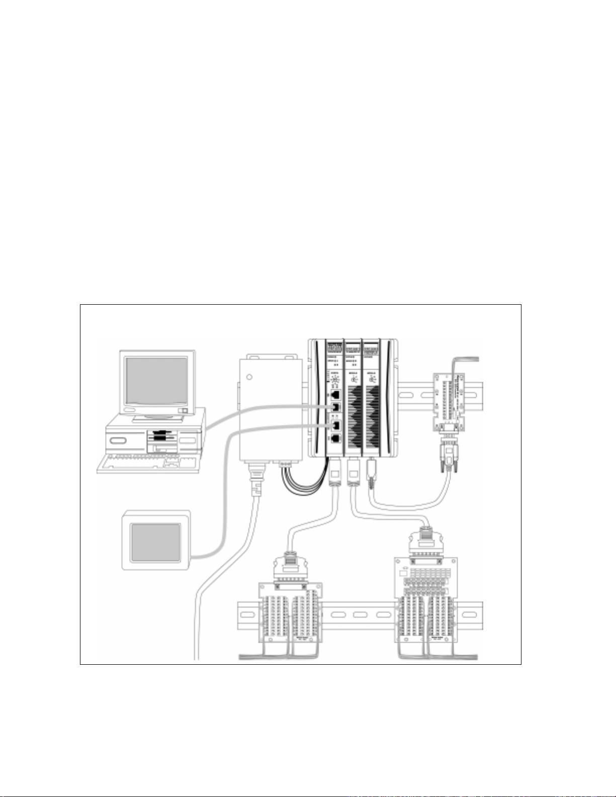
PC for AnaWin3 HMI
Software and/or LogicPro
Operator
Interface
Terminal
Power
Supply
PPC-2000
Assembly
TB50 for
Digital I/O
Encoder Input
Terminal Block
(EITB)
Analog Input
Terminal Board
(AITB)
Figure 1.1 System Diagram
4 Watlow Anafaze Doc.# 30002-00 Rev 2.3
Page 29

PPC-2000 User’s Guide Chapter 1: Overview
Table 1.1 PPC-2000 System Modules
Module Description
PPC-2010
PPC-2021, 2022 16 differential or 32 single-ended analog inputs
PPC-2024, 2025 8 or 16 highly isolated analog inputs
PPC-2030 4 encoder inputs and 4 analog outputs
PPC-2040
PPC-2050 8 analog outputs
PPC-2051 4 analog outputs
PPC-2061 16 relay outputs
PPC-2062 8 relay outputs
PPC-2070, 2071 8,16 120Vac inputs
PPC-2072, 2073 8,16 24V AC/DC inputs
Processor, 48 digital I/O, 2 serial ports,
1 counter/frequency input
32 configurable digital I/O, 2 counter/frequency
inputs
Table 1.2 PPC-2000 Terminal Boards and
Peripheral Modules
Terminal Board Description
PPC-IPS-2 International Power Supply, 120W
PPC-AITB-1 Analog Input Terminal Board
PPC-TB50-SCSI Terminal board for digital I/O
PPC-EITB-1 Encoder Input Terminal Board
Table 1.3 Analog Terminal Board Keys
Key
(Color Code)
PPC-KEY-20
(none)
PPC-KEY-30
(blue)
PPC-KEY-40
(black)
PPC-KEY-50
(red)
Doc.# 30002-00 Rev 2.3 Watlow Anafaze 5
Adapts AITB for:
Thermocouples (differential or single-ended)
Linear voltages (differential or single-ended)
Adapts AITB for 0-20mA linear current
(differential)
Adapts AITB for 0-20mA linear current
(single-ended)
Adapts AITB for 2-wire RTDs (differential) or
3-wire RTDs (differential)
Descriptions
Page 30
Chapter 1: Overview PPC-2000 User’s Guide
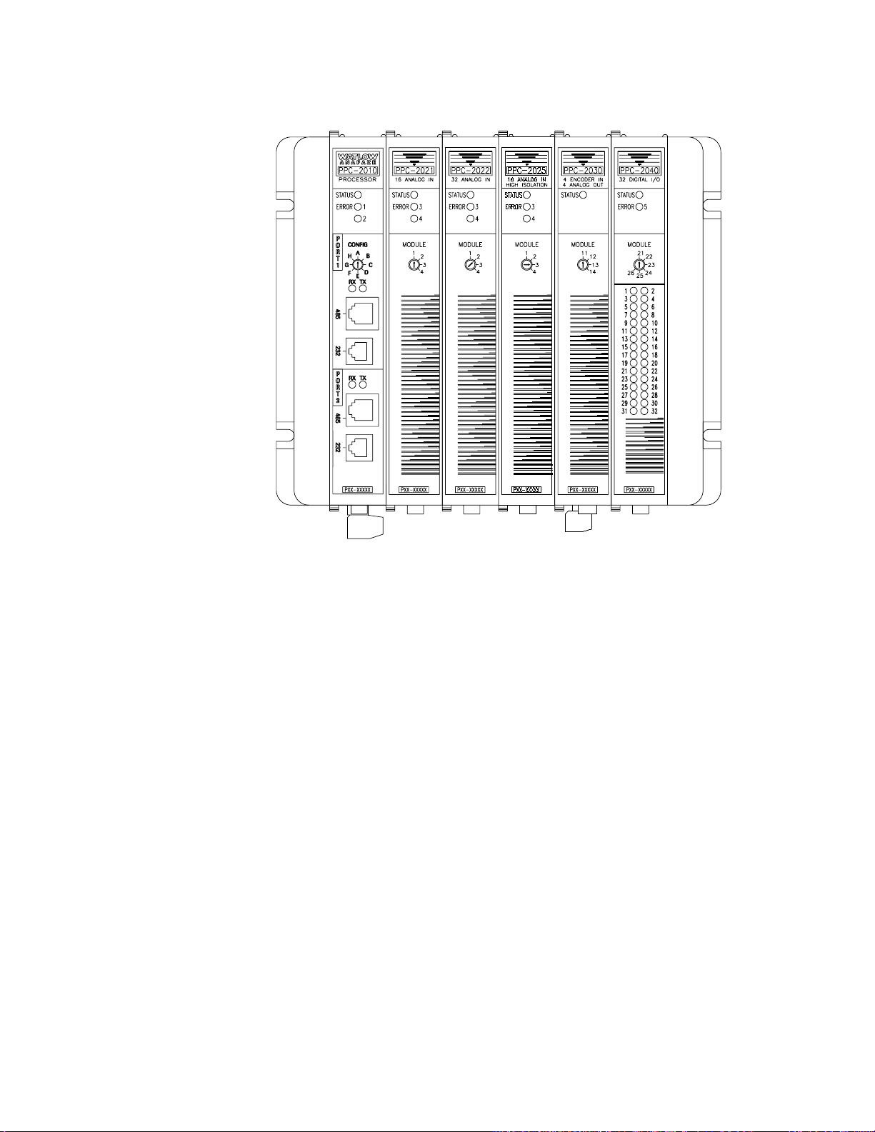
Figure 1.2 Sample PPC-2000 System
PPC-2000 Modules
The following sections describe the purpose and features of
each type of module available with the PPC-2000 system.
PPC-2010 Processor Module
The PPC-2010 processor module houses the system
microprocessor, memory and controller programs. Modular
communication ports support connections with a PC running
AnaWin3
connections with third-party operator interface panels or other
devices that communicate using Modbus protocol. Communications ports one and two may be used simultaneously.
Additional modules may be connected to the processor module’s
expansion bus to add capabilities to the PPC system.
Precision analog outputs can be provided using Serial Digital to
Analog Converters (SDAC). Each SDAC unit converts a control
output from the processor module to an analog voltage or
current signal. For more specific information, see
Analog-to-Digital Converter on page 9
and
LogicPro
or third-party interface software, and
SDAC Serial
.
6 Watlow Anafaze Doc.# 30002-00 Rev 2.3
Page 31

PPC-2000 User’s Guide Chapter 1: Overview
The PPC-2010 has 48 built-in digital I/O points. 24 points are
outputs only. 22 of these outputs are user configurable for PID
control, alarms or logic outputs. The other 2 outputs are
dedicated to system status and global alarm. The remaining 24
I/O points are individually configurable as either inputs or
outputs.
The following summarizes the processor’s features:
• 2 isolated communication ports
• Transmit/receive indicators
• Rotary switch for setting the Modbus network address
• 46 user configurable digital I/O
• System status and digital output overload indicators
• Real time clock
• Flash PROM and battery backed RAM
• Connects to terminal block board via 50-pin SCSI cable
PPC-2021 - 2022 Analog In Modules
The PPC-2021 and 2022 modules plug in to the module
expansion bus. The analog input modules support 16
differential inputs or 32 single-ended inputs, and accommodate
various sensors such as thermocouples (TCs), Resistive
Temperature Sensing Devices (RTDs) and linear transducers
using the terminal boards described later in this section.
• Supports TCs, RTDs and linear voltage and current
signals
• LED status indicator
• DIN rail/panel mount
• Connects to analog input terminal board via 50-pin SCSI
cable
PPC-2024 - 2025 Analog In High Isolation Modules
The PPC-2024 and 2025 modules plug in to the module
expansion bus. The high isolation analog input modules accept
8 or 16 differential analog inputs and accommodate various
sensors such as TCs, RTDs and linear transducers using the
terminal boards described later in this section.
• High voltage isolation capability
• Supports TCs, RTDs and linear voltage & current signals
• LED status indicator
• DIN rail/panel mount
• Connects to analog input terminal board via 50-pin SCSI
cable
Doc.# 30002-00 Rev 2.3 Watlow Anafaze 7
Page 32

Chapter 1: Overview PPC-2000 User’s Guide
PPC-2030 Encoder In Analog Out Module
The PPC-2030 is used in applications including monitoring and
controlling belt speeds, motor speeds, positioning, etc.
Four isolated analog outputs are jumper configurable for
current or voltage. These outputs may be used to provide
software selectable analog output signals to field devices.
Four counter inputs are used for interfacing to motor encoder
signals. The counters interface to both single-ended and
differential styles of encoder signals and count quadrature
signals for increased resolution, accuracy and direction.
PPC-2040 Digital I/O Module
Up to four PPC-2040 modules may be added to a PPC system.
Each module includes 32 digital I/O points which are
individually configurable as inputs or outputs and two counter
and frequency inputs.
PPC-2050 - 2051 Analog Out Modules
Up to four PPC-2050 and PPC-2051 modules may be added to
a PPC system. Modules include four or eight analog outputs.
PPC-2061 - 2062 Digital Out Relays Module
Up to six PPC-2060, PPC-2061, and PPC-2062 modules may be
added to a PPC system. The PPC-2061 features 16
electromechanical relays. These relays can switch AC or DC
loads. Two sets of eight relays each have a common. The PPC2062 features eight electromechanical relays.
PPC-2070 - 2073 Digital In Modules
Up to four modules of this type may be added to a PPC system.
Each module includes either 8 or 16 discrete inputs. The PPC2070 and 2071 modules accept 120Vac signals. The PPC-2072
and 2073 modules accept either 24Vac or 24Vdc.
PPC-2000 Terminal Boards
The following sections describe the terminal boards that
support field I/O connections to some modules.
PPC-AITB-1 Analog Input Terminal Board
The AITB is a compact field wiring interface for all analog
input modules. The AITB includes terminal blocks and
removable keys used for different types of inputs such as TCs,
RTDs and linear signals. For more information on these
signals, refer to PPC-KEY-01 through 04 in Table 1.1 on page
5. The keys allow easy configuration of the terminal block for
different types of inputs on different channels. The AITB is
DIN rail or panel mount compatible.
8 Watlow Anafaze Doc.# 30002-00 Rev 2.3
Page 33

PPC-2000 User’s Guide Chapter 1: Overview
PPC-EITB-1 Encoder Input Terminal Board
The EITB is a DIN rail or panel mountable terminal block card
which provides means to interface with motor encoders. Two
pulse inputs (single ended or differential, single or quadrature
phased) may be connected to the screw terminals. A 5Vdc
power source interconnect is provided to supply encoders.
PPC-TB50-SCSI 50-Pin Terminal Board
The TB50 connects to the Processor or Digital I/O module
through the SCSI connector. The terminal blocks interface to
digital I/O field wiring (sensors, actuators, relays, SSRs, etc.).
The TB50 has 48 input/output points. This terminal board is
DIN rail or panel mount compatible.
Additional Components
The following sections describe the optional SDAC module and
the PPC-IPS-2 power supply.
SDAC Serial Analog-to-Digital Converter
The SDAC peripheral module can be connected to a digital
output on the PPC-2010 Processor module. The SDAC converts
a special serial signal to an analog output.
One digital output is required for each SDAC module. Up to 5
SDACS may be connected. When using one or more SDACs, the
SDAC clock output from the PPC-2010 is used as well. The
Processor/SDAC clocks are tied together (the same clock line is
used for each SDAC).
PPC-IPS-2
Safety
WARNING!
The PPC-IPS-2 accepts power in two switch-selectable ranges:
88 to 132Vac and 176 to 264Vac at 47 to 440Hz. It has overload
and overvolt protection. The PPC-IPS-2 powers the PPC
system with 24Vdc and has 5Vdc available for powering loads.
Watlow Anafaze has made every effort to ensure the reliability
and safety of this product. In addition, we have provided
recommendations that will allow you to safely install and
maintain this controller. This product should not be used in any
manner not specified by Watlow Anafaze.
∫
Ensure that power has been shut off to your entire
process before you begin installation or servicing of
the controller.
Doc.# 30002-00 Rev 2.3 Watlow Anafaze 9
Page 34

Chapter 1: Overview PPC-2000 User’s Guide
CAUTION: This product is intended for indoor use only.
∫
WARNING!
Power, input or output circuits with hazardous
voltage levels should not have any live accessible
parts.
∫
WARNING!
External Safety Devices
In any application, failures can occur. These failures
can result in full control output (100% power), or the
occurrence of other output failures which can cause
damage to the controller, or to the equipment or
process connected to the controller. Therefore,
always follow good engineering practices, electrical
codes, and insurance regulations when installing and
operating this equipment.
External safety devices should be used to prevent potentially
dangerous and unsafe conditions upon equipment failure.
Always assume that this device can fail with outputs full-on, or
full-off, by the occurrence of an unexpected external condition.
∫
WARNING!
Always install high or low temperature protection in
installations where an over-temperature or undertemperature fault will present a potential hazard.
Failure to install external protection devices where
hazards exist can result in damage to equipment and
property as well as loss of human life.
Contact Watlow Anafaze immediately if you have any
questions about system safety or system operation.
10 Watlow Anafaze Doc.# 30002-00 Rev 2.3
Page 35

PPC-2000 User’s Guide Chapter 1: Overview
External Switch Disconnect
∫
WARNING!
Provide a labeled switch or circuit breaker connected
to the PPC-2000 power wiring as the means of
disconnection for servicing. Failure to do so could
result in damage to equipment and/or property, and/
or injury or death to personnel. The disconnect
should be located so that operators and technicians
can access it quickly and easily.
Battery Safety
ç
CAUTION!
Product Markings and Symbols
The battery used in this device may result in a fire or
chemical burn hazard if mistreated. Do not
disassemble, heat above 100˚C (212˚F) or incinerate.
Dispose of used battery properly. Keep away from
children.
This symbol indicates that the products meets the essential
requirements of applicable European Union Directives.
CUS
LISTED
Î
Doc.# 30002-00 Rev 2.3 Watlow Anafaze 11
This symbol indicates that the product is listed by
Underwriters Laboratory and Canadian Underwriters
Laboratory.
The terminals adjacent to this symbol should be connected to
DC voltage only.
Page 36

Chapter 1: Overview PPC-2000 User’s Guide
12 Watlow Anafaze Doc.# 30002-00 Rev 2.3
Page 37

Hardware Installation
This section describes how to install your PPC system
hardware. It provides detailed instructions for each component
and peripheral item. Read this chapter before installing your
PPC-2000 system.
Power Supply Requirements
Watlow Anafaze provides the PPC-IPS2 power supply for the
PPC-2000 system. This unit supplies sufficient current for a
processor and various combinations of I/O modules. For
specification information on the power supply, refer to Chapter
7, Specifications.
Any power supply connected to the PPC-2000 should meet
these requirements:
2
• Transformer isolation
• Reliable operation without noise or feedback
• Provides specified voltage and current
• UL Listed
• Suitable for use in a 60°C ambient environment
Regardless of which power supply you use, you must provide
sufficient current in the specified voltage range, 10-28Vdc. The
current requirement depends on the type and number of
modules used. A separate power supply is required for each
controller. Use Table 2.1 on page 14 to calculate the current
requirements for your system.
Doc.# 30002-00 Rev 2.3 Watlow Anafaze 13
Page 38

Chapter 2: Hardware Installation PPC-2000 User’s Guide
Table 2.1 Power Supply Current
Requirements at 12Vdc
Module Number
of
modules
Current
(startup)
per
Current
module
PPC-2010 1 x 250mA = 250mA
PPC-202x
(max. 4)
PPC-2030
(max. 4)
PPC-2040
(max. 6)
PPC-2050
PPC-2051
(max. 4)
PPC-206x
(max. 6)
PPC-207x
(max. 4)
Total Number of
Modules
(max. 10)
x 390mA =
x 900mA =
x 300mA =
xx800mA
500mA
x 250mA =
x 100mA =
total
current
required
=
=
=
Table 2.2 Power Supply Current Requirements
at 24Vdc
Module Number
of
modules
PPC-2010 1 x 125mA = 125mA
PPC-202x (max. 4) x 195mA =
PPC-2030 (max. 4) x 450mA =
PPC-2040 (max. 6) x 150mA =
PPC-2050
PPC-2051
(max. 4)
PPC-206x (max. 6) x 125mA =
PPC-207x (max. 4) x 50mA =
Total Number of
Modules (max. 10)
x
Current
(startup)
per
module
400mA
250mA =
total
current
required
Current
=
14 Watlow Anafaze Doc.# 30002-00 Rev 2.3
Page 39

PPC-2000 User’s Guide Chapter 2: Hardware Installation
∫
WARNING!
The PPC is designed to operate on 12-28Vdc.
Connection to a power source other than this will
cause damage to the PPC.
To avoid electrical shock, correctly connect the
power supply’s earth ground.
Mounting the Power Supply
Mount the hardware in an area free of moisture or corrosive
chemicals. Mount the power supply vertically with adequate
vent space. Locate the power supply for the PPC such that the
AC supply and DC connections to the PPC may be made. The
PPC-IPS-2 can be DIN rail or screw mounted. Refer to Figure
2.1 for power supply mounting clearances. All dimensions are
measured in inches.
2.5 in. min.
Air Flow Space
ADJ
1.2 in.
V2 COM COM V1 V1 V1
L N
1.97 in.
3.1 in.
Figure 2.1 PPC-IPS-2 DIN Mounting
Dimensions
Doc.# 30002-00 Rev 2.3 Watlow Anafaze 15
Page 40

Chapter 2: Hardware Installation PPC-2000 User’s Guide
All
Vented
1.97 in.
1.32 in.
115
0.93 in.
0.24 in.
7.5 in. 7.84 in.
0.10 in.
Figure 2.2 PPC-IPS-2 Panel Mounting
Dimensions
To DIN rail mount the PPC-IPS-2:
1. Locate a space with sufficient room for the power supply
and connecting wires. Refer to Figure 2.1 on page 15.
2. Install a section of DIN rail.
3. Hook the top of the DIN rail latch over the DIN rail such
that the spring is under the lip of the rail.
4. Push down on the power supply, compressing the spring
then rock the bottom of the latch onto the rail.
To panel mount the PPC-IPS-2:
1. Locate a space with sufficient room for the power supply
and connecting wires. Refer to Figure 2.2.
2. Mark the mounting holes. See Table 2.3 on page 16.
3. Drill and tap the mounting holes.
4. Place the power supply such that the holes are aligned,
insert the screws and tighten them
Table 2.3 Power Supply Screw Mounting
PPC-IPS-2
Number of Screws 3
Drill and tap size #6
16 Watlow Anafaze Doc.# 30002-00 Rev 2.3
Page 41

PPC-2000 User’s Guide Chapter 2: Hardware Installation
Hardware Configuration
In order for multiple PPC modules to function together, each
needs to be addressed correctly. Some of the PPC modules may
require jumper or switch settings to work with field input and
output devices. The following sections describe the
configuration options and procedures.
Module Addresses
Each module in a PPC assembly must have a unique address.
The PPC-2010 module is fixed as module address 0 in the
firmware. The other modules’ addresses are set with rotary
switches on the face of each module. Set a unique address on
each module by turning the arrow to an appropriate address
number. See Figure 2.3.
ç
CAUTION!
NOTE!
Figure 2.3 Sample Addresses
Table 2.4 on page 18 lists the maximum number allowable of
each type of module per system, as well as the available
address settings. Pay close attention when using more than one
module of a particular type in a system. For example, one PPC
system allows up to four analog input modules (PPC-2021 -
2025) and each must have a unique address setting, as shown
in Figure 2.3.
If address settings are changes, modules added or
removed after the system has been initialized,
modules may not function correctly. To assure proper
operation, perform a RAM Clear after changing the
number of modules or address settings in a PPC
system. Refer to Chapter 4, Resetting Closed-Loop
Control Parameters on page 156.
It may be useful to label each module with the address
you select.
Doc.# 30002-00 Rev 2.3 Watlow Anafaze 17
Page 42

Chapter 2: Hardware Installation PPC-2000 User’s Guide
Table 2.4 System Modules and Addressing
Module Max.
#*
2010 (PROCESSOR) 1 0 (not switch selectable)
2021, 2022
(ANALOG IN)
2023, 2024, 2025
(ANALOG IN
HIGH ISOLATION)
2030
(ENCODER IN
ANALOG OUT)
2040
(DIGITAL I/O)
2050, 2051
(ANALOG OUT)
2061, 2062
(DIGITAL OUT)
2070, 2071
(DIGITAL IN, 120Vac)
2072, 2073
(DIGITAL IN, 24Vac/DC)
4 1-4
4 11-14
6 21-26,
4 31-34
6 41-46
4 51-54
Rotary Switch
Address Range
* Maximum number of this type of module in a system
PPC-2010 Jumper Settings
Jumper settings in the PPC-2010 select whether the
communication lines are terminated or not. Each
communication port is configured separately. For installation
information, refer to Connecting RS-485 Communications on
page 81.
Wear a grounding strap and place components on static-free
grounded surfaces only. Locate jumpers 1 and 2. Table 2.5
describes the PPC-2010 jumper configuration. Install the
jumper in the orientation shown in Figure 2.4 on page 19.
Table 2.5 PPC-2010 Processor Module Jumpers
Port Jumper #
1 JU1 A B
2 JU2 A B
Terminated
Position
Unterminated
Position
18 Watlow Anafaze Doc.# 30002-00 Rev 2.3
Page 43

PPC-2000 User’s Guide Chapter 2: Hardware Installation
Flash memory
Chip (firmware)
Notch
Termination
Jumper
Port 1
JU1
B A
Not T erminated
Position
JU1
B A
B A
JU2
Figure 2.4 PPC-2010 Jumpers
Battery
Notch
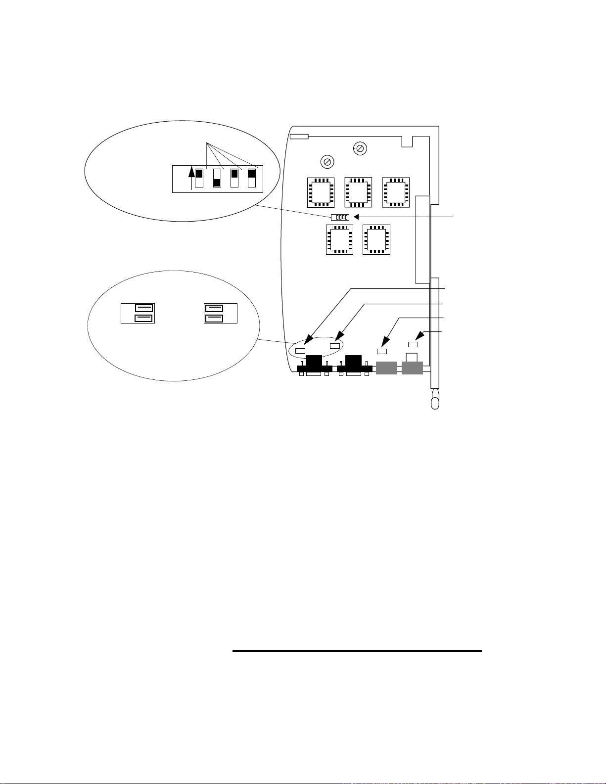
PPC-2030 Dip Switch Settings
Switch settings in the PPC-2030 determine whether encoder
inputs accept single phase or quadrature encoder signals. Each
of the four inputs is configured individually, therefore single
phase and quadrature inputs may be mixed in a module.
Wear a grounding strap and place components on static-free
grounded surfaces only. Locate switch bank 1 near the center
of the PPC-2030 module. Refer to Figure 2.5 on page 20. Set
each switch for the corresponding input to the single phase (on)
or quadrature (off) position. The switch is on when in the
direction indicated by the arrow.
ç
CAUTION!
Be sure to take antistatic precautions.
Doc.# 30002-00 Rev 2.3 Watlow Anafaze 19
Page 44
Chapter 2: Hardware Installation PPC-2000 User’s Guide
{Improve illustration. More like 2.6 and 2.7.}
Counter Input Number
Single Phase
Quadrature
51
SV4
Analog Output Jumpers
. . .
. . .
v
i
Voltage
Position
Current
Position
432
1
S1
. . . . . . . . . . . . . . . .
. . . . . . . . . . . . . . . .
. . . . . . . . . . . . . . . .
. . .
. . .
v
i
...
...
...
JU1
...
...
JU2
...
Figure 2.5 PPC-2030 Jumpers and Switches
...
...
JU4
JU3
Dip Switch
JU1 (Output 4)
JU2 (Output 3)
JU3 (Output 2)
JU4 (Output 1)
PPC-2030 Jumper Settings
Each of the four analog outputs on the PPC-2030 may be
configured either as a voltage output or a current output. A
mixture of current and voltage outputs may be used on a
particular module. The jumpers only determine if the output
signal is current or voltage. The actual span of the signal is
software selectable. See Output Type in Channels on page 115
for the various analog output signal settings.
Locate Jumpers 1 through 4. Table 2.6 on page 21 describes the
analog output jumper configuration. Install the jumper in the
orientation shown in Figure 2.5.
ç
CAUTION!
20 Watlow Anafaze Doc.# 30002-00 Rev 2.3
Incorrectly installing the jumper may damage the
PPC-2030 module.
Page 45

PPC-2000 User’s Guide Chapter 2: Hardware Installation
Table 2.6 PPC-2030 Analog Output Jumpers
Analog
Output
1 JU4 0-20mA 0-10Vdc
2 JU3 0-20mA 0-10Vdc
3 JU2 0-20mA 0-10Vdc
4 JU1 0-20mA 0-10Vdc
* Listed values are maximum ranges. Other ranges within these
limits may be selected in software.
PPC-2040 Jumper Settings
Each of the counter inputs on the PPC-2040 can be configured
for single phase or quadrature input. Jumper positions
determine the counter input configuration. To select single
phase or quadrature, see Table 2.7 and Figure 2.6 to determine
which jumper to set and appropriate position.
Table 2.7 PPC-2040 Counter Input Jumpers
Counter
Input
Jumper #
Jumper
PPC-2040
i (current)
position*
Single Phase
Position
V (volt)
position*
Quadrature
Position
1 JU1 A B
2 JU2 A B
JU2
JU1
A B
A B
Figure 2.6 PPC-2040 Jumper Settings
Doc.# 30002-00 Rev 2.3 Watlow Anafaze 21
Page 46

Chapter 2: Hardware Installation PPC-2000 User’s Guide
PPC-205x Jumper Settings
Each of the analog outputs on the PPC-205x modules may be
configured either as a voltage output or a current output. A
mixture of current and voltage outputs may be used on a
particular module. The jumpers only determine if the output
signal is current or voltage. The actual span of the signal is
software selectable. See Heat/Cool Output Type in Channels
section on page 119 for the various analog output signal
settings.
To configure an output, see Table 2.8 on page 22 and Figure 2.7
on page 23 to determine which jumper to set. Set the jumper in
the indicated position and orientation.
Table 2.8 PPC-205x Analog Out Jumpers
Analog
Output
1 JU1 JU1 0-20mA 0-10Vdc
2 JU2 JU3 0-20mA 0-10Vdc
3 JU3 JU5 0-20mA 0-10Vdc
4 JU4 JU7 0-20mA 0-10Vdc
5 JU5 n/a 0-20mA 0-10Vdc
6 JU6 n/a 0-20mA 0-10Vdc
7 JU7 n/a 0-20mA 0-10Vdc
8 JU8 n/a 0-20mA 0-10Vdc
Jumper
PPC-2050
* Listed values are maximum ranges. Other ranges within these
limits may be selected in software.
Jumper
PPC-2051
i (current)
Position*
v (voltage)
Position*
22 Watlow Anafaze Doc.# 30002-00 Rev 2.3
Page 47

PPC-2000 User’s Guide Chapter 2: Hardware Installation
Analog Output Jumpers
. . .
. . .
I
Voltage
Position
V
. . .
. . .
I
Current
Position
V
JU7
JU6
JU5
JU8
I
V
I
I
V
V
JU4
JU3
JU2
JU1
I
I
I
V
I
I
V
V
V
V
JU8 (2050: Output 8)
JU7 (2050: Output 7, 2051: Output 4)
JU6 (2050: Output 6)
JU5 (2050: Output 5, 2051: Output 3)
JU4 (2050: Output 4)
JU3 (2050: Output 3, 2051: Output 2)
JU2 (2050 Output 2)
JU1 (Output 1)
Figure 2.7 PPC-205x Jumpers
Doc.# 30002-00 Rev 2.3 Watlow Anafaze 23
Page 48

Chapter 2: Hardware Installation PPC-2000 User’s Guide
Module Assembly
Modules should be assembled prior to mounting. The processor
module is always the first module (left side) on a PPC system.
To connect other modules, use the following procedure.
ç
CAUTION!
ç
CAUTION!
To avoid damaging your PPC system, never connect
or disconnect modules that are powered.
PPC modules contain sensitive electronic
components. Be sure to observe ESD safety
precautions such as wearing a ground strap.
1. Make sure the red top and bottom module latches on the
module to be added are in the unlocked position (pushed
toward the back of the module. Refer to Figure 2.8.
Back
Module
top
latch
(unlocked)
Module
top
latch
(locked)
Front
Figure 2.8 Assembled Modules Top View
24 Watlow Anafaze Doc.# 30002-00 Rev 2.3
Page 49

PPC-2000 User’s Guide Chapter 2: Hardware Installation
2. Align the 4 interconnect tabs and their related slots, as
well as the module expansion bus connector.
Front
Module
bottom
latch
(locked)
Module
bottom
latch
Back
(unlocked)
Figure 2.9 Assembled Modules Bottom View
Slot
Tab
Module
bottom
latch
(locked)
Module
bottom
latch
(unlocked)
Figure 2.10 Modules Bottom/Side View
3. Gently press the modules together while observing the
alignment of the tabs and slots, as well as the pins on the
expansion bus connector.
4. When the module is properly seated, close the module
latches on the processor by pushing the latch toward the
front of the module. The modules are properly locked when
there is a firm connection with no rocking or shifting.
5. Repeat these steps for any additional modules. When
there are no additional modules, install the right end cap
in a similar manner.
Doc.# 30002-00 Rev 2.3 Watlow Anafaze 25
Page 50

Chapter 2: Hardware Installation PPC-2000 User’s Guide
Module Disassembly
To separate modules, reverse the procedure in Module
Assembly on page 24. When separating modules, gently rock
and pull the modules apart.
ç
CAUTION!
To avoid damaging your PPC system, never connect
or disconnect modules that are powered.
Mounting Modules
Once the modules have been assembled, the PPC system may
be mounted on a DIN rail or fastened directly to a vertical
surface inside an electrical cabinet or other enclosure that
requires a key or tool to open, or that has a safety interlock
system. Consult Table 7.2 on page 230 and Figure 7.1 on page
230 to determine mounting hole spacing and installed
clearances. See Figure 1.1 on page 4 for a sample configuration
of PPC system hardware.
∫
WARNING!
Install the PPC-2000 in a controlled environment,
relatively free of contaminants, to
reduce the risk of fire or electric shock.
ç
CAUTION!
NOTE!
26 Watlow Anafaze Doc.# 30002-00 Rev 2.3
The controller may function incorrectly if the ambient
temperature exceeds the operating specification.
Make sure the air temperature surrounding the
controller does not exceed 140°F (60°C).
During wiring and cabinet assembly, prevent debris
from falling inside the PPC by removing the unit from
the area, or cover the ventilation holes on the PPC
system.
Page 51

PPC-2000 User’s Guide Chapter 2: Hardware Installation
DIN Rail Mounting
1. Each module in the assembly has a DIN rail latch. Pull all
the latches to the open position. See Figure 2.11.
DIN Rail Latch
(closed)
DIN Rail Latch
(open)
Figure 2.11 DIN Rail Latches
2. Place the module assembly on the upper lip of the DIN
rail; push the lower side of the assembly over the lower lip
of the DIN rail. See Figure 2.12.
Upper lip of
DIN Rail
DIN Rail Latch
(open)
Push to lock
Figure 2.12 Mounting Assembled PPC
Modules on a DIN rail (side)
3. Push the DIN rail latches up and under the lower lip of the
DIN rail.
Doc.# 30002-00 Rev 2.3 Watlow Anafaze 27
Page 52

Chapter 2: Hardware Installation PPC-2000 User’s Guide
Panel Mounting
The PPC modules may be panel mounted using the mounting
holes located on the end plates. The width of a system varies
depending on the number of modules. Consult Figure 7.1 on
page 230 to determine installed clearances.
To panel mount the modules:
1. Locate a space with sufficient room for the appropriate
number of modules and connecting wires. Refer to Figure
7.1 on page 230 for a system footprint and dimensions.
2. The mounting holes are located on the end caps of the
module assembly. Mark each mounting hole.
3. Drill and tap the four #10 mounting holes.
4. Place the modules such that the holes are aligned, insert
the screws and tighten them.
Mounting Terminal Boards
Terminal boards support interfacing field I/O devices with the
PPC modules. All terminal boards may be DIN rail or panel
mounted. The following sections provide procedures for
mounting the terminal boards.
There are smaller holes on each terminal board that may be
used to secure wiring with tie wraps.
Refer to Figure 2.13 on page 29 for AITB dimensions.
Refer to Figure 2.14 on page 30 for EITB dimensions.
Refer to Figure 2.15 on page 31 for TB50 dimensions.
28 Watlow Anafaze Doc.# 30002-00 Rev 2.3
Page 53

PPC-2000 User’s Guide Chapter 2: Hardware Installation
5.756"
(146 mm)
5.1"
(128 mm)
For more detailed specification information, refer to Chapter 7,
Specifications.
3.6"
(91 mm)
2.0"
(51 mm)
4.70" 5.10" L
(130 mm)(119 mm)
2.6"
(66 mm)
4.0" W
(102 mm)
Figure 2.13 AITB Dimensions / Clearances
Doc.# 30002-00 Rev 2.3 Watlow Anafaze 29
Page 54

Chapter 2: Hardware Installation PPC-2000 User’s Guide
2.2 in.
(56 mm)
3.4 in.
(86 mm)
1.6 in.
(41 mm)
2.0 in. W
(51 mm)
3.8 in. L
(97 mm)
Figure 2.14 EITB Dimensions / Clearances
30 Watlow Anafaze Doc.# 30002-00 Rev 2.3
Page 55

PPC-2000 User’s Guide Chapter 2: Hardware Installation
3.6 in.
(91 mm)
2.3 in.
(58 mm)
DIN Rail Mounting
3.4 in.
(86 mm)
2.6 in.
(66 mm)
4.2 in.W
(102 mm)
4.1in. L
(104 mm)
Figure 2.15 TB50 Dimensions / Clearances
All factory terminal boards snap onto a DIN rail. A TB50 is
shown in the following figures for illustration purposes only.
To install a terminal board on a DIN rail, place the hook side of
the mounting mechanism over one of the DIN rail lips and snap
the board over the other lip.
Doc.# 30002-00 Rev 2.3 Watlow Anafaze 31
Page 56

Chapter 2: Hardware Installation PPC-2000 User’s Guide
DIN Rail Removal
Hook side
Figure 2.16 TB50 Mounted on DIN Rail (Front)
Place a flat blade screw driver through the slot in the board and
hook the blade into the snap latch. Pry the snap latch away
from the DIN rail lip and repeat for the other side. See Figure
2.17.
Removal
catch for
screwdriver
DIN Rail
snap latch
Hook side
Figure 2.17 TB50 Mounted on DIN Rail (Side)
32 Watlow Anafaze Doc.# 30002-00 Rev 2.3
Page 57

PPC-2000 User’s Guide Chapter 2: Hardware Installation
Panel Mounting
NOTE!
When panel mounting terminal boards, remove the
DIN rail brackets before mounting the boards.
Standoff
Figure 2.18 TB50 Panel Mounted
Stand-offs are provided for all terminal boards.
1. Remove the DIN rail mounting brackets from terminal
board.
2. Select a location with enough clearance for the board and
its SCSI cable. Refer to Figure 2.15 on page 31 for installed
clearances.
3. When a location has been determined for board, mark the
four mounting holes.
4. Drill and tap the four #6-32 mounting holes.
5. Place the terminal board so the standoffs are aligned with
the holes. insert the screws in to the standoffs and tighten
them.
Doc.# 30002-00 Rev 2.3 Watlow Anafaze 33
Page 58

Chapter 2: Hardware Installation PPC-2000 User’s Guide
Mounting an SDAC Module
Follow these steps to install the SDAC module:
1. Select a location for installation. The SDAC is designed for
wall mounting. It should be installed as close to the
controller as possible.
2. Mark and drill four holes for screw mounting. Use the diagrams below for the correct locations.
3. Install the unit with the four #4 screws.
System Wiring
3.60 in.
(91 mm)
Electrical
connections
Electrical
connections
5.40 in.
(137 mm)
4.68 in.
(119 mm.)
3.00 in.
(76 mm)
1.75 in.
(44 mm)
Figure 2.19 SDAC Dimensions
Successful installation and operation of the control system can
depend on placement of the components and on selection of the
proper cables, sensors, and peripheral components.
Routing and shielding of sensor wires and proper grounding of
components can insure a robust control system. This section
includes wiring recommendations, instructions for proper
grounding and noise suppression, and considerations for
avoiding ground loops.
ç
CAUTION!
34 Watlow Anafaze Doc.# 30002-00 Rev 2.3
Never route low power circuits next to high power AC
wiring. Instead, physically separate high power
circuits from the controller. If possible, install high
voltage AC power circuits in a separate panel.
Page 59

PPC-2000 User’s Guide Chapter 2: Hardware Installation
ç
CAUTION!
Power, input or output circuits with hazardous voltage
levels should not have any live accessible parts.
Wiring Recommendations
Keep the following guidelines in mind when selecting wires and
cables:
• Use stranded wire. (Solid wire can be used for fixed
service; but it makes intermittent connections when you
move it for maintenance.)
• Use #20 AWG TC extension wire. Larger or smaller sizes
may be difficult to install, may break easily, or may cause
intermittent connections.
• Use shielded wire. (The electrical shield protects the
signals and the PPC-2000 from electrical noise.) Connect
only one end of the shield to earth ground.
• Use copper wire for all connections other than
thermocouple sensor inputs.
See Table 2.9 for cable recommendations.
Table 2.9 Cable Recommendations
Function Mfr. P/N
Analog Inputs
RTD Inputs
TC Inputs TC Ext. Wire 2 20
Digital PID Outputs
and Digital I/O
Analog Outputs
Computer
Communication:
RS232, RS422,
RS485, or 20mA
Noise Suppression
The PPC-2000’s outputs are designed to drive resistive loads.
Open collector outputs can drive solid state relays. These relays
may in turn operate more inductive types of loads such as
Belden #9154
Belden #8451
Belden #8772
Belden #9770
Belden #9539
Belden #9542
Belden #9154
Belden #8451
Belden #9729
Belden #9730
Belden #9842
Belden #9843
Belden #9184
No. of
Wires
2
2
3
3
9
20
2
2
4
6
4
6
4
AWG
Gauge
20
22
20
22
24
24
20
22
24
24
24
24
22
Max.
Length
4000 ft.
4000 ft.
6000 ft.
Doc.# 30002-00 Rev 2.3 Watlow Anafaze 35
Page 60

Chapter 2: Hardware Installation PPC-2000 User’s Guide
electromechanical relays, alarm horns and motor starters.
Such devices may generate electromagnetic interference (EMI
or noise). If the controller is placed close to sources of EMI, it
may not function correctly. Below are some tips on how to
recognize and avoid problems with EMI.
Symptoms of RFI/EMI
If your controller displays the following symptoms, suspect
EMI:
• Measured values for analog inputs fluctuate or are
incorrect.
• Open collector outputs fail.
• The watchdog time out LED on the Processor Module
lights.
EMI may also damage the digital output circuit—so digital
outputs will not turn on. If the digital output circuit is
damaged, return the controller to Watlow Anafaze for repair.
Avoiding Noise Problems
To avoid RFI/EMI noise problems:
• PPC-2022 32 analog input module must be used with
isolated (ungrounded) thermocouples only.
• PPC-2022 32 analog input module should not be used with
thermocouples that are embedded within heaters as some
cartridge heaters are constructed.
• Separate the 120 or 240Vac power leads from the low level
input and output leads connected to the controller. Don't
run the digital I/O or control output leads in bundles with
120Vac wires.
• Where possible, use solid state relays (SSRs) instead of
electromechanical (EM) relays. If you must use EM relays,
try to avoid mounting them in the same panel as the PPC2000 series equipment.
• When switching an inductive load such as an
electromechanical relay or solenoid, install a snubber
across the load. Use a 0.01 microfarad capacitor rated at
1000Vac (or higher) in series with a 47 Ohm, 0.5 watt
resistor across the NO contacts of the relay load. See
Chapter 2, Connecting to the Relay Outputs on the PPC206x on page 70 for specific instructions on using snubbers
with the PPC-206x modules.
36 Watlow Anafaze Doc.# 30002-00 Rev 2.3
Page 61

PPC-2000 User’s Guide Chapter 2: Hardware Installation
• You can use other voltage suppression devices, but they
are not usually required. For instance, you can place a
metal oxide varistor (MOV) rated at 130Vac for 120Vac
control circuits across the load, which limits the peak AC
voltage to about 180Vac. You can also place a transorb
(back to back zener diodes) across the digital output,
which limits the digital output voltage.
The above steps will eliminate most EMI/RFI noise problems.
If you have further problems or questions, please contact
Watlow Anafaze.
Avoiding Ground Loops
Ground Loops can cause instrument errors or malfunctions. Do
not connect any of the following pins to each other or to earth
ground:
• DC power common terminals on the PPC power supply
and PPC-2010 Processor Module
• DC common terminals on TB50s
• Analog common terminals on AITBs
• Signal common terminals on the EITB or other devices
connected to the encoder inputs on a PPC-2030
Watlow Anafaze strongly recommends that you:
• Isolate outputs through solid state relays, where possible.
• Isolate RTDs or “bridge” type inputs from ground.
Connecting I/O to the PPC-2010
A TB50 connects to the PPC-2010 Processor module through
the 50 pin SCSI connector. Refer to Figure 2.20 on page 38. The
terminal block interfaces to field wiring of the digital I/O
(sensors, actuators, relays, SSRs, etc.).
Connecting the TB50 to the PPC-2010 Module
Refer to Figure 2.20 on page 38. Connect the SCSI connector
from the PPC-2010 module to the TB50.
Doc.# 30002-00 Rev 2.3 Watlow Anafaze 37
Page 62

Chapter 2: Hardware Installation PPC-2000 User’s Guide
50-pin SCSI
Connector
TB50
pin 1
PPC-2010
Bottom View
Figure 2.20 PPC-2010 Connection to TB50
NOTE!
If more than one module in the PPC system is
connected to a terminal board using a 50-pin SCSI
connector, label each end of each cable and each
terminal board with the address of the module to
which it should be connected.
TB50 Connections
Connect digital inputs and digital outputs for control signals,
alarms, and digital field I/O to the TB50. When connected to
the PPC-2010 Processor module, one pulse signal input and up
to five SDAC analog output modules can be connected to the
TB50. Table 2.10 on page 39 shows the TB50 pinout for use
with the PPC-2010.
Use 14 to 22 AWG wire. When making connections, tighten to
0.5 to 0.6 Nm, or 4.5 to 5.4 inch-pound.
38 Watlow Anafaze Doc.# 30002-00 Rev 2.3
Page 63

PPC-2000 User’s Guide Chapter 2: Hardware Installation
Table 2.10 Processor Module I/O Connections
Module I/O Number
Digital In/Out 1
Counter 1
Frequency 1
Digital In/Out 2 2 PPC1: Proc 0.0.2
Digital In/Out 3 3 PPC1: Proc 0.0.3
Digital In/Out 4 4 PPC1: Proc 0.0.4
Digital In/Out 5 5 PPC1: Proc 0.0.5
Digital In/Out 6 6 PPC1: Proc 0.0.6
Digital In/Out 7 7 PPC1: Proc 0.0.7
Digital In/Out 8 8 PPC1: Proc 0.0.8
Digital In/Out 9 9 PPC1: Proc 0.0.9
Digital In/Out 10 10 PPC1: Proc 0.0.10
Digital In/Out 11 11 PPC1: Proc 0.0.11
Digital In/Out 12 12 PPC1: Proc 0.0.12
Digital In/Out 13 13 PPC1: Proc 0.0.13
Digital In/Out 14 14 PPC1: Proc 0.0.14
Digital In/Out 15 15 PPC1: Proc 0.0.15
Digital In/Out 16 16 PPC1: Proc 0.0.16
Digital In/Out 17 17 PPC1: Proc 0.0.17
Digital In/Out 18 18 PPC1: Proc 0.0.18
Digital In/Out 19 19 PPC1: Proc 0.0.19
Digital In/Out 20 20 PPC1: Proc 0.0.20
Digital In/Out 21 21 PPC1: Proc 0.0.21
Digital In/Out 22 22 PPC1: Proc 0.0.22
Digital In/Out 23 23 PPC1: Proc 0.0.23
Digital In/Out 24 24 PPC1: Proc 0.0.24
Digital Out 25 25 PPC1: Proc 0.0.25
Digital Out 26 26 PPC1: Proc 0.0.26
Digital Out 27 27 PPC1: Proc 0.0.27
Digital Out 28 28 PPC1: Proc 0.0.28
Digital Out 29 29 PPC1: Proc 0.0.29
Digital Out 30 30 PPC1: Proc 0.0.30
Digital Out 31 31 PPC1: Proc 0.0.31
Digital Out 32 32 PPC1: Proc 0.0.32
Digital Out 33 33 PPC1: Proc 0.0.33
Digital Out 34 34 PPC1: Proc 0.0.34
TB-50
Terminal
1
AnaWin3 Name
(Dig I/O Spreadsheet)
PPC1:Proc 0.0.1
PPC1:Proc 0.1.1C
PPC1: Proc 0.2.1 F
1
2
Doc.# 30002-00 Rev 2.3 Watlow Anafaze 39
Page 64

Chapter 2: Hardware Installation PPC-2000 User’s Guide
Module I/O Number
Digital Out 35 35 PPC1: Proc 0.0.35
Digital Out 36 36 PPC1: Proc 0.0.36
Digital Out 37 37 PPC1: Proc 0.0.37
Digital Out 38 38 PPC1: Proc 0.0.38
Digital Out 39 39 PPC1: Proc 0.0.39
Digital Out 40 40 PPC1: Proc 0.0.40
Digital Out 41
SDAC Out 41
Digital Out 42
SDAC Out 42
Digital Out 43
SDAC Out 43
Digital Out 44
SDAC Out 44
Digital Out 45
SDAC Out 45
Digital Out 46
SDAC Clock
Global Alarm 47 PPC1: Proc 0.0.47
CPU Watchdog 48 PPC1: Proc 0.0.48
Com (DC Common for
Input Return)
TB-50
Terminal
41 PPC1: Proc 0.0.41
42 PPC1: Proc 0.0.42
43 PPC1: Proc 0.0.43
44 PPC1: Proc 0.0.44
45 PPC1: Proc 0.0.45
46 PPC1: Proc 0.0.46
49,50 N/A
AnaWin3 Name
(Dig I/O Spreadsheet)
1
1.
The name is shown for the first PPC-2000 in the system. See Digital I/O on page
132 for a complete explanation of digital I/O names.
2.
Both count and frequency are measured for the pulse input. See Inputs on page
127 for an explanation of analog input names.
Connecting Digital Inputs
The PPC-2010 module can accept digital inputs. When the
resistance of an input device is 27 kOhm or greater, the input
is considered off by the PPC-2000. When the resistance is 1
kOhm or less, the input is considered on.
To install a switch as a digital input, connect one lead to the DC
Common input return on the TB50. Connect the other lead to
the desired digital input on the TB50. Refer to Table 2.10 on
page 39 for screw terminal numbering.
Use the Digital I/O parameters to configure digital inputs.
Refer to Digital I/O on page 132.
40 Watlow Anafaze Doc.# 30002-00 Rev 2.3
Page 65

PPC-2000 User’s Guide Chapter 2: Hardware Installation
{Add examples with transistor inputs on
digital and pulse inputs.}
Digital
Input
Device
Digital In
Com
TB50
Figure 2.21 Wiring Digital Inputs
Connecting Counter or Frequency Inputs
PPC-2010 module accepts a single-phase pulse signal from
devices such as encoders. Counts and frequencies of the inputs
may be scaled with user selectable parameters. See Setting up
User Selectable Linear Inputs on page 98 for more information.
The PPC-2010 module can accommodate encoder signals up to
24Vdc. The following figures illustrate connecting encoders:
Encoder
Figure 2.22 Encoder with 5Vdc TTL Signal
Connecting Digital Outputs
The digital outputs sink current from a load connected to the
controller’s power supply, or another power supply referenced
to the PPC-2000 power common. Do not exceed +24 volts on the
outputs.
If you must tie the external load to ground, or if you cannot
connect it as shown in Figure 2.23 through Figure 2.25, use a
solid state relay to drive your load.
The outputs conduct current when they are LOW or ON. The
maximum current sink capability is 100mA at 24Vdc. They
cannot ‘source’ current to a load.
TB50
PPC-2010
+5Vdc
10 kOhm
Frequency/Counter Input
Com
Doc.# 30002-00 Rev 2.3 Watlow Anafaze 41
Page 66

Chapter 2: Hardware Installation PPC-2000 User’s Guide
PS
+ 12-24
+ 5
PPC
2010
SSR
TB50
Digital
Out
Figure 2.23 Powering Output with 5Vdc from PPC
Supply
PS
+
-
PPC
2010
TB50
Digital
Out
SSR
Figure 2.24 Powering Output with 12-24Vdc from
PPC supply
PS
for
controller
PS
for
Output
+
-
-
PPC
2010
SSR
TB50
Digital
Out
Figure 2.25 Powering Output with Separate Power
Supplies
42 Watlow Anafaze Doc.# 30002-00 Rev 2.3
Page 67

PPC-2000 User’s Guide Chapter 2: Hardware Installation
Using the CPU Watchdog Signal
The PPC system constantly monitors the functioning of its
microprocessor. The CPU watchdog output is Low (on) when
the microprocessor is operating; when it stops operating, the
output goes High (off). This sink output is available on screw
terminal #48 on the TB50 attached to the PPC-2010 Processor
module.
The figure below shows the recommended circuit for the CPU
Watchdog signal output.
Figure 2.26 Recommended circuitry for CPU
SDAC Connections
Up to 5 Serial Digital to Analog Converter (SDAC) modules can
be connected to digital outputs on the processor module. Each
can provide an analog current or voltage signal.
Single SDAC Systems
Use the +5V output on the PPC-IPS-2 to power SDACs. Use
stranded 18 to 22 gauge wire for most installations. Refer to
Figure 2.27 on page 44 for system setup.
• Connect SDAC Pin 1 to the +5V terminal on the power
PPC-IPS-2
Watchdog
(pin 48)
TB50
supply.
CPU
Watchdog
+ 5Vdc
+
-
SSR
Monitoring or
Interlocking
Device
• Connect SDAC Pin 2 to the DC COM terminal on the
power supply.
• If a separate power supply is used, connect the common to
the DC COM on the PPC-2000 power supply.
• Connect SDAC Pin 3 to the SDAC clock output on the
processor’s TB50 (digital output 46).
• Connect SDAC pin 4 to the desired control output on the
TB50 (digital output 41-45).
• Connect SDAC pins 5 and 6 to the input of the controlled
device.
Doc.# 30002-00 Rev 2.3 Watlow Anafaze 43
Page 68

Chapter 2: Hardware Installation PPC-2000 User’s Guide
Multiple SDAC Systems
As many as 5 SDACs can be run from one PPC-2000. Be sure to
provide sufficient current. Use stranded 18 to 22 gauge wire for
most installations. Refer to Figure 2.27 for system setup.
• Connect SDAC Pin 1 to the +5V terminal on the power
supply.
• Connect SDAC Pin 2 to the DC COM terminal on the
power supply.
• If a separate power supply is used, connect the common to
the DC COM on the PPC-2000 power supply.
• Connect SDAC Pin 3 to the SDAC clock output on the
TB50 (digital output 46).
• Connect SDAC pin 4 to the desired control output on the
TB50 (digital output 41-45).
• Connect SDAC pins 5 and 6 to the input of the controlled
device.
Daisy chain up to 5
SDAC
PPC-IPS-1
or other +5V
Power Supply
+5V
DC COM
PPC-2010
Processor
DC COM
TB50
SDAC Clock
Connection
Control
Output
SCSI
46
41 to 45
SDAC
#1
#2
#3
#4
#5
#6
+5V In
COM In
CLK In
Data In
+ Out
- Out
Electrical
Isolation
Load
Figure 2.27 Wiring Single/Multiple SDACs
+
44 Watlow Anafaze Doc.# 30002-00 Rev 2.3
Page 69

PPC-2000 User’s Guide Chapter 2: Hardware Installation
Connecting Analog Inputs to the
PPC-2021 — 2025
The Analog Input Terminal Board (AITB) connects to the
analog input module through the SCSI connector (bottom
center of the analog input module). The AITB accommodates
wiring thermocouples, RTDs, and voltage/current linear
inputs.
AITB
PPC-202X
50-pin SCSI
Connector
Figure 2.28 PPC-2021 — 2025 Connection
to AITB
Connecting the AITB to the PPC-202x
Refer to Figure 2.28. Connect the 50-pin SCSI connector from
the analog input module(s) to the analog input terminal block
(AITB). Table 2.13 on page 48 shows the AITB pinout.
NOTE!
Doc.# 30002-00 Rev 2.3 Watlow Anafaze 45
If more than one AITB has been installed, it may be
useful to label both ends of the SCSI cable and the
AITB with the address selected on the corresponding
analog input or high isolation analog input module.
Page 70

Chapter 2: Hardware Installation PPC-2000 User’s Guide
Sensor Keys
Sensor keys with built-in jumpers or resistors are used to
customize the AITB for various sensor types. Insert the
appropriate key in the socket provided on the AITB. See Table
2.11 for a description of the various keys. There are two rows of
eight key sockets. Each socket location is labeled IN1 to IN16
which correlate with each Analog In or High Isolation Analog
input address. Keys should be inserted with the component
side facing the terminal blocks. Figure 2.29 illustrates key
installation.
keys
(component
side of keys face
terminal blocks)
Figure 2.29 Inserting Sensor Keys in AITB
Table 2.11 Sensor Keys
Key Color Sensors
TC None TC and Voltage All
2021
2024
2025
2021
2024
2025
RTD Red
Differential
Current
Single-Ended
Current
Blue 0-20mA
Black 0-20mA 2022
2-Wire or 3-Wire
Platinum 100Ω RTD
Used
with
46 Watlow Anafaze Doc.# 30002-00 Rev 2.3
Page 71

PPC-2000 User’s Guide Chapter 2: Hardware Installation
P1
Indicates
component
side
Color indicates
key type
Figure 2.30 An Input Key
AITB Connections
The AITB accommodates wiring thermocouples, RTDs, and
voltage/current linear inputs for all analog input modules.
Table 2.12 describes each analog module and Table 2.13 on
page 48 correlates the AITB labels with the sensor wire
connections for the various modules.
When connecting sensor wires, tighten to 0.5 – 0.6 Nm, or 4.5 –
5.4 inch-pound.
Table 2.12 Numbers and Types of Inputs by
Module Type
Number
Module
of
Inputs
PPC-2021 16 Differential
PPC-2022 32 Single-ended
PPC-2024 8 Differential High Isolation
PPC-2025 16 Differential High Isolation
Differential or
Single-ended
Note
Doc.# 30002-00 Rev 2.3 Watlow Anafaze 47
Page 72

Chapter 2: Hardware Installation PPC-2000 User’s Guide
Table 2.13 Sensor Connections to the AITB
AITB Connection
(Terminal Numbers)
Module
I/O
Number
Differential
PPC-2021
PPC-2024
Single-Ended
PPC-2022
2
PPC-2025
+-+-
Input 1 1A 1B 1A Com PPC1:AI 1.1
Input 2 2A 2B 1B Com PPC1:AI 1.2
Input 3 3A 3B 2A Com PPC1:AI 1.3
Input 4 4A 4B 2B Com PPC1:AI 1.4
Input 5 5A 5B 3A Com PPC1:AI 1.5
Input 6 6A 6B 3B Com PPC1:AI 1.6
Input 7 7A 7B 4A Com PPC1:AI 1.7
Input 8 8A 8B 4B Com PPC1:AI 1.8
Input 9 9A 9B 5A Com PPC1:AI 1.9
Input 10 10A 10B 5B Com PPC1:AI 1.10
Input 11 11A 11B 6A Com PPC1:AI 1.11
Input12 12A 12B 6B Com PPC1:AI 1.12
Input 13 13A 13B 7A Com PPC1:AI 1.13
Input 14 14A 14B 7B Com PPC1:AI 1.14
Input 15 15A 15B 8A Com PPC1:AI 1.15
Input16 16A 16B 8B Com PPC1:AI 1.16
Input 17 n/a n/a 9A Com PPC1:AI 1.17
Input 18 n/a n/a 9B Com PPC1:AI 1.18
Input 19 n/a n/a 10A Com PPC1:AI 1.19
Input 20 n/a n/a 10B Com PPC1:AI 1.20
Input 21 n/a n/a 11A Com PPC1:AI 1.21
Input 22 n/a n/a 11B Com PPC1:AI 1.22
Input 23 n/a n/a 12A Com PPC1:AI 1.23
Input 24 n/a n/a 12B Com PPC1:AI 1.24
Input 25 n/a n/a 13A Com PPC1:AI 1.25
Input 26 n/a n/a 13B Com PPC1:AI 1.26
Input 27 n/a n/a 14A Com PPC1:AI 1.27
Input 28 n/a n/a 14B Com PPC1:AI 1.28
Input 29 n/a n/a 15A Com PPC1:AI 1.29
Input 30 n/a n/a 15B Com PPC1:AI 1.30
Input 31 n/a n/a 16A Com PPC1:AI 1.31
Input 32 n/a n/a 16B Com PPC1:AI 1.32
1
The AnaWin3 name is shown for the first Analog Input module on the first PPC-
2000 in the system. See Inputs on page 127 for a full explanation of analog input
naming.
2
For the single-ended module the negative sensor lead is connected to any one of
the Com (Analog Common) terminals.
AnaWin3 Name
(Input
Spreadsheet)
1
48 Watlow Anafaze Doc.# 30002-00 Rev 2.3
Page 73

PPC-2000 User’s Guide Chapter 2: Hardware Installation
Table 2.14 Power Connections on AITB
Voltage AITB Terminals
10.00V Ref Ref (4 PL.)
Analog Common Com (8 PL.)
NOTE!
The Ref voltage is provided for special sensor types.
Do not use this voltage without consulting Watlow
Anafaze.
Connecting Thermocouples
NOTE!
Connect thermocouple shields directly to a good
frame or chassis ground. Connect thermocouple
shields at one end only, either near the terminal board
or the sensor end.
A thermocouple is connected in a differential configuration by
wiring the positive signal lead to the A terminal of the proper
input and the negative signal lead to the B terminal of the
same input. The designators are located on the terminal block
cards near each screw terminal. See Figure 2.31.
AITB
+
1A (input 1+)
-
1B (input 1-)
frame ground
frame ground
shield
(if present)
+
2A (input 2+)
-
2B (input 2-)
shield
(if present)
Figure 2.31 Thermocouples Connected to
Differential Inputs 1 and 2
Doc.# 30002-00 Rev 2.3 Watlow Anafaze 49
Page 74
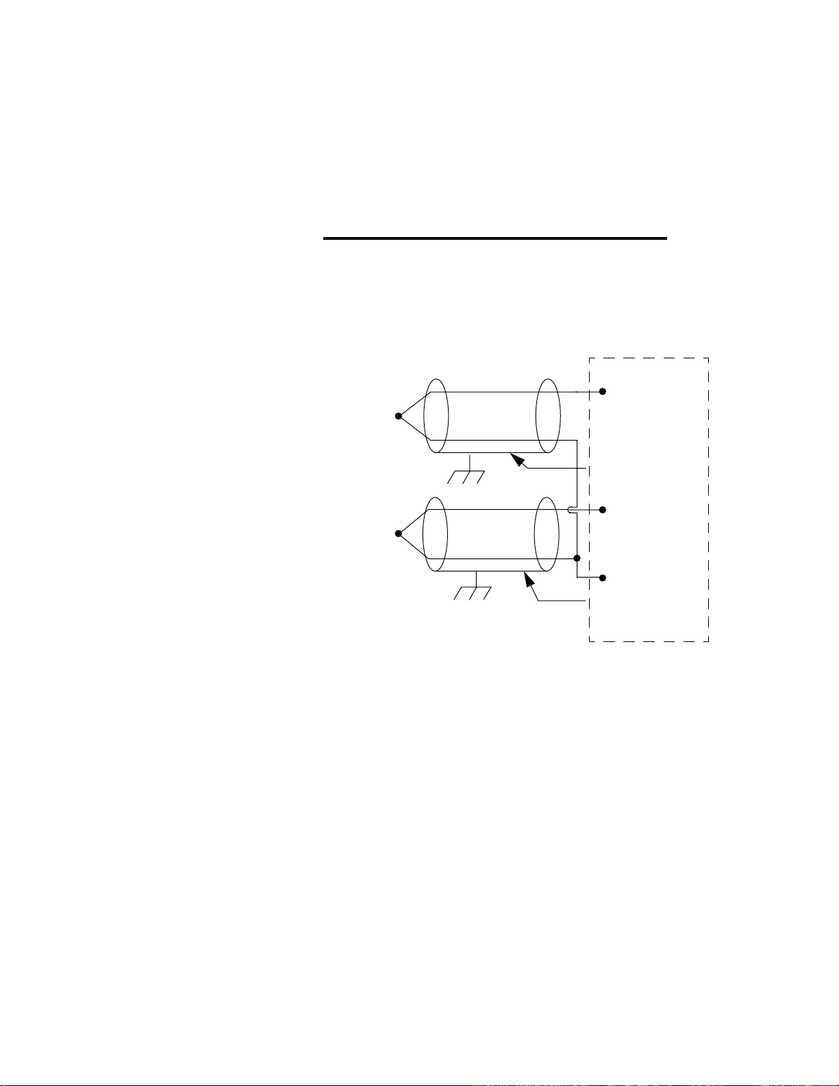
Chapter 2: Hardware Installation PPC-2000 User’s Guide
A T/C is connected to a single-ended input by wiring the
positive signal lead to the A or B terminal and the negative
signal lead to the analog COM terminal. See Figure 2.32 and
refer to Table 2.13 on page 48.
∫
WARNING!
Thermocouples connected to single-ended inputs
(PPC-2022) must be isolated (ungrounded) and
should not be embedded within heater elements as
some cartridge heaters are constructed.
.
AITB
1A (input 1+)
shield
(if present)
2A (input 2+)
Analog COM
frame ground
shield
(if present)
Figure 2.32 Thermocouples Connected to
Single-ended Inputs 1 and 2
Connecting RTDs
Two-wire RTDs are connected between the A and B terminals
of the selected input. They may only be used with a differential
analog input module. A jumper wire must be added on the
terminal board from the B terminal to the COM terminal. See
Figure 2.33 on page 51.
50 Watlow Anafaze Doc.# 30002-00 Rev 2.3
Page 75

PPC-2000 User’s Guide Chapter 2: Hardware Installation
A
B
COM
AITB
1A (input 1+)
1B (input 1-)
2A (input 2+)
2B (input 2-)
COM
Figure 2.33 Wiring 2-Wire RTDs: Input 1 and 2
Shown
Three-wire RTDs may only be used with differential analog
input modules. The single wire side of a 3-wire RTD sensor
connects to the COM terminal, one of the double wire sides
connects to the A terminal and the other connects to the B
terminal. Both A and B terminals must be of the same desired
input, i.e., 1A and 1B. See Figure 2.34.
AITB
1A (input 1+)
1B (input 1-)
2A (input 2+)
2B (input 2-)
COM
Figure 2.34 Wiring 3-Wire RTDs: Input 1 and 2
Shown
Doc.# 30002-00 Rev 2.3 Watlow Anafaze 51
Page 76
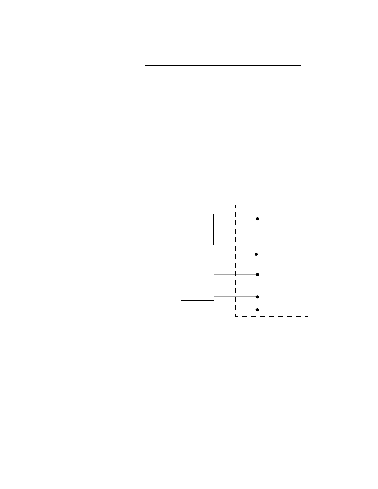
Chapter 2: Hardware Installation PPC-2000 User’s Guide
ç
CAUTION!
Do not connect the COM terminals on the AITB to
earth ground. Connecting COM to earth ground limits
the input protection to ±10Vac and could result in
damage to the input circuit.
Connecting Sensors with Linear Voltage Signals
For sensors with single output connections, connect the
negative input (B terminal) to the sensor common terminal.
Differential voltage transducers or sensors, such as bridges,
should be connected with the positive signal lead on the A
terminal and the negative signal lead to the B terminal for the
selected input. See Figure 2.35.
Check sensor power supply connections and ground
connections to avoid exceeding the common mode range of the
Analog Input module or creating ground loops.
+
Transducer
with linear
voltage
output
COM
AITB
1A (input 1+)
1B (input 1-)
Transducer
with linear
voltage
output
+
-
2A (input 2+)
2B (input 2-)
COM
Figure 2.35 Connecting Linear Voltage Signals to
Differential Inputs 1 and 2
Single-ended voltage sources should have the positive lead on
the positive terminal of the desired input. The negative lead
should be connected to the COM terminal. See Figure 2.36 on
page 53.
52 Watlow Anafaze Doc.# 30002-00 Rev 2.3
Page 77
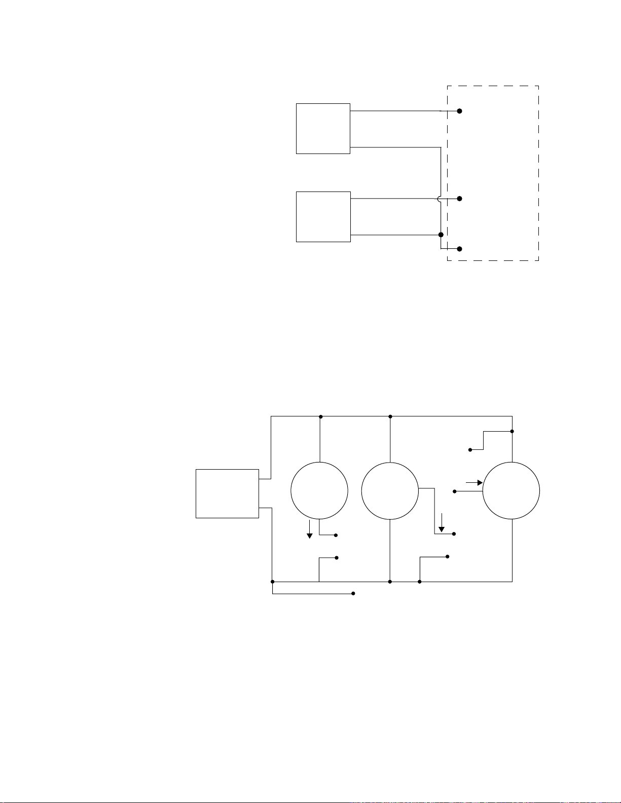
PPC-2000 User’s Guide Chapter 2: Hardware Installation
AITB
+
Transducer
1A (input 1+)
with linear
voltage
output
-
Transducer
+
with linear
voltage
output
-
Figure 2.36 Connecting Linear Voltage Signals to
Single-ended Inputs 1 and 2
Connecting Sensors with Linear Current Signals
Differential current transducers or sensors should be
connected with the positive signal lead on the A terminal and
the negative signal lead to the B terminal for the selected
input. See Figure 2.37.
Power
Supply
+ power
28V Max
+
–
Typical
2-wire
current
transmitter
–
I
1A(Input 1+)
+ power
28V Max
Typical
3-wire
current
source
transmitter
– power
out
3B(Input 3-)
I
2A (input 2+)
A COM
10 V Max
3A(Input 3+)
Typical
I
3-wire
current
sinking
transmitter
2A(Input 2+)
+ power
1B(Input 1-)
Analog Com (optional)
2B(Input 2-)
Figure 2.37 Connecting Current Inputs to a
Differential Input Module:
Input 1, 2, and 3 Shown
Single-ended current sources should be have the positive lead
on the positive terminal of the desired input. The negative lead
should be connected to the COM terminal. See Figure 2.38 on
page 54.
Doc.# 30002-00 Rev 2.3 Watlow Anafaze 53
Page 78
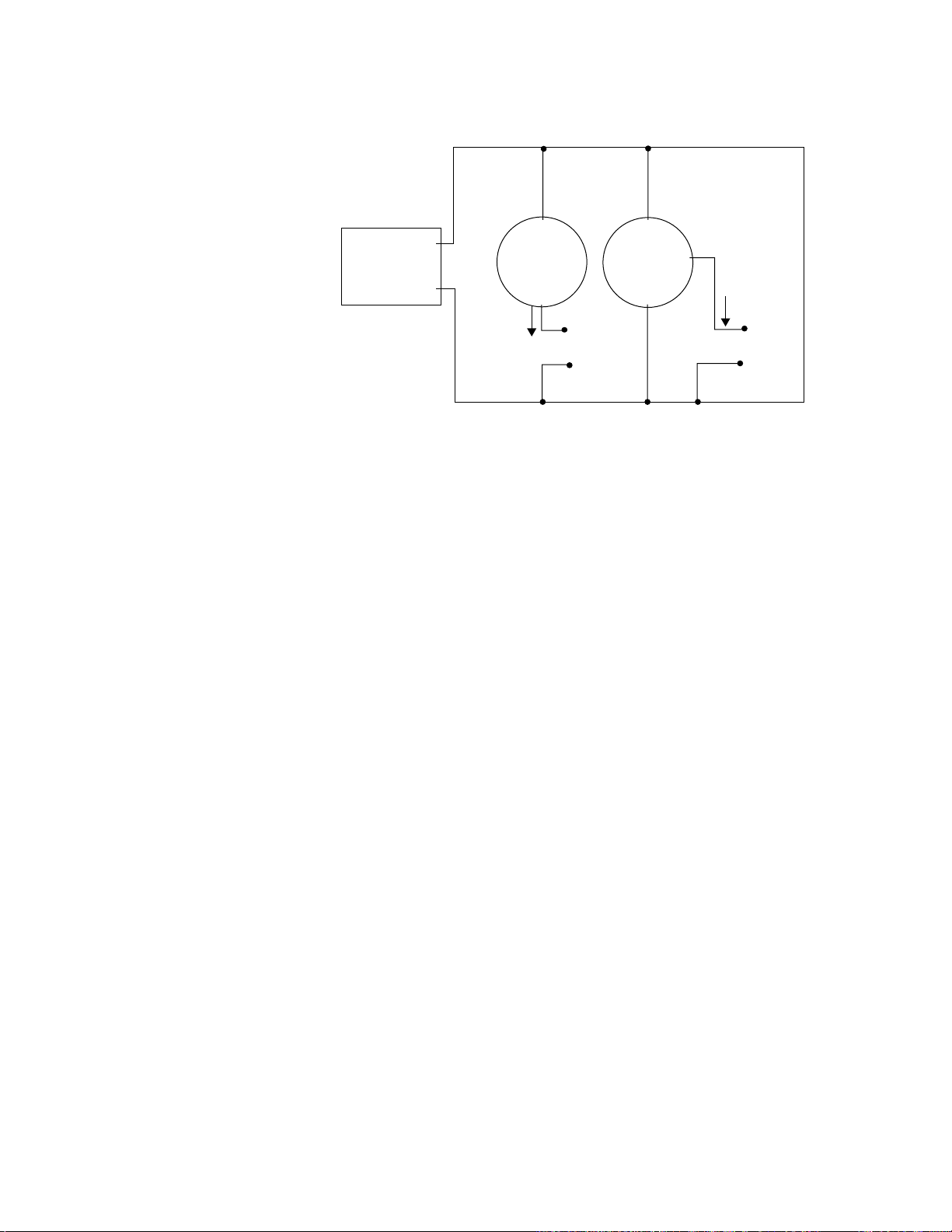
Chapter 2: Hardware Installation PPC-2000 User’s Guide
{Redraw like other I/O diagrams.}
Power
Supply
+ power
28V Max
+
–
Typical
2-wire
current
transmitter
–
I
1A(Input 1+)
Com
+ power
28 V Max
Typical
3-wire
current
source
transmitter
–
I
2A(Input 2+)
Com
Figure 2.38 Connecting Current Inputs to a
Single-ended Analog Input
Module: Input 1 and 2 Shown
54 Watlow Anafaze Doc.# 30002-00 Rev 2.3
Page 79
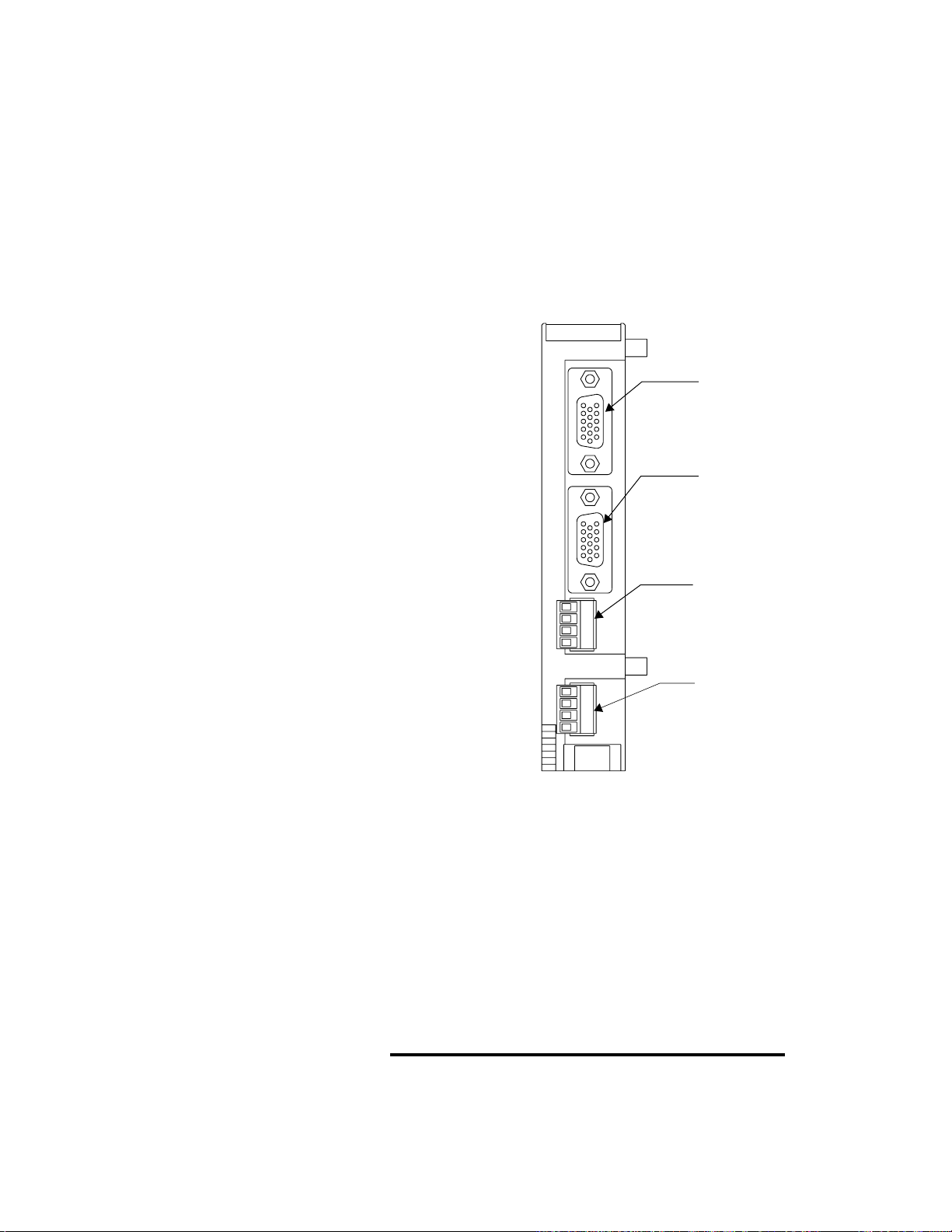
PPC-2000 User’s Guide Chapter 2: Hardware Installation
Connecting Encoders and Analog Outputs to
the PPC-2030
The PPC-2030 accepts four encoder inputs and outputs four
current or voltage signals. Encoder signals are connected to the
module via two HD-15 cables. These cables may be used in
conjunction with up to two EITBs or may be connected directly
from the encoders to the module.
Connect analog outputs via the analog output terminal block as
shown in Figure 2.39.
J4 Encoder
J4 J3 J2 J1
Input
connector
inputs 3 & 4
(HD-15 female)
J3 Encoder
Input
connectors
inputs 1 & 2
(HD-15 female)
J2 Analog
4-
4+
3-
3+
2-
2+
1-
1+
Output Terminal
Block
outputs 3 & 4
J1 Analog
Output Terminal
Block
outputs 1 & 2
Figure 2.39 PPC-2030 Connections (Bottom View)
Connecting the Encoder Input Cable to the PPC-2030
Connect the 15-pin, HD cable(s) between J1 or J2 on the PPC2030 shown in Figure 2.39 and the encoder input terminal
block (EITB).
Figure 2.40 on page 56 illustrates the EITB. Table 2.15 on page
56 shows the EITB pinout and Table 2.18 on page 59 shows the
HD D-type connector pinout. Analog Output Connections on
page 60 discusses analog outputs from the PPC-2030.
NOTE!
If more than one EITB has been installed, it may be
useful to label both ends of the HD-15 connector and
each EITB with the corresponding module address
and jack number.
Doc.# 30002-00 Rev 2.3 Watlow Anafaze 55
Page 80

Chapter 2: Hardware Installation PPC-2000 User’s Guide
EITB Connections
Table 2.15 and Table 2.16 indicate the encoder connections to
the EITB connected to the Encoder In Analog Out module.
Table 2.17 on page 57 lists the terminals that carry power.
pin 1
J2
pin 12
Figure 2.40 PPC-EITB-1
Table 2.15 Encoder Connections to the EITB
Connected to J3 on the PPC-2030
Module
I/O Number
Count 1
Frequency 1
Count 2
Frequency 2
EITB Terminal AnaWin3 Name
Phase 1 Phase 2
+-+-
2345
8 9 10 11
PPC1:EIAO 11.1.1 C
PPC1:EIAO 11.2.1 F
PPC1:EIAO 11.1.2 C
PPC1:EIAO 11.2.2 F
(Input
Spreadsheet)
1
Table 2.16 Encoder Connections to the EITB
Connected to J4 on the PPC-2030
Module
I/O Number
Count 3
Frequency 3
Count 4
Frequency 4
1.
The AnaWin3 name is shown for the Encoder In Analog Out module with address
11 on the first PPC-2000 in the system. See Inputs on page 127 for a full
explanation of Analog input naming. Both count and frequency are measured for
each input.
EITB Terminal AnaWin3 Name
Phase 1 Phase 2
+-+-
2345
8 9 10 11
PPC1:EIAO 11.1.3 C
PPC1:EIAO 11.2.3 F
PPC1:EIAO 11.1.4 C
PPC1:EIAO 11.2.4 F
(Input
Spreadsheet)
1
56 Watlow Anafaze Doc.# 30002-00 Rev 2.3
Page 81

PPC-2000 User’s Guide Chapter 2: Hardware Installation
Table 2.17 Power Connections on EITB
Voltage EITB Terminals
+5Vdc 1, 7
COM 6, 12
Encoder Wiring
The EITB accommodates four configurations of frequency/
counter inputs:
• Single-ended/single phase
• Single-ended/quadrature
• Differential/single phase
• Differential/quadrature
Note that these are four unique inputs and each input has two
phases. Both phases are used only in quadrature mode
nominally.
EITB
+
S1
-
+
S2
-
2 (input 1 phase 1+)
8 (input 2 phase 1+)
12 (COM)
Figure 2.41 EITB Single-ended Single Phase
Connections: Input 1 and 2 Shown
Doc.# 30002-00 Rev 2.3 Watlow Anafaze 57
Page 82

Chapter 2: Hardware Installation PPC-2000 User’s Guide
EITB
1+
2 (input 1 phase 1+)
Q1
Q2
2+
COM
1+
2+
COM
4 (input 1 phase 2+)
8 (input 2 phase 1+)
10 (input 2 phase 2+)
12 (COM)
Figure 2.42 EITB Single-ended Quadrature
Connections: Input 1 and 2 Shown
EITB
+
2 (input 1 phase 1+)
S1
S2
-
+
-
3 (input 1 phase 1-)
12 (COM)
8 (input 2 phase 1+)
9 (input 2 phase 1-)
12 (COM)
Figure 2.43 EITB Differential Single Phase
Connections: Input 1 and 2 Shown
58 Watlow Anafaze Doc.# 30002-00 Rev 2.3
Page 83

PPC-2000 User’s Guide Chapter 2: Hardware Installation
EITB
1+
2 (input 1 phase 1+)
1-
Q1
2+
2-
1+
1-
Q2
2+
2-
Figure 2.44 EITB Differential Quadrature
Connections: Input 1 and 2 Shown
Encoder Connections without the EITB
Encoders may be connected directly to the PPC-2030 module.
Table 2.17 and Table 2.19 on page 60 indicate the functional
pinout for HD-15 connectors connected to the Encoder In
Analog Out module connectors J1 and J2.
3 (input 1 phase 1-)
4 (input 1 phase 2+)
5 (input 1 phase 2-)
12 (COM)
8 (input 2 phase 1+)
9 (input 2 phase 1-)
10 (input 2 phase 2+)
11 (input 2 phase 2-)
12 (COM)
Table 2.18 HD-15 Encoder Signal Connections
Connector and Pin
Module
I/O
Number
Phase 1 Phase 2
+-+ -
Count 1
Frequency 1
Count 2
Frequency 2
Count 3
Frequency 3
Count 4
Frequency 4
1
The AnaWin3 name is shown for the Encoder In Analog Out module with address
11 on the first PPC-2000 in the system. Refer to Inputs on page 127 for a full
explanation of analog input naming. Both count and frequency are measured for
each input.
Doc.# 30002-00 Rev 2.3 Watlow Anafaze 59
J3-1 J3-2 J3-3 J3-10
J3-6 J3-7 J3-8 J3-11
J4-1 J4-2 J4-3 J4-10
J4-6 J4-7 J4-8 J4-11
Number
AnaWin3 Name
(Input Spreadsheet)
PPC1:EIAO 11.1.1 C
PPC1:EIAO 11.2.1 F
PPC1:EIAO 11.1.2 C
PPC1:EIAO 11.2.2 F
PPC1:EIAO 11.1.3 C
PPC1:EIAO 11.2.3 F
PPC1:EIAO 11.1.4 C
PPC1:EIAO 11.2.4 F
1
Page 84

Chapter 2: Hardware Installation PPC-2000 User’s Guide
Table 2.19 HD-15 Power Connections
Voltage Pin Number
+5Vdc 12, 15
COM 13, 14
Analog Output Connections
The connector pinouts are shown in Table 2.20. Use 16-28 AWG
wire. When making connections, tighten to 0.5 to 0.6 Nm, or 4.5
to 5.4 inch-pound.
4-
J2 J1
4+
33+
22+
11+
Outputs 3 & 4
Outputs 1 & 2
DIN Rail Latch
Figure 2.45 PPC-2030 Analog Out Terminal Block
Table 2.20 Analog Output Connections on
Encoder In Analog Out Module
Encoder In Analog
Module I/O
Number
Out Module
Connections
+-
Analog Out 1 J1-1+ J1-1- PPC1:EIAO 11.3.1
Analog Out 2 J1-2+ J1-2- PPC1:EIAO 11.3.2
Analog Out 3 J2-3+ J2-3- PPC1:EIAO 11.3.3
Analog Out 4 J2-4+ J2-4- PPC1:EIAO 11.3.4
1
The AnaWin3 name is shown for the Encoder In Analog Out module with address
11 on the first PPC-2000 in the system. Refer to Outputs on page 135 for a full
explanation of Analog output naming.
AnaWin3 Name
(Input Spread-
sheet)
1
60 Watlow Anafaze Doc.# 30002-00 Rev 2.3
Page 85
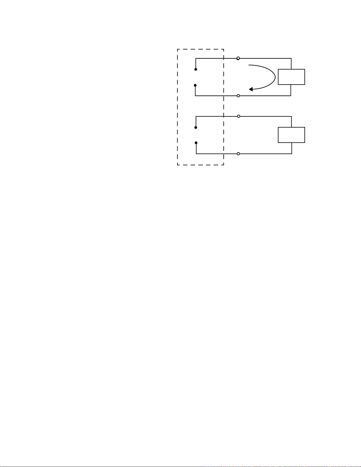
PPC-2000 User’s Guide Chapter 2: Hardware Installation
P PC-2030
1+
+
4-20mAdc
-
+
0-10Vdc
-
Figure 2.46 Analog Output Connections on a
PPC-2030: Outputs 1 and 2 Shown
Connecting I/O to the PPC-2040
A TB50 connects to a PPC-2040 Digital I/O module through the
50 pin SCSI connector. Refer to Figure 2.47 on page 62. The
terminal block interfaces to field wiring of the digital I/O
(sensors, actuators, relays, SSRs, etc.).
1-
2+
2-
+
Load
I
-
+
Load
-
Connecting the TB50 to the PPC-2040 Module
Refer to Figure 2.47 on page 62. Connect the SCSI connector
from the PPC-2040 module to the TB50.
Doc.# 30002-00 Rev 2.3 Watlow Anafaze 61
Page 86

Chapter 2: Hardware Installation PPC-2000 User’s Guide
50-pin SCSI
Connector
NOTE!
TB50
pin 1
PPC-2040
Bottom View
Figure 2.47 PPC-2040 Connection to TB50
To avoid confusing the SCSI cables during servicing,
label each end of each cable and each terminal board
with the address of the module to which it should be
connected.
TB50 Connections
Connect digital inputs and digital outputs for control signals,
alarms, and digital field I/O to the TB50. The PPC-2040 Digital
I/O Module supports up to 32 digital inputs and outputs and up
to two single-ended counter/frequency inputs. Counter inputs
may be single-phase or quadrature. Connecting one singlephase counter or frequency signal uses one digital input.
Connecting one quadrature input requires two digital inputs.
Table 2.21 on page 63 shows the TB50 pinout when used with
the PPC-2040.
Use 14 to 22 AWG wire. When making connections, tighten to
0.5 to 0.6 Nm, or 4.5 to 5.4 inch-pound.
62 Watlow Anafaze Doc.# 30002-00 Rev 2.3
Page 87

PPC-2000 User’s Guide Chapter 2: Hardware Installation
Table 2.21 Digital I/O Module Connections
Module I/O Number
Digital In/Out 1
Counter 1 Phase 1
Frequency 1
Digital In/Out 2
Counter 1 Phase 2
Digital In/Out 3
Counter 2 Phase 1
Frequency 2
Digital In/Out 4
Counter 2 Phase 2
Digital In/Out 5 5 PPC1:DIO 21.0.5
Digital In/Out 6 6 PPC1:DIO 21.0.6
Digital In/Out 7 7 PPC1:DIO 21.0.7
Digital In/Out 8 8 PPC1:DIO 21.0.8
Digital In/Out 9 9 PPC1:DIO 21.0.9
Digital In/Out 10 10 PPC1:DIO 21.0.10
Digital In/Out 11 11 PPC1:DIO 21.0.11
Digital In/Out 12 12 PPC1:DIO 21.0.12
Digital In/Out 13 13 PPC1:DIO 21.0.13
Digital In/Out 14 14 PPC1:DIO 21.0.14
Digital In/Out 15 15 PPC1:DIO 21.0.15
Digital In/Out 16 16 PPC1:DIO 21.0.16
Digital In/Out 17 17 PPC1:DIO 21.0.17
Digital In/Out 18 18 PPC1:DIO 21.0.18
Digital In/Out 19 19 PPC1:DIO 21.0.19
Digital In/Out 20 20 PPC1:DIO 21.0.20
Digital In/Out 21 21 PPC1:DIO 21.0.21
Digital In/Out 22 22 PPC1:DIO 21.0.22
Digital In/Out 23 23 PPC1:DIO 21.0.23
Digital In/Out 24 24 PPC1:DIO 21.0.24
Digital In/Out 25 25 PPC1:DIO 21.0.25
Digital In/Out 26 26 PPC1:DIO 21.0.26
Digital In/Out 27 27 PPC1:DIO 21.0.27
Digital In/Out 28 28 PPC1:DIO 21.0.28
Digital In/Out 29 29 PPC1:DIO 21.0.29
Digital In/Out 30 30 PPC1:DIO 21.0.30
Digital In/Out 31 31 PPC1:DIO 21.0.31
Digital In/Out 32 32 PPC1:DIO 21.0.32
Com (DC Common for
Input Return)
TB-50
Terminal
1
2
3
4
37 to 50 N/A
AnaWin3 Name
(Dig I/O Spreadsheet)
PPC1:DIO 21.0.1
PPC1:DIO 21.1.1 C
PPC1:DIO 21.2.1 F
PPC1:DIO 21.0.2
PPC1:DIO 21.1.1 C
PPC1:DIO 21.0.3
PPC1:DIO21.1.2 C
PPC1:DIO21.2.2 F
PPC1:DIO 21.0.4
PPC1:DIO21.1.2 C
1
2
1.
The AnaWin3 name is shown for the first Digital I/O module on the PPC-2000
system. See Digital I/O on page 132 for a complete explanation of digital I/O
names.
2.
Both count and frequency are measured for the pulse input. See Inputs on page
127 for an explanation of analog input names.
Doc.# 30002-00 Rev 2.3 Watlow Anafaze 63
Page 88
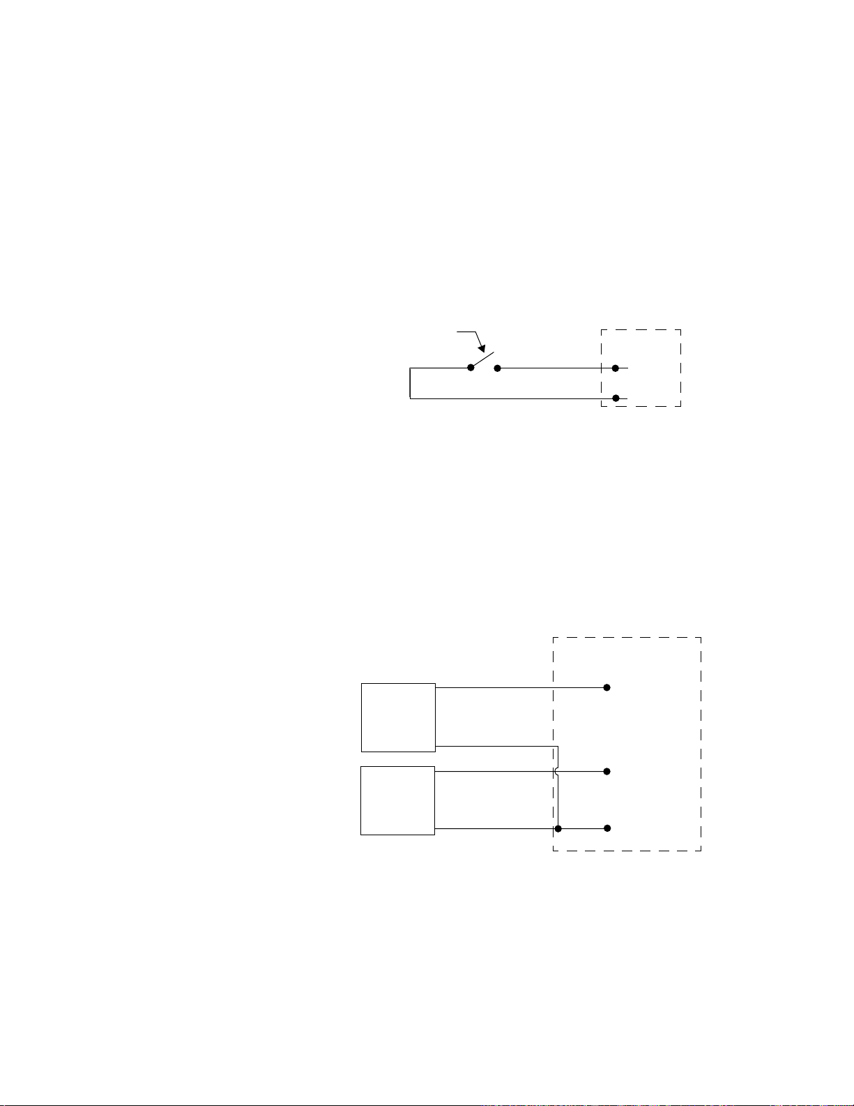
Chapter 2: Hardware Installation PPC-2000 User’s Guide
Connecting Digital Inputs
The PPC-2040 module can accept digital inputs. When the
resistance of an input device is 27 kOhm or greater, the input
is considered off by the PPC-2000. When the resistance is 1
kOhm or less, the input is considered on.
To install a switch as a digital input, connect one lead to the DC
Common input return on the TB50. Connect the other lead to
the desired digital input on the TB50. Refer to Table 2.21 on
page 63 for screw terminal numbering.
Use the Digital I/O parameters to configure digital inputs.
Refer to Digital I/O on page 132.
Digital
Input
Device
Digital In
Com
Figure 2.48 Wiring Digital Inputs
TB50
Connecting Counter or Frequency Inputs
A PPC-2040 module accepts single-phase or quadrature pulse
signals from devices such as encoders. Counts and frequencies
of the inputs may be scaled with user selectable parameters.
See Setting up User Selectable Linear Inputs on page 98 for
more information.
The PPC-2040 module can accommodate encoder signals up to
24Vdc. The following figures illustrate connecting encoders:
+
S1
-
+
S2
-
Figure 2.49 Single Phase Connections: Input 1
and 2 Shown
TB50
1 (input 1 phase 1+)
3 (input 2 phase 1+)
37 (COM)
64 Watlow Anafaze Doc.# 30002-00 Rev 2.3
Page 89

PPC-2000 User’s Guide Chapter 2: Hardware Installation
TB50
Q1
Q2
Figure 2.50 Quadrature Connections:
Connecting Digital Outputs
The digital outputs sink current from a load connected to the
controller’s power supply, or another power supply referenced
to the PPC-2000 power common. Do not exceed +24 volts.
If you must tie the external load to ground, or if you cannot
connect it as shown in Figure 2.51 through Figure 2.53, use a
solid state relay to drive your load.
The outputs conduct current when they are LOW or ON. The
maximum current sink capability is 150mA at 24Vdc. They
cannot ‘source’ current to a load.
1+
2+
COM
1+
2+
COM
1 (input 1 phase 1+)
2 (input 1 phase 2+)
3 (input 2 phase 1+)
4 (input 2 phase 2+)
Inputs 1 and 2 Shown.
37 (COM)
+ 12-24
PS
+ 5
-
PPC TB50
Digital
Out
SSR
Figure 2.51 Powering Output with 5Vdc from
PPC Supply
Doc.# 30002-00 Rev 2.3 Watlow Anafaze 65
Page 90

Chapter 2: Hardware Installation PPC-2000 User’s Guide
+
PS
-
PPC TB50
Digital
Out
SSR
Figure 2.52 Powering Output with 12-24Vdc from
PPC supply
PS
for
controller
PS
for
Output
+
-
+5 to 24Vdc
-
PPC TB50
Digital
Out
SSR
Figure 2.53 Powering Output with Separate Power
Supplies
66 Watlow Anafaze Doc.# 30002-00 Rev 2.3
Page 91
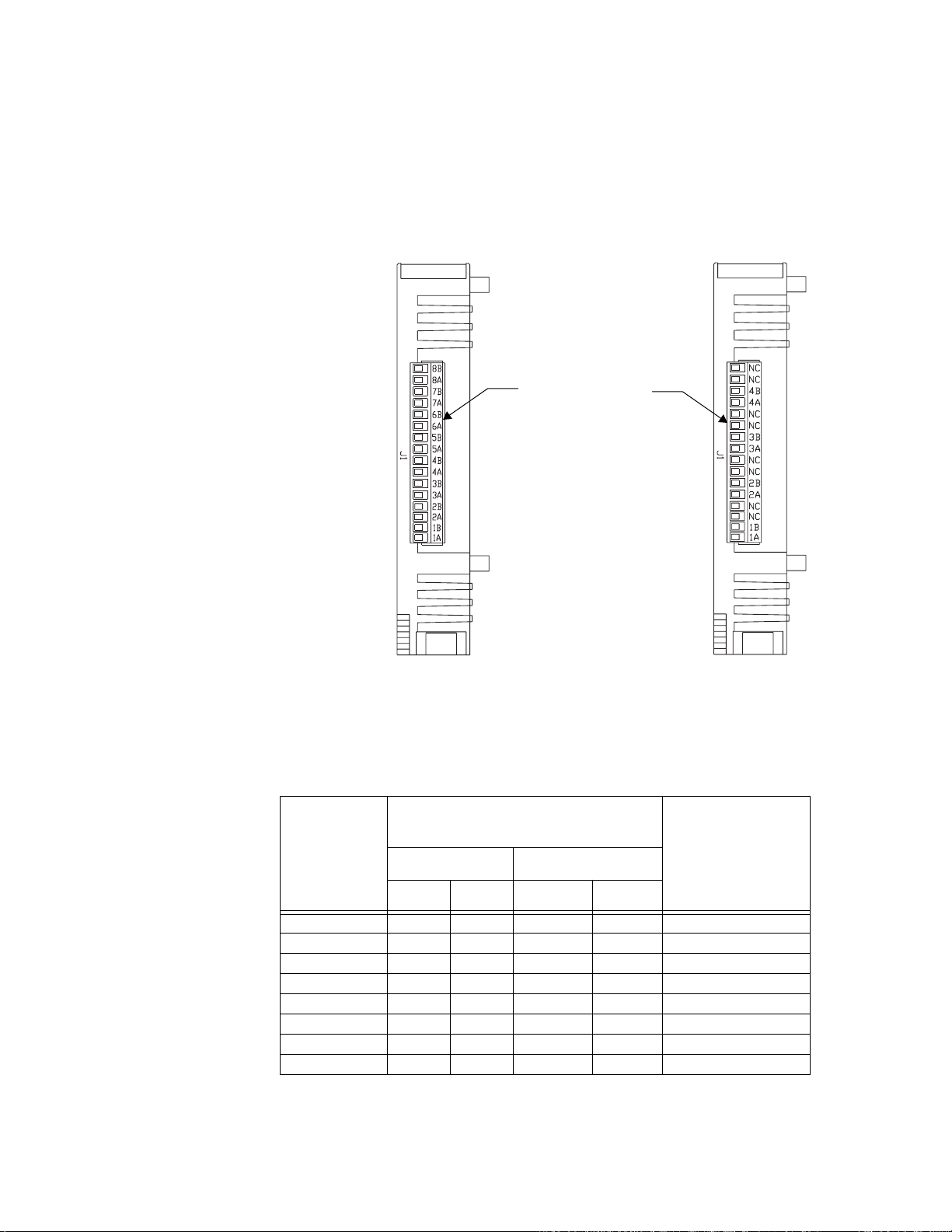
PPC-2000 User’s Guide Chapter 2: Hardware Installation
Connecting Analog Outputs to the PPC-205x
Connect wires directly to the terminals on the bottom of the
PPC-205x modules. The PPC-2050 can source up to eight
analog signals and the PPC-2051 up to four.
Table 2.22 lists the terminal connections for the PPC-2050
module.
16-pin Terminal Block
for Analog Outputs
PPC-2050 PPC-2051
Figure 2.54 PPC-205x Connections (Bottom View)
Table 2.22 Analog Output Connections on
Analog Out Module
Analog Out Module
Module I/O
Connections
Number
Voltage Current
+ - Source Sink
Analog Out 1 1A 1B 1B 1A PPC1:AO 31.1
Analog Out 2 2A 2B 2B 2A PPC1:AO 31.2
Analog Out 3 3A 3B 3B 3A PPC1:AO 31.3
Analog Out 4 4A 4B 4B 4A PPC1:AO 31.4
Analog Out 5 5A 5B 5B 5A PPC1:AO 31.5
Analog Out 6 6A 6B 6B 6A PPC1:AO 31.6
Analog Out 7 7A 7B 7B 7A PPC1:AO 31.7
Analog Out 8 8A 8B 8B 8A PPC1:AO 31.8
1.
The AnaWin3 name is shown for the Encoder In Analog Out module with address
11 on the first PPC-2000 in the system. Refer to Outputs on page 135 for a full
explanation of Analog output naming.
AnaWin3 Name
(Input
Spreadsheet)
1
Doc.# 30002-00 Rev 2.3 Watlow Anafaze 67
Page 92
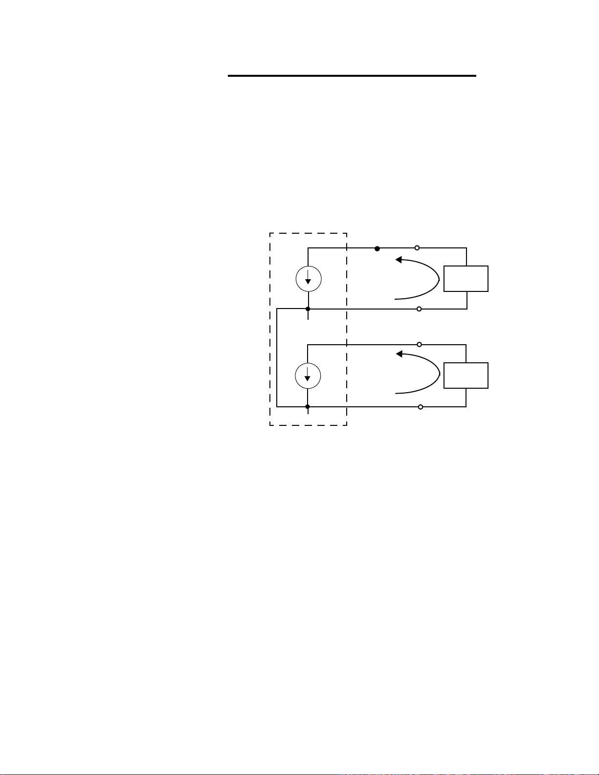
Chapter 2: Hardware Installation PPC-2000 User’s Guide
NOTE!
On the PPC-2050, each consecutive pair of analog
outputs—1-2, 3-4, 5-6 and 7-8—shares an internal
power supply. In current mode the power supply + is
shared, and in voltage mode the common is shared. If
an external power supply is tied into the internal
power supply though the B pin, the signal to each
output may be distorted. It may be necessary to use a
separate external power supply for each analog
output within the pair. Each output on the PPC-2051
has a separate internal power supply so the same
external power supply may be used.
PPC-2050
i
i
1A
1B
2A
2B
Sink
-
Load
I
+
Sink
-
I
Load
+
Source
Source
+
15V
Figure 2.55 Analog Output Connections on a
PPC-2050 Configured for Current:
Outputs 1 and 2 Shown
68 Watlow Anafaze Doc.# 30002-00 Rev 2.3
Page 93

PPC-2000 User’s Guide Chapter 2: Hardware Installation
PPC-2050
+
v
-
+
v
-
com
1A
1B
2A
2B
Load
+
Load
+
-
-
Figure 2.56 Analog Output Connections on a
PPC-2050 Configured for Voltage:
Outputs 1 and 2 shown
PPC-2051
1A
Sink
-
NOTE!
I
i
v
1B
2A
+
2B
Load
+
Source
+
Load
-
Figure 2.57 Analog Output Connections on a
PPC-2051 Configured for Current and
Voltage: Outputs 1 and 2 shown
The B terminal sources current and the A terminal
sinks it on outputs configured for current. On outputs
configured for voltage the A terminal is at the greater
potential.
Doc.# 30002-00 Rev 2.3 Watlow Anafaze 69
Page 94

Chapter 2: Hardware Installation PPC-2000 User’s Guide
Connecting to the Relay Outputs on the
PPC-206x
The PPC-2061 and PPC-2062 provide connections located on
the bottom panel for eight electromechanical relay outputs and
three counter inputs. Relay output field wiring is terminated at
a sixteen position removable terminal block.
16-pin terminal block
for relay outputs
Common Terminals
PPC-2062 PPC-2061
Figure 2.58 PPC-206x Connections
(bottom view)
70 Watlow Anafaze Doc.# 30002-00 Rev 2.3
Page 95
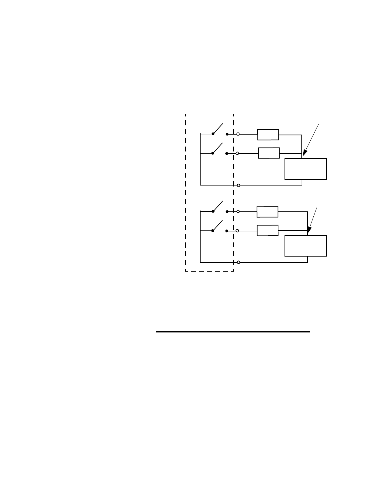
PPC-2000 User’s Guide Chapter 2: Hardware Installation
)
Wiring PPC-2061 Relay Outputs
The PPC-2061 has 16 normally open relay outputs. Outputs 1
to 8 share one common, and outputs 9-16 share the second
common. Either AC or DC may be switched. See Figure 2.59
for an example of how to connect to the relay outputs.
Table 2.23 on page 72 lists the connections to the PPC-2060 and
PPC-2061 modules.
PPC-2061
Relay 1
Relay 2
Relay 9
Relay 10
1
2
C1
9
10
C2
Load
Load
Load
Load
Neutral or 120V
L2 (AC)
AC or DC
Source
L1 (AC)
Neutral or 120V
L2 (AC
AC or DC
Source
L1 (AC)
Figure 2.59 Relay Output Connections on a PPC-
2061: Outputs 1, 2, 9 and 10 shown
∫
WARNING!
Wiring PPC-2062 Relay Outputs
Doc.# 30002-00 Rev 2.3 Watlow Anafaze 71
Do not switch AC neutral (L2). Load switching must
occur on the hot (L1) side of the AC line. Failure to do
so could cause injury or death.
The PPC-2062 has eight normally open, single-contact relay
outputs. The load may be connected to either contact. DC or AC
power may be switched. See Figure 2.60 on page 72 for an
example of how to connect to the relay outputs.
Page 96

Chapter 2: Hardware Installation PPC-2000 User’s Guide
PPC-2062
1A
Relay 1
Load
L2 (AC)
AC or DC
Source
1B
L1 (AC)
2A
Load
L2 (AC)
Relay 2
AC or DC
Source
2B
L1 (AC)
Figure 2.60 Relay Output Connections on a
PPC-2062: Outputs 1 and 2 Shown
Table 2.23 Relay Output Connections on
PPC-206x Digital Output Modules
Digital Out Module
Module
I/O Number
PPC-2061
Connections
PPC-2062
Out Com
Digital Out 1 1 C1 1A 1B PPC1:DO 41.1
Digital Out 2 2 C1 2A 2B PPC1:DO 41.2
Digital Out 3 3 C1 3A 3B PPC1:DO 41.3
Digital Out 4 4 C1 4A 4B PPC1:DO 41.4
Digital Out 5 5 C1 5A 5B PPC1:DO 41.5
Digital Out 6 6 C1 6A 6B PPC1:DO 41.6
Digital Out 7 7 C1 7A 7B PPC1:DO 41.7
Digital Out 8 8 C1 8A 8B PPC1:DO 41.8
Digital Out 9 9 C2 n/a n/a PPC1:DO 41.9
Digital Out 10 10 C2 n/a n/a PPC1:DO 41.10
Digital Out 11 11 C2 n/a n/a PPC1:DO 41.11
Digital Out 12 12 C2 n/a n/a PPC1:DO 41.12
Digital Out 13 13 C2 n/a n/a PPC1:DO 41.13
Digital Out 14 14 C2 n/a n/a PPC1:DO 41.14
Digital Out 15 15 C2 n/a n/a PPC1:DO 41.15
Digital Out 16 16 C2 n/a n/a PPC1:DO 41.16
1
The AnaWin3 name is shown for the Digital Out module with address 41 on the
first PPC-2000 in the system. See Digital I/O on page 132 for a full explanation
of Digital I/O naming.
AnaWin3 Name
(Dig I/O Spread-
sheet)
1
72 Watlow Anafaze Doc.# 30002-00 Rev 2.3
Page 97
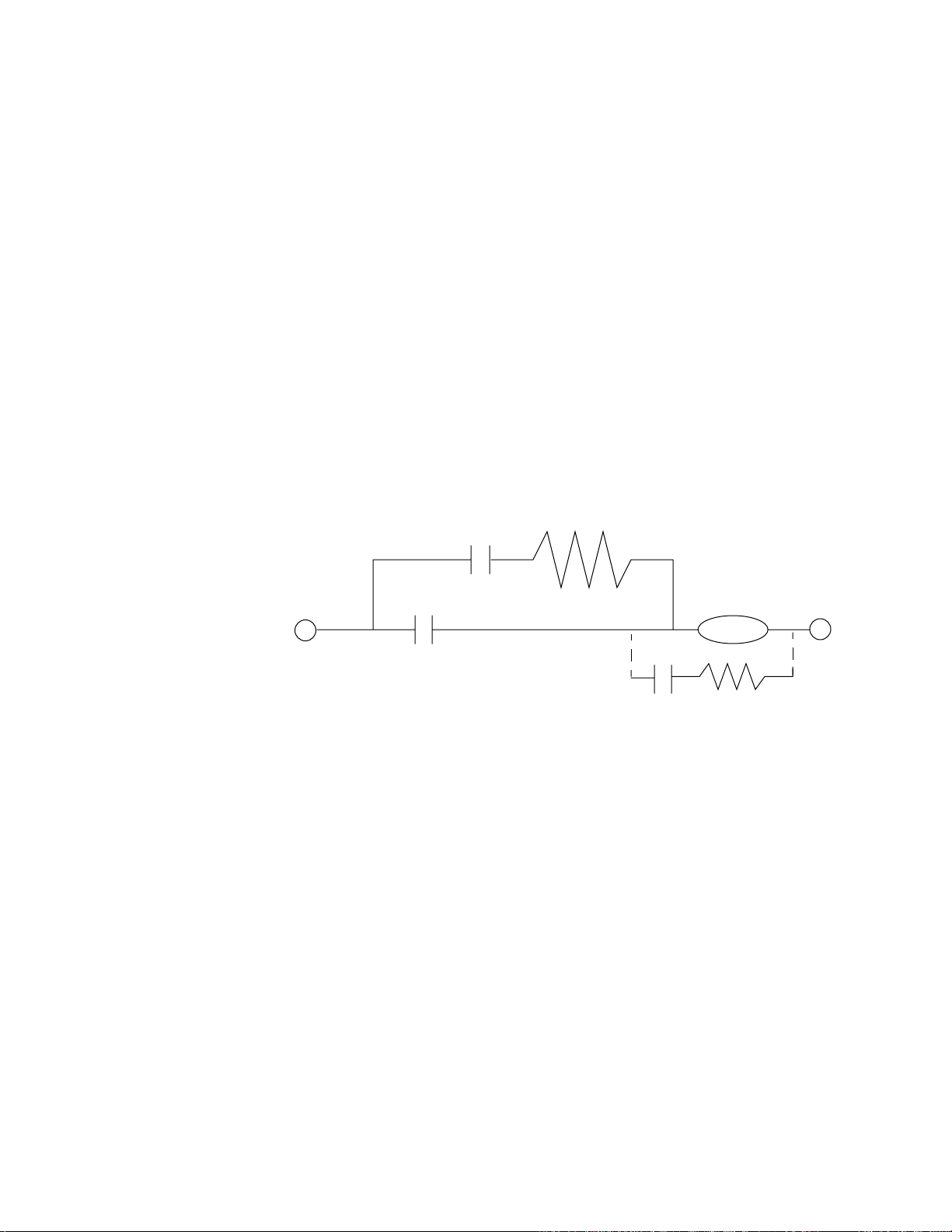
PPC-2000 User’s Guide Chapter 2: Hardware Installation
Using Snubbers for Relay Outputs
Relay contacts can arc and/or generate EMI. Over time, arcing
will shorten the life of relay contacts and EMI can disrupt
system functions. Use snubbers—a resistor and capacitor in
series— to protect against EMI and lengthen relay life.
The capacitor should be non-polarized and may be metallized
polyester film or metallized polypropylene and the voltage
rating must be 600Vdc/250Vac. The resistor may be carbon
composition or carbon film. It should be 0.5 or 1 watt with 5%
tolerance. Use 1 watt if the contacts are used in a rapid cycling
application.
The following values are acceptable for most applications using
the PPC-2061 and PPC-2062 relay output modules:
• Resistor: 120 Ω
• Capacitor: 0.47 µF
Install the snubber across the contacts or the load. Generally,
it performs more reliably across the contacts.
120/240Vac C
H
Contacts
Figure 2.61 Snubber Connections
Preferred Method
R
N
Load
Alternative Method
Doc.# 30002-00 Rev 2.3 Watlow Anafaze 73
Page 98

Chapter 2: Hardware Installation PPC-2000 User’s Guide
Connecting Digital Inputs to the PPC-207x
Connect wires directly to the terminals on the bottom of the
PPC-207x modules. Up to 16 inputs are accommodated.
Depending on the module type, DC and AC inputs are
accommodated.
Input
Connections
(2072 only)
-
DC
Source
+
Common
Connections
PPC-2070
PPC-2072
Figure 2.62 PPC-207x Connections
(bottom view)
Input Device
+
DC
Source
-
--Input Device
---
Å
---
---
---
---
PPC-2071
PPC-2073
PPC-2070/
PPC-2071
1
2
C
Figure 2.63 Input Connections to a PPC-2070 or
PPC-2072: Inputs 1 and 2 shown
74 Watlow Anafaze Doc.# 30002-00 Rev 2.3
Page 99

PPC-2000 User’s Guide Chapter 2: Hardware Installation
(PPC-2073 only)
---
---
-
DC
Source
+
(PPC-2073 only)
-
DC
Source
+
---
---
---
---
+
DC
Source
+
DC
Source
-
Figure 2.64 Input Connections to a PPC-2071 or
---
---
-
---
Input Device
---
---
---
Å
Å
Input Device
Input Device
Input Device
Input Device
PPC-2071/
PPC-2073
1
2
C1
9
10
C2
PPC-2073: Inputs 1,2, 9 and 10 Shown
PPC-2072/
PPC-2073
C/C1
+
DC
Source
-
V+
Sensor
Circuit
V-
Current Sinking Field Device
Sensor’s
Output
1
Figure 2.65 Connecting a Current Sinking Field
Device to a PPC-2072 or PPC-2073:
Input 1 Shown
Doc.# 30002-00 Rev 2.3 Watlow Anafaze 75
Page 100

Chapter 2: Hardware Installation PPC-2000 User’s Guide
PPC-2072/
PPC-2073
C/C1
V-
–
DC
Source
+
Sensor
Circuit
V+
Sensor’s
Output
1
Current Sourcing Field Device
Figure 2.66 Connecting a Current Sourcing Field
Device to a PPC-2072 or PPC-2073:
Input 1 Shown
Table 2.24 Digital Input Connections on
PPC-207x Modules
Digital In Module
Module I/O
Connections
Number
PPC-2070
PPC-2072
PPC-2071
PPC-2073
Input Com Input Com
Digital In 1 1 C 1 C1 PPC1:DI 51.1
Digital In 2 2 C 2 C1 PPC1:DI 51.2
Digital In 3 3 C 3 C1 PPC1:DI 51.3
Digital In 4 4 C 4 C1 PPC1:DI 51.4
Digital In 5 5 C 5 C1 PPC1:DI 51.5
Digital In 6 6 C 6 C1 PPC1:DI 51.6
Digital In 7 7 C 7 C1 PPC1:DI 51.7
Digital In 8 8 C 8 C1 PPC1:DI 51.8
Digital In 9 n/a n/a 9 C2 PPC1:DI 51.9
Digital In 10 n/a n/a 10 C2 PPC1:DI 51.10
Digital In 11 n/a n/a 11 C2 PPC1:DI 51.11
Digital In 12 n/a n/a 12 C2 PPC1:DI 51.12
Digital In 13 n/a n/a 13 C2 PPC1:DI 51.13
Digital In 14 n/a n/a 14 C2 PPC1:DI 51.14
Digital In 15 n/a n/a 15 C2 PPC1:DI 51.15
Digital In 16 n/a n/a 16 C2 PPC1:DI 51.16
1
The AnaWin3 name is shown for the Digital In module with address 51 on the first
PPC-2000 in the system. See Digital I/O on page 132 for a full explanation of
digital I/O output naming.
AnaWin3
Name (Dig I/O
Spreadsheet)
1
76 Watlow Anafaze Doc.# 30002-00 Rev 2.3
 Loading...