

Page 1
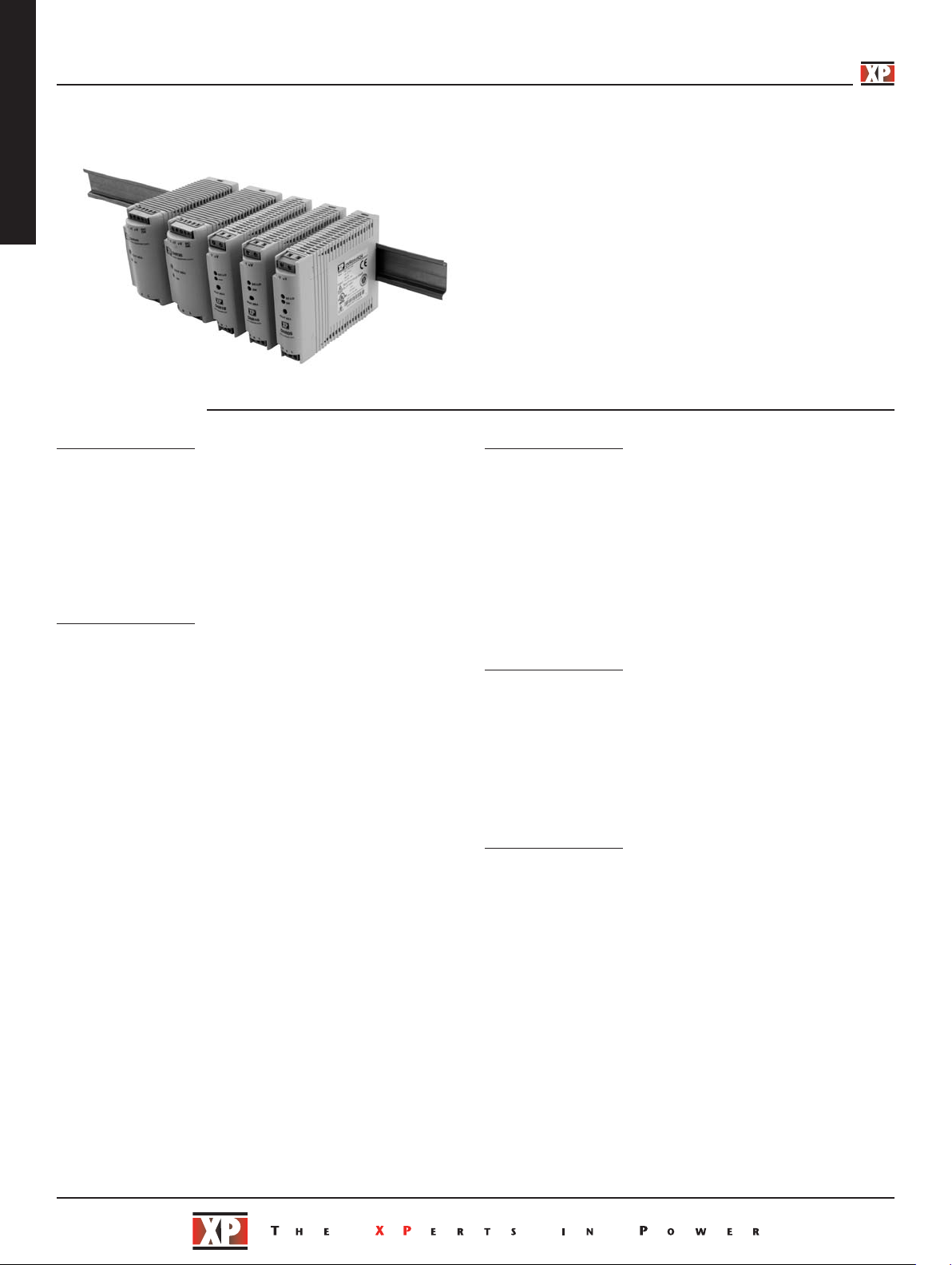
5-60 Watts
DNR05-60 Series
ppower.com
x
AC-DC
Specification
Input
Input Voltage • 90-264 VAC, 120-370 VDC: DNR05/10/18
Input Frequency • 47-63 Hz
Inrush Current • 5-18 W: 10/18 A at 115/230 VAC
Power Factor • Meets EN61000-3-2 for class A equipment
Earth Leakage Current • 0.8 mA max
Output
Output Voltage • See tables
Output Voltage Trim • See tables
Initial Set Accuracy • ±1%
Minimum Load • No minimum load required
Start Up Delay • <1000 ms
Start Up Rise Time • <150 ms
Hold Up Time • 5 W: 30/130 ms at 115/230 VAC
Line Regulation •
Load Regulation •
Transient Response • 300 µs for a 50% load change
Ripple & Noise •
Overvoltage Protection • Output clamps at 120-145% Vnom
Overload Protection • 105-145%
otection
cuit Pr
t Cir
Shor
Temperature • ±0.03%/ºC
Coefficient
85-264 VAC, 90-375 VDC: DNR30/60
30 W: 20/40 A at 115/230 VAC
60 W: 30/60 A at 115/230 VAC
10 W: 25/100 ms at 115/230 VAC
18 W: 20/75 ms at 115/230 VAC
30 W: 20/30 ms at 115/230 VAC
60 W: 20/30 ms at 115/230 VAC
: ±1.0% max
5-18 W
30-60 W: ±0.5% max
±2.0% max
:
5-18 W
30-60 W: ±0.5% max
50 mV pk-pk, 20 MHz BW
t (Hiccup mode)
rip and r
: T
5-18 W
•
30-60 W: Constant power
estar
• Rugged Design for Industrial Applications
• Up to 89% Efficiency
• Wide Adjustment Range
• DC OK 24 V Models
• DC Standby Versions
• Connector Options
• Full Power to +60 ˚C
General
ficiency
Ef
Isolation • 3000 VAC Input to Output
Switching Frequency • 100 KHz typical
Signals • DC ON indicator LED Green: All models
MTBF • 200 kHrs typical per MIL-HDBK-217F
See tables
•
1500 VAC Input to Ground
500 VAC Output to Ground
DC LOW indicator LED Red:
5-18 W models
DC OK: 24 V 30-60 W models
GF, +40 ºC
Environmental
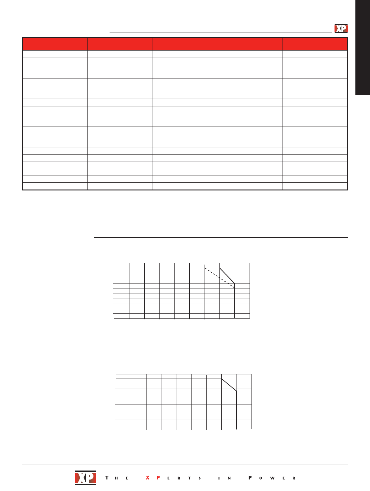
Operating Temperature • -10 °C to +70 °C, derate linearly from
Cooling • Convection-cooled
Operating Humidity • 20-95% RH, non-condensing
Storage Temperature • -25 ºC to +85 ºC
Shock • 4 g, 22 ms, X, Y & Z axis
Vibration • 1 g, 10 Hz to 500 kHz, along X, Y & Z axis
+50 °C for 5 & 18 W models, +60 °C for
all other models (See derating curves)
EMC & Safety
Emissions •
ents
monic Cur
Har
Voltage Flicker • EN61000-3-3 amendments 1 & 2
ESD Immunity • EN61000-4-2, level 3 Perf Criteria A
Radiated Immunity • EN61000-4-3, level 3 Perf Criteria A
EFT/Burst • EN61000-4-4, level 3 Perf Criteria A
ge
Sur
Dips & Inter
Safety Approvals • EN60950-1:2001, UL508,
r
ruptions
EN55022, level B conducted
EN61000-3-2, class A
•
EN61000-4-5, level 3 Per
•
EN61000-4-11, 30% 10 ms,
•
60% 100 ms, 100% 5000 ms
f Criteria A, B, B
Per
UL1310 - see note 3 & ratings table,
UL60950-1, cUL60950-1, CE Mark
f Criteria A
Page 2
Models and Ratings
-10 0 10
20 30
40
50
60
70
20
40
60
80
100
0
Ambient Temp (˚C)
Load (%)
-10 0 10
2
20
40
60
80
100
0
Load (%)
DNR 05, 10, 18
DNR05
DNR18
DNR10
-10 0 10
20 30
40
50
60
70
20
40
60
80
100
0
Ambient Temp (˚C)
Load (%)
DNR 30, 60, 120, 240
Output
Voltage
5 V 4.50-5.75 V 1.000 A 69% DNR05US05
12 V 10.80-13.80 V 0.420 A 72% DNR05US12
15 V 13.50-17.25 V 0.340 A 72% DNR05US15
24 V 21.60-28.80 V 0.210 A 72% DNR05US24
5 V 4.50-5.75 V 2.000 A 73% DNR10US05
12 V 10.80-13.80 V 0.840 A 75% DNR10US12
15 V 13.50-17.25 V 0.670 A 76% DNR10US15
24 V 21.60-28.80 V 0.420 A 76% DNR10US24
5 V 4.50-5.75 V 3.000 A 75% DNR18US05
12 V 10.80-13.80 V 1.500 A 77% DNR18US12
15 V 13.50-17.25 V 1.200 A 77% DNR18US15
24 V 21.60-28.80 V 0.750 A 77% DNR18US24
5 V 5.00-5.50 V 6.000 A 79% DNR30US05
12 V 12.00-14.00 V 2.500 A 84% DNR30US12
24 V 24.00-28.00 V 1.250 A 86% DNR30US24
48 V 48.00-55.00 V 0.625 A 86% DNR30US48
5 V 5.00-5.50 V 10.000 A 79% DNR60US05
12 V 12.00-14.00 V 5.000 A 86% DNR60US12†
24 V 24.00-28.00 V 2.500 A 89% DNR60US24†
48 V 48.00-55.00 V 1.250 A 89% DNR60US48†
Notes
1. Add suffix ‘-S’ for spring clamp option.
2. 30-60 W models are
3. Approved to UL1310.
† Available from Farnell. See pages 204-206.
suitable for battery-charging applications.
Output
Voltage Trim
Current
Typical
Efficiency
DNR05-60
Model
Number
(1,3)
(1,3)
(1,3)
(1,3)
(1,3)
(1,3)
(1,3)
(1,3)
(1,3)
1,3)
(
(1,3)
(1,3)
(1)
(1,3)
(1,3)
(1,3)
(1)
AC-DC
(1)
(1,3)
(1,3)
Derating Curves
DNR5-18 Models
DNR30-60 Models
Page 3

5
4.53 (115.0)
1.59
(40.5)
3.60
(90.0)
AC Input
DC Output
ON
123
1
2
3
4
M
4.53 (115.0)
0.89
(
22.5)
1
2
3.48
(88.5)
1 2 3
DC Output
DC LO
ON
AC Input
echanical Details
5/10/18 W Models
AC-DC
DNR05-60
Notes
1. All dimensions in inches (mm).
2. Weight 0.33 lb (150 g) approx.
30/60 W Models
DNR05, 10, 18 Connections
Conn Pin
AC
Input
DC
Output
Designation
1 Ground
2 Neutral
3 Line
1 Positive
2 Negative
Notes
1. All dimensions in inches (mm).
eight 0.6 lb (275 g) appr
2. W
ox.
DNR30/60 Connections
Conn Pin
Input
Output
1 Gr
AC
2 Neutral
3 Line
1 DC OK*
2 Positive
DC
3 Positive
4 Negative
5 Negative
* 24 V & standby models only.
Designation
ound
Page 4

S
+
-
-
D
C OK
Relay
Control
Relay
Coil
Battery
Fuse
D1
L
OAD
DC Output
ON
123
Maximum current drain from
battery by PSU when inactive
22 mA.
+
1
2
3
4
5
DCOK
DCOK
22K
0.5W
5.1K
0.3W
R
L
> 700ohm
-Vout
-Vout
DCOK
22K
0.5W
5.1K
0.3W
-Vout
tandby Versions
AC-DC
DNR05-60
DNR30/60 connection for DC standby system applications
Output Set Voltages For Standby Versions
Model Voltage Current Efficiency
DNR30US12* 13.6 V 2.20 A 84%
DNR30US24* 27.2 V 1.10 A 86%
DNR30US48* 54.5 V 0.55 A 86%
DNR60US12* 13.6 V 4.40 A 86%
DNR60US24* 27.2 V 2.20 A 89%
DNR60US48* 54.5 V 1.10 A 89%
Notes
‘*’ at the end of the part number denotes DC standby system.
DNR30/60 Connections
Conn Pin
nput
I
utput
O
1 G
C
A
2 Neutral
3 L
1 D
2 Positive
DC
3 P
4 N
5 Negative
24 V & standby models only.
*
Designation
round
ine
C OK*
ositive
egative
DC OK
30-60 W Models
Output good = 24 V
Output not good = 0 V
Example using external relay
to create volt-free contact
Standard on 24 V models, 30-60 W only.
Example using external components
eate TTL signal
to cr
09-Oct-07
 Loading...