

Page 1
ISO 9001
6
PID/Integrated Controller
User's Guide
10-40670
December, 2019
1241 Bundy Boulevard., Winona, Minnesota USA 55987
Phone: +1 (507) 454-5300, Fax: +1 (507) 452-4507
http://www.watlow.com
TOTAL
CUSTOMER
SATISFACTION
3 Year Warranty
Registered Company
Winona, Minnesota USA
Made in the U.S.A.
Page 2
Safety Information
We use note, caution and warning symbols throughout this book to draw your attention to
important operational and safety information.
• A “NOTE” marks a short message to alert you to an important detail.
• A “CAUTION” safety alert appears with information that is important for protecting your
equipment and performance. Be especially careful to read and follow all cautions that apply to your application.
• A “WARNING” safety alert appears with information that is important for protecting you,
others and equipment from damage. Pay very close attention to all warnings that apply to your application.
• The safety alert symbol, (an exclamation point in a triangle) precedes a general
CAUTION or WARNING statement.
• The electrical hazard symbol, (a lightning bolt in a triangle) precedes an electric shock hazard CAUTION or
WARNING safety statement. Further explanations follow:
Symbol Explanation
CAUTION – Warning or Hazard that needs further explanation than label on unit
can provide. Consult User's Guide for further information.
ESD Sensitive product, use proper grounding and handling techniques when
installing or servicing product.
Unit protected by double/reinforced insulation for shock hazard prevention.
Do not throw in trash, use proper recycling techniques or consult manufacturer
for proper disposal.
Enclosure made of Polycarbonate material. Use proper recycling techniques or
consult manufacturer for proper disposal.
Unit can be powered with either alternating current (ac) voltage or direct current
(dc) voltage.
®
Unit is a Listed device per Underwriters Laboratories
. It has been evaluated to
United States and Canadian requirements for Process Control Equipment.
®
61010 and CSA C22.2 No. 61010. File E185611 QUYX, QUYX7.
UL
See: www.ul.com
®
Unit is a Listed device per Underwriters Laboratories
. It has been evaluated
to United States and Canadian requirements for Hazardous Locations Class
1 Division II Groups A, B, C and D. ANSI/ISA 12.12.01-2007. File E184390
QUZW, QUZW7. See: www.ul.com
Watlow PM PLUS™ 6 • 2 •
Page 3

Unit is compliant with European Union directives. See Declaration of Conformity for
further details on Directives and Standards used for Compliance.
Unit has been reviewed and approved by Factory Mutual as a Temperature Limit
Device per FM Class 3545 standard. See: www.fmglobal.com
Unit has been reviewed and approved by CSA International for use as Temperature
Indicating-Regulating Equipment per CSA C22.2 No. 24. See: www.csa-international.
org
Unit has been reviewed and approved by ODVA for compliance with DeviceNet
communications protocol. See: www.odva.org
Unit has been reviewed and approved by ODVA for compliance with Ethernet/IP
communications protocol. See: www.odva.org
Warranty
The PM PLUS is manufactured by ISO 9001-registered processes and is backed by a three-year warranty to
the first purchaser for use, providing that the units have not been misapplied. Since Watlow has no control
over their use, and sometimes misuse, we cannot guarantee against failure. Watlow's obligations hereunder,
at Watlow's option, are limited to replacement, repair or refund of purchase price, and parts which upon
examination prove to be defective within the warranty period specified. This warranty does not apply to
damage resulting from transportation, alteration, misuse or abuse. The purchaser must use Watlow parts to
maintain all listed ratings.
Technical Assistance
If you encounter a problem with your Watlow controller, review your configuration information to verify that your
selections are consistent with your application: inputs, outputs, alarms, limits, etc. If the problem persists, you can
get technical assistance from your local Watlow representative (see back cover), by e-mailing your questions to
wintechsupport@watlow.com or by dialing +1 (507) 494-5656 between 7 a.m. and 5 p.m., Central Standard Time
(CST). Ask for an Applications Engineer. Please have the following information available when calling:
• Complete model number
• All configuration information
• User’s Guide
• Factory Page
Return Material Authorization (RMA)
1. Using the form found on watlow.com/rma, submit a request for a Return Material Authorization (RMA)
number before returning any item for repair. If you do not know why the product failed, contact an
Application Engineer. All RMA’s require:
• Ship-to address
• Bill-to address
• Contact name
Watlow PM PLUS™ 6 • 3 •
Page 4

• Phone number
• Method of return shipment
• Your P.O. number
• Detailed description of the problem
• Any special instructions
• Name and phone number of person returning the product.
2. Prior approval and an RMA number from the Customer Service Department is required when returning any
product. Make sure the RMA number is on the outside of the carton and on all paperwork returned. Ship on a
Freight Prepaid basis.
3. After we receive your return, we will examine it to verify the reason for the product failure. Unless otherwise
agreed to in writing, Watlow's standard warranty provisions, which can be located at www.watlow.com/terms,
will apply to any failed product.
4. In the event that the product is not subject to an applicable warranty, we will quote repair costs to you and
request a purchase order from you prior to proceeding with the repair work.
5. Watlow reserves the right to charge for no trouble found (NTF) returns.
Third Party License Guide
Introduction
PM PLUS incorporates certain third party software within the product. The license terms associated with
this software require we give copyright and license information and this Third Party License Terms List
("TPLTL") provides those details.
Fonts
Roboto
Copyright (C) 2008 The Android Open Source Project
Licensed under the Apache License, Version 2.0 (the "License"); you may not use this file except in compliance
with the License. You may obtain a copy of the License at
http://www.apache.org/licenses/LICENSE-2.0
Unless required by applicable law or agreed to in writing, software distributed under the License is distributed on
an "AS IS" BASIS, WITHOUT WARRANTIES or CONDITIONS OF ANY KIND, either express or implied. See the License
for the specific language governing permissions and limitations under the License.
The PM Plus product firmware contains the Roboto Font. PM Plus product firmware is Copyright (C) 2019 Watlow
Electric Controls, Inc.
This PM PLUS User’s Guide is copyrighted by Watlow Electric, Inc., © December 2019 with all rights reserved.
Watlow PM PLUS™ 6 • 4 •
Page 5

Table of Contents
Chapter 1: Overview .......................................9
Introduction ......................................................9
Standard Features and Benefits .......................................9
PM PLUS™ Operational Overview ....................................11
Inputs ......................................................11
Internal Functions .............................................11
Outputs .....................................................11
Configuration and Monitoring of Features Through Lists ...............12
Profiles .....................................................12
System Diagrams .................................................13
Chapter 2: Installation .....................................17
Installing the Device ...............................................17
Wiring Your New PM PLUS™ .......................................18
Isolation Block Diagram ............................................20
Chapter 3: User Interface ...................................38
Touch Keys ......................................................38
Home Screen ....................................................38
Default Home Screen Parameters .................................38
Active Messages on the Home Screen .................................39
Chapter 4: Operations .....................................40
Operations List ...................................................40
Default Operations Parameters/Sublists ............................40
Adding Custom Parameters to the Operations List ...................42
Chapter 5: Setup .........................................44
Default Configurations for Quick Start .................................44
Configuring Parameters .........................................44
Using Watlow Software to Configure Parameters .....................44
Setup List .......................................................45
Analog Input List ..............................................45
Digital Bus List ...............................................47
Linearization List ..............................................49
Process Value List .............................................50
Digital Input/Output List ........................................51
Limit List ....................................................52
Control Loop List ..............................................53
Watlow PM PLUS™ 6 • 5 • Table of Contents
Page 6

Output List ...................................................56
Alarm List ...................................................57
Current List ..................................................59
Timer List ...................................................59
Math List ....................................................60
Special Output Function ........................................61
Function Key .................................................62
Global List ...................................................62
Communications List ...........................................64
Changing PM PLUS™ to PM PLUS™ Express ...........................67
How to Enact PM PLUS™ Express .............................67
Revert from PM Express to Original Configuration ................68
Saving and Restoring Settings
Reset Original Factory Settings ...................................68
.......................................68
Chapter 6: Profiles .......................................69
Setting Up Global Features ..........................................69
Setting Up Profiles ...............................................69
Starting a Profile ..................................................70
Configuring the Function Key to Start and Stop a Profile ...............70
Configuring a Digital Input to Start and Stop a Profile .................70
Profile List ......................................................71
Chapter 7: Factory List .....................................74
Chapter 8: Features
Autotune ........................................................77
TRU-TUNE+
Input Features ....................................................79
Calibration Offset ..............................................79
Calibration of Analog Inputs .....................................81
Filter Time Constant ...........................................82
Sensor Backup ...............................................83
Set Minimum Set Point and Maximum Set Point .....................83
Scale High and Scale Low ......................................83
Range High and Range Low .....................................84
Remote Set Point
Ten Point Linearization .........................................85
Output Features ..................................................85
.......................................77
® .................................................78
.............................................84
Duplex
NO-ARC Relay ................................................85
Retransmitting a Process Value or Set Point. . . . . . . . . . . . . . . . . . . . . . . . . 86
Cool Output Curve .............................................87
Resetting a Tripped Limit .......................................87
Watlow PM PLUS™ 6 • 6 • Table of Contents
......................................................85
Page 7

Control Methods ..................................................88
Output Configuration ...........................................88
Auto (closed loop) and Manual (open loop) Control ...................88
On-Off Control ................................................89
Proportional and (P) Control .....................................90
Proportional and Integral (PI) Control ..............................90
Proportional, Integral and Derivative (PID) Control ....................91
Dead Band ...................................................91
Variable Time Base ............................................92
Single Set Point Ramping .......................................92
Compressor Control ...........................................93
Differential Control ............................................94
Ratio Control .................................................94
Duplex Control ................................................94
Motorized Valve Control ........................................94
Timer Function ...................................................94
Alarms .........................................................96
Process and Deviation Alarms ....................................96
Set Points ...................................................96
Hysteresis ...................................................97
Latching .....................................................97
Silencing Alarms ..............................................98
Blocking Alarms ..............................................98
Current Sensing ..................................................98
Open and Shorted Load Circuit Detection ...........................98
Open Loop Detection ...........................................99
Programming the Function Key ......................................99
Security Features .................................................99
Read Lock and Set Lock Levels ...................................99
Passwords ..................................................101
Modbus® - Using Programmable Memory Blocks .......................102
CIP Communications: DeviceNet or EtherNet/IP .........................103
CIP Implicit Assemblies ........................................103
Compact Assembly Class ...................................104
Modifying Implicit Assembly Members ........................104
PCCC - (Programmable Controller Communications Commands) ..........104
Profibus DP (Decentralized Peripherals) ..............................105
Chapter 9: Applications ...................................106
Example 1: Single Loop Control .....................................106
Example 2: Sensor Backup .........................................106
Example 3: Square Root ...........................................107
Example 4: Ratio .................................................107
Example 5: Differential ............................................108
Example 6: Wet Bulb / Dry Bulb .....................................109
Watlow PM PLUS™ 6 • 7 • Table of Contents
Page 8

Example 7: Vaisala ...............................................109
Example 8: Motorized Valve Control ..................................110
Chapter 10: Appendix ....................................112
Troubleshooting Alarms, Errors and Control Issues ......................112
Modbus® Programmable Memory Blocks .............................117
CIP Implicit Assemblies ...........................................120
Compact Class Assembly Structure ..................................122
PM PLUS™ Integrated PID Configuration Options .......................129
PM PLUS™ PID Configuration Options ...............................130
Specifications ...................................................131
Watlow PM PLUS™ 6 • 8 • Table of Contents
Page 9

Chapter 1: Overview
Introduction
Watlow’s PM PLUS™ has an intuitive interface with a smooth touch keypad for easy programming and readability. This reduces complexity at the front of the control. Using Composer or Configurator is highly desirable to program the PM. The PM PLUS™ is compatible with legacy EZ-ZONE PM controllers and connects via
Bluetooth
ordered in the Part number.
The PM PLUS™ can be ordered as a PID controller or an integrated controller with multiple functions
combined. Look for the device configuration code on the product label to confirm which functional options are
included on your device. Upon power up, you can see the firmware revision and Bluetooth
the device display and if Bluetooth
Standard Features and Benefits
Intuitive list flow
• Reduces menu structure to a list of lists for easy configuration
• Offers easy to read characters and color coding for a display visible from many angles
• Reduces setup time and increases operator efficiency
®
to our EZ-LINK™ mobile app for remote access configuration and monitoring, if Bluetooth® was
®
®
is part of the Part number.
logo, if enabled, on
Smooth touch keypad
• Eliminates contamination points on the front of the controller and creates better seal
• No mechanical components to wear out, easy to clean
Bluetooth® compatible with EZ-LINK™ mobile app
• Provides full descriptions of parameters and error codes
• Allows remote access capabilities without the use of cables or converters
• Provides the ability to configure the product and save parameter sets, except for Factory parameters and Profile
parameters.
High amperage integrated PID and limit controller
• Reduces wiring time and termination complexity compared with connecting other products
• Decreases component count and required panel space
• Increases user and equipment safety for over/under temperature conditions
• Drives 15 ampere resistive loads directly
Standard Bus Communications with Configuration Software
• Includes Watlow standard bus communications used by COMPOSER® or CONFIGURATOR® software
Serial communication capabilities
• Provides a wide range of protocol choices including Modbus® RTU, EtherNet/IP™, Modbus® TCP, PROFIBUS DP,
DeviceNet™ and J1939 CAN bus
• Supports network connectivity to a PC or PLC for remote set point adjustment
Watlow PM PLUS™ 6 • 9 • Chapter 1 Overview
Page 10

Enhanced control options
• Handles complex process problems such as ratio, differential, square-root, motorized valve control without
slidewire feedback, wet-bulb/dry-bulb, compressor control and peltier loads
• Provides batch process control
• Supports set point change during countdown 10-point linearization curve
• Improves sensor accuracy
Current monitoring
• Detects heater current flow and provides alarm upon a failed output device or heater load
• Drives output on open or shorted heater
Advanced PID control algorithm
• Offers TRU-TUNE®+ adaptive control for demanding applications
• Provides auto-tune for fast, efficient start-up
Built-in sensor compensation curves
• Includes Vaisala RH and altitude (pressure) curves
Profile capability
• Offers pre-programmed process control with ramp/soak programming with 40 total steps
Retransmit output
• Supports industry needs for recording
Factory Mutual (FM) approved over/under limit with auxiliary outputs
• Increases user and equipment safety for over/under temperature conditions
Memory for saving and restoring parameter settings
• Decreases service calls and time down
Agency approvals
• UL® listed, CSA, CE, RoHS, W.E.E.E., FM, SEMI F47-0200, Class 1, Div. 2 rating on some models
Touch-safe package
• Increases safety for installer/operator
• Complies with IP2X requirements
Programmable function key
• Enables simple, one-touch operation of user-defined, repetitive activities
Watlow PM PLUS™ 6 • 10 • Chapter 1 Overview
Page 11

PM PLUS™ Operational Overview
The PMPLUS receives Information from an input, performs an internal function as a response to that input,
then causes a resulting output. All of these - the inputs, the internal functions, and the outputs - are
configurable. A single PM PLUS™ can carry out several functions at the same time, such as PID control, checking for a limit condition, monitoring for several alarm situations, etc.
You may configure up to four profiles to automate a sequence of up to ten steps per profile, to further
customize and extend the application of the device.
Inputs
Inputs provide the information a programmed procedure can act upon. A basic example is a sensor monitoring
the temperature of a part being heated or cooled. Each analog input typically uses a thermocouple or RTD to
read the process temperature or the volts, current or resistance from various devices.
Optional digital input/output (DIO) hardware can be used as either an input or an output. Each DIO must be
configured as either an input or output. A digital input allows for a specific function to occur. The Function Key
can also be programmed to allow for a specific function to occur.
Internal Functions
A function is a user-programmed internal process that uses input signals to calculate a value and then perform
an action, i.e.:
• Compare an input value to the set point and calculate the optimal power for a heater
• Detect a failure of the primary sensing device and trip a contactor to remove power from the heating
element
• When a digital input signal changes, allows for a specific function to occur.
• Evaluate an incoming temperature to determine an alarm state (on or off)
Each internal function is associated with one source, or instance. For example, a control equipped with DIO,
can be configured to respond to one of the four alarms.
Outputs
Outputs are functions or actions configured to respond to information provided by an internal function. Some
output examples are: removal of the control voltage to a contactor; operating a heater, turning a light on or off,
unlocking a door, etc.
You can assign outputs to any input, and may assign more than one output to respond to a single instance of a
function. For example, alarm 2 could be used to trigger a light connected to output 1 and a siren connected to
DIO 5.
Watlow PM PLUS™ 6 • 11 • Chapter 1 Overview
Page 12

Configuration and Monitoring of Features Through Lists
PM PLUS™ features and parameters are structured in lists that you can access via the smooth-touch key
interface on the front panel for easy configuration and monitoring. You can also access lists remotely if you
prefer, using our EZ-LINK app or our CONFIGURATOR software.
List Description
Operations List This list is used to monitor or change runtime settings such as the high set point of the
limit, or monitor things like the time remaining in a profile step. It is also used to access
the main configuration lists referenced here.
Setup List This is used prior to operation to set up equipment related settings such as input type
and output cycle time.
Profile List If equipped with this feature you will use this list to configure up to 4 profiles with up to
ten steps each.
Factory List This list doesn't affect runtime operations. It is used to adjust hardware settings like
passwords or the appearance of the Home Screen, or to view the control part number.
Profiles
A profile is a sequence of steps. When a profile runs, the controller automatically executes its steps in sequence. The step type determines what action the controller performs. Steps can change temperatures and
other process values gradually over time, maintain temperatures and process values for specific periods, or
repeat a sequence of steps numerous times. At each step the profile can activate or deactivate outputs that
control other equipment. Also a step can have the controller wait for specific conditions before proceeding such
as, waiting for a switch closure and/or a specific process value to be detected by a sensor.
Input Events and Output Events
When a Profile step is programmed as a "Wait For Event Input" will wait for the "Input Event" to be in the proper
state before it will proceeds to the next step of a Profile. Event Outputs will allow you to turn "On" or "Off", or
"leave as is"; in each step of a Profile.
Watlow PM PLUS™ 6 • 12 • Chapter 1 Overview
Page 13
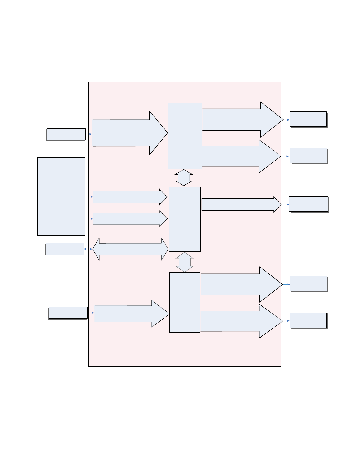
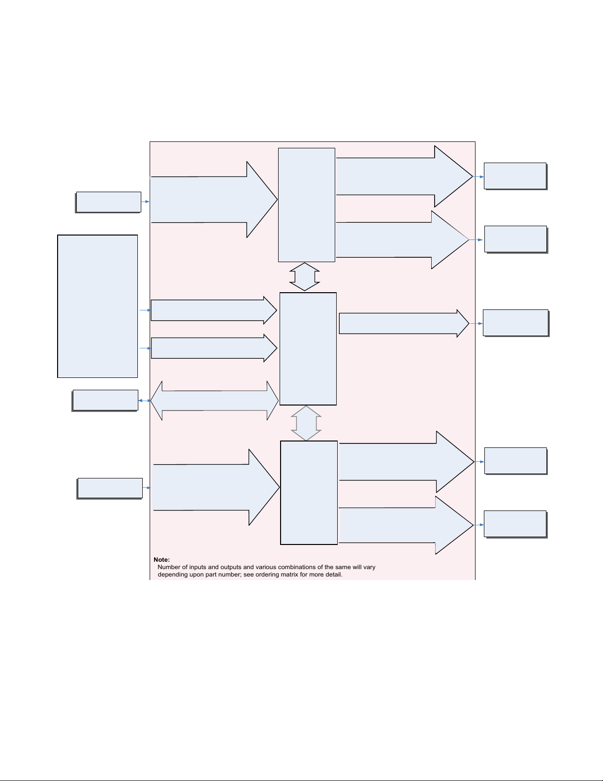
System Diagrams
Note:
Number of inputs and outputs and various combinations of the same will vary
depending upon part number; see ordering matrix for more detail.
Function Key
Programmable Event
Digital Output (or Input) 5 & 6
(optional) none, switched dc
Digital Input (or Output) 5 & 6
(optional) none, switch, volts dc
Current
Transformer
Board
(optional)
Slot B
Inputs
Outputs
- None
- Idle set point
- Tune
- Alarm clear, request
- Force alarm
- Silence alarm
- Manual/auto mode
- Control outputs off
- Remote set point
enable
- Lock keypad
- TRU-TUNE+® disable
- Loop & alarms off
- Profile disable
- Profile hold/resume
- Profile start
- Profile start/stop
- Restore user settings
- Event inputs
Analog Input 1
none, Thermocouple, RTD (100Ω,
1kΩ), Thermistor 5kΩ, 10kΩ, 20kΩ,
40kΩ) Process (V, mV, mA) or 1k
Potentiometer
Output 1
none, switched dc/open collector, 5A
mechanical relay (form C), process
(V, mA), or 0.5A SSR (form A)
Output 2
none, 15A NO-ARC, switched dc,
5A mechanical relay (form A), or
0.5A SSR (form A)
Analog Input 2
Current Transformer
PID
Controller
(Optional -
Ramp/Soak max 4
files, 40 steps)
Slot A
(Optional)
Input Sensor
off, heat, cool
alarm, retransmit,
duplex, event
off, heat, cool
alarm, event
off, heat, cool
alarm, retransmit,
duplex, event
off, heat, cool
alarm, event
off, heat, cool
alarm, event
Modbus
Address
1 - 247
Standard Bus
Zone Address
1 - 16
Supervisory &
Power Board
Slot C
Current
Transformer
EIA-485 Communication
Standard Bus
(optional Modbus RTU)
RUI, Controllers,
PLC, PC or HMI
Output 3
none, switched dc/open collector, 5A
mechanical relay (form C), process
(V, mA), or 0.5A SSR (form A)
Output 4
none, 15A NO-ARC, switched dc,
5A mechanical relay (form A), or
0.5A SSR (form A)
Current Monitoring - with Current Transformer, without Communications Card
• Detects heater current flow
• Provides an alarm indication of a failed-load issue.
Watlow PM PLUS™ 6 • 13 • Chapter 1 Overview
Page 14
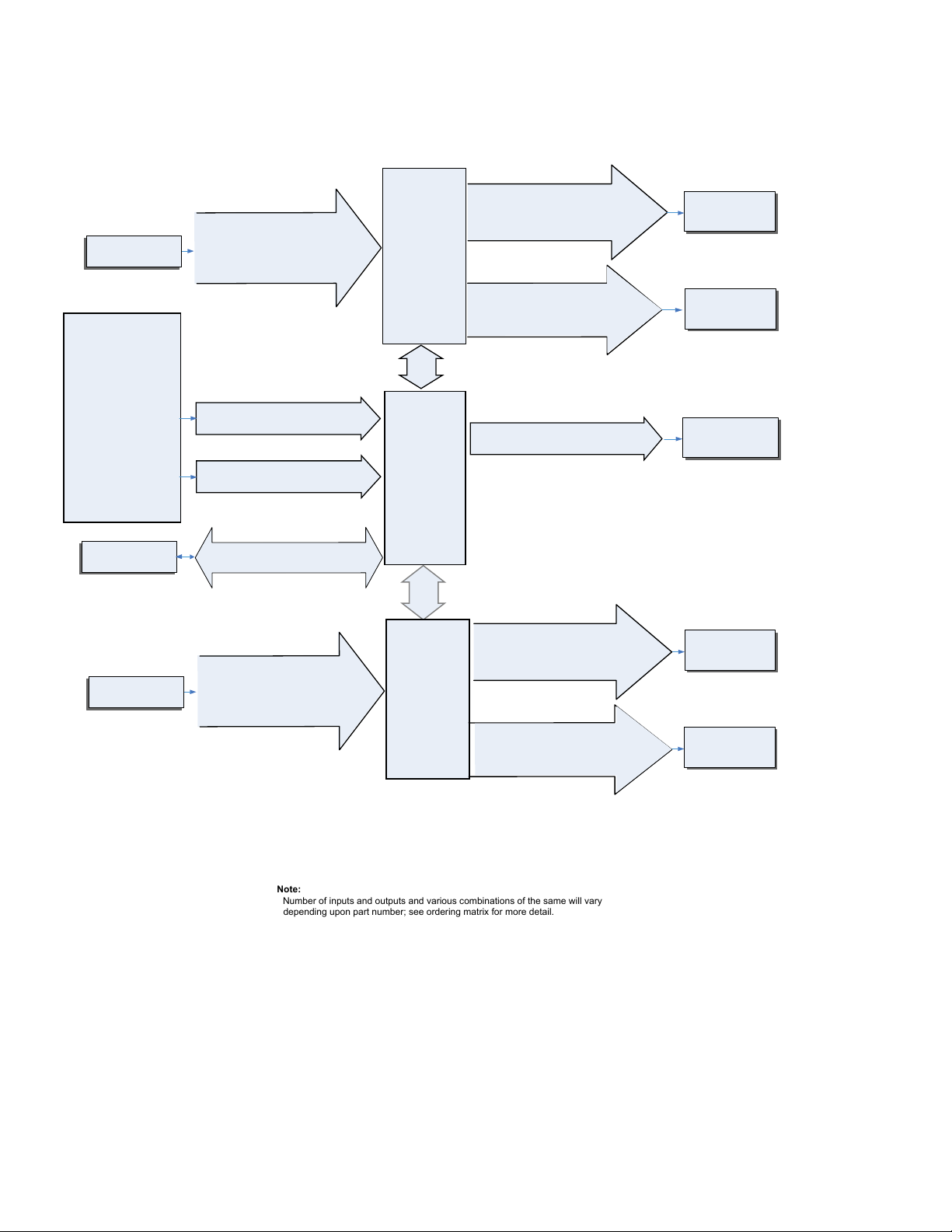
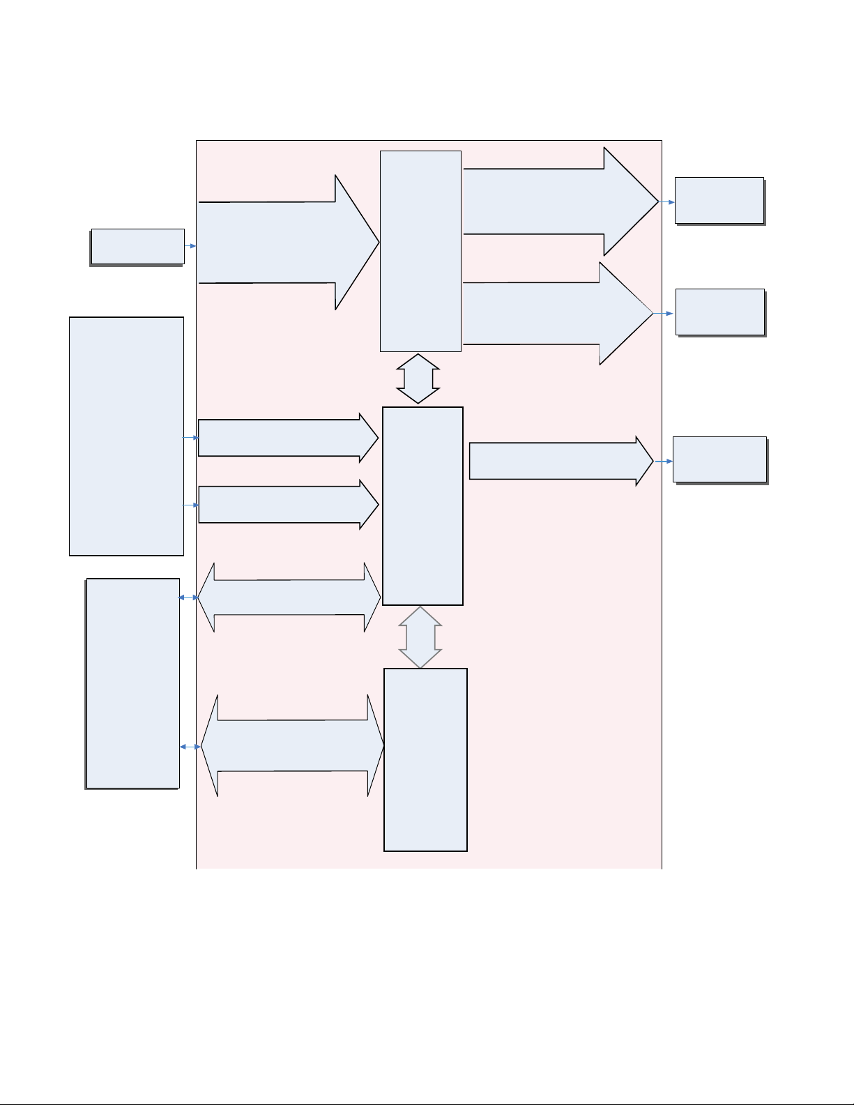
Remote Set Point Operation With Auxillary Input, Without Communications Card
Note:
Number of inputs and outputs and various combinations of the same will vary
depending upon part number; see ordering matrix for more detail.
• Remote Set Point Operation supports efficient set point manipulation from a remote device, such as a
master control or PLC.
Input
Functions
Input Sensor
- None
- Idle set point
- Tune
- Alarm clear, request
- Force alarm
- Silence alarm
- Manual/auto mode
- Control outputs off
- Remote set point
enable
- Lock keypad
- TRU-TUNE+
- Loop & alarms off
- Profile disable
- Profile hold/resume
- Profile start
- Profile start/stop
- Restore user settings
- Event inputs
®
disable
RUI, Controllers,
PLC, PC or HMI
Analog Input 1
none, Thermocouple, RTD (100Ω,
1kΩ), Thermistor 5kΩ, 10kΩ, 20kΩ,
40kΩ) Process (V, mV, mA) or 1k
Potentiometer
Digital Input (or Output) 5 & 6
(optional) none, switch, volts dc
Function Key
Programmable Event
EIA-485 Communication
Standard Bus
(optional Modbus RTU)
PID
Controller
(Optional -
Ramp/Soak max 4
files, 40 steps)
Slots A
(Optional)
Modbus
Address 1 - 247
Standard Bus
Zone Address
1 - 16
Supervisory &
Power Board
Slot C
Output 1
none, switched dc/open collector, 5A
mechanical relay (form C), process
(V, mA), or 0.5A SSR (form A)
Output 2
none, 15A NO-ARC, switched dc,
5A mechanical relay (form A), or
0.5A SSR (form A)
Digital Output (or Input) 5 & 6
(optional) none, switched dc
Output
Functions
off, heat, cool
alarm, retransmit,
duplex, event
off, heat, cool
alarm, event
off, heat, cool
alarm, event
Input Sensor
Analog Input 2
none, CT, Thermocouple, RTD (100
Ω, 1kΩ), Thermistor 5kΩ, 10kΩ,
20kΩ, 40kΩ) Process (V, mV, mA)
or 1k Potentiometer
Auxillary
Input
(optional)
Slot B
Output 3
none, switched dc/open collector, 5A
mechanical relay (form C), process
(V, mA), or 0.5A SSR (form A)
Output 4
none, 15A NO-ARC, switched dc,
5A mechanical relay (form A), or
0.5A SSR (form A)
off, heat, cool
alarm, retransmit,
duplex, event
off, heat, cool
alarm, event
Watlow PM PLUS™ 6 • 14 • Chapter 1 Overview
Page 15
Integrated PID and Limit Controller with Limit, Without Communications Card
Note:
Number of inputs and outputs and various combinations of the same will vary
depending upon part number; see ordering matrix for more detail.
• Reduces wiring time and termination complexity compared to connecting separate products
• Reduces panel space
• Reduces installation costs
• Increases dependability with backup control sensor operation
• Increases user and equipment safety for over-under temperature conditions
Input
Functions
Input Sensor
- None
- Limit reset
- Idle set point
- Tune
- Alarm clear, request
- Force alarm
- Silence alarm
- Manual/auto mode
- Control outputs off
- Remote set point
enable
- Lock keypad
- TRU-TUNE+
- Loop & alarms off
- Profile disable
- Profile hold/resume
- Profile start
- Profile start/stop
- Restore user settings
- Event inputs
®
disable
RUI, Controllers,
PLC, PC or HMI
Analog Input 1
none, Thermocouple, RTD (100Ω,
1kΩ), Thermistor 5kΩ, 10kΩ, 20kΩ,
40kΩ) Process (V, mV, mA) or 1k
Potentiometer
Digital Input (or Output) 5 & 6
(optional) none, switch, volts dc
Function Key
Programmable Event
EIA-485 Communication
Standard Bus
(optional Modbus RTU)
PID
Controller
(Optional -
Ramp/Soak max 4
files, 40 steps)
Slots A
(Optional)
Modbus
Address 1 - 247
Standard Bus
Zone Address
1 - 16
Supervisory &
Power Board
Slot C
Output 1
none, switched dc/open collector, 5A
mechanical relay (form C), process
(V, mA), or 0.5A SSR (form A)
Output 2
none, 15A NO-ARC, switched dc,
5A mechanical relay (form A), or
0.5A SSR (form A)
Digital Output (or Input) 5 & 6
(optional) none, switched dc
Output
Functions
off, heat, cool
alarm, retransmit,
duplex, event
off, heat, cool
alarm, event
off, heat, cool
alarm, event
Input Sensor
Analog Input 2
none, CT, Thermocouple, RTD (100
Ω, 1kΩ), Thermistor 5kΩ, 10kΩ,
20kΩ, 40kΩ) Process (V, mV, mA)
or 1k Potentiometer
Limit Controller
Board
(optional)
Slot B
Output 3
none, switched dc/open collector, 5A
mechanical relay (form C), process
(V, mA), or 0.5A SSR (form A)
Output 4
5A mechanical relay (form A)
If Limit, this output must
be Limit
off, heat, cool
alarm, retransmit,
duplex or event
Limit
Watlow PM PLUS™ 6 • 15 • Chapter 1 Overview
Page 16
Expanded Serial Communications
Function Key
Programmable Event
Digital Output (or Input) 5 & 6
(optional) none, switched dc
Digital Input (or Output) 5 & 6
(optional) none, switch, volts dc
Input
Functions
Output
Functions
- None
- Idle set point
- Tune
- Alarm clear, request
- Force alarm
- Silence alarm
- Manual/auto mode
- Control outputs off
- Remote set point
enable
- Lock keypad
- TRU-TUNE+
®
disable
- Loop & alarms off
- Profile disable
- Profile hold/resume
- Profile start
- Profile start/stop
- Restore user settings
- Event inputs
Analog Input 1
none, CT, Thermocouple, RTD (100
Ω, 1kΩ), Thermistor 5kΩ, 10kΩ,
20kΩ, 40kΩ) Process (V, mV, mA)
or 1k Potentiometer
Output 1
none, switched dc/open collector, 5A
mechanical relay (form C), process
(V, mA), or 0.5A SSR (form A)
Output 2
none, 15A NO-ARC, switched dc,
5A mechanical relay (form A), or
0.5A SSR (form A)
PID
Controller
(Optional -
Ramp/Soak max 4
files, 40 steps)
Slot A
(Optional)
Input Sensor
off, heat, cool
alarm, retransmit,
duplex, event
off, heat, cool
alarm, event
off, heat, cool
alarm, event
EIA-485 Communication
Standard Bus
(optional Modbus RTU)
RUI, Controllers,
PLC, PC or HMI
Communications
EIA 232/485 Modbus RTU/TCP,
EtherNet/IP, DeviceNet, Profibus
Modbus Address
1 - 247
Standard Bus
Zone Address
1 - 16
Supervisory &
Power Board
Slot C
Communications
Board
Slot B
• Supports network connectivity to a PC or PLC
• Available in a wide range of protocol choices, including Modbus® RTU, EtherNet/IP™, Modbus® TCP
Watlow PM PLUS™ 6 • 16 • Chapter 1 Overview
Page 17
Chapter 2: Installation
D
C
7
6
5
4
3
2
1
REVISION
REV. DESCRIPTION DAT E ECO
1 PROTO
XX/XX/20XX
-
2 Updated
5/31/2019
--
4.164 in.
(105.8 mm)
0.4 in.
(10.2 mm)
D
C
4
3
2
1
REVISION
REV. DESCRIPTION DAT E ECO
1 PROTO
XX/XX/20XX
-
2 Updated
5/31/2019
--
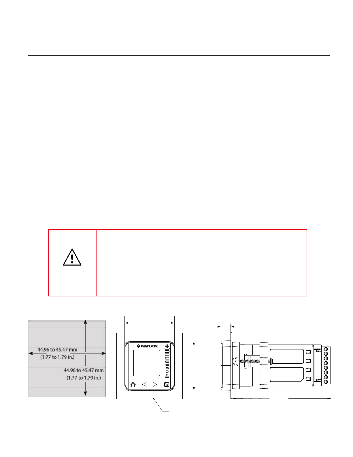
Installing the Device
1. Make the panel cutout using the measurements shown here. We recommend a minimum of 21.6 mm
between panel cutouts.
2. Remove the green terminal connectors and the mounting collar assembly.
3. Insert the controller into the panel cutout from the front.
4. Orient the collar base so the flat side faces front and the screw openings are on the sides, then slide the base
over the back of the controller.
5. Slide the mounting bracket over the controller with the screws aligned to the collar base.
6. Push the bracket gently but firmly until the hooks snap into the slots in the case.
7. Tighten the two #6-19 x 1.5" screws with a Phillips screwdriver until the device is flush to the panel
(3 to 4 in-lbs torque).
8. Secure screws from the back with Philips screwdriver.
Reinstall the terminal connectors to their original locations. (Or first connect field wiring as indicated in this
guide and then reinstall the connectors).
• This equipment is suitable for use in Class 1, Div. 2, Groups A, B, C
and D or Non-Hazardous locations only. Temperature Code T4A. Note:
Class 1, Div 2 is only valid if the last 2 characters in the part # are "12".
• EXPLOSION HAZARD. Substitution of component may impair
suitability for Class 1, Div. 2.
• EXPLOSION HAZARD. Do not disconnect equipment unless power has
been switched off or the area is known to be nonhazardous.
2.10 in.
(53.3 mm)
2.10 in.
(53.3 mm)
(10.2 mm)
0.4 in.
4.164 in.
(105.8 mm)
Mounting Panel
Watlow PM PLUS™ 6 • 17 • Chapter 2: Installation
Page 18

Wiring Notes
Maximum wire size termination and torque rating:
0.0507 to 3.30 mm2 (30
to 12 AWG) single-wire
termination or two 1.31
mm2 (16 AWG)
0.56 Nm (5.0 in-lb.)
torque
Adjacent terminals may
be labeled differently
depending on the model
number.
Do not connect wires to
unused terminals.
Maintain electrical isolation between analog
input 1, digital inputoutputs, switched dc/
open collector outputs
and process outputs to
prevent ground loops.
This equipment is suitable for use in CLASS
I, DIVISION 2, Groups
A, B, C and D or NonHazardous locations only.
Temperature Code T4A
Wiring Warnings
Use National Electric
(NEC) or other countryspecic standard wiring
and safety practices
when wiring this controller to a power source,
electrical sensors or peripheral devices. Failure
to do so may result in
damage to equipment
and property, and/or injury or loss of life.
Explosion Hazard - Dry
contact closure Digital
Inputs shall not be used
in Class I Division 2 Hazardous Locations unless
switch used is approved
for this application.
Explosion Hazard – Substitution of component
may impair suitability for
CLASS I, DIVISION 2.
Explosion Hazard - Do
not disconnect while the
circuit is live or unless
the area is known to be
free of ignitable concentrations of ammable
substances.
ç
Wiring Your New PM PLUS™
Inputs and Outputs
Input 1Input
2
Slot A Slot B
T1
S1
R1
Slot A Slot B
Slot A Slot B
X1 X3 common Output 1: PM _ _ _[C] _ - _ _ _ _ _ _ _
W1 W3
Y1 Y3
Slot A Slot B
W2 W4 mA ac Output 2: PM _ _ _ _ [C] - _ _ _ _ _ _ _
Y2 Y4 mA ac
Slot A Slot B
F1 F3 voltage or current - Output 1: PM _ _ _ [F] _ - _ _ _ _ _ _ _
G1 G3 voltage +
H1 H3 current +
Slot A Slot B
L1 L3 normally open Output 1: PM _ _ _ [E] _ - _ _ _ _ _ _ _
K1 K3 common
K1 J3 normally closed
Slot A Slot B
L2 L4 normally open Output 2: PM _ _ _ _ [H] - _ _ _ [H*] _ _
K2 K4 common
Slot B
CB
CA
CC
CB
CA
C5
C3
C2
T2
S2
R2
T2
S2
Modbus® RTU 232/485 Communications
Modbus® RTU EIA-485 T+/R+
Modbus® RTU EIA-485 T-/RModbus® RTU EIA-485 common
Modbus® RTU EIA-485 T+/R+
Modbus® RTU EIA-485 T-/RModbus® RTU EIA-232 common
Modbus® RTU EIA-232 to DB9 pin 2
Modbus® RTU EIA-232 to DB9 pin 3
DeviceNet™ Communications
UNIVERSAL, RTD, THERMISTOR INPUTS
S2 (RTD) or current +
S3 (RTD), thermocouple -, current -, potentiometer wiper,
thermistor or volts S1 (RTD), thermocouple +, volts
+, potentiometer or thermistor
CURRENT TRANSFORMER INPUT 2
mA ac
mA ac
SWITCHED DC / OPEN COLLECTOR OUTPUTS
DC-
DC+
SWITCHED DC OUTPUTS
UNIVERSAL PROCESS OUTPUTS
MECHANICAL RELAY 5A, FORM C OUTPUTS
NO-ARC 15A FORM A
Input Function Configuration Code
Input 1: all configurations
Input 2: PM _ _ _ _ _ - _ [R,L] _ _ _ _ _
Input 2: PM _ _ _ _ _ - _ [T] _ _ _ _ _
Output 3: PM _ _ _ _ _ - _ _ [C] _ _ _ _
Output 4: PM _ _ _ _ _ - _ _ _ [C] _ _ _
Output 3: PM _ _ _ _ _ - _ _ [F] _ _ _ _
Output 3: PM _ _ _ _ _ - _ _ [E] _ _ _ _
_
Communications
Slot B: PM6 _ _ _ _ - [2] A A A _ _ _
Watlow PM PLUS™ 6 • 18 • Chapter 2: Installation
Page 19

Wiring Notes
Maximum wire size
termination and torque
rating:
0.0507 to 3.30 mm2 (30
to 12 AWG) single-wire
termination or two 1.31
mm2 (16 AWG)
0.56 Nm (5.0 in-lb.)
torque
Adjacent terminals may
be labeled differently
depending on the model
number.
Do not connect wires to
unused terminals.
Maintain electrical isolation between analog
input 1, digital inputoutputs, switched dc/
open collector outputs
and process outputs to
prevent ground loops.
This equipment is suitable for use in CLASS I,
DIVISION 2, Groups A,
B, C and D or Non-Hazardous locations only.
Temperature Code T4A
Wiring Warnings
Use National Electric
(NEC) or other countryspecic standard wiring
and safety practices
when wiring this controller to a power source,
electrical sensors or peripheral devices. Failure
to do so may result in
damage to equipment
and property, and/or injury or loss of life.
Explosion Hazard - Dry
contact closure Digital
Inputs shall not be used
in Class I Division 2 Hazardous Locations unless
switch used is approved
for this application.
Explosion Hazard – Substitution of component
may impair suitability for
CLASS I, DIVISION 2.
Explosion Hazard - Do
not disconnect while the
circuit is live or unless
the area is known to be
free of ignitable concentrations of ammable
substances.
ç
V+
CH
SH
CL
V-
DeviceNet power
Positive side of DeviceNet bus
Shield interconnect
Negative side of DeviceNet bus
DeviceNet power return
Slot B: PM6 _ _ _ _ - [5] A A A _ _ _
EtherNet/IP™ and Modbus® TCP
E8
E7
E6
E5
E4
E3
E2
E1
unused
unused
EtherNet/IP and Modbus® TCP receive unused
unused
EtherNet/IP and Modbus® TCP receive +
EtherNet/IP and Modbus® TCP transmit EtherNet/IP and Modbus® TCP transmit +
Slot B: PM6 _ _ _ _ - [3] A A A _ _ _
Profibus DP Communications
VP
B
A
DG
trB
B
A
trA
Voltage Potential
EIA-485 T+/R+
EIA-485 T-/RDigital ground (common)
Termination resistor B
EIA-485 T+/R+
EIA-485 T-/RTermination resistor A
Slot B: PM6 _ _ _ _ - [6] AAA _ _ _
J1939 CAN bus Communications
CL
CH
SH
V+
V-
Negative side of CAN bus
Positive side of CAN bus
Shield interconnect
CAN bus power
CAN bus power return
Slot B: PM6 _ _ _ _ - [7] A A A _ _ _
Slot C Power or Communications Wiring
Slot C Terminal Function Configuration
98
99
CC
CA
CB
CF
CD
CE
B5
D6
D5
Power input: ac or dc+
Power input: ac or dc-
®
Standard Bus or Modbus
common
Standard Bus or Modbus® RTU EIA-485
T-/RStandard Bus or Modbus® RTU EIA-485
T+/R+
Standard Bus EIA-485 common
Standard Bus EIA-485 T-/RStandard Bus EIA-485 T+/R+
Digital input-output common
Digital input or output 6
Digital input or output 5
RTU EIA-485
all
PM _ _ _ _ _ - [1] _ _ _ _ _ _
PM _ _ _ _ _ - [A,D,2,3,5] _ _ _ _ _ _
PM _ _ [2] _ _ - _ _ _ _ _ _ _
PM _ _ [4] _ _ - _ _ _ _ _ _ _
Watlow PM PLUS™ 6 • 19 • Chapter 2: Installation
Page 20
Wiring Notes
Maximum wire size termination and torque rating:
0.0507 to 3.30 mm2 (30
to 12 AWG) single-wire
termination or two 1.31
mm2 (16 AWG)
0.56 Nm (5.0 in-lb.)
torque
Adjacent terminals may
be labeled differently
depending on the model
number.
Do not connect wires to
unused terminals.
Maintain electrical isolation between analog
input 1, digital inputoutputs, switched dc/
open collector outputs
and process outputs to
prevent ground loops.
This equipment is suitable for use in CLASS
I, DIVISION 2, Groups
A, B, C and D or NonHazardous locations only.
Temperature Code T4A
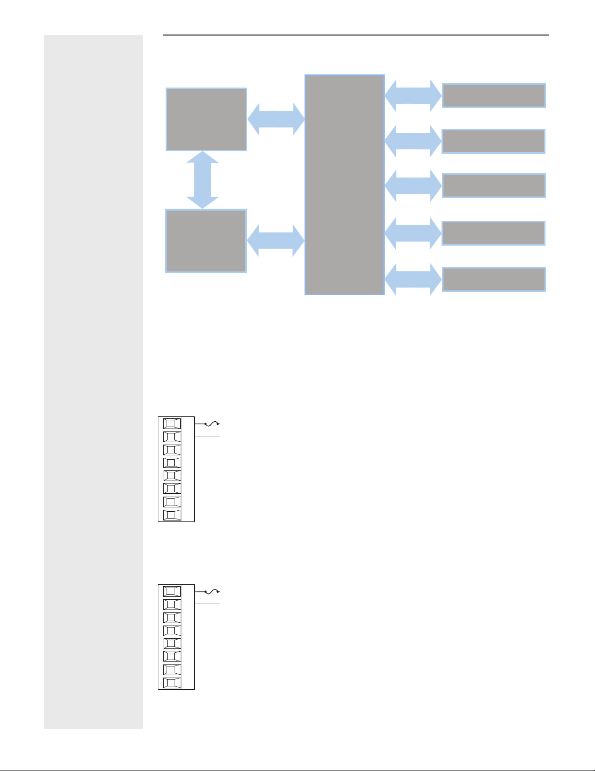
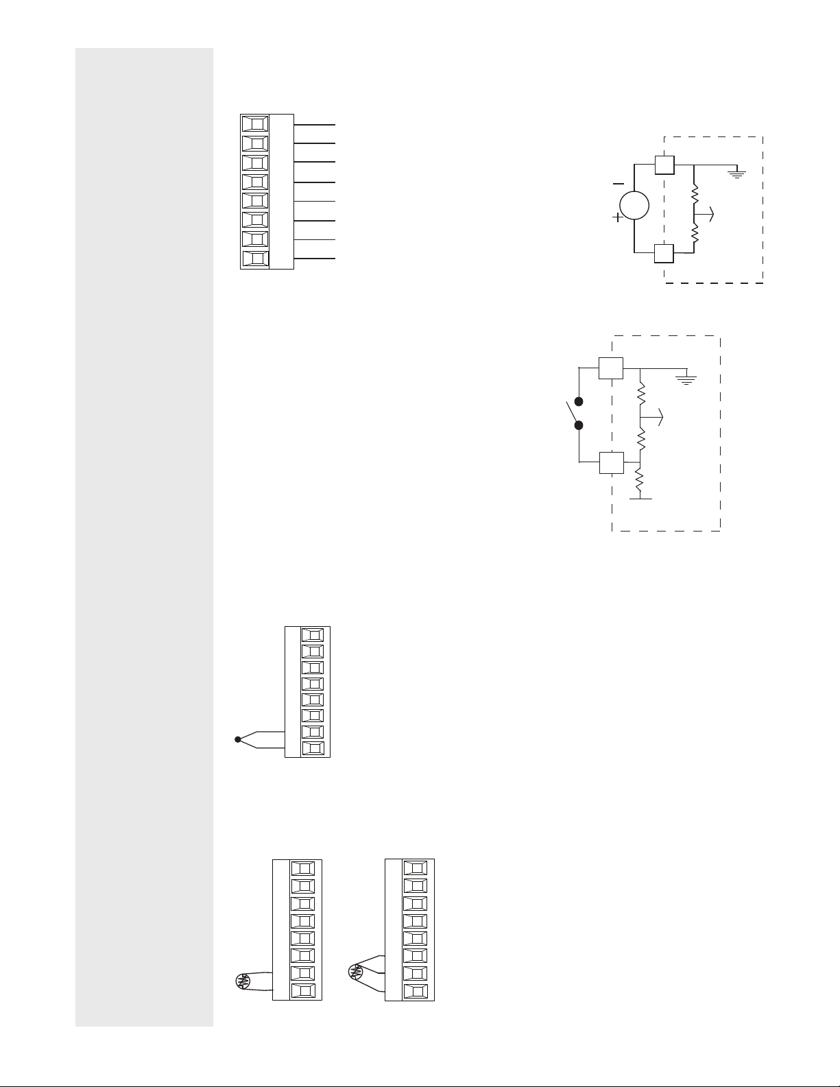
Isolation Block Diagram
Controller Power Supply
12 to 40VDC
20 to 28VAC
100 to 240VAC
Safety Isolation
Mechanical Relay,
Solid-State Relay,
NO-ARC Relay
Outputs
Safety Isolation
Controller
Low Voltage Power Bus
Safety Isolation
Low-voltage Isolation: 42V peak
Safety Isolation: 2300VAC
No Isolation
No Isolation
Low Voltage
Isolation
Low-voltage
Isolation
Low-voltage
Isolation
Digital Inputs & Outputs
5-12
Switched DC, Open Collector,
Process outputs
Analog Input 1
Analog Input 2
Communications Ports
Wiring Warnings
ç
Use National Electric
(NEC) or other countryspecic standard wiring
and safety practices
when wiring this controller to a power source,
electrical sensors or peripheral devices. Failure
to do so may result in
damage to equipment
and property, and/or injury or loss of life.
Explosion Hazard - Dry
contact closure Digital
Inputs shall not be used
in Class I Division 2 Hazardous Locations unless
switch used is approved
for this application.
Explosion Hazard – Substitution of component
may impair suitability for
CLASS I, DIVISION 2.
Explosion Hazard - Do
not disconnect while the
circuit is live or unless
the area is known to be
free of ignitable concentrations of ammable
substances.
Low Power
PM_ _ [3,4] _ _ - _ _ _ _ _ _ _
Slot C
98
99
CF
CD
CE
B5
D6
D5
power
power
fuse
• Minimum/Maximum Ratings
• 12 to 40VDC
• 20 to 28VAC) Semi Sig F47
• 47 to 63 Hz
• 10VA maximum power consumption
High Power
PM_ _ [1,2] _ _ - _ _ _ _ _ _ _
Slot C
98
99
CF
CD
CE
B5
D6
D5
power
power
fuse
• Minimum/Maximum Ratings
• 85 to 264VAC
• 100 to 240VAC Semi Sig F47
• 47 to 63 Hz
• 10VA maximum power consumption
Watlow PM PLUS™ 6 • 20 • Chapter 2: Installation
Page 21
Wiring Notes
Maximum wire size
termination and torque
rating:
0.0507 to 3.30 mm2 (30
to 12 AWG) single-wire
termination or two 1.31
mm2 (16 AWG)
0.56 Nm (5.0 in-lb.)
torque
Adjacent terminals may
be labeled differently
depending on the model
number.
Do not connect wires to
unused terminals.
Maintain electrical isolation between analog
input 1, digital inputoutputs, switched dc/
open collector outputs
and process outputs to
prevent ground loops.
This equipment is suitable for use in CLASS I,
DIVISION 2, Groups A,
B, C and D or Non-Hazardous locations only.
Temperature Code T4A
Wiring Warnings
ç
Use National Electric
(NEC) or other countryspecic standard wiring
and safety practices
when wiring this controller to a power source,
electrical sensors or peripheral devices. Failure
to do so may result in
damage to equipment
and property, and/or injury or loss of life.
Explosion Hazard - Dry
contact closure Digital
Inputs shall not be used
in Class I Division 2 Hazardous Locations unless
switch used is approved
for this application.
Explosion Hazard – Substitution of component
may impair suitability for
CLASS I, DIVISION 2.
Explosion Hazard - Do
not disconnect while the
circuit is live or unless
the area is known to be
free of ignitable concentrations of ammable
substances.
Digital Input 5 - 6
PM _ _ [2,4] _ _ - _ _ _ _ _ _ _
Slot C
98
99
CF
CD
CE
B5
D6
D5
common
DC Input
DC Input
Digital Input
• Update rate 10 Hz
• Dry contact or dc voltage
DC Voltage
• Input not to exceed 36V (dc) at
3mA
• Input active when > 3V (dc) @
0.25mA
• Input inactive when < 2V
Dry Contact
Voltage Input
• Input inactive when > 500Ω
• Input active when < 100Ω
• Maximum short circuit 13mA
Dry Contact
Input 1, 2 Thermocouple
Input 1: PM _ [C,R] _ _ _ - _ _ _ _ _ _ _ (S1/R1)
Input 2: PM _ _ _ _ _ - _ [C,R,L] _ _ _ _ _ (S2/R2)
Slot A,B
• 2kΩ maximum source resistance
• >20MΩ input impedance
• 3µA open-sensor detection
• Thermocouples are polarity sensitive. The negative lead (usually red)
must be connected to S1 and/or S2.
• To reduce errors, the extension wire for thermocouples must be of the
-
S_
+
R_
same alloy as the thermocouple.
Input 1, 2 RTD
Input 1: PM _ [C,R,] _ _ _ - _ _ _ _ _ _ _ (S1/R1),(T1/S1/R1)
Input 2: PM _ _ _ _ _ - _ [C,R,L] _ _ _ _ _ (S2/R2), (T2/S2/R2)
Slot A,B
S3
S_
S1
R_
Slot A, B
S2
T_
S_
S3
R_
S1
• Platinum, 100 and 1kΩ @ 0°C
• Calibration to DIN curve (0.00385 Ω/Ω/°C)
• 20Ω total lead resistance
• RTD excitation current of 0.09mA typical. Each ohm of
lead resistance may affect the reading by 0.03°C.
• For 3-wire RTDs, the S1 lead (usually white) must be
connected to R1 and/or R2
• For accuracy use a 3-wire RTD to compensate for
lead-length resistance. All three lead wires must have
the same resistance
_
B
_
D
Vdc
common
24 Vdc
_
B
_
D
common
Watlow PM PLUS™ 6 • 21 • Chapter 2: Installation
Page 22
Wiring Notes
amperes
Maximum wire size termination and torque rating:
0.0507 to 3.30 mm2 (30
to 12 AWG) single-wire
termination or two 1.31
mm2 (16 AWG)
0.56 Nm (5.0 in-lb.)
torque
Adjacent terminals may
be labeled differently
depending on the model
number.
Do not connect wires to
unused terminals.
Maintain electrical isolation between analog
input 1, digital inputoutputs, switched dc/
open collector outputs
and process outputs to
prevent ground loops.
This equipment is suitable for use in CLASS
I, DIVISION 2, Groups
A, B, C and D or NonHazardous locations only.
Temperature Code T4A
Wiring Warnings
ç
Use National Electric
(NEC) or other countryspecic standard wiring
and safety practices
when wiring this controller to a power source,
electrical sensors or peripheral devices. Failure
to do so may result in
damage to equipment
and property, and/or injury or loss of life.
Explosion Hazard - Dry
contact closure Digital
Inputs shall not be used
in Class I Division 2 Hazardous Locations unless
switch used is approved
for this application.
Explosion Hazard – Substitution of component
may impair suitability for
CLASS I, DIVISION 2.
Explosion Hazard - Do
not disconnect while the
circuit is live or unless
the area is known to be
free of ignitable concentrations of ammable
substances.
Input 1, 2 Process
Input 1: PM _ [C,R,] _ _ _ - _ _ _ _ _ _ _ (-S1/+R1),(+T1/-S1)
Input 2: PM _ _ _ _ _ - _ [C,R,L] _ _ _ _ _ (-S2/+R2),(+T2/-S2)
Slot A, B
Slot A, B
• 0 to 20mA @ 100Ω input impedance
• 0 to 10VDC @ 20kΩ input impedance
• 0 to 50mVDC @ 20kΩ input impedance
• Scalable
+
T_
-
S_
+
R_
volts
-
S_
Input 1,2 Potentiometer
Input 1: PM _ [C,R] _ _ _ - _ _ _ _ _ _ _ (S1/R1)
Input 2: PM _ _ _ _ _ - _ [C,R,L] _ _ _ _ _ (S2/R2)
• Use a 1kΩ potentiometer.
CW
CCW
Slot A, B
S_
R_
Input 1, 2 Thermistor
Input 1: PM _ [J,N] _ _ _ _-_ _ _ _ _ _ _ (S1/R1)
Input 2: PM _ _ _ _ _ - _ [J,P,M] _ _ _ _ _ (S2/R2)
Slot A, B
• >20MΩ input impedance
• 3µA open-sensor detection
S_
R_
Input 2 Current Transformer
PM _ _ _ _ _ - _ [T] _ _ _ _ _
Slot B
T2
S2
• Input range is 0 to 50mA
• Current transformer part number: 16-0246
• 100Ω input impedance
• Response time: 1 second maximum
• Accuracy +/-1 mA typical
Watlow PM PLUS™ 6 • 22 • Chapter 2: Installation
Page 23
12A
Is = IpT/R = 50mA
ent
Wiring Notes
Maximum wire size
termination and torque
rating:
0.0507 to 3.30 mm2 (30
to 12 AWG) single-wire
termination or two 1.31
mm2 (16 AWG)
0.56 Nm (5.0 in-lb.)
torque
Adjacent terminals may
be labeled differently
depending on the model
number.
Do not connect wires to
unused terminals.
Maintain electrical isolation between analog
input 1, digital inputoutputs, switched dc/
open collector outputs
and process outputs to
prevent ground loops.
This equipment is suitable for use in CLASS I,
DIVISION 2, Groups A,
B, C and D or Non-Hazardous locations only.
Temperature Code T4A
Wiring Warnings
ç
Use National Electric
(NEC) or other countryspecic standard wiring
and safety practices
when wiring this controller to a power source,
electrical sensors or peripheral devices. Failure
to do so may result in
damage to equipment
and property, and/or injury or loss of life.
Explosion Hazard - Dry
contact closure Digital
Inputs shall not be used
in Class I Division 2 Hazardous Locations unless
switch used is approved
for this application.
Explosion Hazard – Substitution of component
may impair suitability for
CLASS I, DIVISION 2.
Explosion Hazard - Do
not disconnect while the
circuit is live or unless
the area is known to be
free of ignitable concentrations of ammable
substances.
Example Current Transformer:
L2 L1
3A x 4
Turns around CT
12A
:
x 4 = 48A
48mA
CT Secondary Current
CT Primary Current
Turns around CT
Total current
Digital Output 5 - 6
PM _ _ [2,4] _ _ - _ _ _ _ _ _ _
Slot C
98
99
CF
CD
CE
common
B5
switched dc
D6
switched dc
D5
Digital Output
• SSR drive signal
• Update rate 10 Hz
• Maximum open circuit voltage is
22 to 25V (dc)
• PNP transistor source
• Typical drive; 21mA @ 4.5V (dc)
for DO5, and 11mA @ 4.5V for
DO6
• Current limit 24mA for Output 5
and 12mA Output 6
• Output 5 capable of driving one
3-pole DIN-A-MITE
• Output 6 capable of driving one
1-pole DIN-A-MITE
Fuse
SSR
CT Ratio R = 1000:1
48mA
Output N
Controller
CT Input
p(full scale)
CSC = I
CSI = Output N
I
s = Current in secondary of current transformer
Ip = Current in primary of current transformer
T = Number of turns through the primary of the transformer
R = Number of turns in the secondary of the current
transformer (Turns ratio, assuming one primary turn)
CSC = Current Scaling (parameter found in Current Menu
of Setup Page)
CSI = Current Source Instance (parameter found in Curr
Menu of Setup Page)
= 50mA(R)/T
24VDC
switched dc outputs
D5
D6
B5
Internal Circuitry
Watlow PM PLUS™ 6 • 23 • Chapter 2: Installation
Page 24
Wiring Notes
Maximum wire size termination and torque rating:
0.0507 to 3.30 mm2 (30
to 12 AWG) single-wire
termination or two 1.31
mm2 (16 AWG)
0.56 Nm (5.0 in-lb.)
torque
Adjacent terminals may
be labeled differently
depending on the model
number.
Do not connect wires to
unused terminals.
Maintain electrical isolation between analog
input 1, digital inputoutputs, switched dc/
open collector outputs
and process outputs to
prevent ground loops.
This equipment is suitable for use in CLASS
I, DIVISION 2, Groups
A, B, C and D or NonHazardous locations only.
Temperature Code T4A
Wiring Warnings
Use National Electric
(NEC) or other countryspecic standard wiring
and safety practices
when wiring this controller to a power source,
electrical sensors or peripheral devices. Failure
to do so may result in
damage to equipment
and property, and/or injury or loss of life.
Explosion Hazard - Dry
contact closure Digital
Inputs shall not be used
in Class I Division 2 Hazardous Locations unless
switch used is approved
for this application.
Explosion Hazard – Substitution of component
may impair suitability for
CLASS I, DIVISION 2.
Explosion Hazard - Do
not disconnect while the
circuit is live or unless
the area is known to be
free of ignitable concentrations of ammable
substances.
ç
Watlow PM PLUS™ 6 • 24 • Chapter 2: Installation
Page 25
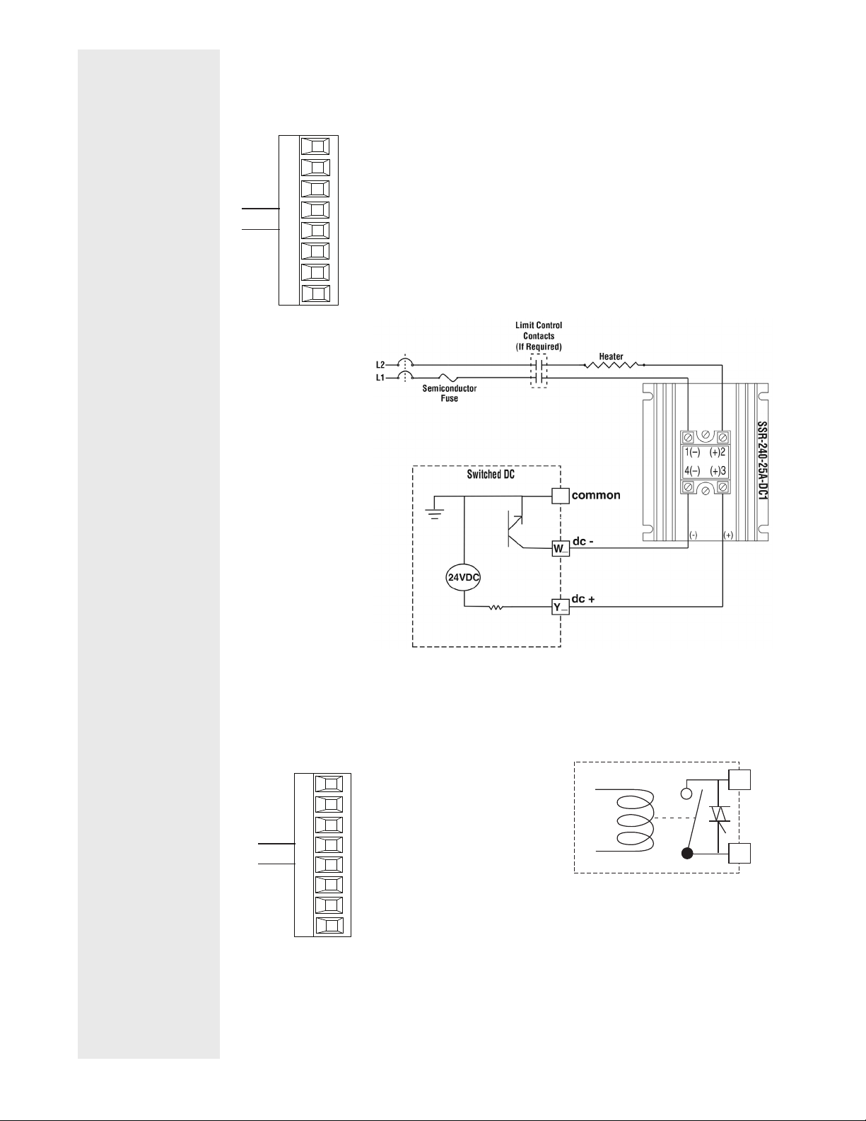
Wiring Notes
Limit Control
SSR-240-25A-DC1
Maximum wire size
termination and torque
rating:
0.0507 to 3.30 mm2 (30
to 12 AWG) single-wire
termination or two 1.31
mm2 (16 AWG)
0.56 Nm (5.0 in-lb.)
torque
Adjacent terminals may
be labeled differently
depending on the model
number.
Do not connect wires to
unused terminals.
Maintain electrical isolation between analog
input 1, digital inputoutputs, switched dc/
open collector outputs
and process outputs to
prevent ground loops.
This equipment is suitable for use in CLASS I,
DIVISION 2, Groups A,
B, C and D or Non-Hazardous locations only.
Temperature Code T4A
Wiring Warnings
ç
Use National Electric
(NEC) or other countryspecic standard wiring
and safety practices
when wiring this controller to a power source,
electrical sensors or peripheral devices. Failure
to do so may result in
damage to equipment
and property, and/or injury or loss of life.
Explosion Hazard - Dry
contact closure Digital
Inputs shall not be used
in Class I Division 2 Hazardous Locations unless
switch used is approved
for this application.
Explosion Hazard – Substitution of component
may impair suitability for
CLASS I, DIVISION 2.
Explosion Hazard - Do
not disconnect while the
circuit is live or unless
the area is known to be
free of ignitable concentrations of ammable
substances.
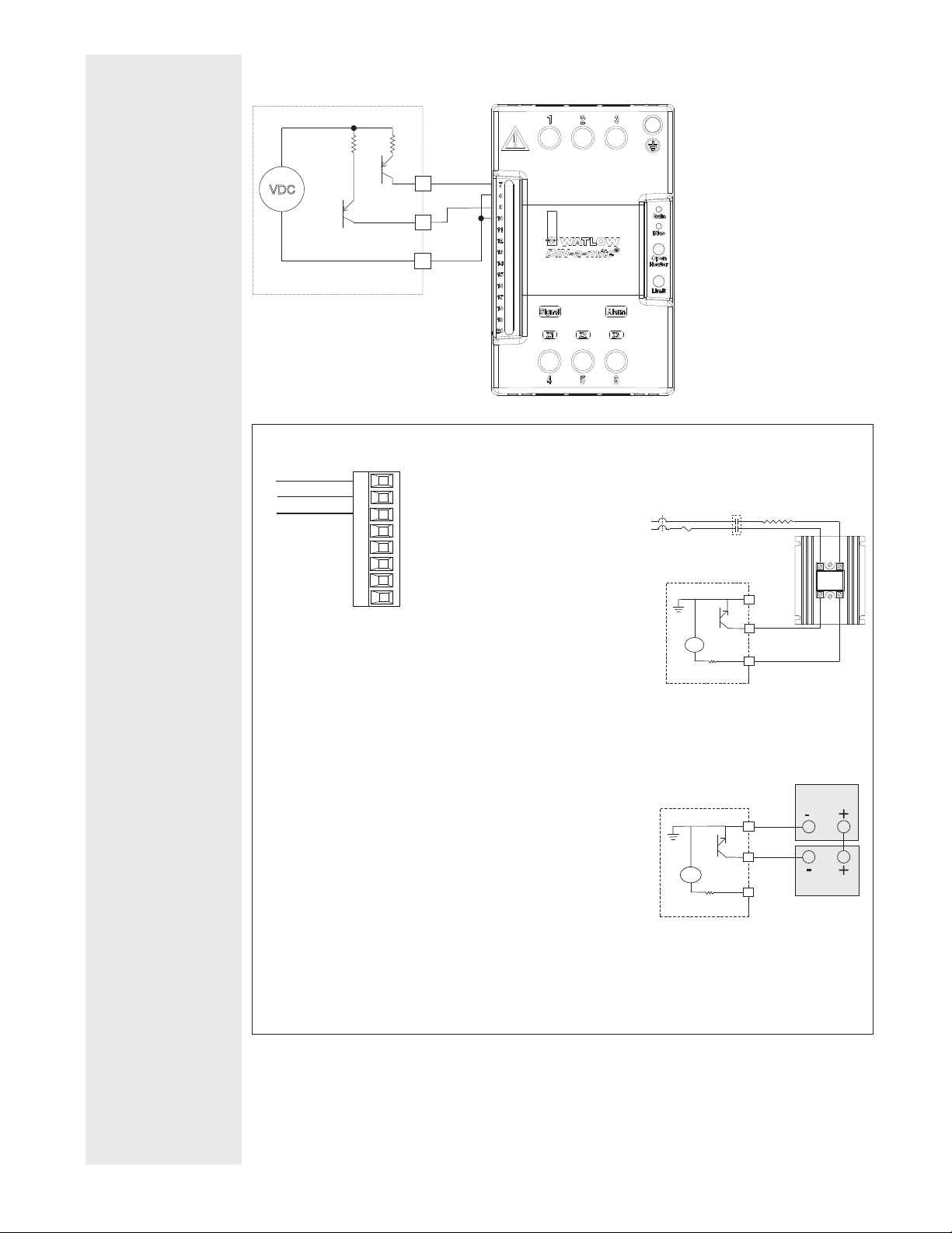
Switched DC Wiring Example Using DO 5-6
switched dc outputs
Htr 1
VDC
Internal Circuitry
Output 1, 3 Switched DC/Open Collector
common
dc - (open collector)
dc +
Slot A, B
X_
W_
Y_
D5
Htr 2
D6
B5
Switched DC
• Maximum open circuit voltage is
22 to 25VDC
• 30mA max. per single output /
40mA max. total per paired outputs
(1 & 2, 3 & 4)
• Typical drive; 4.5V (dc) @ 30mA
• Short circuit limited to <50mA
•
• NPN transistor sink
• Use dc- and dc+ to drive external
solid-state relay
• 1-pole DIN-A-MITE: up to 4 in
parallel or 4 in series
• 2-pole DIN-A-MITE: up to 2 in
parallel or 2 in series
• 3-pole DIN-A-MITE: up to 2 in
series
Open Collector
• 100mA maximum output current
sink
• 30V (dc) max. supply voltage
• Any switched dc output can use the
common terminal.
• Use an external power supply to
control a dc load, with the load
positive to the positive of the power
supply, the load negative to the
open collector and common to the
power supply negative.
+
-
+
-
DC80-60C0-0000
Switched DC
Contacts
(If Required)
X
W
Y
_
common
dc -
_
dc +
_
Heater
1(–) (+)2
4(–) (+)3
(-) (+)
L2
L1
Semiconductor
Fuse
Switched DC
24VDC
Open Collector
Power Supply
common
_
X
dc -
_
W
24VDC
_
Y
Output 1: (X1,-W1,+Y1)
PM _ _ _ [C] _ - _ _ _ _ _ _ _
Output 3: (X3,-W3,+Y3)
PM _ _ _ _ _ - _ _ [C] _ _ _ _
Load
Watlow PM PLUS™ 6 • 25 • Chapter 2: Installation
Page 26

Wiring Notes
Maximum wire size termination and torque rating:
0.0507 to 3.30 mm2 (30
to 12 AWG) single-wire
termination or two 1.31
mm2 (16 AWG)
0.56 Nm (5.0 in-lb.)
torque
Adjacent terminals may
be labeled differently
depending on the model
number.
Do not connect wires to
unused terminals.
Maintain electrical isolation between analog
input 1, digital inputoutputs, switched dc/
open collector outputs
and process outputs to
prevent ground loops.
This equipment is suitable for use in CLASS
I, DIVISION 2, Groups
A, B, C and D or NonHazardous locations only.
Temperature Code T4A
Wiring Warnings
ç
Use National Electric
(NEC) or other countryspecic standard wiring
and safety practices
when wiring this controller to a power source,
electrical sensors or peripheral devices. Failure
to do so may result in
damage to equipment
and property, and/or injury or loss of life.
Explosion Hazard - Dry
contact closure Digital
Inputs shall not be used
in Class I Division 2 Hazardous Locations unless
switch used is approved
for this application.
Explosion Hazard – Substitution of component
may impair suitability for
CLASS I, DIVISION 2.
Explosion Hazard - Do
not disconnect while the
circuit is live or unless
the area is known to be
free of ignitable concentrations of ammable
substances.
Output 1, 3 Mechanical Relay, Form C
Output 1: (L1,K1,J1 PM _ _ _ [E] _ - _ _ _ _ _ _ _
Output 3: (L3,K3,J3) PM _ _ _ _ _ - _ _ [E] _ _ _ _
normally open
common
normally closed
Slot A, B
L_
K_
J_
• 5A at 240VÅ (ac) or 30VÎ (dc) maximum resistive load
• 20mA at 24V minimum load
• 125VA pilot duty at 120/240VÅ (ac),
25VA at 24VÅ (ac)
• 100,000 cycles at rated load
• Output does not supply power.
• For use with ac or dc
Output 1, 3 Universal Process
Output 1: (F1,G1,H1) PM _ _ _ [F] _ - _ _ _ _ _ _ _
Output 3: (F3,G3,H3) PM _ _ _ _ _ - _ _ [F] _ _ _ _
volts or current -
volts +
current +
Slot A, B
F_
G_
H_
• 0 to 20mA into 800 Ω maximum
load
• 0 to 10VÎ (dc) into 1 kΩ minimum
load
• Scalable
• Output supplies power
• Cannot use voltage and current
outputs at same time
• Output may be used as retransmit
or control.
Output 1, 3 Solid-State Relay, Form A
Output 1: (L1, K1) PM _ _ _ [K] _ - _ _ _ _ _ _ _
Output 3: (L3, K3) PM _ _ _ _ _ - _ _ [K] _ _ _ _
Slot A, B
normally open
L_
common
K_
• 0.5A at 20 to 264VÅ (ac) max resistive
load
• 20VA 120/240VÅ (ac) pilot duty
• Opto-isolated, without contact suppression
• Maximum off state leakage of 105µA
• Output does not supply power
• Minimum holding current of 10mA
• Do not use on dc loads.
• See Quencharc note
4 to 20 mA
0 to 10 V
_
L
normally open
_
K
common
_
J
normally closed
3
F
negative
3
G
volts +
H3
current +
_
L
_
K
Watlow PM PLUS™ 6 • 26 • Chapter 2: Installation
Page 27
Wiring Notes
Maximum wire size
termination and torque
rating:
0.0507 to 3.30 mm2 (30
to 12 AWG) single-wire
termination or two 1.31
mm2 (16 AWG)
0.56 Nm (5.0 in-lb.)
torque
Adjacent terminals may
be labeled differently
depending on the model
number.
Do not connect wires to
unused terminals.
Maintain electrical isolation between analog
input 1, digital inputoutputs, switched dc/
open collector outputs
and process outputs to
prevent ground loops.
This equipment is suitable for use in CLASS I,
DIVISION 2, Groups A,
B, C and D or Non-Hazardous locations only.
Temperature Code T4A
Output 2, 4 Switched DC
Output 2: (-W2, +Y2) PM _ _ _ _ [C] - _ _ _ _ _ _ _
Output 4: (-W4, +Y4) PM _ _ _ _ _ - _ _ _ [C] _ _ _
dc-
dc+
Slot A, B
W_
Y_
• Maximum open circuit voltage 22 to 25VÎ (dc)
• 30mA max. per single output / 40mA max. total per paired outputs (1 & 2,
3 & 4)
• Typical drive; 4.5VÎ (dc) @ 30mA
• Short circuit limited to <50mA
• NPN transistor sink
• Use dc- and dc+ to drive external solid-state relay
• 1-pole DIN-A-MITE: up to 4 in parallel or 4 in series
• 2-pole DIN-A-MITE: up to 2 in parallel or 2 in series
• 3-pole DIN-A-MITE: up to 2 in series
Wiring Warnings
ç
Use National Electric
(NEC) or other countryspecic standard wiring
and safety practices
when wiring this controller to a power source,
electrical sensors or peripheral devices. Failure
to do so may result in
damage to equipment
and property, and/or injury or loss of life.
Explosion Hazard - Dry
contact closure Digital
Inputs shall not be used
in Class I Division 2 Hazardous Locations unless
switch used is approved
for this application.
Explosion Hazard – Substitution of component
may impair suitability for
CLASS I, DIVISION 2.
Explosion Hazard - Do
not disconnect while the
circuit is live or unless
the area is known to be
free of ignitable concentrations of ammable
substances.
Output 2, 4 NO-ARC Relay, Form A
Output 2: (L2, K2) PM _ _ _ _ [H] - _ _ _ _ _ _ _
Output 4: (L4, K4) PM [4, 8, 9] _ _ _ _ - _ _ _ [H] _ _ _
• 12A at 85 to 264VÅ (ac) resistive load only
• 2,000,000 cycle rating for NOARC circuit
• 100mA minimum load
• 2mA maximum off state leakage
• Do not use on dc loads
• Output does not supply power
normally open
common
Slot A, B
L_
K_
_
L
_
K
Watlow PM PLUS™ 6 • 27 • Chapter 2: Installation
Page 28
Wiring Notes
nor
Slot A, B
nor
Slot A, B
Maximum wire size termination and torque rating:
0.0507 to 3.30 mm2 (30
to 12 AWG) single-wire
termination or two 1.31
mm2 (16 AWG)
0.56 Nm (5.0 in-lb.)
torque
Adjacent terminals may
be labeled differently
depending on the model
number.
Do not connect wires to
unused terminals.
Maintain electrical isolation between analog
input 1, digital inputoutputs, switched dc/
open collector outputs
and process outputs to
prevent ground loops.
This equipment is suitable for use in CLASS
I, DIVISION 2, Groups
A, B, C and D or NonHazardous locations only.
Temperature Code T4A
Wiring Warnings
ç
Use National Electric
(NEC) or other countryspecic standard wiring
and safety practices
when wiring this controller to a power source,
electrical sensors or peripheral devices. Failure
to do so may result in
damage to equipment
and property, and/or injury or loss of life.
Explosion Hazard - Dry
contact closure Digital
Inputs shall not be used
in Class I Division 2 Hazardous Locations unless
switch used is approved
for this application.
Explosion Hazard – Substitution of component
may impair suitability for
CLASS I, DIVISION 2.
Explosion Hazard - Do
not disconnect while the
circuit is live or unless
the area is known to be
free of ignitable concentrations of ammable
substances.
Output 2, 4 Mechanical Relay, Form A
Output 2: (L2, K2) PM _ _ _ _ [J] - _ _ _ _ _ _ _
Output 4: (L4, K4) PM _ _ _ _ _ - _ _ _ [J] _ _ _
• 5A at 240VÅ (ac) or 30VÎ (dc) maximum
resistive load
• 20mA at 24V minimum load
• 125VA pilot duty @ 120/240VÅ (ac), 25VA
mally open
common
L_
K_
at 24VÅ (ac)
• 100,000 cycles at rated load
• Output does not supply power
• For use with ac or dc
• See Quencharc Wiring Example
Output 2, 4 Solid-State Relay, Form A
Output 2: (L2, K2) PM _ _ _ _ [K] - _ _ _ _ _ _ _
Output 4: (L4, K4) PM _ _ _ _ _ - _ _ _ [K] _ _ _
• 0.5A at 20 to 264VÅ (ac) maximum
resistive load
• 20VA 120/240VÅ (ac) pilot duty
• Opto-isolated, without contact sup-
mally open
common
L_
K_
pression
• Maximum off state leakage of 105µA
• Minimum holding current of 10mA
• Output does not supply power
• Do not use on dc loads.
• See Quencharc Wiring Example
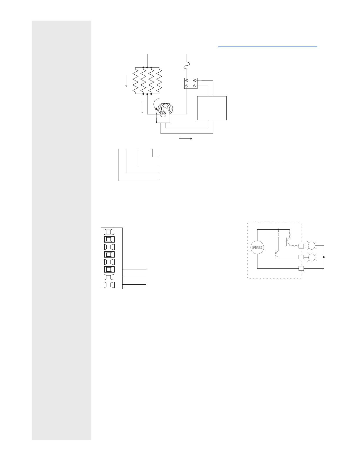
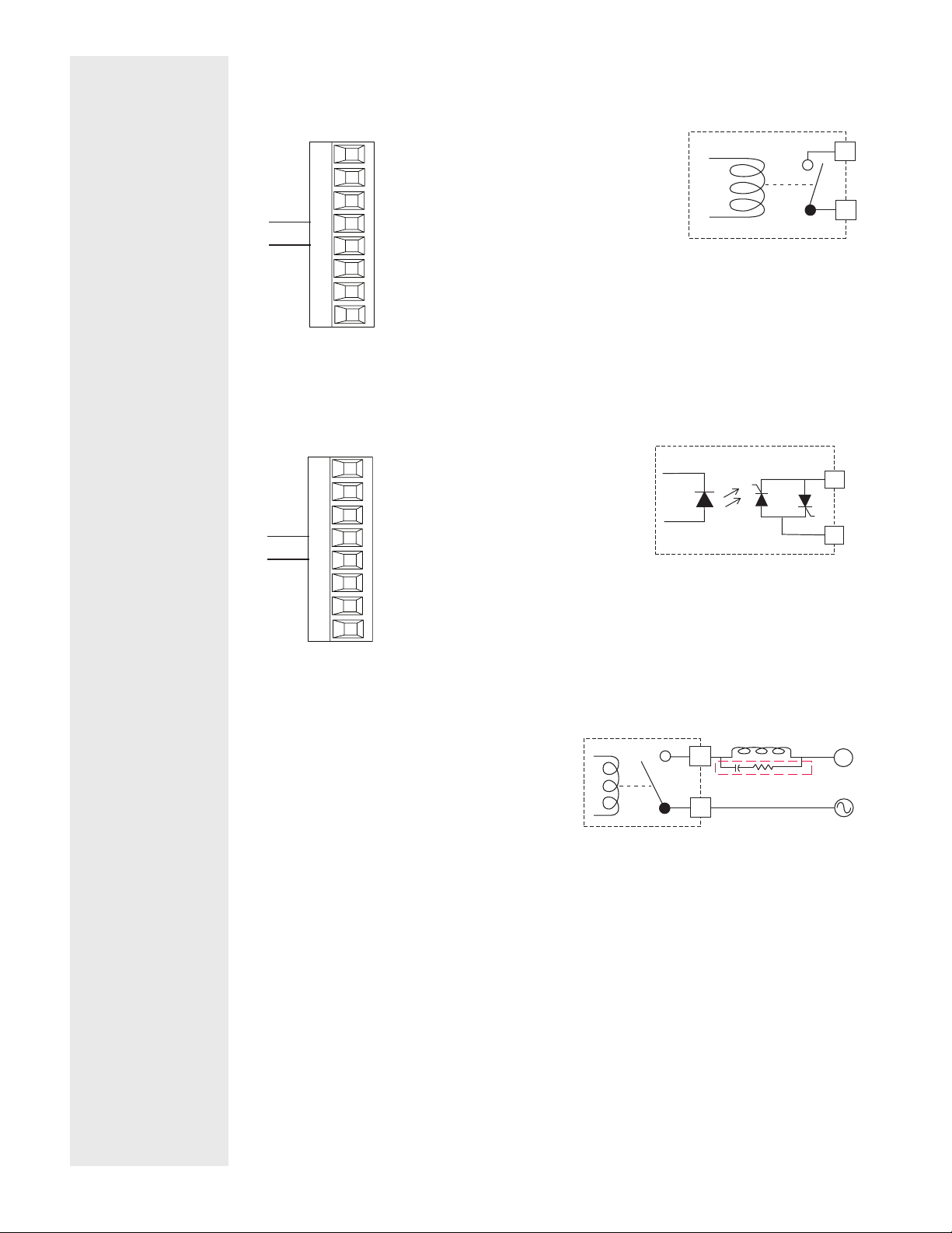
Quencharc Wiring Example
In this example the Quencharc circuit (Watlow part#
0804-0147-0000) is used to protect PM internal circuitry from the counter electromagnetic force from
the inductive user load when de-engergized. It is
recommended that this or an equivalent Quencharc
be used when connecting inductive loads to PM
outputs.
_
L
_
K
_
L
_
K
User Load
_
L
Quencharc
_
K
N
Watlow PM PLUS™ 6 • 28 • Chapter 2: Installation
Page 29

Wiring Notes
Maximum wire size
termination and torque
rating:
0.0507 to 3.30 mm2 (30
to 12 AWG) single-wire
termination or two 1.31
mm2 (16 AWG)
0.56 Nm (5.0 in-lb.)
torque
Adjacent terminals may
be labeled differently
depending on the model
number.
Do not connect wires to
unused terminals.
Maintain electrical isolation between analog
input 1, digital inputoutputs, switched dc/
open collector outputs
and process outputs to
prevent ground loops.
This equipment is suitable for use in CLASS I,
DIVISION 2, Groups A,
B, C and D or Non-Hazardous locations only.
Temperature Code T4A
Wiring Warnings
ç
Use National Electric
(NEC) or other countryspecic standard wiring
and safety practices
when wiring this controller to a power source,
electrical sensors or peripheral devices. Failure
to do so may result in
damage to equipment
and property, and/or injury or loss of life.
Explosion Hazard - Dry
contact closure Digital
Inputs shall not be used
in Class I Division 2 Hazardous Locations unless
switch used is approved
for this application.
Explosion Hazard – Substitution of component
may impair suitability for
CLASS I, DIVISION 2.
Explosion Hazard - Do
not disconnect while the
circuit is live or unless
the area is known to be
free of ignitable concentrations of ammable
substances.
Standard Bus EIA-485 Communications
PM _ _ _ _ _ - [*] _ _ _ _ _ _
*All models include Standard Bus communications (instance 1)
Slot C
98
99
CF
CD
CE
B5
D6
D5
common
T-/R-
T+/R+
• Wire T-/R- to the A terminal of the EIA-485 port.
• Wire T+/R+ to the B terminal of the EIA-485 port.
• Wire common to the common terminal of the EIA-485 port.
• Do not route network wires with power wires. Connect network wires in
daisy-chain fashion when connecting multiple devices in a network.
• Do not connect more than 16 controllers on a network.
• Maximum network length: 1,200 meters (4,000 feet)
• 1/8th unit load on EIA-485 bus
Note: Do not leave a USB to EIA-485 converter connected to Standard Bus without power (i.e., disconnecting the USB end from the PC and leave the converter
connected on Standard Bus). Disturbance on the Standard Bus may occur.
Modbus® RTU or Standard Bus EIA-485 Communications
PM _ _ _ _ - [1] _ _ _ _ _ _
Slot C
98
99
CC
CA
CB
B5
D6
D5
common
T-/R-
T+/R+
• Wire T-/R- to the A terminal of the EIA-485 port.
• Wire T+/R+ to the B terminal of the EIA-485 port.
• Wire common to the common terminal of the EIA-485 port.
• Do not route network wires with power wires. Connect network wires in
daisy-chain fashion when connecting multiple devices in a network.
• A termination resistor may be required. Place a 120 Ω resistor across T+/
R+ and T-/R- of last controller on network.
• Only one protocol per port is available at a time: either Modbus® RTU or
Standard Bus.
• Do not connect more than 16 controllers on a Standard Bus network.
• Maximum number of controllers on a Modbus® network is 247.
• Maximum network length: 1,200 meters (4,000 feet)
• 1/8th unit load on EIA-485 bus.
• Communications instance 1
Note: Do not leave a USB to EIA-485 converter connected to Standard Bus without power (i.e., disconnecting the USB end from the computer while leaving the
converter connected on Standard Bus). Disturbance on the Standard Bus may
occur.
Watlow PM PLUS™ 6 • 29 • Chapter 2: Installation
Page 30
Wiring Notes
Maximum wire size termination and torque rating:
0.0507 to 3.30 mm2 (30
to 12 AWG) single-wire
termination or two 1.31
mm2 (16 AWG)
0.56 Nm (5.0 in-lb.)
torque
Adjacent terminals may
be labeled differently
depending on the model
number.
Do not connect wires to
unused terminals.
Maintain electrical isolation between analog
input 1, digital inputoutputs, switched dc/
open collector outputs
and process outputs to
prevent ground loops.
This equipment is suitable for use in CLASS
I, DIVISION 2, Groups
A, B, C and D or NonHazardous locations only.
Temperature Code T4A
EIA-232/485 Modbus® RTU Communications
PM [6] _ _ _ _ - [2] _ _ _ _ _ _
485 T+/R+
485 T-/R-
485 common
485 T+/R+
485 T-/R-
232 common
232 (TX) to DB9 pin 2 (RD)
232 (RD) to DB9 pin 3 (TX)
Slot B, E
CB
CA
CC
CB
CA
C5
C3
C2
• Wire T-/R- to the A terminal of the EIA-485 port.
• Wire T+/R+ to the B terminal of the EIA-485 port.
• Wire common to the common terminal of the EIA-485 port.
• Do not route network wires with power wires. Connect network wires
in daisy-chain fashion when connecting multiple devices in a network.
• A termination resistor may be required. Place a 120 Ω resistor across
T+/R+ and T-/R- of last controller on network.
• Do not wire to both the EIA-485 and the EIA-232 pins at the same
time.
• Two EIA-485 terminals of T/R are provided to assist in daisy-chain
wiring.
• Do not connect more than one controller on an EIA-232 network.
• Maximum number of controllers on a Modbus® network is 247.
• Maximum EIA-232 network length: 15 meters (50 feet)
• Maximum EIA-485 network length: 1,200 meters (4,000 feet)
• 1/8th unit load on EIA-485 bus.
• Communications instance 2
Modbus®-
IDA Termi-
nal
EIA/TIA-485
Name
DO A CA or CD T-/RD1 B CB or CE T+/R+
common common CC or CF common
Watlow Ter-
minal Label
Function
Wiring Warnings
ç
Use National Electric
(NEC) or other countryspecic standard wiring
and safety practices
when wiring this controller to a power source,
electrical sensors or peripheral devices. Failure
to do so may result in
damage to equipment
and property, and/or injury or loss of life.
Explosion Hazard - Dry
contact closure Digital
Inputs shall not be used
in Class I Division 2 Hazardous Locations unless
switch used is approved
for this application.
Explosion Hazard – Substitution of component
may impair suitability for
CLASS I, DIVISION 2.
Explosion Hazard - Do
not disconnect while the
circuit is live or unless
the area is known to be
free of ignitable concentrations of ammable
substances.
EtherNet/IP™, PCCC, and Modbus® TCP Communications
(Instance 2)
Slot B: PM [6] _ _ _ _ - [3] _ _ _ _ _ _
unused
unused
receive -
unused
unused
receive +
transmit -
transmit +
Slot B, E
E8
E7
E6
E5
E4
E3
E2
E1
RJ-45 pin T568B wire color Signal Slot B
8 brown unused E8
7 brown & white unused E7
6 green receive - E6
5 white & blue unused E5
4 blue unused E4
3 white & green receive + E3
2 orange transmit - E2
1 white & orange transmit + E1
• Do not route network wires with power wires.
• Connect one Ethernet cable per controller to a 10/100 Mbps Ethernet
switch. Both Modbus® TCP and EtherNet/IP™ are available on the network.
• When using Modbus® TCP, the Network Status and Module Status LEDs
are not used.
Watlow PM PLUS™ 6 • 30 • Chapter 2: Installation
Page 31

Wiring Notes
Maximum wire size
termination and torque
rating:
0.0507 to 3.30 mm2 (30
to 12 AWG) single-wire
termination or two 1.31
mm2 (16 AWG)
0.56 Nm (5.0 in-lb.)
torque
Adjacent terminals may
be labeled differently
depending on the model
number.
Do not connect wires to
unused terminals.
Maintain electrical isolation between analog
input 1, digital inputoutputs, switched dc/
open collector outputs
and process outputs to
prevent ground loops.
This equipment is suitable for use in CLASS I,
DIVISION 2, Groups A,
B, C and D or Non-Hazardous locations only.
Temperature Code T4A
Wiring Warnings
Use National Electric
(NEC) or other countryspecic standard wiring
and safety practices
when wiring this controller to a power source,
electrical sensors or peripheral devices. Failure
to do so may result in
damage to equipment
and property, and/or injury or loss of life.
Explosion Hazard - Dry
contact closure Digital
Inputs shall not be used
in Class I Division 2 Hazardous Locations unless
switch used is approved
for this application.
Explosion Hazard – Substitution of component
may impair suitability for
CLASS I, DIVISION 2.
Explosion Hazard - Do
not disconnect while the
circuit is live or unless
the area is known to be
free of ignitable concentrations of ammable
substances.
ç
EtherNet/IP™, PCCC, and Modbus® TCP Communications
(Instance 2) continued
Note: When changing the fixed IP address cycle module power
for new address to take effect.
Ethernet LED Indicators
Viewing the control from the front and then looking on top four
LEDs can be seen aligned vertically front to back. The LEDs are
identified accordingly: closest to the front reflects the Network
(Net) Status, Module (Mod) Status is next, Activity status follows
and lastly, the LED closest to the rear of the control reflects the
Link status.
Note: When using Modbus TCP, the Network Status and
Module Status LEDs are not used.
Network Status Indicator (LED closest to the front)
Indicator
State
Steady Off Not powered,
Flashing Green No connections The device has no established connec-
Steady Green Connected The device has at least one established
Flashing Red Connection
Steady Red Duplicate IP The device detects that its IP address
Flashing Green
/ Red
Summary Requirement
The device does not have an IP ad-
no IP address
timeout
Self-test The device is performing its power up
dress (or is powered off).
tions, but has obtained an IP address.
connection (even to the Message
Router).
One or more connections in which this
device is the target timed out. This
clears only if all timed out connections
are reestablished or if the device is
reset.
is already in use.
testing,
Module Status Indicator (2nd from the front)
Indicator
State
Steady Off No power No power is supplied to the device.
Steady Green Operational The device is operating correctly.
Flashing Green Standby If the device has not been configured,
Flashing Red Minor fault The device detects a recoverable minor
Steady Red Major fault The device detects a non-recoverable
Flashing Green
/ Red
Summary Requirement
this LED flashes green.
fault. NOTE: An incorrect or inconsistent configuration is considered a
minor fault.
major fault.
Self-test While the device is performing power
up testing.
Activity Status Indicator (3rd from front)
Indicator
State
Flashing Green Detects activity MAC detects activity
Red - - - - MAC detects a collision.
Summary Requirement
Link Status Indicator (Last LED, near rear of the device)
Indicator
State
Steady Off Not powered,
Green - - - - Cable is wired and connected cor-
Summary Requirement
Device cannot determine link speed or
unknown link
speed
power is off.
rectly.
Watlow PM PLUS™ 6 • 31 • Chapter 2: Installation
Page 32

Wiring Notes
Maximum wire size termination and torque rating:
0.0507 to 3.30 mm2 (30
to 12 AWG) single-wire
termination or two 1.31
mm2 (16 AWG)
0.56 Nm (5.0 in-lb.)
torque
Adjacent terminals may
be labeled differently
depending on the model
number.
Do not connect wires to
unused terminals.
Maintain electrical isolation between analog
input 1, digital inputoutputs, switched dc/
open collector outputs
and process outputs to
prevent ground loops.
This equipment is suitable for use in CLASS
I, DIVISION 2, Groups
A, B, C and D or NonHazardous locations only.
Temperature Code T4A
DeviceNet™ Communications (Instance 2)
Slot B (PM [6] _ _ _ _ _ - [5] _ _ _ _ _ _ )
Terminal Signal Function
V+ V+ DeviceNet™ power
CH CAN_H positive side of DeviceNet™ bus
SH shield shield interconnect
CL CAN_L negative side of DeviceNet™ bus
V- V- DeviceNet™ power return
CAN_H
shield
CAN_L
V+
V+
CH
SH
CL
V-
T2
S2
R2
Slot B, E
V-
DeviceNet LED Indicators
Viewing the control from the front and then looking on top
two LEDs can be seen aligned vertically front to back. The
LED closest to the front is identified as the network (Net)
LED where the one next to it would be identified as the
module (Mod) LED.
Wiring Warnings
ç
Use National Electric
(NEC) or other countryspecic standard wiring
and safety practices
when wiring this controller to a power source,
electrical sensors or peripheral devices. Failure
to do so may result in
damage to equipment
and property, and/or injury or loss of life.
Explosion Hazard - Dry
contact closure Digital
Inputs shall not be used
in Class I Division 2 Hazardous Locations unless
switch used is approved
for this application.
Explosion Hazard – Substitution of component
may impair suitability for
CLASS I, DIVISION 2.
Explosion Hazard - Do
not disconnect while the
circuit is live or unless
the area is known to be
free of ignitable concentrations of ammable
substances.
Watlow PM PLUS™ 6 • 32 • Chapter 2: Installation
Page 33

Wiring Notes
Maximum wire size
termination and torque
rating:
0.0507 to 3.30 mm2 (30
to 12 AWG) single-wire
termination or two 1.31
mm2 (16 AWG)
0.56 Nm (5.0 in-lb.)
torque
Adjacent terminals may
be labeled differently
depending on the model
number.
Do not connect wires to
unused terminals.
Maintain electrical isolation between analog
input 1, digital inputoutputs, switched dc/
open collector outputs
and process outputs to
prevent ground loops.
This equipment is suitable for use in CLASS I,
DIVISION 2, Groups A,
B, C and D or Non-Hazardous locations only.
Temperature Code T4A
Wiring Warnings
Use National Electric
(NEC) or other countryspecic standard wiring
and safety practices
when wiring this controller to a power source,
electrical sensors or peripheral devices. Failure
to do so may result in
damage to equipment
and property, and/or injury or loss of life.
Explosion Hazard - Dry
contact closure Digital
Inputs shall not be used
in Class I Division 2 Hazardous Locations unless
switch used is approved
for this application.
Explosion Hazard – Substitution of component
may impair suitability for
CLASS I, DIVISION 2.
Explosion Hazard - Do
not disconnect while the
circuit is live or unless
the area is known to be
free of ignitable concentrations of ammable
substances.
ç
DeviceNet Network Status LED Indicator (LED closest to
the front of the device)
Indicator LED Description
The device is not online and has not completed the
Network
Status
(NS)
Off
Green
Red
Flashing Green
Flashing Red A poll connection has timed out.
duplicate MAC ID test yet. The device may not be
powered.
The device is online and has connections in the established state (allocated to a Master).
Failed communication device. The device has detected
an error that has rendered it incapable of communicating on the network (duplicate MAC ID or Bus-off).
The device is online, but no connection has been allocated or an explicit connection has timed out.
DeviceNet Module Status LED Indicator (Located next to the
Network Status LED)
Indicator
Module
Status
(MS)
LED
Off No power is applied to the device.
Flashing Green-
Red
Flashing Red Major Recoverable Fault.
Red Major Unrecoverable Fault.
Green The device is operating normally.
The device is performing a self-test.
J1939 CAN bus Communications (Instance 2)
Slot B (PM [6] _ _ _ _ _ - [7] _ _ _ _ _ _ )
CAN_L
CAN_H
Shield
Volts +
Volts -
Slot B, E
CL
CH
SH
V+
V-
Terminal Signal Function
CL CAN_L negative side of CAN bus
CH CAN_H positive side of CAN bus
SH shield shield interconnect
V+ V+ CAN bus power
V- V- CAN bus power return
J1939 LED Indicators
Viewing the control from the rear top, two LEDs are aligned vertically
front to back. The LED closest to the front is identified as CAN 2 (channel
2, currently not used) and the one closet to the connector is identified as
CAN 1 (channel 1).
CAN 1 Indicator
LED
Off
Flashing Red New CAN frame transmission occurred.
Flashing Green CAN communications active with J1939 Card.
CAN communications with J1939 Card inactive.
Description
Description
Watlow PM PLUS™ 6 • 33 • Chapter 2: Installation
Page 34

Wiring Notes
Maximum wire size termination and torque rating:
0.0507 to 3.30 mm2 (30
to 12 AWG) single-wire
termination or two 1.31
mm2 (16 AWG)
0.56 Nm (5.0 in-lb.)
torque
Adjacent terminals may
be labeled differently
depending on the model
number.
Do not connect wires to
unused terminals.
Maintain electrical isolation between analog
input 1, digital inputoutputs, switched dc/
open collector outputs
and process outputs to
prevent ground loops.
This equipment is suitable for use in CLASS
I, DIVISION 2, Groups
A, B, C and D or NonHazardous locations only.
Temperature Code T4A
Wiring Warnings
ç
Use National Electric
(NEC) or other countryspecic standard wiring
and safety practices
when wiring this controller to a power source,
electrical sensors or peripheral devices. Failure
to do so may result in
damage to equipment
and property, and/or injury or loss of life.
Explosion Hazard - Dry
contact closure Digital
Inputs shall not be used
in Class I Division 2 Hazardous Locations unless
switch used is approved
for this application.
Explosion Hazard – Substitution of component
may impair suitability for
CLASS I, DIVISION 2.
Explosion Hazard - Do
not disconnect while the
circuit is live or unless
the area is known to be
free of ignitable concentrations of ammable
substances.
Probus DP Communications
Slot B: PM [6] _ _ _ _-[6] _ _ _ _ _ _
+5Vdc Voltage Potential
485 T+/R+
485 T-/R-
Digital ground
Termination resistor B
485 T+/R+
485 T-/R-
Termination resistor A
Slot B & E
VP
B
A
DG
trB
B
A
trA
• Wire T-/R- to the A terminal of the EIA-485 port.
• Wire T+/R+ to the B terminal of the EIA-485 port.
• Wire Digital Ground to the common terminal of the EIA-485 port.
• Do not route network wires with power wires. Connect network wires
in daisy-chain fashion when connecting multiple devices.
• A termination resistor should be used if this is the last control on the
network.
• If using a 150 Ω cable Watlow provides internal termination. Place a
jumper across pins trB and B and trA and A.
• If external termination is to be used with a 150 Ω cable place a 390 Ω
resistor across pins VP and B, a 220 Ω resistor across pins B and A,
and lastly, place a 390 Ω resistor across pins DG and A.
• Do not connect more than 32 controllers on a segment.
• Maximum EIA-485 network length: 1,200 meters (4,000 feet)
• 1/8th unit load on EIA-485 bus
• When termination jumpers are in place, there is 392 ohm pull up
resistor to 5V and 392 ohm pull down resistor to DG. There is also a
221 ohm resistor between A and B.
• Communications instance 2
Profibus
Terminal
VP (Voltage
Potential)
EIA/TIA-485
Name
Watlow Ter-
minal Label
- - - - VP +5Vdc
Function
B-Line B B T+/R+
A-Line A A T-/R-
DP-GND common DG common
Profibus DP LED Indicators
Viewing the unit from the front and then looking on top of the controller two bi-color
LEDs can be seen where only the front one is used. Definition follows:
Indicator LED Description
Red Profibus network not detected
Red Flashing Indicates that the Profibus card is waiting for data exchange.
Green Data exchange mode
Watlow PM PLUS™ 6 • 34 • Chapter 2: Installation
Page 35

Wiring Notes
Maximum wire size
termination and torque
rating:
0.0507 to 3.30 mm2 (30
to 12 AWG) single-wire
termination or two 1.31
mm2 (16 AWG)
0.56 Nm (5.0 in-lb.)
torque
Adjacent terminals may
be labeled differently
depending on the model
number.
Do not connect wires to
unused terminals.
Maintain electrical isolation between analog
input 1, digital inputoutputs, switched dc/
open collector outputs
and process outputs to
prevent ground loops.
This equipment is suitable for use in CLASS I,
DIVISION 2, Groups A,
B, C and D or Non-Hazardous locations only.
Temperature Code T4A
Wiring a Serial EIA-485 Network
Do not route network wires with power wires. Connect network wires in daisy-chain
fashion when connecting multiple devices in a network. A termination resistor may
be required. Place a 120 Ω resistor across T+/R+ and T-/R- of the last controller on a
network.
Only one protocol per port is available at a time: either Modbus
®
RTU or Standard Bus.
Wiring Warnings
Use National Electric
(NEC) or other countryspecic standard wiring
and safety practices
when wiring this controller to a power source,
electrical sensors or peripheral devices. Failure
to do so may result in
damage to equipment
and property, and/or injury or loss of life.
Explosion Hazard - Dry
contact closure Digital
Inputs shall not be used
in Class I Division 2 Hazardous Locations unless
switch used is approved
for this application.
Explosion Hazard – Substitution of component
may impair suitability for
CLASS I, DIVISION 2.
Explosion Hazard - Do
not disconnect while the
circuit is live or unless
the area is known to be
free of ignitable concentrations of ammable
substances.
ç
Watlow PM PLUS™ 6 • 35 • Chapter 2: Installation
Page 36

Wiring Notes
Maximum wire size termination and torque rating:
0.0507 to 3.30 mm2 (30
to 12 AWG) single-wire
termination or two 1.31
mm2 (16 AWG)
0.56 Nm (5.0 in-lb.)
torque
Adjacent terminals may
be labeled differently
depending on the model
number.
Do not connect wires to
unused terminals.
Maintain electrical isolation between analog
input 1, digital inputoutputs, switched dc/
open collector outputs
and process outputs to
prevent ground loops.
This equipment is suitable for use in CLASS
I, DIVISION 2, Groups
A, B, C and D or NonHazardous locations only.
Temperature Code T4A
A Network of Devices Configured Using Modbus® RTU
Wiring Warnings
Use National Electric
(NEC) or other countryspecic standard wiring
and safety practices
when wiring this controller to a power source,
electrical sensors or peripheral devices. Failure
to do so may result in
damage to equipment
and property, and/or injury or loss of life.
Explosion Hazard - Dry
contact closure Digital
Inputs shall not be used
in Class I Division 2 Hazardous Locations unless
switch used is approved
for this application.
Explosion Hazard – Substitution of component
may impair suitability for
CLASS I, DIVISION 2.
Explosion Hazard - Do
not disconnect while the
circuit is live or unless
the area is known to be
free of ignitable concentrations of ammable
substances.
ç
Watlow PM PLUS™ 6 • 36 • Chapter 2: Installation
Page 37

Wiring Notes
Maximum wire size
termination and torque
rating:
0.0507 to 3.30 mm2 (30
to 12 AWG) single-wire
termination or two 1.31
mm2 (16 AWG)
0.56 Nm (5.0 in-lb.)
torque
Adjacent terminals may
be labeled differently
depending on the model
number.
Do not connect wires to
unused terminals.
Maintain electrical isolation between analog
input 1, digital inputoutputs, switched dc/
open collector outputs
and process outputs to
prevent ground loops.
This equipment is suitable for use in CLASS I,
DIVISION 2, Groups A,
B, C and D or Non-Hazardous locations only.
Temperature Code T4A
Connecting PM PLUS™ to a PC Using B&B 485 to USB Converter
Do not leave a USB to EIA-485 converter connected to Standard Bus without power (i.e., disconnecting the USB from the computer with the converter connected on Standard Bus).
If you connect a USB converter to your PC we recommend that you change
the Latency Timer from the default 16 msec to 1 msec. Go to Device Manager, double-click Port; right-click the USB serial port; select Properties;
click the Port Settings tab; click the Advanced button, then change the
Latency Timer to 1.
Failure to make this change may cause communication loss between the PC
running EZ-ZONE Configurator and the control.
Wiring Warnings
Use National Electric
(NEC) or other countryspecic standard wiring
and safety practices
when wiring this controller to a power source,
electrical sensors or peripheral devices. Failure
to do so may result in
damage to equipment
and property, and/or injury or loss of life.
Explosion Hazard - Dry
contact closure Digital
Inputs shall not be used
in Class I Division 2 Hazardous Locations unless
switch used is approved
for this application.
Explosion Hazard – Substitution of component
may impair suitability for
CLASS I, DIVISION 2.
Explosion Hazard - Do
not disconnect while the
circuit is live or unless
the area is known to be
free of ignitable concentrations of ammable
substances.
ç
Watlow PM PLUS™ 6 • 37 • Chapter 2: Installation
Page 38

Chapter 3: User Interface
Touch Keys
• Scroll up or down lists using the + or - keys.
• Increase or decrease numeric parameters, one increment at a time, with the + or - keys. Holding down the
+ or - key, will slew the setting at a faster rate, when the key is held down longer.
• Increase or decrease numeric parameters with the slider.
• Select items or move to lists using the forward/select arrow.
• Return to the previous screen with the back arrow.
• Return to the home screen from any other screen by pressing the Home icon.
• Change the set point directly from the home screen using the numeric slider or the + or - keys
• The function key can be programmed to do various tasks like starting a profile.
Home Screen
The home screen provides a shortcut to monitor or change the parameter values that you use most often.
When a parameter from the Setup List or Operations List is displayed on the Home Screen, you can adjust that
parameter's value in either place, using the numeric slider or +/- keys on the front of the device.
Default Home Screen Parameters
By default, the home screen display shows the Process Value, the Set Point, and the Zone being read. The
upper display is the process value, or the value of the parameter indicated in the lower display. The lower display shows the set point or manual power value, or the parameter for the value showing in the upper display.
Watlow PM PLUS™ 6 • 38 • Chapter 3: User Interface
Page 39

If Control Mode is Auto, the Process Value and Set Point (read-write) are displayed.
If a profile is running, the Process Value and Target Set Point (read only) are displayed.
If Control Mode is Manual, Process Value and Output Power Level (read-write) are displayed.
If Control Mode is set to Off, the Process Value is displayed with off (read only).
If a sensor failure has occurred, dashes ---- are displayed with the Manual Power (read-write).
Active Messages on the Home Screen
An active message will display on the front of the device and toggle between the normal Home Screen display
and the active message. Some messages indicate an error, and some are simply informational and indicate
that a process is underway.
Alarm Low 1 to 4
Alarm High 1 to 4
Alarm Error 1 to 4
Error Input 1 or 2
Limit Low 1
Limit High 1
Limit Error 1
Tuning 1
Ramping 1
. Loop Open Error 1
Loop Reversed Error 1
Current Error
Heater Error
Value to high to be displayed in 4 digit LED display >9999
Value to low to be displayed in 4 digit LED display <-1999
Responding to Active Messages
If the message was generated by a latched alarm or limit condition, the message can be cleared only when the
condition no longer exists. Press the forward arrow to display Ignore and the message source (such as Limit
High). Use the slider or the +/- keys to scroll through possible responses, such as Clear or Silence, then push
the forward arrow key to execute the action.
Home Screen Themes
You may select another home screen theme to see a different color format and/or to see the output percentage
in addition to process value and set point.
1.
Operations — Setup — Global — Home Screen
2. Select the preferred theme:
• 0 (Default) = Black background; colored letters
• 1 = White background; colored letters
• 2 = Black background; red/green/orange letters; includes output power percentage display next
to set point
• 3 (High Contrast) = Blue background; white letters; includes output power percentage display next
to set point
Watlow PM PLUS™ 6 • 39 • Chapter 3: User Interface
Page 40

Chapter 4: Operations
All parameters and lists of options are accessed via the Operations List.
Parameters directly in the Operations List are generally used for operations and monitoring. (Additional
parameters are located in the Setup, Factory, Profile, and Global Lists, which you can access via
Operations). The Operations List includes:
• Default parameters/sublists that vary depending on the features enabled on your device, as indicated on
the configuration code.
• Custom parameters that you have added via Operations — Factory — Custom Setup (See "Adding
Custom Parameters to the Operations List.")
• Setup List
• Profile Status and Profile Lists (if enabled on your device)
• Factory List
If you choose to use Modbus
®
or another communication protocol to write to the PM PLUS, you will need
the parameter IDs. For details about fieldbus addresses and Data Types, refer to the "EZ-ZONE All Register
List."
Operations List
Default Operations Parameters/Sublists
The default parameters in the Operations List vary on every PM PLUS. This list is populated with
parameters applicable to the features enabled on the device and the settings chosen in
— Setup. (Refer to the configuration code on the device's product label).
Parameter Description Range Default ID
Control Mode
Active
Heat Power View the current heat output level. 0.0 to 100.0% - - - Cool Power View the current cool output level. -100.0 to 0.0% - - - Autotune Start an autotune. While active, "Autotune"
View the current control mode. Off (62)
Auto (10)
Manual (54)
Yes (106)
displays on the Home Screen.
No (59)
Operations
- - - -
No 8026
8002
8011
8014
Timer Functions
These appear in the Operations List on devices with T in the 4th digit, for timer enabled models
Ready Band State Display whether the process value is in the
ready band.
Ready Band Set how close the process value must be to
the closed loop timer set point to be in the
ready band.
Closed Loop
Timer Set Point
Hours Set the timer period hours. 0 to 99 0 31025
Minutes Set the timer period minutes. 0 to 59 0 31026
Watlow PM PLUS™ 6 • 40 • Chapter 4: Operations
The set point that will be in effect during
the timer period
Yes (106)
No (59)
0.000 to 9999.000°F or units
0.000 to 5555.000°C
-1999.000 to 9999.000°F or units
-1110.555 to 5555.000°C
- - - - 31022
5
75 31028
31023
Page 41

Default Operations Parameters/Sublists
The default parameters in the Operations List vary on every PM PLUS. This list is populated with
parameters applicable to the features enabled on the device and the settings chosen in
Operations
— Setup. (Refer to the configuration code on the device's product label).
Parameter Description Range Default ID
Seconds Set the timer period seconds. 0 to 59 10 31027
Special Output Function
These appear in Operations on devices with a V in the 12th digit of the configuration code.
Source Value A Special Output Function (1)
View the value of Source A.
Source Value B Special Output Function (1)
View the value of Source B.
Output Value 1 Special Output Function (1)
View the value of this function's Output 1.
Output Value 2 Special Output Function (1)
View the value of this function's Output 2.
-1,999.000 to 9,999.000°F or units
-1,128.000 to 5,537.000°C
-1,999.000 to 9,999.000°F or units
-1,128.000 to 5,537.000°C
-1,999.000 to 9,999.000°F or units
-1,128.000 to 5,537.000°C
-1,999.000 to 9,999.000°F or units
-1,128.000 to 5,537.000°C
- - - -
- - - -
- - - -
- - - -
35007
35008
35010
35012
Profile Functions
These appear in Operations on devices with N or R in the 4th digit of the configuration code.
See Operations - Setup - for a full list of configurable parameters for this functionality
Profile Start Starts the profile 1 to 40 1 22001
Profile Action
Request
Profile Status Currently running step in the profile 1 to 40 ---- 22004
Requests any of the range of actions None (61)
Step (89)
End (148)
Resume (147)
Pause (146)
Profile (77)
None 22011
Watlow PM PLUS™ 6 • 41 • Chapter 4: Operations
Page 42

Adding Custom Parameters to the Operations List
Up to 20 custom parameters can be added to the Operations List. The parameters available for selection vary
depending on the configuration code of your device. Refer to your product label for the configuration code.
1. Navigate to:
Operations — Factory — Custom Setup — Custom Setup [1-20] — Parameter
2. Scroll to and select the parameter to display. Refer to table: "Operations List - Custom Parameter Options."
Operations List - Custom Parameter Options
All Models
Analog Input Value (Instances 1 or 2)
Cal In Offset (Instances 1 or 2)
Display Units
Load Parameter Set (Instances 1 or 2)
Alarm Low Set Point (Instances 1, 2, 3, or 4)
Alarm High Set Point (Instances 1,2, 3, or 4)
Alarm Hysteresis (Instances 1, 2, 3, or 4)
Additional Parameters Available if 4th digit of configuration code is T
Time Remaining
Ready Band State
Ready Band
Closed Loop Timer Set Point
Hours
Minutes
Seconds
Additional Parameters Available if 4th or 9th digit of configuration code is L or M
Limit Set Point Low
Limit Set Point High
Limit Hysteresis
Limit Status
Additional Parameters Available if 4th digit of configuration code is B, E, C, R, J, or N
Set Point (Instances 1 or 2)
Active Process Value (Instances 1 or 2)
Active Set Point (Instances 1 or 2)
Manual Power (Instances 1 or 2)
Autotune (Instances 1 or 2)
Control Mode (Instances 1 or 2)
Heat Power (Instances 1 or 2)
Cool Power (Instances 1 or 2)
Time Integral (Instances 1 or 2)
Time Derivative (Instances 1 or 2)
Watlow PM PLUS™ 6 • 42 • Chapter 4: Operations
Page 43

Dead Band (Instances 1 or 2)
Heat Prop Band (Instances 1 or 2)
On/Off Heat Hysteresis (Instances 1 or 2)
Cool Prop Band (Instances 1 or 2)
On/Off Cool Hysteresis (Instances 1 or 2)
Ramp Rate (Instances 1 or 2)
TRU-TUNE+ Enable (Instances 1 or 2)
Idle Set Point (Instances 1 or 2)
Additional Parameters Available if 4th digit of configuration code is B, E, R or N
Profile Start
Profile Action Request
Current Step
Step Type
Target Set Point (Instances 1 or 2)
Hour
Minute
Second
Guaranteed Soak Deviation 1
Additional Parameters Available if 9th digit of configuration code is T
Load Current RMS
Watlow PM PLUS™ 6 • 43 • Chapter 4: Operations
Page 44

Chapter 5: Setup
Default Configurations for Quick Start
If you are using the default input type, you can simply connect your input and output devices to the control,
then power up the control and press the slider or the +/- keys on the front of the control to change the set
point from the default value (75°F) to the desired value. As the Set Point increases above the Process Value,
output 1 will come on and begin driving the output device.
Parameter Default Setting To Edit
Analog Input Thermocouple, type J Operations — Setup — Analog Input — Sensor Type
Function Heat Operations — Setup — Output — Output 1 — Function
Heat Algorithm PID, cool set to "off" Operations — Setup — Control Loop — Heat Algorithm
Set Point 75° Press the numeric slider or +/- keys on the front panel
Control Mode Auto Operations — Control Mode
Configuring Parameters
1. Press the right arrow key to open the Operations List, then navigate to the parameter following the breadcrumbs indicated, i.e.
the right arrow key to select the highlighted parameter.
2. Use the numeric slider or +/- keys to either highlight or enter the desired option/setting for the parameter,
3. Press the home, left or right arrow key to select the option highlighted/entered.
4. Press the left back arrow to return to the previous List, or press the Home icon to exit all Lists and return
to the home screen.
Operations — Setup — Analog Input — Sensor Type.
Use the +/- keys to scroll and
Using Watlow Software to Configure Parameters
You can set up all parameters directly from the PM PLUS™ front panel via the Setup List, as explained
in this manual, or use Watlow CONFIGURATOR or COMPOSER on a PC. If you choose to use Watlow
CONFIGURATOR or COMPOSER software to set up the PM PLUS™ from your PC, you'll need to wire
communications (see Chapter 2). There are two ports (instances) for communications. Port 1 is dedicated
to Standard Bus communications. Port 1 may also be used for Modbus
used with Modbus
You will need the parameter IDs listed in the table: "Setup Lists" if you use Modbus
nication protocol to write to the PM PLUS™ from a configuration software. For detailed information about
Modbus
Watlow website.
®
, CIP or Profibus addresses, and Data Types, refer to the "EZ-ZONE All Register List." on the
®
, DeviceNet, Ethernet/IP, J1939 CAN, or Profibus.
®
RTU if purchased. Port 2 may be
®
or another commu-
Range selections can be made by writing the enumerated value of choice using any of the available communications protocols. For example, to turn an analog input sensor off (as seen at Operations — Setup — Ana-
log Input — Sensor Type) using Modbus
control. For complete instructions, refer to that software's user manual available on Watlow.com.
Watlow PM PLUS™ 6 • 44 • Chapter 5: Setup
®
, write the value 62 (off) to register 368 and send that value to the
Page 45

Setup List
Setup Lists
You will not see every parameter listed here. These vary depending on the features enabled on your device.
Analog Input List
Operations — Setup — Analog Input
Parameter Description Range of Options Default ID*
Analog Input [1,2] The process value of the input. Select instance
1 or 2 if there are two input instances. (Without two analog input instances, Analog 1 will
be automatically selected/displayed and Analog
2 will not appear).
Note: Ensure that there is no Input Error (61)
when reading this value using a field bus protocol. If an error exists, the last known value prior
to the error will be returned.
Operations — Setup — Analog Input — [Analog Input 1, Analog Input 2]
-1,999.000 to 9,999.000°F
or units
-1,128.000 to 5,537.000°C
- - - - 4001
Sensor Type Analog sensor type wired to this input.
Note: There is no open sensor protection for
process inputs.
TC Linearization Thermocouple linearization wired to this input.
RTD Leads Quantity of leads on the RTD wired to this
input.
Off (62)
Thermocouple (95)
Millivolts (56)
Volts dc (104)
Milliamps dc (112)
RTD 100 Ω (113)
RTD 1,000 Ω (114)
Potentiometer 1 kΩ (155)
Thermistor (229)
B (11)
K (48)
C (15)
N (58)
D (23)
R (80)
E (26)
S (84)
F (30)
T (93)
J (46)
2 (1)
3 (2)
Thermocouple
or Thermistor
J 4006
2 4007
4005
Watlow PM PLUS™ 6 • 45 • Chapter 5: Setup
Page 46

Setup Lists
You will not see every parameter listed here. These vary depending on the features enabled on your device.
Units Type of units the sensor measures. Absolute Temperature
(1540)
Relative Humidity (1538)
Process (75)
Power (73)
Scale Low Low scale for process inputs. This value, in
millivolts, volts or milliamps, corresponds to
the Range Low output
Scale High High scale for process inputs. This value in
millivolts, volts or milliamperes corresponds to
the Range High output of this function block.
Range Low Set the low range for this function block's
output.
Range High Set the high range for this function block's
output.
Process Error Enable Turn the Process Error Low feature on or off. Off (62)
Proc.Error Low Value If the process value drops below this value, it
will trigger an input error.
Thermistor Curve Select a curve to apply to the thermistor input. Curve A (1451)
-100.00 to 1,000.00 0. 0 4015
-100.00 to 1,000.00 20.0 4016
-1,999.000 to 9,999.000 0.0 4017
-1,999.000 to 9,999.000 9,999 4018
Low (53)
-100.00 to 1,000.00 0.0 4031
Curve B (1452)
Curve C (1453)
Custom (180)
Process 4042
Off 4030
Curve A 4038
Resistance Range Set the maximum resistance of the thermistor
input.
Filter Filtering smooths out the process signal to
both the display and the input. Increase the
time to increase filtering.
Note: Filter does not apply to the Limit sensor
but does apply to all other functions.
Input Error Latching Turn input error latching on or off. If latching
is on, errors must be manually cleared.
Display Precision Set the precision of the displayed value. Whole (105)
Calibration Offset Offset the input reading to compensate for lead
wire resistance or other factors that cause the
input reading to vary from the process value.
Analog Input Value View the process value. Ensure that the Error
Status is no error (61) when reading this value
using a field bus protocol. If an error exists,
the last known value prior to the error will be
returned.
5K (1448)
10K (1360)
20K (1361)
40K (1449)
0.0 to 60.0 seconds 0.5 4014
Off (62)
On (63)
Tenths (94)
Hundredths (40)
Thousandths (96)
-1,999.000 to 9,999.000°F
or units
-1,110.555 to 5,555.000°C
-1,999.000 to 9,999.000°F
or units
-1,128.000 to 5,537.000°C
40K 4037
Off 4028
Whole 4020
0.0 4012
- - - - 4001
Watlow PM PLUS™ 6 • 46 • Chapter 5: Setup
Page 47

Setup Lists
You will not see every parameter listed here. These vary depending on the features enabled on your device.
Input Error View the cause of the most recent error. None (61)
Open (65)
Shorted (127)
Measurement Error (140)
Bad Calibration Data (139)
Ambient Error (9)
RTD Error (141)
Fail (32)
- - - - 4002
Digital Bus List
Operations — Setup — Digital Bus (J1939 CAN) —
J1939 Instance Select the instance. 1 to 6 - - - - - - - -
Operations — Setup — Digital Bus (J1939 CAN) — [Digital Bus 1,2,3,4,5,6] —
Units Set the type of units the sensor will measure. Absolute Temperature
(1540)
Relative Temperature
(1541)
Power (73)
Process (75)
Relative Humidity (1538)
None (61)
Input Value View the input value. -1,999.000 to 9,999.000 - - - - 95001
Input Error Selected sensor instance is in error state. None (61)
Open (65)
Shorted (127)
Measurement Error (140)
Bad Calibration Data (139)
Ambient Error (9)
RTD Error (141)
Fail (32)
Math Error (1423)
Not Sourced (246)
Stale (883)
Output Value View the output value of Digital Bus 1-6. -1,999.000 to 9,999.000 - - - - 95003
CAN ID High Word Digital Bus (1 to 4) 0 to 65,535 0 94023
Absolute Temperature
Stale 95002
95005
CAN ID Low Word Digital Bus (1 to 4) 0 to 65,535 0 94022
Encoding Typ Digital Bus (1 to 6) State (2008)
Slots (2009)
Start Byte Digital Bus (1 to 4) 1 to 8 1.0 94006
Start Bit Digital Bus (1 to 4) 1 to 8 1.0
Signal Length in Bits Digital Bus (1 to 4) 1 to 63 1.0
Scaling Numerator Digital Bus (1 to 4) 1 to 65,535 Instance
Scaling Denominator Digital Bus (1 to 4) 1 to 65,535 Instance
Slots 94005
94007
94008
- - - 1,2,3,6 = 128,
Instance 4,5
= 1
- - - 1,2,3,6 =
4096, Instance
4, 5 = 1
Watlow PM PLUS™ 6 • 47 • Chapter 5: Setup
Page 48

Setup Lists
You will not see every parameter listed here. These vary depending on the features enabled on your device.
Offset Digital Bus (1 to 4) -1,999.000 to 9,999.000 1.0 93010
Filter Digital Bus (1 to 4) -1,999.000 to 9,999.000 1.0 93011
CAN Units Digital Bus (1 to 6) °F (30)
°C (15)
None
Output Error Output Error None (61)
Open (65)
Shorted (127)
Measurement Error (140)
Bad Calibration Data (139)
Ambient Error (9)
RTD Error (141)
Fail (32)
Math Error (1423)
Not Sourced (246)
Stale (883)
Action Function Select the function that will be triggered by a
true state for Digital Inputs 5 or 6.
None (61)
Start Step (1077)
Profile Start/Stop, level triggered (208)
Start Profile, edge triggered
(196)
Profile Hold/Resume, level
triggered (207)
Profile Disable, level triggered (206)
TRU-TUNE+ Disable, level
triggered (219)
Switch Control Loop Off,
level triggered (90)
Manual, level triggered (54)
Tune, edge triggered (98)
Idle Set Point, level triggered (107)
Force Alarm, level triggered
(218)
Control Loops Off and
Alarms to Non-alarm State,
level triggered (220)
Silence Alarms, edge triggered (108)
Alarm Reset, edge triggered
(6)
Keypad Lockout, level triggered (217)
User Set Restore, edge triggered (227)
Remote Set Point (216)
Instance 5 =
None, instance
1,2,3,4, 6 = C
Stale 95004
None 10003
93021
Function Instance Select which Digital Input will be triggered by
a true state.
0 to 40 0 10004
Watlow PM PLUS™ 6 • 48 • Chapter 5: Setup
Page 49

Setup Lists
You will not see every parameter listed here. These vary depending on the features enabled on your device.
Linearization List
Operations — Setup — Linearization — [Linearization 1, Linearization 2] —
Function Set how this function will linearize Source A. Off (62)
Interpolated (1482)
Source Function A Set the source for the Linearization function.
Note: Instance 2 applies if configuration code
digit 8 = 7 or K and digit 9 = C, J, R or P.
Source Instance A Set the instance of the function.
Note: Instance 2 applies if configuration code
digit 8 = 7 or K and digit 9 is C, J, R or P.
Units Set the units of the output value. Source (1539)
Input Point 1 The value that will be mapped to output 1. -1,999.000 to 9,999.000 0.0 34008
Output Point 1 The value that will be mapped to input 1. -1,999.000 to 9,999.000 0.0 34018
Input Point 2 The value that will be mapped to output 2. -1,999.000 to 9,999.000 1.0 34009
Output Point 2 The value that will be mapped to input 2. -1,999.000 to 9,999.000 1.0 34019
Input Point 3 The value that will be mapped to output 3. -1,999.000 to 9,999.000 2.0 34010
Analog Input (142)
Digital Bus Input (1993)
1 to 8 34002
None (61)
Absolute Temperature
(1540)
Relative Temperature
(1541)
Power (73)
Process (75)
Relative Humidity (1538)
Off 34005
34001
Source 34029
Output Point 3 The value that will be mapped to input 3. -1,999.000 to 9,999.000 2.0 34020
Input Point 4 The value that will be mapped to output 4. -1,999.000 to 9,999.000 3.0 34011
Output Point 4 The value that will be mapped to input 4. -1,999.000 to 9,999.000 3.0 34021
Input Point 5
Output Point 5
Input Point 6
Output Point 6
Input Point 7
Output Point 7
Input Point 8
Set the value mapped to output 5.
Set the value mapped to input 5.
Set the value mapped to output 6.
Set the value mapped to input 6. -1,999.000 to 9,999.000 5.0 34023
Set the value mapped to output 7. -1,999.000 to 9,999.000 6.0 34014
Set the value mapped to input 7. -1,999.000 to 9,999.000 6.0 34024
Set the value mapped to output 8. -1,999.000 to 9,999.000 7.0 34015
-1,999.000 to 9,999.000 4.0 34012
-1,999.000 to 9,999.000 4.0 34022
-1,999.000 to 9,999.000 5.0 34013
Watlow PM PLUS™ 6 • 49 • Chapter 5: Setup
Page 50

Setup Lists
You will not see every parameter listed here. These vary depending on the features enabled on your device.
Output Point 8 Set the value mapped to input 8. -1,999.000 to 9,999.000 7.0 34025
Input Point 9 Set the value mapped to output 9. -1,999.000 to 9,999.000 8.0 34016
Output Point 9 Set the value mapped to input 9. -1,999.000 to 9,999.000 8.0 34026
Input Point 10 Set the value mapped to output 10. -1,999.000 to 9,999.000 9.0 34017
Output Point 10 Set the value mapped to input 10. -1,999.000 to 9,999.000 9.0 34027
Process Value List
Operations — Setup — Process Value — [Process Value 1, Process Value 2] —
Function Set the function that will be applied to the
source or sources.
Note: Differential and Ratio not available using
instance 2.
Pressure Units*** If Process Value function is set for Pressure
to Altitude units, define units of measure for
conversion.
Altitude Units*** If Process Value function is set for Pressure
to Altitude units, define units of measure for
conversion.
Barometric Pressure*** If Process Value function is set for Wet Bulb
/ Dry Bulb, define pressure value used for humidity calculation.
Filter Filtering smooths out the output signal of this
function block. Increase the time to increase
filtering.
Off (62)
Pressure to Altitude
(1649)***
Square Root (1380)
Differential (1373)
Ratio (1374)
Wet Bulb Dry Bulb (1369)
Vaisala (1648)
Sensor Backup (1201)
Pounds per Square Inch
(1671)
Pascal (1674)
Atmosphere (1675)
Millibar (1672)
Torr (1673)
Kilofeet (1677)
Feet (1676)
10.0 to 16.0 14.7 26030
0.0 to 60.0 seconds 0.0 26026
Off 26021
PSI 26028
HFt 26029
*** Pressure Altitude calculation is based on the International Standard Atmosphere 1976
Source Value A The value of Source A. Linearization 1 is con-
nected to Source A of Process Value 1. Linearization 2 is connected to Source A of Process
Value 2
Source Value B View the value of Source B. Linearization 2 is
connected to Source B of Process Value 1.
Linearization 1 is connected to Source B of
Process Value 2
Offset The offset to be applied to this function's out-
put.
Output Value View the value of this function block's output. -1,999.000 to 9,999.000°F
-1,999.000 to 9,999.000°F
or units
-1,128.000 to 5,537.000°C
-1,999.000 to 9,999.000°F
or units
-1,128.000 to 5,537.000°C
-1,999.000 to 9,999.000°F
or units
-1,128.000 to 5,537.000°C
or units
-1,128.000 to 5,537.000°C
- - - - 26016
- - - - 26017
0 26023
- - - - 26022
Watlow PM PLUS™ 6 • 50 • Chapter 5: Setup
Page 51

Setup Lists
You will not see every parameter listed here. These vary depending on the features enabled on your device.
Digital Input/Output List
Operations — Setup — Digital I/O — [Digital I/O 5, Digital I/O 6] —
Direction Set this function to operate as an input or
output.
Function Select what function will drive this output. Off (62)
Output Function
Instance
Time Base Type Set the time base type. This parameter is only
Fixed Time Base Set the time base for fixed-time-base control. 0.1 to 60.0 seconds 1.0 6003
Low Power Scale The power output will never be less than the
High Power Scale The power output will never be greater than
Active Level Select which action will be interpreted as a
Set the instance of the function selected. 1 to 4 1 6006
used with PID control, but can be set anytime.
value specified and will represent the value at
which output scaling begins.
the value specified and will represent the value
at which output scaling stops.
true state.
Output (68)
Input Voltage (193)
Input Dry Contact (44)
Alarm (6)
Heat (36)
Cool (20)
Heater Error (184)
Fixed Time Base (34)
Variable Time Base (103)
0.0 to 100.0% 0.0 6009
0.0 to 100.0% 100.0 6010
High (37)
Low (53)
Output 6001
Off 6005
Fixed Time
Base
High 10001
6002
Watlow PM PLUS™ 6 • 51 • Chapter 5: Setup
Page 52

Setup Lists
You will not see every parameter listed here. These vary depending on the features enabled on your device.
Active Function Select the function that will be triggered by a
true state for Digital Inputs 5 to 6.
None (61)
User Set Restore, edge
triggered (227)
Keypad Lockout, level
triggered (217)
Alarm Reset, edge
triggered (6)
Silence Alarms, edge
triggered (108)
Start Step, edge triggered
(1077)
Profile Start/Stop, level
triggered (208)
Start Profile, edge triggered
(196)
Profile Hold/Resume, level
triggered (207)
Profile Disable, level
triggered (206)
Control Loops Off and
Alarms to Non-alarm State,
level triggered (220)
Remote Set Point, level
triggered (216)
Force Alarm to occur, level
triggered (218)
Idle Set Point, level
triggered (107)
Tune, edge triggered (98)
Manual, level triggered (54)
Switch Control Loop Off,
level triggered (90)
TRU-TUNE+ Disable, level
triggered (219)
None 10003
Function Instance Select which Digital Input will be triggered
by a true state.
0 to 40 0 10004
Limit List
Operations — Setup — Limit —
Sides Select the side or sides of the process value to
be monitored.
Watlow PM PLUS™ 6 • 52 • Chapter 5: Setup
Both (13)
High (37)
Low (53)
Both 12005
Page 53

Setup Lists
You will not see every parameter listed here. These vary depending on the features enabled on your device.
Hysteresis
Maximum Set Point Set the high end of the limit set point range. -1,999.000 to 9,999.000 9,999.000 12009
Minimum Set Point Set the low end of the limit set point range. -1,999.000 to 9,999.000 -1,999.000 12010
High Limit Set Point * Set the high process value that will trigger the
Low Limit Set Point * Set the low process value that will trigger the
Source Function A * Set the source for the limit reset function. None (61)
Source Instance A * Set the instance of the function selected. 1 to 12 1 12016
Clear Limit * Clear limit once limit condition is safe. Clear (0)
Limit Status * Reflects whether or not the limit is in a safe
Integrate with System In a limit state the controller will turn off the
Set the hysteresis for the limit function. This
determines how far into the safe range the
process value must move before the limit can
be cleared.
limit.
limit.
or failed mode.
outputs, terminate an active profile and freeze
PID and TRU-TUNE+® calculations.
0.001 to 9,999.000°F or
units
0.001 to 5,555.000°C
-1,999.000 to 9,999.000°F
or units
-1,128.000 to 5,537.000°C
-1,999.000 to 9,999.000°F
or units
-1,128.000 to 5,537.000°C
Digital I/O (1142)
Function Key (1001)
Ignore (204)
Fail (32)
Safe (1667)
No (59)
Yes (106)
3.0°F or units
2.0°C
0.0°F or units
-18.0°C
0.0°F or units
-18.0°C
None 12015
- - - -
- - - -
No 12008
12002
12004
12003
12014
12013
Control Loop List
Operations — Setup — Control Loop —
Control Loop [1,2] Select the Control Loop instance
Operations — Setup — Control Loop — [Control Loop 1, Control Loop 2] —
Heat Algorithm Set the heat control method.
Cool Algorithm Set the cool control method. Off (62)
Cool Output Curve Select a cool output curve to change the re-
sponsiveness of the system.
Heat Prop. Band Heat Proportional Band. Set the PID propor-
tional band for the heat outputs.
On / Off Heat Hyster. On/Off Heat Hysteresis. Set the control
switching hysteresis for on-off control. This
determines how far into the “on” region the
process value needs to move before the output turns on.
Cool Prop. Band Cool Proportional Band. Set the PID propor-
tional band for the cool outputs.
1,2 1
Off (62)
PID (71)
On-Off (64)
PID (71)
On-Off (64)
Off (62)
Non-linear Curve 1 (214)
Non-linear Curve 2 (215)
0.001 to 9,999.000°F or
units
0.001 to 5,555.000°C
0.001 to 9,999.000°F or
units
0.001 to 5,555.000°C
0.001 to 9,999.000°F or
units
0.001 to 5,555.000°C
PID
Off 8004
Off
25.0°F or
units
14.0°C
3.0°F or units
2.0°C
25.0°F or
units
14.0°C
8003
8038
8009
8010
8012
Watlow PM PLUS™ 6 • 53 • Chapter 5: Setup
Page 54

Setup Lists
You will not see every parameter listed here. These vary depending on the features enabled on your device.
On/Off Cool Hyster. On/Off Cool Hysteresis. Set the control
switching hysteresis for on-off control. This
determines how far into the “on” region the
process value needs to move before the output turns on.
Time Integral Set the PID integral for the outputs. 0 to 9,999 seconds per
Time Derivative Set the PID derivative time for the outputs. 0 to 9,999 seconds 0 seconds 8007
Dead Band Set the offset to the proportional band. With a
negative value, both heating and cooling outputs are active when the process value is near
the set point. A positive value keeps heating
and cooling outputs from fighting each other.
TRU-TUNE+® Enable Enable or disable the TRU-TUNE+ adaptive
tuning feature.
TRU-TUNE+ Band The range, centered on the set point, within
which TRU-TUNE+ will be in effect. Use this
function only if the controller is unable to
adaptive tune automatically.
TRU-TUNE+ Gain The responsiveness of the TRU-TUNE+ adap-
tive tuning calculations. More responsiveness
may increase overshoot.
Autotune Start an autotune.
While the autotune is active, the Home Sceen
will display Tuning 1.
When the autotune is completed, the message will clear automatically.
Autotune Set Point Set point that the autotune will use, as a per-
centage of the current set point.
Autotune Aggressive The aggressiveness of the autotuning calcula-
tions.
0.001 to 9,999.000°F or
units
0.001 to 5,555.000°C
repeat
-1,000.0 to 1,000.0°F or
units
-556 to 556°C
No (59)
Yes (106)
0 to 100 0 8034
1 to 6 3 8035
No (59)
Yes (106)
50 to 200% 90.0 8025
Under damped (99)
Critical damped (21)
Over damped (69)
3.0°F or units
2.0°C
180 seconds
per repeat
0.0 8008
No
No 8026
Critical 8024
8013
8006
8022
Peltier Delay A value that will cause a delay when switching
from heat PID mode to cool PID mode.
Remote Set Point Whether this loop will use a remote set point. No (59) Yes (106) No 7021
Remote Set Point Type Set what type of set point will be used. Auto (10 Manual (54) Auto 7022
Auto-to-Manual Power Select what the controller outputs will do when
the user switches control to manual mode.
0.0 to 5.0 seconds 0.0 8051
Off: sets output power to
0% (62)
Bumpless transfer: maintains same output power,
if it was less than 75% and
stable, otherwise 0% (14)
Fixed Power: sets output
power to Fixed Power (54)
User: sets output power to
last open-loop set point the
user entered (100)
User 7012
Watlow PM PLUS™ 6 • 54 • Chapter 5: Setup
Page 55

Setup Lists
You will not see every parameter listed here. These vary depending on the features enabled on your device.
Input Error Power What the controller outputs will do when an
input error switches control to manual mode.
Fixed Power Manual output power level that will take effect
if an input error failure occurs while User Failure Action is set to Fixed Power.
OpLoop Detect Enable Open Loop Detect Enable. Select Yes to de-
tect conditions that prevent the process from
changing in specified time frame by a specified
amount when PID power is at 100%. An open
loop detect error will disable the control loop.
OpLoop Detect Time Open Loop Detect Time. Process must deviate
by the Open Loop Detect Deviation value in the
specified time, while at 100% PID power, otherwise an Open Loop Detect event is triggered.
OpLoop Detect Dev Open Loop Detect Deviation. Process must
deviate by this value in the Open Loop Detect
Time while at 100% PID power to prevent an
open loop error.
Off, sets output power to
0% (62)
Bumpless transfer, maintains same output power,
if it was less than 75% and
stable, otherwise 0% (14)
Fixed Power, sets output
power to Fixed Power setting (54)
User, sets output power to
last open-loop set point the
user entered (100)
Set Point Open Loop Limit
Low to Set Point Open Loop
Limit High (Setup Page)
No (59)
Yes (106)
0 to 3,600 seconds 240 8040
-1,999.000 to 9,999.000°F
or units
-1,110.555 to 5,555.000°C
User 7013
0.0 7011
No 8039
10.0°F or units
6.0°C
8041
Ramp Action Select when the controller's set point will ramp
to the defined end set point.
Ramp Scale Scale of the ramp rate. Hours (39)
Ramp Rate Rate for the set point ramp. Set the time units
for the rate with the Ramp Scale parameter.
Minimum Set Point Minimum value of the closed loop set point
range.
Maximum Set Point Maximum value of the closed loop set point
range.
Set Point Closed loop set point that the controller will
automatically control to.
Idle Set Point Closed loop set point that can be triggered by
an event state.
Minimum Manual
Power
Minimum value of the open-loop set point
range.
Off (62)
Startup (88)
Set Point Change (85)
Both (13)
Minutes (57)
0.0 to 9,999.000°F or units
0.0 to 5,555.000°C
-1,999.000 to 9,999.000°F
or units
-1,128.000 to 5,537.000°C
-1,999.000 to 9,999.000°F
or units
-1,128.000 to 5,537.000°C
-1,999.000 to 9,999.000°F
or units
-1,128.000 to 5,537.000°C
-1,999.000 to 9,999.000°F
or units
-1,128.000 to 5,537.000°C
-100.0 to 100.0% -100 7005
Off 7014
Minutes 7015
1.0°F or units
1.0°C
-1,999°F or
units
-1,128°C
9,999°F or
units
5,537°C
75.0°F or
units
24.0°C
75.0°F or
units
24.0°C
7017
7003
7004
7001
7009
Watlow PM PLUS™ 6 • 55 • Chapter 5: Setup
Page 56

Setup Lists
You will not see every parameter listed here. These vary depending on the features enabled on your device.
Maximum Manual
Power
Manual Power * Fixed level of output power when in manual
Control Mode * Method that this loop will use to control. Off (62)
Maximum value of the open-loop set point
range.
(open-loop) mode.
-100.0 to 100.0% 100 7006
-100.0 to 100.0% (heat
and cool) 0 to 100.0%
(heat only)
-100.0 to 0% (cool only)
Auto (10)
Manual (54)
Output List
Operations — Setup — Output —
Output 1,2,3,4 Select the output instance to configure 1,2,3,4 1
Operations — Setup — Output — Output [1,2,3,4] —
Function Output Digital (1 to 4). Select what function
will drive this output.
Note: When digit 9 in the part number = L, output 4 is always fixed as a limit function. In addition, only output 3 can be programmed as a limit
function.
Off (62)
Alarm (6)
Heat (36)
Cool (20)
Special Function Output 1
(1532)
Special Function Output 2
(1533)
Timer Event 1 (1951)
Timer Event 2 (1952)
Timer Event 3 (1953)
Profile Event Out A (233)
Profile Event Out B (234)
Limit (126)
0.0 7002
Auto 8001
Output 1 Heat
Output 2 Alarm
Output 3 - Off
Output 4 - Off
6005
Output Function Instance
Time Base Type Output Digital (1 to 4). Set the time base type.
Fixed Time Base Output Digital (1 to 4). Set the time base for
Output Digital (1 to 4). Set the instance of the
function selected.
This parameter is only used with PID control,
but can be set anytime.
fixed-time-base control.
1 to 4 1 6006
Fixed Time Base (34)
Variable Time Base (103)
1.0 to 60.0 seconds (solidstate relay or switched dc)
5.0 to 60.0 seconds (mechanical relay or NO-ARC
power control)
Fixed Time
Base
1.0 sec. for
SSR or swdc
5.0 for relay
6002
6003
Watlow PM PLUS™ 6 • 56 • Chapter 5: Setup
Page 57

Setup Lists
You will not see every parameter listed here. These vary depending on the features enabled on your device.
Low Power Scale Output Digital (1 to 4). The power output will
never be less than the value specified and will
represent the value at which output scaling
begins.
High Power Scale Output Digital (1 to 4). Power output will never
be greater than the value specified and represents the value at which output scaling stops.
Type Output Process (1 or 3). Select whether the
process output operates in volts or milliamps.
Function Output Process (1 or 3). Set the type of func-
tion that will drive this output.
Retransmit Source Output Process (1 or 3). Select the value that
will be retransmitted.
Function Instance Output Process (1 or 3). Set the instance of
the function selected above.
0.0 to 100.0% 0.0% 6009
0.0 to 100.0% 100.0% 6010
Volts (104)
Milliamps (112)
Off (62)
Heat (36)
Cool (20)
Duplex (212)
Alarm (6)
Profile Event Out A (233)
Profile Event Out B (234)
Retransmit (213)
Analog Input (142)
Set Point (85)
Current Sample and hold
(22)
Process Value (241)
1 to 4 1 18004
Volts 18001
Off 18002
Analog Input 18003
Scale Low Output Process (1 or 3). Set the scale low for
process output in electrical units. This value
in volts or milliamps, corresponds to 0% PID
power output or range low retransmit output.
Scale High Output Process (1 or 3). Set the scale high for
process output in electrical units. This value in
volts or milliamps, corresponds to 100% PID
power output or range high retransmit output.
Range Low Output Process (1 or 3). Set the minimum
value of the retransmit value range in process
units. When the retransmit source is at this
value, the retransmit output will be at its Scale
Low value.
Range High Output Process (1 or 3). Set the maximum
retransmit value in process units. When the retransmit source is at this value, the retransmit
output is at its Scale High value.
Calibration Offset Output Process (1 or 3). Set an offset value for
a process output.
Alarm List
Operations — Setup — Alarm — Alarm [1,2,3,4] —
-100.0 to 100.0 0.00 18009
-100.0 to 100.0 10.00 18010
-1,999.000 to 9,999.000°F
or units
-1,128.000 to 5,537.000°C
-1,999.000 to 9,999.000°F
or units
-1,128.000 to 5,537.000°C
-1,999.000 to 9,999.000°F
or units
-1,110.555 to 5,555.000°C
0.0°F or units
-18°C
100.0°F or
units
38.0°C
0.0°F or units
0.0°C
18011
18012
18007
Type Select whether the alarm trigger is a fixed
value or will track the set point.
Off (62)
Process Alarm (76)
Deviation Alarm (24)
Off 9015
Watlow PM PLUS™ 6 • 57 • Chapter 5: Setup
Page 58

Setup Lists
You will not see every parameter listed here. These vary depending on the features enabled on your device.
Alarm Source Select what will trigger this alarm.
Note: When using Deviation Alarms with Differential control, the Alarm Source must be set
to Process Value.
Alarm Source Instance
(Alarm Source Inst")
Control Loop
Set the instance of the function selected
above.
Set the instance of the Set Point Closed, Control Loop, to be referenced by the deviation
alarm.
Note: Not available on single loop models.
Hysteresis Set the hysteresis for an alarm. This deter-
mines how far into the safe region the process
value needs to move before the alarm can be
cleared.
Logic Select what the output condition will be during
the alarm state.
Sides Select which side or sides will trigger this
alarm.
Low Set Point If Type is set to Process: the process value
that triggers a low alarm.
If type is set to Deviation: the span of units
from the closed loop set point that will trigger
a low alarm. A negative set point represents
a value below closed loop set point. A positive set point represents a value above closed
loop set point.
High Set Point If Type is set to Process: set the process
value that triggers a high alarm.
If type is set to Deviation: set the span of
units from the closed loop set point that triggers a high alarm.
Latching Turn latching on or off. A latched alarm has to
be turned off by the user.
None (61)
Analog Input (142)
Linearization (238)
Process Value (241)
Power (73)
Digital Bus Input (1993)
Load Current RMS (179)
Current Read is Sample and
Hold (22)
1 or 2 1 9018
1 to 2 1
0.001 to 9,999.000°F or
units
0.001 to 5,555.000°C
Energize on alarm (17)
De-energize on alarm (66)
Both (13)
High (37)
Low (53)
-1,999.000 to 9,999.000°F
or units
-1,128.000 to 5,537.000°C
-1,999.000 to 9,999.000°F
or units
-1,128.000 to 5,537.000°C
Non-Latching (60)
Latching (49)
1.0°F or units
1.0°C
Close On
Alarm
Both 9004
32.0°F
or units
0.0°C
300.0°F or
units
150.0°C
Non-Latching 9007
9017
9023
9003
9005
9002
9001
Blocking Select when an alarm is blocked. After startup
and/or after the set point changes, the alarm
is blocked until the process value enters the
normal range.
Silencing Turn silencing on to allow the user to disable
this alarm.
Display Display an alarm message when an alarm is
active.
Delay Time Set the time that the alarm will be delayed after
the process value exceeds the alarm set point.
Off (62)
Startup (88)
Set Point (85)
Both (13)
Off (62)
On (63)
Off (62)
On (63)
0 to 9,999 seconds 0 9021
Off 9008
Off 9006
On 9016
Watlow PM PLUS™ 6 • 58 • Chapter 5: Setup
Page 59

Setup Lists
You will not see every parameter listed here. These vary depending on the features enabled on your device.
Clear Alarm Clears the alarm instance Clear (0)
Ignore (204)
Silence Alarm Silences the alarm instance. If an alarm is
setup to silence alarm when active the display
will state this. Do not mistake this parameter for "Operations - Setup - Alarm - Alarm
[1,2,3,4] - Silencing" which turns the ability to
silence alarms on or off.
Alarm State Current state of alarm Startup (88)
Silence (1010) - - - - 9014
None (61)
Blocked (12)
Alarm low (8)
Alarm high (7)
Error (28)
Current List
Operations — Setup — Current —
Sides Select which side or sides will be monitored. Off (62)
High (37)
Low (53)
Both (13)
Indicate Reading Use to display solid-state relay (SSR) failure
and heater failure messages.
Input Detection Threshold
For factory adjustment only. 3 to 59 9 15012
No (59)
Yes (106)
- - - - 9013
- - - - 9009
off 15005
no 15004
Input Scaling Adjust scaling to match the transformer's high
range.
Heater Offset Calibrate the current reading with an offset
value.
Monitored Output Select which output instance the current trans-
former will monitor.
High Set Point Set the current value that will trigger a high
heater error state.
Low Set Point Set the current value that will trigger a low
heater error state.
0 to 9,999.000 50.0 15022
-9,999.000 to 9,999.000 0.0 15011
1 to 12 1 15019
-1,999.000 to 9,999.000 50.0 15008
-1,999.000 to 9,999.000 0.0 15009
Timer List
Operations — Setup — Timer [1] —
Timer Enable Enable the timer function. Yes (106)
No (59)
Timer Start Method Select what will start the timer. Immediate (1049)
Ready Band (1942)
Ready Ack (1950)
Power (73)
Source Function A Select which input will start or terminate the
timer.
Function Key (1001)
None (61)
Digital I/O (1142)
Yes 31029
Immediate 31030
Function Key 31001
Source Instance A Select an instance of Function A. 1 to 24 8 31003
Watlow PM PLUS™ 6 • 59 • Chapter 5: Setup
Page 60

Setup Lists
You will not see every parameter listed here. These vary depending on the features enabled on your device.
Source Function C Select the analog source for the ready band. Process Value (241)
None (61)
Analog Input (142)
Linearization (238)
Source Instance C Select an instance of Function C. 1 to 24 1 31033
Source Function D Select which input will acknowledge the ready
band.
Source Instance D Select an instance of Function D. 1 to 24 7 31034
Time Remaining Display the time remaining on the timer. 00:00 to 99:59 7 31021
Ready Band State Display whether the process value is in the
ready band.
Ready Band Set difference of process value to the closed-
loop timer set point to be in the ready band.
Time Format Select the time format. Time Minutes:Seconds
Hours Set the timer period hours. 0 to 99 0 31025
Minutes Set the timer period minutes. 0 to 59 0 31026
Function Key (1001)
None (61)
Digital I/O (1142)
Yes (106)
No (59)
0.000 to 9999.000°F or
units
0.000 to 5555.000°C
(1943)
Time Hours:Minutes (1944)
Process Value 31031
Function Key 31032
- - - - 31022
5.000 31023
Time Minutes:
Seconds
31024
Seconds Set the timer period seconds. 0 to 59 10 31027
Closed Loop Timer Set
Point ("Closed Loop
Timer SP")
Signal Time Set the period of time that a signal output to
Set the set point that will be in effect during
the timer period.
be activated after the timer period is complete.
Assign a digital output for this function in
Timer Event Output 3.
-1999.000 to 9999.000°F
or units
-1110.555 to 5555.000°C
1 to 3600 Seconds 1 31045
75 31028
Math List
Operations — Setup — Math —
Source Value A Math (1)
View the value of Source A.
Source Value B Math (1)
View the value of Source B.
Source Value E View the value of Source E. Off (62)
Offset Set an offset to be applied to this function's
output.
Function Set the operator that will be applied to the
sources.
-1,999.000 to 9,999.000°F
or units
-1,128.000 to 5,537.000°C
-1,999.000 to 9,999.000°F
or units
-1,128.000 to 5,537.000°C
On (63)
-1,999.000 to 9,999.000°F
or units
-1,128.000 to 5,537.000°C
Off
Process Scale
Deviation Scale
--- 25016
--- 25017
--- 25020
--- 25023
Off 25021
Watlow PM PLUS™ 6 • 60 • Chapter 5: Setup
Page 61

Setup Lists
You will not see every parameter listed here. These vary depending on the features enabled on your device.
Source Function E Set the type of function that will be used for
this source.
Source Instance E Set the instance of the function selected
above.
Scale Low This value corresponds to Output Range Low. -1,999.000 to 9,999.000 0.0 25024
Scale High This value corresponds to Output Range High. -1,999.000 to 9,999.000 1.0 25025
Range Low This value corresponds to Input Scale Low. -1,999.000 to 9,999.000 0.0 25026
Range High This value corresponds to Input Scale High. -1,999.000 to 9,999.000 1.0 25027
Filter Filtering smooths out the output signal of this
function block. Increase the time to increase
filtering.
None
Function Key
Digital I/O
1 to 12 1 25010
0 to 60 seconds 0.0 25028
None 25005
Special Output Function
Operations — Setup — Special Output Function —
Function Set the function to match the device it will
operate.
Source Function A Set the type of function that will be used for
this source.
Off (62)
Motorized Valve (1508)
Compressor Control (1506)
None (61)
Power (73)
Heat Power (160)
Cool Power (161)
Off 35009
None 35001
Source Instance A Set the instance of the function selected
above.
Source Function B Set the type of function that will be used for
this source.
Source Instance B Set the instance of the function selected. 1 to 2 1 35004
Input A Turn On Compressor 1 power on level. -100.00 to 100.00% 0 35018
Input A Turn Off Compressor 1 power off level. -100.00 to 100.00% 5 35019
Input B Turn On Compressor 2 power on level. -100.00 to 100.00% 0 35020
Input B Turn Off Compressor 2 power off level. -100.00 to 100.00% 5 35021
Minimum On Time At a minimum stay on specified amount of
time.
Minimum Off Time At a minimum stay off specified amount of
time.
Valve Travel Time The amount of time it takes the valve to fully
open and then fully close.
Dead Band Output power needs to change by specified
level prior to turning on.
Time Delay If requested power is 0.0% for longer than the
specified Time Delay, the compressor will shut
off.
1 to 2 1 35003
None (61)
Power (73)
Heat Power (160)
Cool Power (161)
0 to 9,999 seconds 20 35022
0 to 9,999 seconds 20 35023
10 to 9,999 seconds 120 35024
1.0 to 100.0% 2 35025
0 to 9,999 seconds 0 35026
None 35002
Watlow PM PLUS™ 6 • 61 • Chapter 5: Setup
Page 62

Setup Lists
You will not see every parameter listed here. These vary depending on the features enabled on your device.
Function Key
Operations — Setup — Function Key —
Active Level The Function Key will always power up in the
low state.Pressing the Function Key will toggle
the selected action.
Action Function Function Key (1 to 2)
Program the EZ Key to trigger an action.
Functions respond to a level state change or
an edge level change.
High (37)
Low (53)
None (61)
Remote Set Point (216)
User Set Restore, edge
triggered (227)
Keypad Lockout, level
triggered (217)
Alarm Reset, edge triggered
(6)
Silence Alarms, edge
triggered (108)
Control Loops Off and
Alarms to Non-alarm State,
level triggered (220)
Force Alarm to occur, level
triggered (218)
Idle Set Point, level
triggered (107)
Tune, edge triggered (98)
Manual, level triggered (54)
Switch Control Loop Off,
level triggered (90)
TRU-TUNE+® Disable, level
triggered (219)
Profile Disable, level
triggered (206)
Profile Hold/Resume, level
triggered (207)
Start Profile, edge triggered
(196)
Profile Start/Stop, level
triggered (208)
Start Step (1077)
High 10001
None 10003
Function Instance Function Key (1 to 2)
Select which instance the EZ Key will affect.
If only one instance is available, any selection
will affect it.
0 to 40 0 10004
Global List
Operations — Setup — Global —
Display Units Select which scale to use for temperature. °F (30)
°C (15)
Language Select which language to be used on for the
display
AC Line Frequency Set the frequency to the applied ac line power
source.
Ramping Type Select the way the profile intervals change the
ramping set point.
English (255)
German (256)
Spanish (259)
50 Hz (3)
60 Hz (4)
Time (143)
Rate (81)
Watlow PM PLUS™ 6 • 62 • Chapter 5: Setup
°F 3005
English 3037
60 Hz 1034
Time 22038
Page 63

Setup Lists
You will not see every parameter listed here. These vary depending on the features enabled on your device.
Profile Type Set the profile startup to be based on a set
point or a process value.
Guarant. Soak Enable Guaranteed Soak Enable. Enables the guaran-
teed soak deviation function in profiles.
Guarant. Soak Dev. 1 Guaranteed Soak Deviation 1. The value of the
deviation band that will be used in all profile
step types. The process value must enter the
deviation band before the step can proceed.
Guarant. Soak Dev. 2 Guaranteed Soak Deviation 2. The value of the
deviation band that will be used in all profile
step types. The process value must enter the
deviation band before the step can proceed.
Source Instance A The DIO source for Wait for Event 1 in a pro-
file.
Source Instance B The DIO source for Wait for Event 2 in a pro-
file.
Power Off Time If profile is running and power is lost, profile
resumes where it left off, provided the time the
control is off, has not exceeded the Power Off
Time value.
Source Function E Set the source for profile wait. Analog Input (142)
Source Instance E Set the instance of the function selected
above.
Set Point (85)
Process (75)
Off (62)
On (63)
0.0 to 9,999.000°F or units
0.0 to 5,555.000°C
0.0 to 9,999.000°F or units
0.0 to 5,555.000°C
5, 6 5 22060
5, 6 5 22061
0 to 9999 seconds 0 22073
Digital Bus Input (1993)
1 to 6 1 22060
Set Point 22008
Off 22006
10.0°F or units
6.0°C
10.0°F or units
6.0°C
Analog Input 22056
22007
22041
Source Function F Set the source for profile wait. Analog Input (142)
Digital Bus Input (1993)
Source Instance F Set the instance of the function selected. 1 to 6 1 22061
Synchronized Variable
Time Base ("Sync Var
Time Base")
Communications LED
Action ("Comms LED
Action")
Zone Turns Zone indicator on or off based on selec-
Channel Turns Channel indicator on or off based on
Display Pairs Defines the number of Display Pairs. 1 to 10 2 3028
Display Time Time delay in toggling between Display Pairs. 0 to 60 0 3029
Save Settings As Save all of this controller's settings to the
Restore SettingsFrom Replace all of this controller's settings with
Bluetooth
®
For tighter accuracy when running a profile.
A setting of +0.01 equates to approximately
+9 seconds/day (faster); a setting of -0.01
equates to approximately -9 seconds/day
(slower).
Turns comms indicator on or off for selected
comms ports.
tion.
selection.
selected set.
another set.
Set the Bluetooth® radio on or off. The
Bluetooth® radio can only be turned on via
the front panel once turned off.
-2 to 2 % 0.00 - - - -
Comm port 1 (1189)
Comm port 2 (1190)
Comm port 1 and 2 (13)
Off (62)
Off (62)
On (63)
Off (62)
On (63)
None (61)
User Set 1 (101)
User Set 2 (102)
None (61)
User Set 1 (101)
User Set 2 (102)
Factory (31)
Off (62)
On (63)
Analog Input 22057
both 3014
On 3026
On 3027
None 1014
None 1013
On 3048
Watlow PM PLUS™ 6 • 63 • Chapter 5: Setup
Page 64

Setup Lists
You will not see every parameter listed here. These vary depending on the features enabled on your device.
Home Screen Set the style and color of the home screen
display.
0 Classic, black background
1 Classic, white background
2 Three items, black background
3 Three items, blue background
0 Classic 3076
Communications List
Operations — Setup — Communications — [Communications 1, Communications 2]
Protocol Set the protocol of this controller to the proto-
col that this network is using.
Standard Bus (1286)
Modbus® RTU (1057)
Modbus
Operations — Setup — Communications — [Communications 1, Communications 2]
Standard Bus —
Standard Bus Address Set the network address of this controller.
Each device on the network must have a
unique address. The Zone Display on the front
panel is this number.
1 to 16 1 17001
Operations — Setup — Communications — [Communications 1, Communications 2]
Modbus® RTU —
Modbus® Address Set the network address of this controller.
Each device on the network must have a
unique address.
Baud Rate Set the speed of this controller's communica-
tions to match the speed of the Modbus
serial network.
®
1 to 247 1 17007
9,600 (188)
19,200 (189)
38,400 (190)
9,600 17002
®
17009
Parity Set the parity of this controller to match the
parity of the Modbus
Display Units Communications (1 or 2)
Select whether this communications channel
will display in Celsius or Fahrenheit.
Note:Applies to Modbus
®
Modbus
Data Map Communications (1 or 2)
Non-Volatile Save Communications (1 or 2)
Word Order Communications (1 or 2)
Select the word order of the two 16-bit words
in the floating-point values.
If set to 1 the control will use PM legacy mapping. If set to 2 the control will use new mapping to accommodate new functions.
If set to Yes all values written to the control
will be saved in EEPROM. The EEPROM allows
for approximately one million writes.
®
serial network.
®
only.
None (61)
Even (191)
Odd (192)
Fahrenheit (30)
Celsius (15)
Low-High (1331)
High-Low (1330)
1 to 2 1 if 9th digit of
Yes (106)
No (59)
None 17003
F 17050
Low-High 17043
17059
configuration
code is a D or
1 otherwise, 2.
Yes 17051
Operations — Setup — Communications — [Communications 1, Communications 2]
DeviceNet —
DeviceNet™ Node Address
DeviceNet™ Baud Rate Set the DeviceNet speed for this gateway's
DeviceNet Quick Conn DeviceNet™ Quick Connect Enable . Allows for
Set the DeviceNet™ address for this gateway.
communications to match the speed of the serial network.
immediate communication with the scanner
upon power up.
Watlow PM PLUS™ 6 • 64 • Chapter 5: Setup
0 to 63
125 kb (1351)
250 kb (1352)
500 kb (1353)
No (59)
Yes (106)
63 17052
125 17053
No 17054
Page 65

Setup Lists
You will not see every parameter listed here. These vary depending on the features enabled on your device.
CIP Target2Orig Qty CIP Implicity Assembly Output
CIP Orig2Target Qty CIP Implicity Assembly Input Member Quantity 1 to 20 40 24010
Display Units Select which scale to use for temperature
passed over communications port 2.
Non-volatile Save If set to Yes all values written to the control
will be saved in EEPROM. The EEPROM allows
for approximately one million writes.
Member Quantity
1 to 20 40 24009
°F (30)
°C (15)
Yes (106)
No (59)
°F 17050
No 17051
Operations — Setup — Digital Bus (J1939 CAN) —
J1939 Node Address Set the Device address.
J1939 Baud Rate Set the Digital Input Bus communications
speed.
J1939 Device Enable Enables the device for communication.
TEDS Read Enable Transducer Electronic Data Sheet. Contains
sensor technical characteristics when manufactured.
Display Units Select which scale to use for temperature
passed over communications port 2.
Data Map If set to 1 the control will use legacy Modbus
mapping. If set to 2, the control will use new
Modbus® mapping to accommodate new func-
tions. Not used with J1939.
0 to 255
125 kb (1351)
250 kb (1352)
500 kb (1353)
1000 kb (1364)
No (59)
Yes (106)
No (59)
Yes (106)
°C (15)
°F (30)
None (61)
®
1 to 2 1 17059
249 94001
250 94002
Yes 94003
Yes 94004
°C 17050
Non-volatile Save If set to Yes all values written to the control
will be saved in EEPROM. The EEPROM allows
for approximately one million writes.
Yes (106)
No (59)
Operations — Setup — Profibus DP —
Profibus Address Set the Profibus address for this control.
Address Lock When set to yes will not allow address to be
changed using software. Can be changed from
front panel.
Status Profibus DP Status
Current Profibus status.
Display Units Select which scale to use for temperature
passed over communications port 2.
Non-volatile Save If set to Yes all values written to the control
will be saved in EEPROM. The EEPROM allows
for approximately one million writes.
0 to 126
No (59)
Yes (106)
Ready (1662)
Running (149)
°F (30)
°C (15)
Yes (106)
No (59)
Operations — Setup — Modbus® TCP or EtherNet/IP —
Modbus® Word Order Select the word order of the two 16-bit words
in the floating-point values.
IP Address Mode Select DHCP to let a DHCP server assign an
address to this module.
Note: When changing IP address, the control power must be cycled for the new address to take effect.
Low-High (1331)
High-Low (1330)
DHCP (1281)
Fixed Address (1284)
No - - - -
126 17060
No 17061
- - - -
°F 17050
No 17051
Low-High 17043
DHCP 17012
17062
Watlow PM PLUS™ 6 • 65 • Chapter 5: Setup
Page 66

Setup Lists
You will not see every parameter listed here. These vary depending on the features enabled on your device.
IP Fixed Addr Part1 Set the IP address of this module. Each device
on the network must have a unique address.
IP Fixed Addr Part2 IP Fixed Address Part 2. Set the IP address of
this module. Each device on the network must
have a unique address.
IP Fixed Addr Part3" IP Fixed Address Part 3. Set the IP address of
this module. Each device on the network must
have a unique address.
IP Fixed Addr Part4 IP Fixed Address Part 4. Set the IP address of
this module. Each device on the network must
have a unique address.
IP Fixed Subnet Prt1 the IP subnet mask part 1 0 to 255 255 17020
IP Fixed Subnet Prt2 Set the IP subnet mask part 2 0 to 255 255 17021
IP Fixed Subnet Prt3 Set the IP subnet mask part 3 0 to 255 0 17022
IP Fixed Subnet Prt4 Set the IP subnet mask part 4 0 to 255 0 17023
IP Fixed Subnet Prt5 Set the IP subnet mask part 5 0 to 255 0 17024
IP Fixed Subnet Prt6 Set the IP subnet mask part 6. 0 to 255 0 17025
Fixed IP Gateway Part 1Used for the purpose of sending and receiving
messages from another network.
Fixed IP Gateway Part 2Used for the purpose of sending and receiving
messages from another network.
Fixed IP Gateway Part 3Used for the purpose of sending and receiving
messages from another network.
Fixed IP Gateway Part 4Used for the purpose of sending and receiving
messages from another network.
Fixed IP Gateway Part 5Used for the purpose of sending and receiving
messages from another network.
Fixed IP Gateway Part 6Used for the purpose of sending and receiving
messages from another network.
®
Modbus
EtherNet/IP™ Enable Activate Ethernet/IP™.
EtherNet/IP™ Output
Assembly (" CIP Target2Orig Qty")
TCP Enable Activate Modbus® TCP.
When using EtherNet/IP set the CIP Implicit
Assembly Output Member Quantity
0 to 255 169 17014
0 to 255 254 17015
0 to 255 1 17016
0 to 255 1 17017
0 to 255 0 17026
0 to 255 0 17027
0 to 255 0 17028
0 to 255 0 17029
0 to 255 0 17030
0 to 255 0 17031
Yes (106)
No (59)
Yes (106)
No (59)
1 to 40 40 24009
Yes 17041
Yes 17042
EtherNet/IP™ Input
Assembly (" CIP Orig2Target Qty")
Display Units Select the scale for temperature passed over
Non-volatile Save If set to Yes all values written to the control
Note: When changing IP address, the control power must be cycled for the new address to take effect.
When using EtherNet/IP set the CIP Implicit
Assembly Input Member Quantity
communications port 2.
will be saved in EEPROM. The EEPROM allows
for approximately one million writes.
1 to 40 40
°F (30)
°C (15)
Yes (106)
No (59)
°F 17050
No 17051
24010
Watlow PM PLUS™ 6 • 66 • Chapter 5: Setup
Page 67

Changing PM PLUS™ to PM PLUS™ Express
Effect of Enacting
No
No
If [C R T],
EXPRESS
If [J N S],
EXPRESS
is J
If [1 2],
EXPRESS
EXPRESS
is 3
No
change to
No longer
No longer
No longer
X
No
change to
You can disable advanced features of the PM PLUS™ by enacting PM PLUS™ Express mode. The PM PLUS™
Express mode allows your users simplified operations.
PM PLUS™ Express Impact on Functionality
Digit of Configuration Code 1 2 3 4 5 6 7 8 9 10 11 12 13 14
Write your device's
configuration code
Device Configuration
code
Package
Controller
P M 6 [C R T J
Size
Primary
Function
N S]
Power
Supply
1 2 3 4 CA CH CC
Output 1
& 2
CJ CK EA
EH EC EJ
EK FA FC
FJ FK AK
KH KK
Communications
or DIO Auxilliary
A B E F G
H J
A R P T
L M
Outputs
3 & 4
AA AJ AK
CA CC CJ
CK EA EC
EJ EK FA
FC FJ FK
Additional
Options Custom
P V WP WN
AG
KK
PM PLUS™ Express
change
change
is C
is 1
If [3 4],
original
configu-
ration
available
available
available
original
configu-
ration
How to Enact PM PLUS™ Express
Before enacting PM PLUS™ Express, note that optional hardware may no longer work even if installed. Refer to
the table "PM PLUS™ Express Impact on Functionality."
1. Navigate to
2. Scroll to select
3. Left Back Arrow to the Calibration List and select
4. You will see the number
5. Change to
Operations — Factory — Calibration
Part Number
4999
.
2501
to switch to EXPRESS.
Public Key
.
Watlow PM PLUS™ 6 • 67 • Chapter 5: Setup
Page 68

Revert from PM Express Menu to Original Configuration
To revert to your original configuration, reset the device to the original configuration code as seen on the
product label on your device. Reverting to the original configuration will re enable any optional hardware
installed and configured to work with PM PLUS.
1. Go to
2. Scroll to select
3. Press Left Back Arrow back to the Calibration List and select
4. Change the 4999 to
Operations — Factory — Calibration
Part Number
606
to switch back to your purchased configuration.
Public Key
.
Saving and Restoring Settings
You can save two sets of settings on the PM PLUS. We recommend that you program the device, then verify
proper operation, then save the settings to the device memory.
Saving Settings to Device Memory
1. Go to
2. Select User Set 1 or User Set 2. You can save two sets of configurations.
3. Saving the settings overwrites any previously saved collection of settings. Be sure to document all the
4. If the settings in the controller are altered you can return the controller to one of three settings: Set 1, Set
Operations — Setup — Global — Save Settings As
controller settings.
2, or Factory. Navigate to the Setup - Global to find the Restore SettingsFrom prompt.
5. A digital input or the Function Key can also be configured to restore parameters.
6. When restoring factory defaults, I/O assemblies for Modbus®, DeviceNet, Profibus and Ethernet along with
the zone address will be overwritten.
Reset Original Factory Settings
This sets all default configurations as shipped from the factory, according to your purchased configurations.
1. Go to
2. Scroll to and select
The unit will reset after a restore from Factory is selected.
This reset only affects available defaults within the current configuration of the device.
Operations — Setup — Global — Restore SettingsFrom
Factory
.
Watlow PM PLUS™ 6 • 68 • Chapter 5: Setup
Page 69

Chapter 6: Profiles
You can configure up to four profiles in the PM PLUS. Once configured, you can start any of the four profiles
manually from the Operations - Profile list. You may wish to configure the function key to start a specific profile,
or set up a DIO to start a profile.
Setting Up Global Features
Some feature settings, once configured, apply to all profiles, e.g. if Guaranteed Soak is not enabled in the Global
List, this feature will not be available in any individual profile. These parameters apply to all profiles:
You must set up the globally applicable parameter settings prior to setting up individual profiles.
1. Navigate to
2. Select a parameter using the right arrow key, and select the desired option for that parameter. After selecting
the parameter, press the left back arrow to return to the Global List and choose the next parameter so you can
configure its options.
• Ramping Type can be Time or Rate, and defaults to Time. If set to time, the set point is ramped according to the
time interval selected (hours minutes, seconds). If set to rate, the set point is ramped by degrees/units per minute.
• Profile Type can be Set Point or Process. This determines whether a step changing the set point of a profile be-
gins using the last closed-loop set point (Set Point). or the process value (Process)
• Guaranteed Soak Enable, when set to on is available in all profiles. If Guaranteed Soak Enable is on, use Guaran-
teed Soak Deviation 1 to 2 for the corresponding loop. Set the deviation or band above or below the working set
point where this condition must be met before the profile can proceed.
• Source Instance A and Source instance B refer to DIO 5 or 6, and are used in "Wait for Event" steps.
3. Press the Home icon to exit all Lists.
After the global profile features are configured, you can set up to four profiles.
Operations — Setup — Global
Setting Up Profiles
After the Global features have been set up, you may set up Profile 1, then Profile instances [2,3,4].
1. Go to
2. Select
Watlow PM PLUS™ 6 • 69 • Chapter 6: Profiles
Operations — Profile — Profile 1 Step — Profile 1 Step 1 —
Step Type
first Step Type.
• Unused; step
• Unused; soak
• wait for event
• wait for process
• wait for both
. Scroll to the desired Step Type and press right arrow to select. We recommend
Time
as the
Page 70

• jump
• end
• time
3. Press the left back arrow to return to the
plicable to the Step Type selected.
4. Select the newly available parameters for the selected Step Type. In this example with Time as the first
Step Type, you'll see
hours, minutes, or seconds required for Step 1.
5. Press the left back arrow to return to the Profile 1 List of steps, then repeat steps 2 and 3 for each of the
Profile Steps.
Hours, Minutes, Seconds
Step Type 1
List. You'll note new parameters available, as ap-
in the List now. Select each of these and set the number of
Starting a Profile
There are three ways to start a profile:
• Configure the Function Key to start a profile
• Configure a Digital Input to start a profile (check the configuration of your control to confirm that you
have a DIO option)
• Manually start a profile from the Operations — Profile.
Configuring the Function Key to Start and Stop a Profile
1. Navigate to the
2. Select Action Function.
3. Select either
• With Start Profile, the function key will start a profile only.
• With Profile Start/Stop, one press of the function key starts the selected profile and the next press stops it.
4. Press Left Back Arrow to return to the Function Key List and select
5. Use the numeric slider or +/- keys to select the Profile
6. Return to the Home Screen by pressing the home icon.
Operations — Setup -Function Key
Start Profile
or
Profile Start/Stop
.
.
Function Instance
Configuring a Digital Input to Start and Stop a Profile
1. Navigate to
2. Select either Digital I/O 5.
3. Select the Input type - Voltage or Dry Contact.
Operations — Setup - Digital I/O
menu.
4. Select Action Function.
5. Select either
Watlow PM PLUS™ 6 • 70 • Chapter 6: Profiles
Start Profile
or
Profile Start/Stop
.
Page 71

• With Start Profile, the function key will start a profile only.
• With Profile Start/Stop, one press of the function key starts the selected profile and the next press stops it.
6. Press Left Back Arrow to return to the Function Key List and select
7. Use the numeric slider or +/- keys to select the Profile
8. Return to the Home Screen by pressing the home icon.
Starting a Prole from the Operations List
1. Navigate to
2. Select
Operations — Profile Status.
Profile Start
.
3. Select the Profile or Step to start.
4. Select the
5. Select
Profile Action Request
Profile
to start the Profile from its first step.
.
6. Return to the Home Screen by pressing the Home icon.
Ending a Prole from the Operations List
1. Navigate to
2. Scroll to select the Profile Action Request. Scroll to select the
Operations — Profile Status.
End
.
Function Instance
3. Return to the Home Page by pressing the Home icon.
Profile List
Profile List Parameters
Operations — Profile —
Display
Profile 1 Step
Profile 2 Step
Profile 3 Step
Profile 4 Step
Step Type Select a step type. (See Profile Step Types table).
Target Set Point
Loop 1
Parameter Name
Description
Profile [1 to 4] Step
Select a profile to edit or view.
*Note: Profiles may be based on time or rate of
change, as defined in the Global List. By default,
profiles are configured for Time, so Rate is not
available here by default. If it is desired to base
profiles on rate of change, go to Setup - Global and
change the Ramping Type from Time to Rate.
When Step Type is Time or Rate, enter the closed
loop set point for loop 1 to ramp to for this step.
Range Default ID
1 to 10 [profile 1]
11 to 20 [profile 2]
21 to 30 [profile 3]
31 to 40 [profile 4]
Unused Step (50)
Soak (87)
Wait For Event (144)
Wait For Process (209)
Wait For Both (210)
Jump (116)
End (27)
Time (143)*
Ramp Rate (81)*
-1,999.000 to 9,999.000°F or units
-1,128 to 5,537.000°C
Unused 21001
0.0°F or
units
-18°C
- - - -
21002
Watlow PM PLUS™ 6 • 71 • Chapter 6: Profiles
Page 72

Operations — Profile —
Profile List Parameters
Display
Target Set Point
Loop 2
Hours Select the hours (plus Minutes and Seconds) for a
Minutes Enter Minutes (plus Hours and Seconds) for a
Seconds Enter Seconds (plus Hours and Minutes) for a
Rate When Step Type is Rate, enter the rate for ramping
Wait For Process Enter the analog input specified by Wait For Pro-
Wait For Process 1 Enter wait for process value on analog input speci-
Wait Event 1 Select the event state that must be satisfied during
Wait Event 2 Select the event state that must be satisfied during
Jump Step When Step Type is Jump, this specifies which step
Jump Count When Step Type is Jump, this specifies the number
End Type When Step Type is End, this specifies what the con-
Event 1 When Step Type is not Unused Step, select whether
Event 2 When Step Type is not Unused Step, select whether
Parameter Name
Description
When Step Type is Time enter the closed loop set
point for loop 2 to ramp to for this step.
timed step, i.e. Time, Soak, or Wait for Time..
timed step, i.e. Time, Soak, or Wait for Time.
timed step, i.e. Time, Soak, or Wait for Time.
in degrees or units per minute.
cess 1 that must be met in a Wait for Process or
Wait for Both step before proceeding in profile.
fied by Wait For Process Instance in a Wait for process or Wait for Both step before proceeding.
a Wait for Event or Wait for Both step. Wait Event 1
is mapped to DIO 5.
a Wait for Event or Wait for Both step. Wait Event 2
is mapped to DIO 6.
to jump back to. Jump Step must be a lower step
number than the current step number.
of jumps to repeat. A value of 0 creates an infinite
loop. Loops can be nested four deep.
troller will do when this profile ends.
Event Output 1 or 2 is on or off during this step.
Event Output 1 or 2 is on or off during this step.
Range Default ID
-1,999.000 to 9,999.000°F or units
-1,128 to 5,537.000°C
0 to 9999
0 to 59
0 to 59
0 to 9,999.000°F or units per minute
0 to 5,555.000°C per minute
1 or 2
-1,999.000 to 9,999.000°F or units
-1,128.000 to 5,537.000°C
Off (62)
On (63)
None (61)
Off (62)
On (63)
None (61)
1 to 40
0 to 9,999
Off Control Mode set to Off (62)
Hold Hold last closed-loop set point
in the profile (47)
User User, reverts to previous set
point (100)
Off (62)
On (63)
Off (62)
On (63)
0.0°F or
units
-18°C
0 21003
0 21004
0 21005
0.0 21006
1 21015
0.0°F or
units
-18.0°C
Off 21009
Off 21010
0 21012
0 21013
Off 21014
Off 21007
Off 21008
21028
21011
Watlow PM PLUS™ 6 • 72 • Chapter 6: Profiles
Page 73

Profile Step Types
Step
Types
Unused
Step
Soak A Soak Step maintains the last Target Set Points for the designated time. The
Wait For
Event
Wait For
Process
Wait For
Both
Jump A Jump step will repeat previous steps a number of times designated in Jump
End An End Step will end the profile and set the control modes and set points to
Time If Ramping Type in Setup - Global is set for Time, the control loop will follow
Ramp
Rate
Description Parameters in Step Type
This is an empty step that can be used to plan for future steps to be inserted or
temporarily deactivate a step in a profile.
state of up to 2 event outputs may be set or maintained.
A Wait for Event Step waits for the two Wait for Event states (1 to 2) to match
the specified state. The state of up to 2 event outputs may be set or maintained.
A Wait for Process Step will wait for Process Value 1 or 2 to match the Wait
for Process Value. The state of up to 2 event outputs may be set or maintained.
A Wait For Process and Event Step will wait for Process Value 1 or 2 to match
the Wait for Process 1 value, and/or the two Wait Event states to match the
specified state. The state of up to 2 event outputs may be set or maintained.
Count. Jumps can be nested up to four deep. The state of up to 2 event outputs may be set or maintained.
match the End Type. The state of up to 2 event outputs may be set or maintained. The event outputs will not be set off unless specifically stated in this
step. If a profile does not have an End Step, the profile continues until step 40,
then stops and maintains the last set points and control modes.
set point over the specified time. If two loops of control are present then they
will both follow independent set points over the specified time. The state of up
to 2 event outputs may be set or maintained.
If Ramping Type found in the Global Menu of the Setup Page is set for Rate,
specify the rate of change in degrees or units per minute. The state of up to 2
event outputs may be set or maintained.
- - - -
Hours
Minutes
Seconds
Event 1
Event 2
Wait Event 1
Wait Event 2
Event 1
Event 2
Event 1
Event 2
Wait Event 1
Wait Event 2
Event 1
Event 2
Jump Step
Jump Count
Event 1
Event 2
End Type
Event 1
Event 2
Target Set Point Loop 1
Target Set Point Loop 2
Hours
Minutes
Seconds
Event 1
Event 2
Target Set Point Loop 1
Target Set Point Loop 2
Rate
Event 1
Event 2
Watlow PM PLUS™ 6 • 73 • Chapter 6: Profiles
Page 74

Chapter 7: Factory List
These parameters vary depending on the configuration of your device. You may not see all parameters listed here. If there is only one instance of a menu, no submenus will appear.
Factory List
Display Parameter Description Range Default
Operations — Factory — Custom Setup
Custom Setup
[1 to 20]
Select the parameters that appear on the Home
Screen.
Parameter 1 is displayed on the bottom of the
Home Screen and cannot be changed with the
numeric slider or +/- keys.
Parameter 2 value is the larger display on the
Home Screen. It can be changed with the numeric slider and +/- keys, if the parameter is a
writable one.
None
Process
Calibration Offset
Display Units
Restore Settings From
Alarm Low Set Point
Alarm High Set Point
Alarm Hysteresis
Set Point
Active Process Value
Active Set Point
Open-Loop Set Point
Autotune
Control Mode
Heat Power
Cool Power
Time Integral
Time Derivative
Dead Band
Heat Proportional Band
On/Off Heat Hysteresis
Cool Proportional Band
On/Off Cool Hysteresis
Ramp Rate
TRUE-TUNE+ Enable
Idle Set Point
Profile Start
Profile Action Request
Current Step
Step Type
Target Set Point Loop 1
Target Set Point Loop 2
Active Set Point
Produced Set Point 2
Hours
Minutes
Seconds
Guaranteed Soak Deviation 1
Event 1
Event 2
Jump Count Remaining
Low Limit Set Point
High Limit Set Point
Limit Hysteresis
Limit Status
Control Mode Active
Custom
Parameter
ID
14005
Watlow PM PLUS™ 6 • 74 • Chapter 7: Factory
Page 75

Factory List
Display Parameter Description Range Default
Instance ID Select which instance of the selected param-
eter is referenced. This only displays if you are
configuring a parameter that applies to multiple
instances.
1 to 4
Operations — Factory — Lock —
Operations Change the security level of the Operations List. 1 to 3 2
Profiling Change the security level of the Profiling List. 1 to 3 3
Password En-
able
Read Lock Set the Read security level. The user can access
Set Lock Set the set/write security level. The user can ac-
Locked Access
Level
Rolling Password
User Password Used to acquire access to menus made available
Administrator
Password
Set to On to require a password for menu
changes.
the selected level and all lower levels.
If the Set Lockout Security level is higher than
the Read Lockout Security, the Read Lockout
Security level takes priority.
cess the selected level and all lower levels.
If the Set Lockout level is higher than the Read
Lockout, the Read Lockout level takes priority.
Determines user level menu visibility when
Password Enable is set to on.
When power is cycled a new Public Key is displayed and User Password changes.
through the Locked Access Level setting.
Used to acquire full access to all menus includ-
ing disabling or changing passwords.
Off
On
1 to 5 5
0 to 5 5
1 to 5 5
Off
On
10 to 999 63
10 to 999 156
Off
Off
Parameter
ID
14003
3002
3008
3009
3010
3011
3016
3019
3017
3018
Operations — Factory — Unlock —
This only appears if security has been set up in the Lock list previously
Public Key If Rolling Password is on, the public key is a
new random number each time power is cycled.
If Rolling Password is off, a fixed number is
displayed. The key is used to gain access when
password is unknown.
Password Enter the User or Administrator password to
gain access. After valid password is supplied
exit this menu and re-enter the Security Menu
via the Factory Page.
Customer Specific 0
-1999 to 9999 0
3020
3022
Operations — Factory — Diagnostics —
Part Number Display this controller's part number. 15 characters - - - - 1009
Software Revi-
sion
Software Build
Number
Serial Number Display the serial number. 0 to 2,147,483,647 - - - - 1032
Manufacture
Date
IP Address
Mode
IP Actual Address Part 1
Display this controller's firmware revision number.
Display the firmware build number. 0 to 2,147,483,647 - - - - 1005
Display the date code (YYWW). Where YY =
year and WW= week.
Actual address mode (DHCP or Fixed). DHCP (1281)
Actual IP address of this module. Note:
read only. Go to
cations to change.
Operations — Setup — Communi-
This is
1 to 10 - - - - 1003
0 to 2,147,483,647
Fixed Address (1284)
0 to 255 169 17044
- - - - 1008
DHCP 17038
Watlow PM PLUS™ 6 • 75 • Chapter 7: Factory
Page 76

Factory List
Display Parameter Description Range Default
IP Actual Address Part 2
IP Actual Address Part 3
IP Actual Address Part 4
Actual IP address of this module.
read only here. Go to
munications to change.
Actual IP address of this module. This is a read
only parameter here. Go to
Communications to change.
Actual IP address of this module.
Note: This is read only here. Go to Setup - Commu-
nications to change.
Operations — Setup — Com-
Note: This is
Operations — Setup —
0 to 255 254 17045
0 to 255
0 to 255
Operations — Factory — Calibration —
You may see Calibration 1, Calibration 2, or Calibration 3, depending on the configuration of your device.
Electrical Measurement
Electrical Input
Offset
Electrical Input
Slope
Electrical Output Offset
Electrical Output Slope
Part Number Displays current setting for control model num-
Public Key Changes the control to user mode or back to
Read the raw electrical value for this input in the
units corresponding to the Sensor Type setting
in Setup - Analog Input.
Change this value to calibrate the low end of the
input range.
Adjust this value to calibrate the slope of the
input value.
Change this value to calibrate the low end of the
output range.
Adjust this value to calibrate the slope of the
output value.
ber.
original configuration/model number.
-3.4e38 to 3.4e38 4021
-1,999.000 to 9,999.000 0.0 4010
-1,999.000 to 9,999.000 1.0 4011
-1,999.000 to 9,999.000 0.0 18005
-1,999.000 to 9,999.000 1.0 18006
Factory
User
2501 = User Settings
606 = Factory model number
Parameter
ID
1 17046
1 17047
Factory - - - -
4999 - - - -
Watlow PM PLUS™ 6 • 76 • Chapter 7: Factory
Page 77

Chapter 8: Features
Autotune
When an autotune is performed on the PM PLUS™ the set point is used to calculate the tuning set point.
For example, if the active set point is 200° and Autotune Set Point is 90 percent, the autotune function uses
180° for tuning.
Autotuning calculates the optimum heating and/or cooling PID parameter settings based on the system's
response. The PID settings generated by the autotune will be used until the autotune feature is rerun, the
PID values are manually adjusted or TRU-TUNE+
Start Autotune
is enabled.
1. Navigate to:
2. Scroll to select
3. Use the slider or +/- keys to set the set point for the tune.
4. Press the Home icon to return to the Home Screen.
WARNING!
During autotuning, the controller sets the output to 100 percent and attempts to drive the Process Value toward the
set point. Enter a set point and heat and cool power limits that are within the safe operating limits of your system.
Manual Tuning
In some applications, the autotune process may not provide PID parameters for the process characteristics
you desire. If that is the case, you may want to tune the controller manually.
1. Apply power to the controller and use the numeric slider or the +/- keys to select a set point for your
process.
2. Navigate to
Prop. Band
change the value to
Operations
Yes
.
ç
Operations — Setup - Control Loop
and/or Cool Proporational Band
25
.
, then scroll to and select Heat Proportional Band
Cool Prop. Band
, then use the numeric slider or +/- keys to
Heat
3. Press the Left Back Arrow to return to the Control Loop List, then scroll to and select
0
use the numeric slider or +/- keys to change the time integral to
4. Press the Left Back Arrow to return to the Control Loop List, then scroll to and select
use the numeric slider or +/- keys to change the time derivative to
5. When the system stabilizes, watch the process value. If it fluctuates, double the Heat Proportional Band or
Cool Proportional Band value until it stabilizes, allowing time for the system to settle between adjustments.
6. When the process has stabilized, open
should be stable ±2%. At this point, the process temperature should also be stable, but it will have stabilized before reaching the set point.
7. The difference between the set point and actual process value can be eliminated with Integral.
Watlow PM PLUS™ 6 • 77 • Chapter 8: Features
Operations — Monitor
.
0
.
and watch Heat Power or Cool Power. It
Time Integral
Time Derivative
, then
, then
Page 78

8. Start with an Integral value of 6,000 and allow 10 minutes for the process temperature to reach the set point.
If it has not, reduce the setting by half and wait another 10 minutes. Continue reducing the setting by half
every 10 minutes until the process value equals the set point. If the process becomes unstable, the Integral
value is too small. Increase the value until the process stabilizes.
TRU-TUNE+
®
The TRU-TUNE+ adaptive algorithm optimizes the controller's PID values to improve control of dynamic
processes. TRU-TUNE+ monitors the Process Value and adjusts the control parameters automatically to keep
your process at set point during set point and load changes. When in adaptive control mode, the controller
determines the appropriate output signal and, over time, adjusts control parameters to optimize responsiveness and stability. The TRU-TUNE+
feature does not function for on-off control.
The preferred and quickest method for tuning a loop is to establish initial control settings and continue with the
adaptive mode to fine tune the settings. Setting Control Mode to tune starts this two-step tuning process. This
predictive tune determines initial, rough settings for the PID parameters. Then the loop automatically switches
to the adaptive mode which fine tunes the PID parameters.
Once the Process Value has been at set point for a suitable period (about 30 minutes for a fast process to
roughly two hours for a slower process) and if no further tuning of the PID parameters is desired or needed,
TRU-TUNE+™ may be turned off. However, keeping the controller in the adaptive mode allows it to automatically adjust to load changes and compensate for differing control characteristics at various set points for
processes that are not entirely linear.
Once the PID parameters have been set by the TRU-TUNE+ adaptive algorithm, the process, if shut down for
any reason, can be restarted in the adaptive control mode.
Enable TRU-TUNE+ only after autotune is complete. TRU-TUNE+ should be disabled before autotune is
initiated.
Turn TRU-TUNE+ on or off
1. Navigate to
Operations — Setup - Control Loop
2. Select TRU-TUNE Enable
3. Scroll to select No or
Enable TRU-TUNE+ only after autotune is complete. It should be disabled before autotune is initiated.
Yes
.
.
Watlow PM PLUS™ 6 • 78 • Chapter 8: Features
Page 79

Turn TRU-TUNE+ on or off
1. Navigate to
2. Select TRU-TUNE Enable
3. Scroll to select No or
Set the TRU-TUNE+ Band or Range
1. Navigate to
2. Scroll to and Select
3. Set the range above and below the set point in which adaptive tuning will be active. Adjust this parameter
only in the unlikely event that the controller is unable to stabilize at the set point with TRU-TUNE+ Band set
to auto (0). This may occur with very fast processes. In that case, set TRU-TUNE+ Band to a large value,
such as 100.
Adjust Responsiveness of TRU-TUNE Adaptive Tuning
1. Navigate to
2. Scroll to and select
3. Select the setting desired. Settings range from 1: the most aggressive response and most potential overshoot (highest gain), to 6: the least aggressive response and least potential for overshoot (lowest gain).
The default setting, 3, is recommended for loops with thermocouple feedback and moderate response and
overshoot potential.
Operations — Setup - Control Loop
Yes
.
Operations — Setup - Control Loop
TRU-TUNE+ Band
Operations — Setup - Control Loop
TRU-TUNE+ Gain
.
Input Features
Calibration Offset
Calibration offset allows a device to compensate for an inaccurate sensor, lead resistance or other factors
that affect the input value. A positive offset increases the input value, and a negative offset decreases the
input value. The input offset value can be viewed or changed with Calibration Offset (Operations — Setup -
Analog Input).
Before performing any calibration procedure, verify that the displayed readings are not within published
specifications by inputting a known value from a precision source to the analog input. Next, subtract the
displayed value with the known value and compare this difference to the published accuracy range
specification for that type of input.
Watlow PM PLUS™ 6 • 79 • Chapter 8: Features
Page 80

Use Calibration Offset
Use of the Calibration Offset parameter shifts the readings across the entire displayed range by the offset
value. Use this parameter to compensate for sensor error or sensor placement error. Typically this value is
set to zero.
1. Navigate to
Operations — Setup - Analog Input - Calibration Offset
2. Set the offset to the desired value.
Negative Calibration Offset will
Temperature Reading
from Sensor
Temperature
Actual Process Temperature
Time
compensate for the difference
between the Sensor Reading and
the Actual Temperature
Equipment required while performing calibration:
Obtain a precision source for millivolts, volts, milliamperes or resistance depending on the sensor type to
be calibrated. Use copper wire only to connect the precision source to the controller’s input. Keep leads
between the precision source and controller as short as possible to minimize error. In addition, a precision
volt/ohm meter capable of reading values to 4 decimal places or better is recommended. Prior to calibration, connect this volt/ohm meter to the precision source to verify accuracy. Actual input values do NOT have
to be exactly the recommended values, but it IS critical that the actual value of the signal connected to the
controller be accurately known to at least four digits.
Process Set Point
Autotune begins
Autotune Set Point
(90 percent of Process Set Point)
Temperature
Time
Autotune complete
Watlow PM PLUS™ 6 • 80 • Chapter 8: Features
Page 81

Calibration of Analog Inputs
To calibrate an analog input, you will need to provide a source of two electrical signals or resistance values
near the extremes of the range that the application is likely to utilize. See recommended values below:
Sensor Type Precision Source Low Precision Source High
thermocouple 0.000 mV 50.000 mV
millivolts 0.000 mV 50.000 mV
volts 0.000V 10.000V
milliamps 0.000 mA 20.000 mA
100 Ω RTD 50.00 Ω 350.0 Ω
1,000 Ω RTD 500.0 Ω 3,500 Ω
thermistor 5 kΩ 50.00 5,000
thermistor 10 kΩ 150.0 10,000
thermistor 20 kΩ 1,800 20,000
thermistor 40 kΩ 1,700 40,000
potentiometer 0.000 1,200
You may only calibrate one sensor type. If the calibrator interferes with open thermocouple detection, set Sensor Type to
brator and open thermocouple detect circuit for the duration of the calibration process. Be sure to
set sensor type back to the thermocouple type utilized.
millivolt instead of Thermocouple to avoid interference between the cali-
To select the sensor type go to
The Electrical Measurement value is in the units selected. I.E. - millivolts, volts, milliamps, or ohms.
Operations — Setup — Analog Input — Sensor Type.
Calibrating Analog Inputs
1. Disconnect the sensor from the controller.
2. Record the Calibration Offset parameter value from
Offset
, then set that value to zero.
Operations — Setup — Analog Input — Calibration
3. Wire the precision source to the appropriate controller input terminals to be calibrated. Do not have any
other wires connected to the input terminals. Please refer to
Installation and Wiring.
4. Ensure the controller sensor type is programmed to the appropriate Sensor Type to be utilized in
Operations — Setup — Sensor Type.
5. Enter
Operations — Factory — Calibration
and select the Calibration input instance to be calibrated. This
corresponds to the analog input to be calibrated.
6. Set
Electrical Input Slope
to 1.000 and
Electrical Input Offset
to 0.000 (this will cancel any prior user
calibration values).
7. Set the Precision Source to the low value on your external calibrator. Read Electrical Measurement value
of controller at
Operations — Factory - Calibration — Electrical Measurement.
This will be referred to as
Electrical Measured Low.
Watlow PM PLUS™ 6 • 81 • Chapter 8: Features
Page 82

Record the low value ______________
Temperature
Temperature
1. Set the Precision Source to the High value on your external calibrator. Read Electrical Measurement value
of controller at
Operations — Factory — Calibration — Electrical Measurement.
This will be referred to as
Electrical Measured High. Record high value ______________.
2. Calculate the Electrical Input Slope = (Precision High – Precision Low) / (Electrical Measured High - Electrical Measured Low)
Calculated Slope value ___________
3. Calculate the Electrical Input Offset = Precision Low - (Electrical Input Slope * Measured Low)
Calculated Offset value ___________
4. Enter the calculated Electrical Input Slope and Electrical Input Offset into the controller
tory — Calibration — Electrical Input Offset,
then
Operations — Factory — Calibration — Electrical Input
Operations — Fac-
Slope.
5. Press the Home Icon to exit.
6. Validate the calibration process using a calibrator to the analog input.
7. Enter calibration offset as recorded in step 2 if required to compensate for sensor error.
Setting Electrical Input Slope to 1.000 and Electrical Input Offset to 0.000 restores factory calibration.
Filter Time Constant
Filtering smooths an input signal by applying a first-order filter time constant to the signal. Filtering the displayed value makes it easier to monitor. Filtering the signal may improve the performance of PID control in a
noisy or very dynamic system.
Unfiltered Input Signal
Time
Filtered Input Signal
Time
Adjust the lter time interval
Watlow PM PLUS™ 6 • 82 • Chapter 8: Features
Page 83

1. Navigate to
2. Select the filter time interval. Example: With a filter value of 0.5 seconds, if the process input value instantly
changes from 0 to 100 and remained at 100, the display will indicate 100 after five time constants of the filter
value or 2.5 seconds.
Operations — Setup - Analog Input - Filter
Sensor Backup
The sensor backup feature is only available in PM PLUS™ Integrated Limit or Remote Set Point controllers.
Check your product label to confirm that the configuration code shows L or M in the 9th digit: P M 6 _ _ _ _ _
[L,M] _ _ _ _ _
Sensor backup maintains closed-loop control after an input failure by switching control to input 2.
Turn sensor backup on or off
1. Go to
2. Scroll to Off or On, press right arrow to select your choice.
3. Press the Home icon to exit.
Operations — Setup — Analog Input 1 — Sensor Backup — [Off/On]
When Sensor Backup is enabled the Process Value function automatically sets itself to Sensor Backup.
Set Minimum Set Point and Maximum Set Point
Set the minimum set point and maximum set point for the preferred mode of operation:
• Closed loop control
• Manual Power (open loop control)
• Limit, as part of an integrated control
Go to Operations — Setup — Control Loop — to enter the Minimum Set Point and Maximum Set Point.
Scale High and Scale Low
When an analog input is selected as process voltage or process current input, you must choose the low and
high values of voltage or current. For example, when using a 4 to 20 mA input, the scale low value would be
4.00 mA and the scale high value would be 20.00 mA. Commonly used scale ranges are: 0 to 20 mA, 4 to 20
mA, 0 to 5V, 1 to 5V and 0 to 10V.
You can create a scale range representing other units for special applications. You can reverse scales from
high values to low values for analog input signals that have a reversed action. For example, if 50 psi causes
a 4 mA signal and 10 psi causes a 20 mA signal.
Scale low and high low values do not have to match the bounds of the measurement range. These along
with range low and high provide for process scaling and can include values not measurable by the controller.
Regardless of scaling values, the measured value will be constrained by the electrical measurements of the
hardware.
Go to
Operations — Setup — Analog Input —
Watlow PM PLUS™ 6 • 83 • Chapter 8: Features
to select the desired values for
Scale Low
and
Scale High
.
Page 84

Range High and Range Low
With a process input, you must choose a value to represent the low and high ends of the current or voltage
range. Choosing these values allows the controller’s display to be scaled into the actual working units of
measurement. For example, the analog input from a humidity transmitter could represent 0 to 100 percent
relative humidity as a process signal of 4 to 20 mA. Low scale would be set to 0 to represent 4 mA and high
scale set to 100 to represent 20 mA. The indication on the display would then represent percent humidity
and range from 0 to 100 percent with an input of 4 to 20 mA.
Go to
Operations — Setup — Analog Input —
to select the desired values for
Range Low
and
Range High
.
Remote Set Point
A remote set point can be received with two process inputs (analog or J1939), using a thermocouple, RTD,
1 k potentiometer or process signal at input 2 to establish the set point. A common application would use
one ramping controller with a set-point retransmit output to ramp multiple controllers using the remote set
point. Or you could use an analog output from a PLC to send set point values to a PM PLUS.
You may select between local and remote set points at the front panel, with an event input, from a remote
computer using the communications feature or from an external switch using an event input. Make sure all
input and output impedances are compatible.
1. Select the Remote Set Point Type by going to
— Yes.
2. The Remote Setpoint Type parameters will display. Select Auto or manual
• If Auto, when Control Mode is Auto, the remote setpoint/analog input 2 is the active setpoint
• If manual, then when the control mode is manual, the remote setpoint is the percentage of power
(If
No
, the keypad is the active setpoint, and you can press Home to exit this setup list).
3. Set Digital Input 5 or 6 with the function of switching to the remote set point by going to
Operations — Setup — Control Loop — Remote Set Point
Operations —
Setup — Digital I/O — Digital I/O [5,6] — Direction — Input Dry Contact — Active Level — High — Action
Function — Remote Setpoint — Function Instance – 1.
• For this to function properly, ensure the following is set in
• Remote Set Point must be No
• Remote Setpoint Type must be Auto
• Control Mode must be set to Auto
• When DIO 5 is shorted, the Remote Setpoint/Analog Input 2, will be the Active Setpoint
• When DIO 5 is opened, the Closed Loop Setpoint, will be the Active Setpoint.
4. Set the Function Key with the function of switching to the remote set point by going to
Setup — Function Key — Action Function
• For this to function properly, ensure the following is set in
• Remote Set Point must be No
• Remote Setpoint Type must be Auto
• Control Mode must be set to Auto
.
Operations — Setup — Control Loop
Operations —
Operations — Setup — Control Loop
• When the Function Key is pressed, the Remote Setpoint/Analog Input 2 will be the Active Setpoint.
• When the Function Key is pressed, the Closed Loop Setpoint will be the Active Setpoint.
Watlow PM PLUS™ 6 • 84 • Chapter 8: Features
Page 85

Ten Point Linearization
The linearization function allows a user to re-linearize a value read from an analog input. There are 10 data
points used to compensate for differences between the sensor value read (input point) and the desired value
(output point). Multiple data points enable compensation for non-linear differences between the sensor
readings and target process values over the thermal or
process system operating range. Sensor reading
differences can be caused by sensor placement,
tolerances, an inaccurate sensor or lead resistance.
Reading from Sensor
without Linearization
(Actual Value)
Input Point 1
9
8
7
6
5
4
3
2
Offset Zone
Input Point 10
Output Point 10
The user specifies the unit of measurement and then
each data point by entering an input point value and
a corresponding output point value. Each data point
Temperature
Output Point 1
Reading from Sensor
with Linearization
(Displayed Value)
No Offset
must be incrementally higher than the previous point.
The linearization function will interpolate data points
Time
linearly in between specified data points.
Output Point 1 is the minimum value that can be displayed, and Output Point 10 is the maximum
value that can be displayed. Consider setting Output Point 1 to the minimum operating range and
Output Point 10 to the maximum operating range for that sensor type.
Output Features
Duplex
Certain systems require that a single process output, control both heating and cooling outputs. A PM
PLUS™ with a process output can function as two separate outputs. With a 4 to 20mA output the heating
output will operate from 12 to 20mA (0 to +100 percent) and the cooling output will operate from 12 to 4mA
(0 to -100 percent).
In some cases this type of output is required by the device the PM PLUS™ controls, such as a three-way
valve that opens one way with a 12 to 20mA signal and opens the other way with a 4 to 12mA signal. This
feature reduces the overall system cost using a single output to act as two outputs.
Outputs 1 and 3 can be ordered as process outputs. Select duplex as the Output Function (Setup Page,
Output Menu). Set the output to volts or milliamps with Type. Set the range of the process output with Scale
Low and Scale High.
NO-ARC Relay
A NO-ARC relay provides a significant improvement in the life of the output relay over conventional relays.
Conventional mechanical relays have an expected life of 100,000 cycles at the rated full-load current. The
shorter life for conventional relays is due to the fact that when contacts open while current is flowing metal
degradation occurs. This action produces unavoidable electrical arcing causing metal to transfer from one
contact to the other. The arcing conditions continue on each subsequent contact opening until over time the
resistance through the contacts increases causing the contacts to increase in temperature. Eventually, the
contacts will weld together and the relay remains in the on state.
The Watlow NO-ARC relay is a hybrid that uses a mechanical relay for the current load and a triac (solidstate switch) to carry the turn-on and turn-off currents. NO-ARC relays extend the life of the relay more than
Watlow PM PLUS™ 6 • 85 • Chapter 8: Features
Page 86

two million cycles at the rated full-load current.
Although a NO-ARC relay has significant life advantages, a few precautions must be followed:
Do not use:
• Hybrid relays for limit contactors. A limit or safety device must provide a positive mechanical break on all hot
legs simultaneously
• DC loads with hybrid relays. The triacs used for arc suppression will turn off only with ac line voltage
• Hybrid switches to drive any inductive loads, such as relay coils, transformers or solenoids
• Cycle times less than five seconds on hybrid switches
• On loads that exceed 264V ac through relay
• On loads that exceed 15 amperes load
• On loads less than 100mA
• NO-ARC relays in series with other NO-ARC relays
Retransmitting a Process Value or Set Point
Applicable on models with a Universal Process output 1 and 3. Check your product label to confirm the configuration code shows F in the 6th or 10th digit: PM _ _ _ [F] _ - _ _ [F] _ _ _ _ .
The retransmit feature allows a process output to provide an analog signal that represents the set point or
process value. The signal may serve as a remote set point for another controller or as an input for a chart
recorder documenting system performance over time.
Outputs 1 and 3 can be ordered as process outputs. To configure these outputs, go to Operations — Setup
— Output — Output [1,3] — Function — and select Retransmit. Set the output to volts or milliamps with
Type. Select the signal to retransmit with Retransmit Source. Set the range of the process output with Scale
Low and Scale High. Scale the retransmit source to the process output with Range Low and Range High.
In choosing the type of retransmit signal, consider the input impedance of the device to be retransmitted
to and the required signal type, either voltage or milliamps. Typically applications might use the retransmit
option to record one of the variables with a chart recorder or to generate a set point for other controls in a
multi-zone application.
When the retransmit source is at the Range Low value, the retransmit output will be at its Scale Low value.
When the retransmit source is at the Range High value, the retransmit output will be at its Scale High value.
Range High
Output Scale
Retransmit
Range Low
Scale Low
Retransmit Source
Scale High
Watlow PM PLUS™ 6 • 86 • Chapter 8: Features
Page 87

Cool Output Curve
PID Calculation
A nonlinear output curve may improve performance when the response of the output device is nonlinear. If a
cool output uses one of the nonlinear curves a PID calculation yields a lower actual output level than a linear
output would provide. These output curves are used in plastics extruder applications: curve A for oil-cooled
extruders and curve B for water-cooled extruders.
To configure a cool output curve, go to Operations — Setup — Control Loop and select Cool Output Curve.
100
80
60
40
Actual Output Power
20
0
Linear
Linear
Curve A
Curve B
Curve 1
Curve 2
Resetting a Tripped Limit
Applicable on Integrated Limit models. Check your product label to confirm the configuration code shows L or M
in the 9th digit: PM _ _ _ _ _ - _ [L,M] _ _ _ _ _.
On Limit models, output 4 is a Form A (normally open) Mechanical Relay and it is internally tied to the limit
function. When the limit is in a safe state the internal coil for this relay is energized, and the relay will be
closed. When a condition causes the limit to trip, the internal coil de-energizes, causing the relay to latch
open. When the condition that caused the limit to trip is within the limit range, plus the hysteresis value; the
relay remains latched open until manually reset by an operator.
Reset a Tripped Limit (Use one of these four methods)
1. When at the Home Page, and a Limit condition occurs; then "Attention Limit" will appear. It will also state
"Press Home to Request Clear".
2. Set Source Function A to the device that will reset the limit (Digital I/O or Function Key).
3. Use a field bus protocol, i.e., Modbus®, EtherNet/IP™, etc. and write a value of zero to the associated
address (navigate to the Operations List — and look for Clear Limit under the Limit Menu to find
appropriate address).
4. Cycle the power to the controller.
Watlow PM PLUS™ 6 • 87 • Chapter 8: Features
Page 88

Control Methods
Output Configuration
Each controller output can be configured as a heat output, a cool output, an alarm output or deactivated. No
dependency limitations have been placed on the available combinations. The outputs can be configured in
any combination. For instance, all three could be set to cool.
Heat and cool outputs use the set point and Operations parameters to determine the output value. All heat
and cool outputs use the same set point value. Heat and cool each have their own set of control parameters.
All heat outputs use the same set of heat control parameters and all cool outputs use the same set of cool
output parameters.
Each alarm output has its own set of configuration parameters and set points, allowing independent operation.
Auto (closed loop) and Manual (open loop) Control
The controller has three modes of operation: auto, manual, and off.
Auto mode allows the controller to decide whether to perform closed-loop control or to follow the settings
of Input Error Failure. The manual mode only allows open-loop control. The PM PLUS™ is normally used in
the auto mode. The manual mode is usually only used for specialty applications or for troubleshooting.
Manual mode is open-loop control that allows the user to directly set the power level to the controller’s output load. No adjustments of the output power level occur based on temperature or set point in this mode.
Off deactivates the control loop and all outputs attached to the control loop are turned off.
In auto mode, the controller monitors the input to determine if closed-loop control is possible. The
controller checks to make certain a functioning sensor is providing a valid input signal. If a valid input signal
is present, the controller will perform closed-loop control. Closed-loop control uses a process sensor to
determine the difference between the process value and the set point. Then the controller applies power to a
control output load to reduce that difference. If a valid input signal is not present, the controller will indicate
an input error message on the Home Screen and respond to the failure according to the setting of Input
Error Failure. You can configure the controller to perform a bumpless transfer, switch power to output a
preset fixed level, or turn the output power off.
Selecting Auto or Manual Control Mode:
1. Go to
2. Scroll to and select
3. Select the desired mode:
This change takes effect immediately.
Operations — Setup — Control Loop —
Control Mode
Auto or Manual or Off
Bumpless Transfer
Bumpless transfer allows the controller to transfer to manual mode using the last power value calculated
in auto mode if the process had stabilized at a ±5 percent output power level for the time interval or 10
seconds, (whichever is longer) prior to sensor failure, and that power level is less than 75 percent. Reverse
Bumpless functionality will take effect when the control is changed from Manual to Auto mode. The control will preload the Manual Power value into the Integral and Proportional Terms, which will allow for a
bumpless transition. The normal PID action will then take over to control the output to the Set Point value.
Watlow PM PLUS™ 6 • 88 • Chapter 8: Features
Page 89

Reverse bumpless ignores the transition from Off to Auto.
Set Point
Temperature
100%
40%
Power
0%
Actual Temperature
Output Power
Time
2 minutes
Sensor
Break
Locks in
Output
Power
Input Error Latching (Operations — Setup -— Analog Input — [on,off]) determines the controller’s response
once a valid input signal returns to the controller.
• If latching is on, the controller will indicate an input error until the error is cleared. To clear a latched
alarm, press the Home icon as indicated on the screen.
• If latching is off, the controller will automatically clear the input error and return to reading the temperature. If the controller was in the auto mode when the input error occurred, it will resume closed-loop
control.
• If the controller was in manual mode when the error occurred, the controller will remain in open-loop
control. The Manual Control Indicator Light % is on when the controller is operating in manual mode.
On-Off Control
On-off control switches the output either full on or full off, depending on the input, set point and hysteresis
values.
The hysteresis value indicates the amount the process value must deviate from the set point to turn on the
output. Increasing the value decreases the number of times the output will cycle. Decreasing hysteresis
improves controllability. With hysteresis set to 0, the process value would stay closer to the set point, but
the output would switch on and off more frequently, and may result in the output “chattering.”
On-off control can be selected with Heat Algorithm (Operations — Setup - Control Loop - Heat Algorithm) or
Cool Algorithm (Operations — Setup - Control Loop - Cool Algorithm). Then, On/Off hysteresis can be set at
Operations — Setup - Control Loop - On/Off Heat Hyster. or Operations — Setup - Control Loop - On/Off Cool
Hyster..
Input Error failure mode does not function in on-off control mode. The output goes off.
Watlow PM PLUS™ 6 • 89 • Chapter 8: Features
Page 90

On/Off System Cycles
The heating action switches off when the process
temperature rises above the set point.
The cooling action
switches
on at startup.
On/Off System Cycles
The cooling action switches on when
the process temperature rises above
the set point plus the hysteresis.
Process Temperature
Temperature
The cooling action switches off when the process
temperature drops below the set point.
Set Point
Time
Temperature
On/Off Hysteresis
The heating action
switches on at startup.
Set Point
The heating action switches on when the process temperature
drops below the set point minus the hysteresis.
Time
Proportional and (P) Control
Some processes need to maintain a temperature or process value closer to the set point than on-off control
can provide. Proportional control provides closer control by adjusting the output when the temperature or
process value is within a proportional band. When the value is in the band, the controller adjusts the output
based on how close the process value is to the set point. The closer the process value is to the set point, the
lower the output power. This is similar to backing off on the gas pedal of a car as you approach a stop sign.
It keeps the temperature or process value from swinging as widely as it would with simple on-off control.
However, when the system settles down, the temperature or process value tends to “droop” short of the set
point.
With proportional control, the output power level equals the set point minus the process value divided by
proportional band times 100. In an application with one output assigned to heating and another assigned
to cooling, each will have a separate proportional parameter. The heating parameter takes effect when the
process temperature is lower than the set point, and the cooling parameter takes effect when the process
temperature is higher than the set point.
Adjust the proportional band with Heat Proportional Band or Cool Proportional Band (Operations — Setup -
Control Loop).
Proportional Control
Set Point
Temperature
Overshoot
Proportional Band
Time
Droop
Proportional and Integral (PI) Control
The droop caused by proportional control can be corrected by adding integral (reset) control. When the
system settles down, the integral value is tuned to bring the temperature or process value closer to the set
point. Integral determines the speed of the correction, but this may increase the overshoot at startup or
when the set point is changed. Too much integral action will make the system unstable. Adjust the integral
with Time Integral (Operations — Setup - Control Loop).
Watlow PM PLUS™ 6 • 90 • Chapter 8: Features
Page 91

Proportional, Integral and Derivative (PID) Control
Time
Temperature
Zero Dead Band
Set Point
Heat Output Active
Cool Output Active
Use derivative (rate) control to minimize the overshoot in a PI-controlled system. Derivative (rate) adjusts
the output based on the rate of change in the temperature or process value. Too much derivative (rate) will
make the system sluggish. Adjust the derivative with Time Derivative
PID Control
Set Point
Temperature
Reduced Overshoot
Proportional Band
Time
td (Operations Page, Loop Menu).
Dead Band
In a PID application the dead bands above and below the set point can save an application’s energy and wear
by maintaining process temperature within acceptable ranges.
Proportional action ceases when the process value is within the dead band. Integral action continues to
bring the process temperature to the set point. Using a
positive dead band value keeps the two systems from
fighting each other.
When the dead band value is zero, the heating output activates when the temperature drops below the set
point, and the cooling output switches on when the temperature exceeds the set point.
Positive Dead Band
Cool Output Active
Set Point
Temperature
Heat Output Active
Time
When the dead band value is a negative value, both heating and cooling outputs are active when the temperature is near the set point.
Go to Operations — Setup — Control Loop — Deadband to adjust.
Watlow PM PLUS™ 6 • 91 • Chapter 8: Features
Page 92

Negative Dead Band
Set Point
Heat Output Active
Temperature
Cool Output Active
Time
Variable Time Base
Variable time base is the preferred method for controlling a resistive load, providing a very short time base
for longer heater life. Unlike phase-angle firing, variable-time-base switching does not limit the current and
voltage applied to the heater. With variable time base outputs, the PID algorithm calculates an output between 0 and 100%, but the output is distributed in groupings of three ac line cycles. For each group of three
ac line cycles, the controller decides whether the power should be on or off. There is no fixed cycle time
since the decision is made for each group of cycles. When used in conjunction with a zero cross (burst fire)
device, such as a solid-state power controller, switching is done only at the zero cross of the ac line, which
helps reduce electrical noise (RFI). Variable time base should be used with solid-state power controllers,
such as a solid-state relay (SSR) or silicon controlled rectifier (SCR) power controller. Do not use a variable
time base output for controlling electromechanical relays, mercury displacement relays, inductive loads or
heaters with unusual resistance characteristics.
100 percent output
10 ON, 0 OFF
66 percent output
6 ON, 3 OFF
50 percent output
3 ON, 3 OFF
The combination of variable time base output and a solid-state relay can inexpensively approach the effect
of analog, phase-angle fired control. Select the AC Line Frequency at Operations — Setup - Global - AC Line
Frequency), 50 or 60 Hz.
Single Set Point Ramping
Ramping protects materials and systems that cannot tolerate rapid temperature changes. The value of the
ramp rate is the maximum degrees per minute or hour that the system temperature can change.
Select Ramp Action (Operations — Setup - Control Loop - Ramp Action):
• Off ramping not active.
• Start ramp at startup.
• Set Point ramp at a set point change.
• both ramp at startup or when the set point changes.
Watlow PM PLUS™ 6 • 92 • Chapter 8: Features
Page 93

Once the Ramp Action is selected, you can go back to the Control Loop List and select whether the rate is in
degrees per minute or degrees per hour at Operations — Setup - Control Loop - Ramp Scale and then set the
ramping rate at Operations — Setup - Control Loop - Ramp Rate
Heating System without Ramping
Set Point
Temperature
Temperature reaches Set Point quickly
Time
Compressor Control
The PM PLUS can be configured for Compressor control with two loops of control and enhanced firmware,
as frequently used for cooling and/or dehumidification. The application may have one or two loops of control that utilize the compressor for cooling and/or dehumidification (negative power levels). Because the
compressor is a mechanical device, it is desirable to minimize unwanted starts and stops. Either loop can
attempt to start or stop the compressor, but this algorithm will determine when it should or should not run.
Because you may not turn the compressor off until the loop is in the heat or humidify region, the input values (Source Function A and B) to the compressor algorithm must be loop power (+/- 100%).
The compressor turns on and off under the following conditions:
Loop 1
Off - When Source A Value >= Input A Turn Off
On - When Source A Value <= Input A Turn On
Loop 2
Off - When Source B Value >= Input B Turn Off
On - When Source B Value <= Input B Turn On
To prevent unwanted on/off cycling and compressor wear, set the Minimum On Time and Minimum Off Time
for the compressor.
The Time Delay setting is used to avoid having the compressor remain on indefinitely if the loop control
modes are set to off, such as when a profile ends. The rule for the Time Delay setting follows:
Off - Source A Value and Source B Value = 0.0% for a period longer than Time Delay
% Power
100%
Heat
2% Compressor
Off Power
0% Compressor
On Power
Cool
2%
0%
-100%
Time In Seconds
Compressor
On
Off
Compressor Off Delay = 20 Seconds
Compressor On Delay = 45 Seconds
Watlow PM PLUS™ 6 • 93 • Chapter 8: Features
Page 94

Differential Control
The PM can be configured for Differential Control with two inputs and enhanced firmware. After configuring
the appropriate inputs and their associated internal functions Differential Control allows the PM to drive an
output based on the difference between those analog inputs. See
Application examples.
Ratio Control
The PM PLUS can be configured for Ratio control with two inputs and enhanced firmware, especially useful
in applications that mix materials. Ratio control is commonly used to ensure that two or more flows are kept
at the same ratio even if the flows are changing. See
Application examples.
Duplex Control
Certain systems require that a single process output controls both heating and cooling outputs. A PM PLUS
with a process output can function as two separate outputs.
With a 4 to 20mA output the heating output, for instance, will operate from 12 to 20mA (0 to +100%) and
the cooling outputs will operate from 12 to 4mA (0 to -100%). In some cases this type of output is required
by the device, such as a three-way valve that opens one way with a 12 to 20mA signal and opens the other
way with a 4 to 12mA signal. This feature reduces the overall system cost using a single output to act as two
outputs.
Fluid S a mpl e C on t a in e r
Input 1 Output 1
hot water
cold water
temperature
transmitter
Motorized Valve Control
A motorized valve is used is to regulate the flow of fluid which in turn impacts the loop process value. A
valve is opened or closed by closing contacts to drive the value in the intended direction.
Timer Function
Applicable on models with a countdown timer. Check your product label to confirm the configuration code shows
T in the 4th digit: PM _ T _ _ _ - _ _ _ _ _ _ _.
Watlow PM PLUS™ 6 • 94 • Chapter 8: Features
Page 95

The timer feature is only available for control loop 1 of two-loop controllers. Time is entered in
hours, minutes and seconds. Countdown time will use the entered time but display the time remaining in either hh:mm or mm:ss format, based on your settings. The colon pulses in one-second intervals during a countdown, to indicate that timing is underway. Parameters that appear on the Home
Screen have the number 1 at the end of the displayed parameter. As an example,
— Setup - Timer will be displayed as
hour1 on the Home Screen.
hour in Operations
When Timer Enable is set to yes and the timer is started, the controller switches from Set Point to Closed
Loop Timer Set Point. You have four options for the start method: immediate, ready band, ready acknowledge, and power. Refer to "
Setting Up the Timer Function" for details.
If the timer is interrupted, the timer is terminated and the time remaining is reset to its initial value.
Go to Operations — Setup — Output — [Output 1, Output 2] — Function — to assign an output function to
Timer Event Output 1, Timer Event Output 2 or Timer Event Output 3. Timer Event Output 1 is active during
timing, Timer Event Output 2 is deactivated during timing and Timer Event Output 3 produces a pulse at the
end of the timing sequence. These signals may be used to monitor timer activity. Process outputs may not
be assigned to Timer Event Outputs.
Setting up the Timer Function
1. Go to
Operations — Setup — Timer.
2. Press the right arrow key to select
3. Left back arrow to return to the
4. Scroll to and select
•
Immediate
point changes from Closed Loop Timer Set Point back to Set Point. A flashing colon
countdown is in progress.
•
Ready Band
lights up and the countdown timer starts and continues as long as the temperature is within the ready band.
When Time Remaining equals zero, the set point changes from Closed Loop Timer Set Point back to Set
Point. A flashing colon
•
Ready Acknowledge
band icon lights up. The user must then acknowledge (you define which key combination for this) that the
countdown timer should start and continue as long as the temperature is within the ready band. When Time
Remaining equals zero, the set point changes from Closed Loop Timer Set Point back to Set Point. A flashing
colon 00:00 indicates that a countdown is in progress.
•
Power
, the timer starts when the controller is turned on. When Time Remaining equals zero, the set point
changes from Closed Loop Timer Set Point back to Set Point. A flashing colon
down is in progress.
Timer Start Method
, the timer starts as soon as the counter is initiated. When Time Remaining equals zero, the set
, the set point changes and when the temperature is within ready band, the ready band icon
, the set point changes, and when the temperature is within the ready band, the ready
Setup — Timer
00:00
indicates that a countdown is in progress.
Timer Enable
, then select
list.
then select the desired option:.
Yes
.
00:00
indicates that a
00:00
indicates that a count-
5. Scroll to select the input "Source Function A" that will start/terminate the timer:
•
None
•
Digital I/O
•
Function Key
6. Use the numeric slider or +/- key to set the instance for that function:
• If None: you can leave this default (It does not matter what number is entered here).
• If Digital I/O: Enter the DIO [5 or 6] associated with this timer
• If Function Key: enter source instance 1
Watlow PM PLUS™ 6 • 95 • Chapter 8: Features
Page 96

1. Left back arrow to the Timer List, then scroll to and select
2. Select the function:
•
None
•
Analog Input
•
Linearization
•
Process Value
3. Use the numeric slider or +/- key to set the instance of that function, either 1 or 2.
Source Function C
.
4. Left back arrow to return to the Timer menu, then scroll to and select
5. Select the function:
•
None
•
Digital I/O
•
Function Key
6. Use the numeric slider or +/- key to set the instance of that function.
• If None: you can leave this default (It does not matter what number is entered here).
• If Digital I/O: Enter the DIO [5 or 6] associated with this timer
• If Function Key: enter source instance 1
7. Left back arrow to return to the Timer list, then scroll to and select Time Remaining.
Source Function D
.
Alarms
Alarms are activated when the output level, process value or temperature leaves a defined range. A user can
configure how and when an alarm is triggered, what action it takes and whether it turns off automatically
when the alarm condition is over. Configure alarm outputs in the Setup Page before setting alarm set points.
Alarms do not have to be assigned to an output. Alarms can be monitored and controlled through the front
panel or using software.
Process and Deviation Alarms
A process alarm uses one or two absolute set points to define an alarm condition. A deviation alarm uses
one or two set points that are defined relative to the set point used by the control loop. High and low alarm
set points are calculated by adding or subtracting offset values from the set point used by the control loop.
If the set point changes, the window defined by the alarm set points automatically moves with it. Select the
type with Type (Setup Page, Alarm Menu).
Set Points
The high set point defines the process value or temperature that will trigger a high side alarm. The low set
point defines the temperature that will trigger a low side alarm. For deviation alarms, a negative set point
represents a value below set point used by the control loop. A positive set point represents a value above
the set point used by the control loop. View or change alarm set points with Low Set Point and High Set
Point (Operations Page, Alarm Menu).
Watlow PM PLUS™ 6 • 96 • Chapter 8: Features
Page 97

Hysteresis
Temperature
Temperature
An alarm state is triggered when the process value reaches the high or low set point. Hysteresis defines
how far the process must return into the normal operating range before the alarm can be cleared.
Hysteresis is a zone inside each alarm set point defined by adding the hysteresis value to the low set point
or subtracting the hysteresis value from the high set point.
To view or change hysteresis Operations — Setup — Alarm — Alarm [1,2,3,4] — Hysteresis — and enter the
value to be added to the low set point, or subtracted from the high set point.
High Side Alarm Range
Hysteresis
Normal Operating Range
Hysteresis
Low Side Alarm Range
Time
High Set Point
Low Set Point
Alarm Set Points and Hysteresis
Latching
A latched alarm will remain active after the alarm condition has passed. An active message, such as an
alarm message, will cause the normal Home Screen display to toggle with the active message. Press the
Home key to silence the active message.
An alarm that is not latched (self-clearing) will deactivate automatically when the alarm condition has
passed.
Turn latching on or off with Latching
1. Go to
Setup Page, Alarm - Alarm [1234]
2. Select Non-Latching or Latching.
3. Press the Home icon to exit configuration.
The alarm state begins when the temperature
reaches the Alarm High Set Point
High
Set Point
Hysteresis
Normal Operating Range
The alarm state continues until the
Process
Temperature
Alarm Response with Hysteresis
Watlow PM PLUS™ 6 • 97 • Chapter 8: Features
temperature drops to the Alarm High
Set Point minus the hysteresis. A
latching alarm could be turned off by
the operator at this point. A
non-latching alarm would turn off
automatically.
Time
Low
Set Point
Page 98

Silencing Alarms
If silencing is on you can disable the alarm output while the controller is in an alarm state. The process
value or temperature has to enter the normal operating range beyond the hysteresis zone to activate the
alarm output function again. An active message, such as an alarm message, will cause the display to toggle
between the normal settings and the active message on the Home screen display.
To enable alarm silencing, go to Operations — Setup — Alarm — Alarm [1,2,3,4] — Silencing — [Off,On],
NOTE: If silence is on, and you silence with Home Key, the message is cleared, but the warning
symbol remains.
Blocking Alarms
Blocking allows a system to warm up after it has been started up. With blocking on, an alarm is not triggered when the process temperature is initially lower than the low set point or higher than the high set
point. The process temperature has to enter the normal operating range beyond the hysteresis zone to
activate the alarm function. If the PM PLUS has an output that is functioning as a deviation alarm, the alarm
is blocked when the set point is changed, until the process value re-enters the normal operating range.
To enable alarm silencing, go to Operations — Setup — Alarm — Alarm [1,2,3,4] — Blocking — and then
select the desired blocking option: [Off,Startup,Set Point,Both],
Current Sensing
The measurements taken for current sensing use the AC Line Frequency setting found at Operations —
Global — AC Line Frequency — [50Hz,60Hz]. If this setting does not represent the incoming line frequency
of this controller the readings will be in error and may appear to be frozen.
If an alarm is configured to monitor current, the low alarm is effective only when the current level is
equal to or greater than 2mA. If there is no current present, the low alarm will not be activated.
Open and Shorted Load Circuit Detection
A Current Error C.Er (Operations Page, Current Menu) can detect either an open or shorted load condition.
A shorted condition would be present if the control is calling for 0% power while current is detected as
flowing through the current transformer. Conversely, an open condition would be present when the control
is calling for power with no current flow detected through the transformer.
A Heater Error indicates if the load current flow is within the specified limits set by the user through the
Current Set Points (High Set Point and Low Set Point) at Operations — Current.
Read and monitor the real-time current level through the Load Current RMS prompt while the most recent
faults can be read via the Current Error and Heater Error prompts. All of these prompts can be found in the
Operations Page under the Current Menu.
Watlow PM PLUS™ 6 • 98 • Chapter 8: Features
Page 99

CT Application NOTE: Alarms have to point to the correct source for the current measurement. We
have one measurement that is sampled and held CU.r. Since this is a zero cross device, in zero cross
the current is going to 0 each time the output is turned off. We also calculate an Current RMS value
that takes into account on time versus off time. Be sure alarms are pointed to the current that is
sampled and held or anytime the PID power gets low like less than 2%, the alarm will activate or if
the outputs are off such as control mode set to OFF.
Open Loop Detection
When Open Loop Detection is enabled, the controller will look for the power output to be at 100%. Once
there, the control will then begin to monitor the Open Loop Detect Deviation as it relates to the value entered
for the Open Loop Detect Time. If the specified time period expires and the deviation does not occur, an
Open Loop Error will be triggered. Once the Open Loop Error condition exists the control mode will go off
and an Open Loop message will be display. If the process value goes in the opposite direction, a Reversed
Loop message is displayed. The sensor is likely wired in reverse polarity.
All prompts identified in this section can be found in the Loop Menu of the Setup Page.
Programming the Function Key
1.
Go to Operations — Setup — Function Key — Active Level — [High,Low]
and use the right arrow key to
select the desired level:
• Select
• Select
2. Go to
High
and the function will NOT be enabled on power up.
Low
and the function WILL be enabled on power up.
Operations — Setup — Function Key — Action Function — [available functions]
and use the right
arrow key to select the desired function.
3.
Function Instance - which instance of the function chosen.
Security Features
You may restrict user access to specified Lists and parameters by selecting desired Lock Levels. You may
add an additional layer of security by enabling Passwords.
Read Lock and Set Lock Levels
There are two types of Lock Levels: Set Locks and Read Locks. You can specify Read Lock Levels to restrict
visibility into Lists, and Set Lock Levels to restrict read/write access to users who need not set parameters
in every List. Each Lock Level provides access to specific Lists as detailed below.
SECURITY LOCK LEVELS
Set Lock Levels (Read/Write) Set Lock
0
Factory List R/W R/W R/W R/W R/W
Home Screen R R/W R/W R/W R/W
Watlow PM PLUS™ 6 • 99 • Chapter 8: Features
Set Lock
1
Set Lock
2
Set Lock
3
Set Lock
4 or 5
Page 100

SECURITY LOCK LEVELS
Operations List R R R/W R/W R/W
Profile List R R R R/W R/W
Setup List R R R R R/W
Read Lock Levels (Visibility)
Read Lock 1Read Lock 2Read Lock3Read Lock
4 or 5
Factory List visible visible visible visible
Home Screen visible visible visible visible
Operations List hidden visible visible visible
Profile List hidden hidden visible visible
Setup List hidden hidden hidden visible
*You may notice that the Factory List is R/W in every Set Lock Level, but that is so that you can specify Lock
Levels spon individual items in the Factory List separately.
SECURITY LOCK LEVELS for FACTORY LIST
Set Lock Levels (Read/Write) Set Lock
0
Factory — Custom Setup R R R R R/W
Factory - Lock R/W R/W R/W R/W R/W
Factory - Diagnostics R R R R R
Factory - Calibration R R R R R/W
Read Lock Levels (Visibility)
Factory — Custom Setup hidden hidden hidden visible
Set Lock
1
Set Lock
2
Set Lock
3
Set Lock
4 or 5
Read Lock 1Read Lock 2Read Lock3Read Lock
4 or 5
Factory - Lock visible visible visible visible
Factory - Diagnostics visible visible visible visible
Factory - Calibration hidden hidden hidden visible
Changing List Set Lock and Read Lock Levels
1. Go to
2. Scroll to and select
Operations — Factory — Lock —
Read Lock
.
3. Use the numeric slider or +/- keys to enter the desired Read Lock security level. This Lock type
determines which lists are visible to users at all:
• 1 = Users can view the Home Screen and Factory List.
• 2 = Users can view the Home Screen, Factory List, and Operations List.
• 3 = Users can view the Home Screen, Factory List, Operations List, and Profile List
• 4 or 5 = Users can view the Home Screen and all Lists.
4. Press the left back arrow to return to the Lock List, then select Write Security.
5. Use the numeric slider or +/- keys to enter
the desired Write Security level: Set Lock Levels: This Lock
type determines the Lists in which users can set (change) parameters:
• 0 = Users can set parameters in the Factory page only*
• 1 = Users can set parameters on the Home Screen and Factory List.
Watlow PM PLUS™ 6 • 100 • Chapter 8: Features
 Loading...