

Page 1
Ideally Suited for
Basic Applications or
Usage Levels
SPECIFICATION SHEET
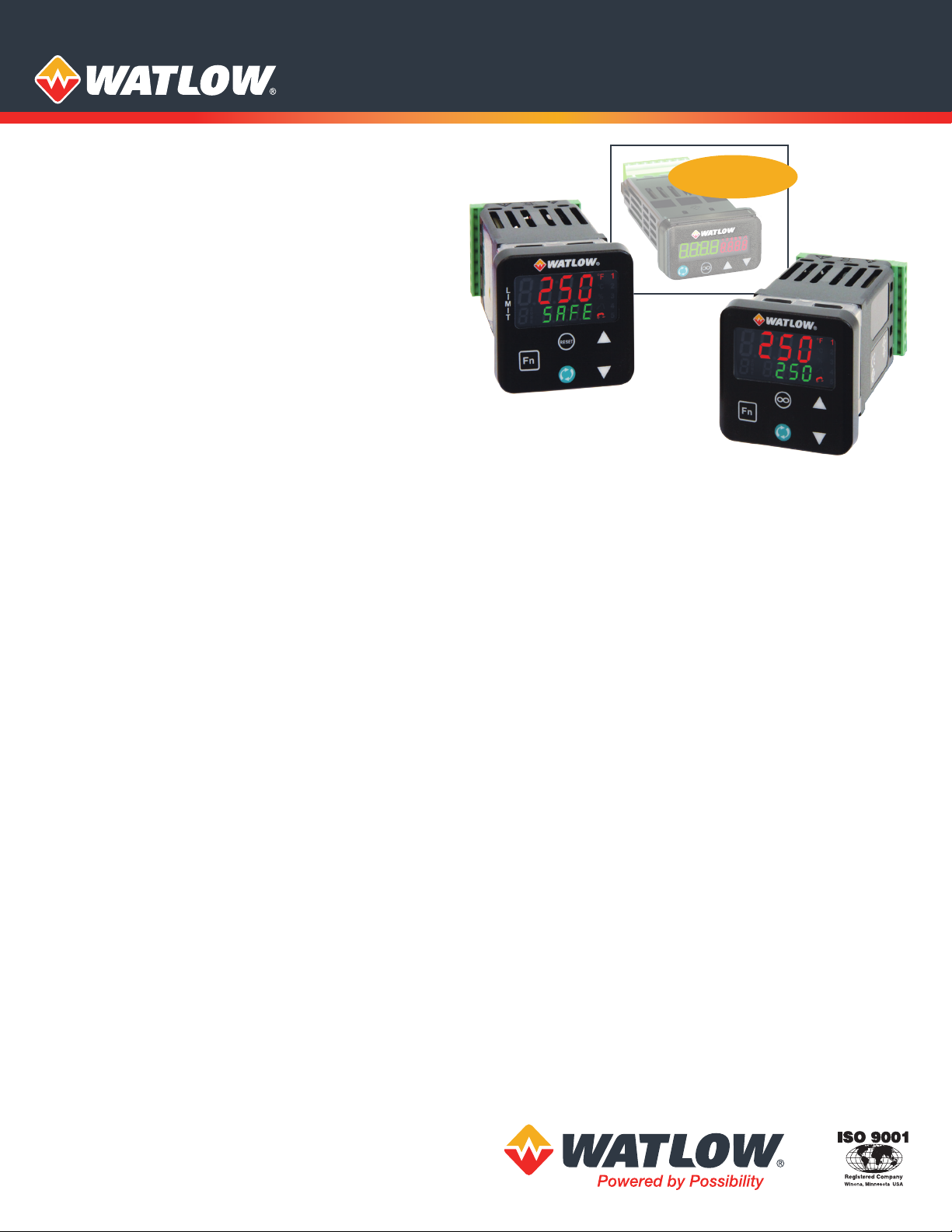
PM LEGACY™ Panel Mount Controller
1
/32 DIN
Available Soon
The Watlow® PM LEGACY™ series panel mount controller is
an industry leading PID controller that allows optimal
performance utilizing simple control and menu functionality
without complex features. It is ideally suited for basic
applications and usage levels.
The LEGACY includes one universal input and an option for
up to two outputs and is available in 1/32, and 1/16 DIN panel
mount packages. It can be ordered as a PID process controller
or as a dedicated over and under-temperature limit controller.
Features and Benefits
Simplified menu
• Fits basic applications with a user-friendly interface
supported by two menus and a streamlined list of
parameters
• Eliminates user complexity often experienced with more
advanced controllers and unnecessary features
• Reduces user training costs and user programming errors
PID auto-tune
• Provides auto-tune for fast, efficient start-up
Standard bus communications
• Allows easy product configuration via PC communications
protocol and free software
• Saves time, simplifies programming process and improves
reliability of controller setup
Factory Mutual (FM) approved over and under limit with
auxiliary outputs
• Increases user and equipment safety for over and
under-temperature conditions
Function key
• Enables simple, one-touch operation of user-defined,
repetitive activities
Touch-safe package
• Increases installer and operator safety
• Complies with IP2X requirements
Features and Benefits (con’t)
EZ-LINK™ mobile application for iPhone® and Android™
• Expedites controller setup with intuitive navigation
• Simplifies setting parameters with plain text names and
descriptions
• Connects quickly and easily via Bluetooth® wireless
communications
SMOOTH TOUCH™ keypad
• Eliminates contamination points on the front of the
controller
• Prevents premature failure of mechanical components
• Creates a better seal on front panel
• Ensures an easy to clean surface
Agency approvals: UL® listed, CSA, CE, RoHS, W.E.E.E., FM,
SEMI F47-0200, Class 1, Div. 2 rating on selected models
• Assures prompt product acceptance
• Reduces end product documentation costs
P3T armor sealing system
• Compiles to NEMA 4X, IP66 and IP67 specifications
• Allows controller to be cleaned and washed
• Certified UL® 50 independent to NEMA 4X specification
Consistent Termination Labeling (CTL) connection system
• Simplifies switching between products
• Speeds up user’s system documentation
Three-year warranty
• Demonstrates Watlow’s reliability and product support
High-amperage power control output (1/16 DIN only)
• Drives 15 ampere resistive loads direct
• Reduces component count
• Saves panel space and simplifies wiring
• Reduces cost of ownership
Page 2

Specifications
Line Voltage/Power
• 85 to 264VAC, 47 to 63Hz
• 20 to 28VAC, +10/-15%; 50/60Hz, ±5%
• 12 to 40VDC
• 10VA (1/32 and 1/16 DIN)
• Data retention upon power failure via non-volatile memory
• Compliant with SEMI F47-0200, Figure R1-1 voltage sag
requirements @ 24VAC or higher
Environment
• 0 to 149°F (-18 to 65°C) operating temperature
• -40 to 185°F (-40 to 85°C) storage temperature
• 0 to 90% RH, non-condensing
Accuracy
• Calibration accuracy and sensor conformity: ±0.1%
of span, ±1°C @ the calibrated ambient temperature and
rated
line voltage
• Type S: 0.2%
• Type T below -50°C: 0.2%
• Calibration ambient temperature @ 77°F ±5°F (25°C ±3°C)
• Accuracy span: 1000°F (540°C) min.
• Temperature stability: ±0.1°F/°F (±0.1°C/°C) rise in ambient
max.
Agency Approvals
• cULus® UL/EN/CSA C22.2 No 61010-1 Listed, File E185611
•
CSA C22.2 No. 24, File 158031
• UL® 50 4X indoor locations, NEMA 4X, IP66, IP67 front seal
• cULus® ANSI/ISA 12.12.01-2007, CSA-C22.2 No. 213-1987,
Class 1, Div. 2, Groups A, B, C and D, temperature code T4A,
File E184390 (optional)
• CE, RoHS by design, W.E.E.E.
• FM Class 3545 (limit controls)
Controller
• User selectable heat/cool, on-off, P, PI, PD, PID or alarm
action, not valid for limit controllers
• Auto-tune with control algorithm
• Control sampling rates: input = 10Hz, outputs = 10Hz
• Input and output capacity per controller type ordering
information
Serial Communications
• Isolated communications
• Standard bus configuration protocol
Wiring Termination—Touch-Safe Terminals
• Input, power and controller output terminals are touch safe
removable 12 to 22 AWG
Universal Input
• Thermocouple, grounded or ungrounded sensors, greater
than 20MΩ input impedance, 2kΩ source resistance max.
• Non-isolated to switched dc and process output
• RTD 2- or 3-wire, platinum, 100Ω @ 0°C calibration to DIN
curve (0.00385 Ω/Ω/°C)
• Process, 4-20mA @ 100Ω, or 0-10VDC @ 20kΩ input
impedance; scalable
Functional Operating Range
Type J: -346 to 2192°F (-210 to 1200°C)
Type K: -454 to 2500°F (-270 to 1371°C)
Type T: -454 to 750°F (-270 to 400°C)
Type E: -454 to 1832°F (-270 to 1000°C)
Type N: -454 to 2372°F (-270 to 1300°C)
Type C: 32 to 4200°F (0 to 2315°C)
Type D: 32 to 4200°F (0 to 2315°C)
Type F: 32 to 2449°F (0 to 1343°C)
Type R: -58 to 3214°F (-50 to 1767°C)
Type S: -58 to 3214°F (-50 to 1767°C)
Type B: 32 to 3300°F (0 to 1816°C)
RTD (DIN): -328 to 1472°F (-200 to 800°C)
Process: -1999 to 9999 units
Output Hardware
• Switched dc = 22 to 32VDC @ 30mA
• Open collector = 30VDC max. @ 100mA max. current sink
• Solid state relay (SSR), Form A, 0.5A @ 24VAC min., 264VAC
max., opto-isolated, without contact suppression
• Electromechanical relay, Form C, 24 to 240VAC or 30VDC
max., 5A resistive load, 100,000 cycles at rated load
• Electromechanical relay, Form A, 24 to 240VAC or 30VDC
max., 5A resistive load, 100,000 cycles at rated load
• Output 2 is limit for limit models
• NO-ARC relay, Form A, 24 to 240VAC, 15A @ 122°F (50°C),
resistive load, no VDC, 2 million cycles at rated load
• Universal process output: range selectable; 0 to 10VDC
±15mV into a min. 1,000Ω load with 2.5mV nominal
resolution; 4 to 20mA ±30µA into max. 800Ω load with 5µA
nominal resolution; temperature stability 100ppm/°C
Operator Interface
• Dual 4 digit, 7 segment LED displays
• Typical display update rate 1Hz
• Advance, infinity (RESET), up and down keys plus a
FUNCTION KEY (not available in 1/32 DIN)
• Infinity key is also labeled RESET on limit control models
• FUNCTION KEY on 1/16 DIN package automatically
programmed as an auto/manual transfer mode function
on PID models.
Page 3

Typical Block Diagram
2.10 in.
(107.18 mm)
EZ-LINK App
®
250°F
1 2 3
+
4 5 6
7 8 9
+
-
x
/
-
0
User Power
Supply
Fn
Dimensional Drawings
PM LEGACY 1/32 DIN
2.10 in.
(53.34 mm)
1.22 in.
(30.98 mm)
Process
Sensor
Switching
0.40 in.
(10.16 mm)
Power
Device
Heat
Source
LOAD
Limit
Sensor
Safety
Contactor
User Power
Supply
Mounting Panel
PM LEGACY 1/16 DIN
(53.34 mm)
2.10 in.
(53.34 mm)
Mounting Panel
1.38 in.
(35.05 mm)
0.40 in.
(10.16 mm)
1.38 in.
(35.05 mm)
4.22 in.
(107.18 mm)
4.22 in.
Page 4

Comparison of Available Features
1
⁄32 DIN
PID Loops 1 1
Profile Ramp/Soak 40 total steps None
Full Menu Yes None
Express Menu Yes Yes
Number of Digital Inputs/Outputs 0 to 2 0 to 2
Number of Outputs 1 to 4 1 to 6
Integrated Limits None None
Discrete Limit Yes Yes
Maximum Power Output 5A mechanical relay 15A NO-ARC
Current Measurement None None
Standard Bus Communications Yes Yes
Bluetooth® Technology Yes Yes
Field Bus Communications Modbus® RTU 485 Limit only
10-Point Calibration Offset Yes Yes
Countdown Timer Yes None
1
⁄16 DIN
Compatible Accessories
More information is available on these products at
www.watlow.com
Watlow’s new EZ-LINK™w app allows users
Connected Device
1 EZ-ZONE PM
All Parameters
Value
No
75°F
Active Set Point
0.0%
Heat Power
0.0%
Heat Power
70°F
Active Process
Auto
Control Mode
Control Mode
EZ-Link App at for Android™ or
for iPhone®.
to easily setup, monitor and adjust Watlow
PM PLUS controllers via Bluetooth®. The
app is available free-of-charge from the
app store for phones and tablets,
and provides access to the controller’s
parameters with fully spelled out names
in plain text with help topics that explain
each parameter and option. EZ-LINK
mobile application connects quickly
ContactDeviceAlertsDashboard
ContactDeviceAlertsDashboard
and easily via Bluetooth® wireless
communications. Download the
EZ-LINK
commissioning new controllers including managing the
inputs and outputs from pluggable flex modules, setting up
functions such as control loops and alarms and creating and
editing profiles. COMPOSER software is available for download
at www.watlow.com.
COMPOSER is Watlow’s
easy-to-use software for
configuring and customizing
controllers. Use it to optimize
Watlow’s F4T and PM PLUS
and RM controllers for specific
applications. Task-specific
views simplify all aspects of
SpecView is designed for
industrial users with features
such as data logging, trending
and support for bar code
readers and touch screens. Errors
are reduced, for any process, by
creating application-specific
screens. The software provides a
historical replay option, easy-to-use recipe features and remote
access options, including LAN, Internet and modem.
Silver Series EM touch
screen operator interface
terminals provide a
customizable user
interface, email event
notifications and log and
graph data for Watlow
controllers and other
devices. A Silver Series EM
operator interface terminal
paired with Watlow
controllers is the perfect solution for your industrial
process or machine control application.
Page 5

PM LEGACY™ Control Configuration Information
① ②
③
Package
Size
④
Primary
Functions
⑤
Power
Supply,
Digital I/O
⑥ ⑦
Output 1 and
2 Hardware
Options
⑧
Comm.
Options
PM
③
3 =1/32 DIN (coming soon)
6 =1/16 DIN
④
C =
PID controller with universal input
PID controller with universal input and profiling ramp/soak
R =
(Not available on 1/16 DIN or Express version)
PID controller with universal input and countdown timer
T =
(Not available on 1/16 DIN or Express version)
J =
PID controller with thermistor input (Not available on
1
/16 DIN or Express version)
PID controller with universal input and profiling ramp/soak
N =
(Not available on 1/16 DIN or Express version)
⑤
1 =
100 to 240VAC
2 =
100 to 240VAC plus 2 digital I/O points (Not available on 1/16
Power Supply, Digital Inputs/Outputs (I/O)
DIN or Express version)
3 =
20 to 28VAC or 12 to 40VDC
20 to 28VAC or 12 to 40VDC, plus 2 digital I/O points (Not
4 =
available on 1/16 DIN or Express version)
⑦
⑥
Output 1 and 2 Hardware Options
Output 1 Output 2
CA =
Switched dc/open collector None
CH* =
Switched dc/open collector NO-ARC 15A power control
CC =
Switched dc/open collector Switched dc
CJ =
Switched dc/open collector Mechanical relay 5A, Form A
CK =
Switched dc/open collector SSR Form A, 0.5A
EA =
Mechanical relay 5A, Form C None
EH* =
Mechanical relay 5A, Form C NO-ARC 15A power control
EC =
Mechanical relay 5A, Form C Switched dc
EJ =
Mechanical relay 5A, Form C Mechanical relay 5A, Form A
EK =
Mechanical relay 5A, Form C SSR Form A, 0.5A
FA =
Universal process None
FC =
Universal process Switched dc
FJ =
Universal process Mechanical relay 5A, Form A
FK =
Universal process SSR Form A, 0.5A
AK =
None SSR Form A, 0.5A
KH* =
SSR Form A, 0.5A NO-ARC 15A power control
KK =
SSR Form A, 0.5A SSR Form A, 0.5A
*CH, EH, KH - Not available with the 1/32 DIN (PM3) package size.
Package Size
Primary Functions
⑨ ⑩ ⑪
Future
Options
A A A
⑫
Model
Selection
⑧
⑬ ⑭
Custom
Options
Communication Options
Standard bus always included
A =
None
Bluetooth®
B =
E =
EIA-85 Modbus® RTU and Bluetooth® (Not available on
1
/16 DIN or Express version)
1 =
EIA-485 Modbus® RTU (Not available on 1/16 DIN or Express
version)
Note: Bluetooth® not available in all countries, contact factory.
⑫
Model Selection
N = PM LEGACY Version (Only available in PM3) (Input 1 always
isolated)
H = PM LEGACY EXPRESS Version (Available in PM3 or PM6)
(Input 1 always isolated)
⑭
⑬
WP =
Watlow logo face plate
No logo/no name face plate
WN
=
Conformal coating
AG =
12 =
Class 1, Div. 2 (not available with mechanical relay Output
Custom Options
Types E, H or J)
Page 6

PM LEGACY Limit Model Configuration Information
① ②
③
Package
Size
④
Primary
Functions
⑤
Power
Supply,
Digital I/O
⑥ ⑦
Output 1 and
2 Hardware
Options
PM
③
3 =1/32 DIN (coming soon)
6 =1/16 DIN
④
L =
Limit controller with universal input
Limit controller with thermistor input
M =
⑤
100 to 240VAC
1 =
2 =
100 to 240VAC plus 2 digital I/O points (Not available on
Power Supply, Digital Inputs/Outputs (I/O)
Express version)
3 =
20 to 28VAC or 12 to 40VDC
4 =
20 to 28VAC or 12 to 40VDC, plus 2 digital I/O points (Not
available on Express version)
⑦
⑥
Output 1 and 2 Hardware Options
Output 1 Output 2
AJ =
None
CJ =
Switched dc/open collector Mechanical relay 5A, Form A
EJ =
Mechanical relay 5A, Form C Mechanical relay 5A, Form A
⑧
Standard bus always included
A =
None
B =
Bluetooth®
E = EIA-485 Modbus® RTU and Bluetooth®
Express version)
F =
Modbus® RTU 232/485 and Bluetooth® (Not available on
PM3 or Express version)
G =
EtherNet/IP™/Modbus® TCP and Bluetooth® (Not available
on PM3 or Express version)
H =
DeviceNet™ and Bluetooth® (Not available on PM3 or
Express version)
J =
PROFIBUS DP and Bluetooth® (Not available on PM3 or
Express version)
1 =
EIA-485 Modbus® RTU (Not available on Express version)
2 =
EIA-232/485 Modbus® RTU (Not available on PM3 or Express
version)
3 =
EtherNet/IP™/Modbus® TCP (Not available on PM3 or
Express version)
5 =
DeviceNet™ (Not available on PM3 or Express version)
PROFIBUS DP
6 =
(Not available on PM3 or Express version)
Note: Bluetooth® not available in all countries, contact factory.
Package Size
Primary Functions
Mechanical relay 5A, Form A
Communication Options
(Not available on
⑧
Comm.
Options
⑨
Future
Option
A
Watlow® and EZ-ZONE® are registered trademarks of Watlow Electric Manufacturing
Company.
SMOOTH-TOUCH™, EZ-LINK™ and PM LEGACY™ are trademarks of Watlow Electric
Manufacturing Company.
UL® and cUL® are registered trademarks of Underwriter’s Laboratories, Inc.
i-Phone® is a registered trademark of Apple Corporation.
Android™ is a trademark of Google LLC.
⑩ ⑪
⑫
⑬ ⑭
Output 3 and
4 Hardware
Options
⑩
⑪
Model
Selection
Output 3 and 4 Hardware Options
Custom
Options
Output 3 Output 4
AA =
None None
AJ =
None Mechanical relay 5A, Form A
AK =
None SSR Form A, 0.5 A
CA =
Switched dc/open collector None
CC =
Switched dc/open collector Switched dc
CJ =
Switched dc/open collector Mechanical relay 5A, Form A
CK =
Switched dc/open collector SSR Form A, 0.5 A
EA =
Mechanical relay 5A, Form C None
EC =
Mechanical relay 5A, Form C Switched dc
EJ =
Mechanical relay 5A, Form C Mechanical relay 5A, Form A
EK =
Mechanical relay 5A, Form C SSR Form A, 0.5A
FA =
Universal process None
FC =
Universal process Switched dc
FJ =
Universal process Mechanical relay 5A, Form A
FK =
Universal process SSR Form A, 0.5A
KK =
SSR Form A, 0.5A SSR Form A, 0.5A
Note: Only available on 1/16 DIN models if communication Options F,
G, H, J or 2 thru 6 is ordered in previous digit, then Option AA must
be ordered here.
⑫
Model Selection
G = PM LEGACY Version (Input 1 always isolated)
H = PM LEGACY EXPRESS Version (Available in PM3 or PM6)
(Input 1 always isolated)
⑭
⑬
WP =
Watlow logo face plate
No logo/no name face plate
WN
=
Conformal coating
AG =
Custom Options
Powered by Possibility
To be automatically connected to the nearest
North American Technical Sales Oce:
1-800-WATLOW2 • www.watlow.com
©2020 Watlow Electric Manufacturing Company all rights reserved.
International Technical Sales Offices:
Austria +43 6244 20129 0
China +86 21 3532 8532
France +33 1 41 32 79 70
Germany +49 7253 9400 0
India +91 40 6661 2700
Italy +39 02 458 8841
Japan +81 3 3518 6630
Korea +82 2 2169 2600
Mexico +52 442 256 2200
Singapore +65 6773 9488
Spain +34 91 675 1292
Taiwan +886 7 288 5168
UK +44 115 964 0777
WIN-LEG-0820
 Loading...