

Page 1
User’s Manual
Series PD
Ethernet-Enabled
Temperature/Process Controller
1241 Bundy Boulevard., Winona, Minnesota USA 55987
Phone: +1 (507) 454-5300, Fax: +1 (507) 452-4507 http://www.watlow.com
Registered Company
Winona, Minnesota USA
0600-0043-0010 Rev. B Made in the U.S.A.
November 2006 $15.00
Page 2

Safety Information
We use note, caution and warning symbols throughout this book to draw your attention to
important operational and safety information.
A “NOTE” marks a short message to alert you to an important detail.
A “CAUTION” safety alert appears with information that is important for protecting your
equipment and performance. Be especially careful to read and follow all cautions that apply
to your application.
A “WARNING” safety alert appears with information that is important for protecting you,
others and equipment from damage. Pay very close attention to all warnings that apply to
your application.
The safety alert symbol, ç (an exclamation point in a triangle) precedes a general CAUTION
or WARNING statement.
The electrical hazard symbol, Ó (a lightning bolt in a triangle) precedes an electric shock
hazard CAUTION or WARNING safety statement.
Technical Assistance
If you encounter a problem with your Watlow controller, review your configuration information to verify that your selections are consistent with your application: inputs, outputs,
alarms, limits, etc. If the problem persists, you can get technical assistance from your local
Watlow representative (see back cover), by e-mailing your questions to wintechsupport@wat
low.com or by dialing +1 (507) 494-5656 between 7 a.m. and 5 p.m., Central Standard Time
(CST). Ask for for an Applications Engineer. Please have the following information available
when calling:
• Complete model number • All Series PD configuration information
• Quick Start Guide or User’s Manual • Computer Hardware / Software Configuration
Warranty
The Series PD is manufactured by ISO 9001-registered processes and is backed by a threeyear warranty.
Return Material Authorization (RMA)
1. Call Watlow Customer Service, (507) 454-5300, for a Return Material Authorization
(RMA) number before returning any item for repair. We need this information:
• Ship to address • Bill to address
• Contact name • Phone number
• Method of return shipment • Your P.O. number
• Detailed description of the problem • Any special instructions
• Name and phone number of person returning the product.
2. Prior approval and an RMA number, from the Customer Service Department, is needed
when returning any unused product for credit. Make sure the RMA number is on the outside
of the carton, and on all paperwork returned. Ship on a Freight Prepaid basis.
3. After we receive your return, we will examine the unit and try to verify the reason for
the return.
4. In cases of manufacturing defect, we will enter a repair order, replacement order or issue
credit for material returned.
5. To return products that are not defective, goods must be be in new condition, in the original boxes and they must be returned within 120 days of receipt. A 20 percent restocking
charge is applied for all returned stock controls and accessories.
6. If the unit is unrepairable, it will be returned to you with a letter of explanation.
7. Watlow reserves the right to charge for no trouble found (NTF) returns.
The Series PD User’s Manual is copyrighted by Watlow Winona, Inc., © November 2003 with all
rights reserved. (2413)
ç
CAUTION or
WARNING
Ó
Electrical
Shock Hazard
CAUTION or WARNING
Page 3

Watlow Series PD ■ 1 ■ Table of Contents
Chapter 1 - Overview . . . . . . . . . . . . . . . . . . . . . . . . . .2
Chapter 2 - Install and Wire . . . . . . . . . . . . . . . . . . . .3
Dimensions . . . . . . . . . . . . . . . . . . . . . . . . . . . . . . .3
Mounting/Removal . . . . . . . . . . . . . . . . . . . . . . . . . .4
Connectors . . . . . . . . . . . . . . . . . . . . . . . . . . . . . . .5
Wiring . . . . . . . . . . . . . . . . . . . . . . . . . . . . . . . . . . . .6
Chapter 3 - Indicator Lights . . . . . . . . . . . . . . . . . . .19
Chapter 4 - Ethernet Communications . . . . . . . . . .20
Chapter 5 - Monitor Device Page . . . . . . . . . . . . . . .22
Navigation Frame . . . . . . . . . . . . . . . . . . . . . . . . .23
Chapter 6 - Device Information Page . . . . . . . . . . . .25
Chapter 7 - Device Configuration Page . . . . . . . . . .28
Inputs . . . . . . . . . . . . . . . . . . . . . . . . . . . . . . . . . . .29
Control Loops . . . . . . . . . . . . . . . . . . . . . . . . . . . .35
Outputs . . . . . . . . . . . . . . . . . . . . . . . . . . . . . . . . .39
Alarms . . . . . . . . . . . . . . . . . . . . . . . . . . . . . . . . . .43
Network . . . . . . . . . . . . . . . . . . . . . . . . . . . . . . . . .45
Datalogging . . . . . . . . . . . . . . . . . . . . . . . . . . . . . .51
File System . . . . . . . . . . . . . . . . . . . . . . . . . . . . . .55
Chapter 8 - Calibration Page . . . . . . . . . . . . . . . . . . .59
Chapter 9 - Parameter Table . . . . . . . . . . . . . . . . . . .62
Inputs . . . . . . . . . . . . . . . . . . . . . . . . . . . . . . . . . . .63
Control Loops . . . . . . . . . . . . . . . . . . . . . . . . . . . .76
Outputs . . . . . . . . . . . . . . . . . . . . . . . . . . . . . . . . .90
Alarms . . . . . . . . . . . . . . . . . . . . . . . . . . . . . . . . .100
Network . . . . . . . . . . . . . . . . . . . . . . . . . . . . . . . .116
Datalogging . . . . . . . . . . . . . . . . . . . . . . . . . . . . .118
Hardware . . . . . . . . . . . . . . . . . . . . . . . . . . . . . . .122
Firmware . . . . . . . . . . . . . . . . . . . . . . . . . . . . . . .127
Chapter 10 - Features . . . . . . . . . . . . . . . . . . . . . . .129
Chapter 11 - Troubleshooting . . . . . . . . . . . . . . . . .144
Appendix . . . . . . . . . . . . . . . . . . . . . . . . . . . . . . . . . .146
Specifications . . . . . . . . . . . . . . . . . . . . . . . . . . . .146
Ordering Information . . . . . . . . . . . . . . . . . . . . . .148
Declaration of Conformity . . . . . . .inside back cover
TC
Table of Contents
Page 4
Watlow Series PD ■ 2 ■ Chapter 1 Overview
The Series PD controller is a DIN rail mounted, general purpose industrial PID temperature/
process controller. The Series PD is available in single and dual channel versions and features an
embedded web server to provide an easy to use interface for configuration and monitoring of
processes. The controller also features several popular communications protocols to facilitate easy
integration into most existing process management systems.
The Series PD accepts thermocouple, RTD and process signal control inputs and also features
auxiliary digital inputs or optional current transformer (CT) inputs. Up to four control or event
(alarm) outputs can be selected on either the single or dual channel versions.
Advanced features of the Series PD controllers include internal datalogging of key control parameters, INFOSENSE-P™ sensor technology, heater burn out detection and an enhanced control
algorithm.
The SERIES PD controller is backed by a three-year warranty from Watlow Winona and is
UL®508, C-UL®, CSA and CE approved.
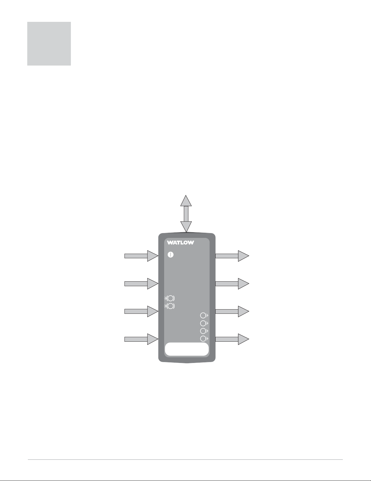
Figure 2 — Series PD inputs and outputs.
1
Overview
Ethernet Communications
1 or 2 Universal
Analog Inputs
(Single or dual channel)
1
2
Event or Current
Tr ansformer (CT) Inputs
Address
PID Controller
Power
Ethernet Link
Ethernet Activity
Input Error
Input Error
Output
Output
Output
Output
PD
4 outputs can be configured
as control or event (alarm)
outputs. Any output can be
assigned to either channel 1 or 2.
1
2
3
4
Page 5
Watlow Series PD ■ 3 ■ Chapter 2 Install and Wire
ç
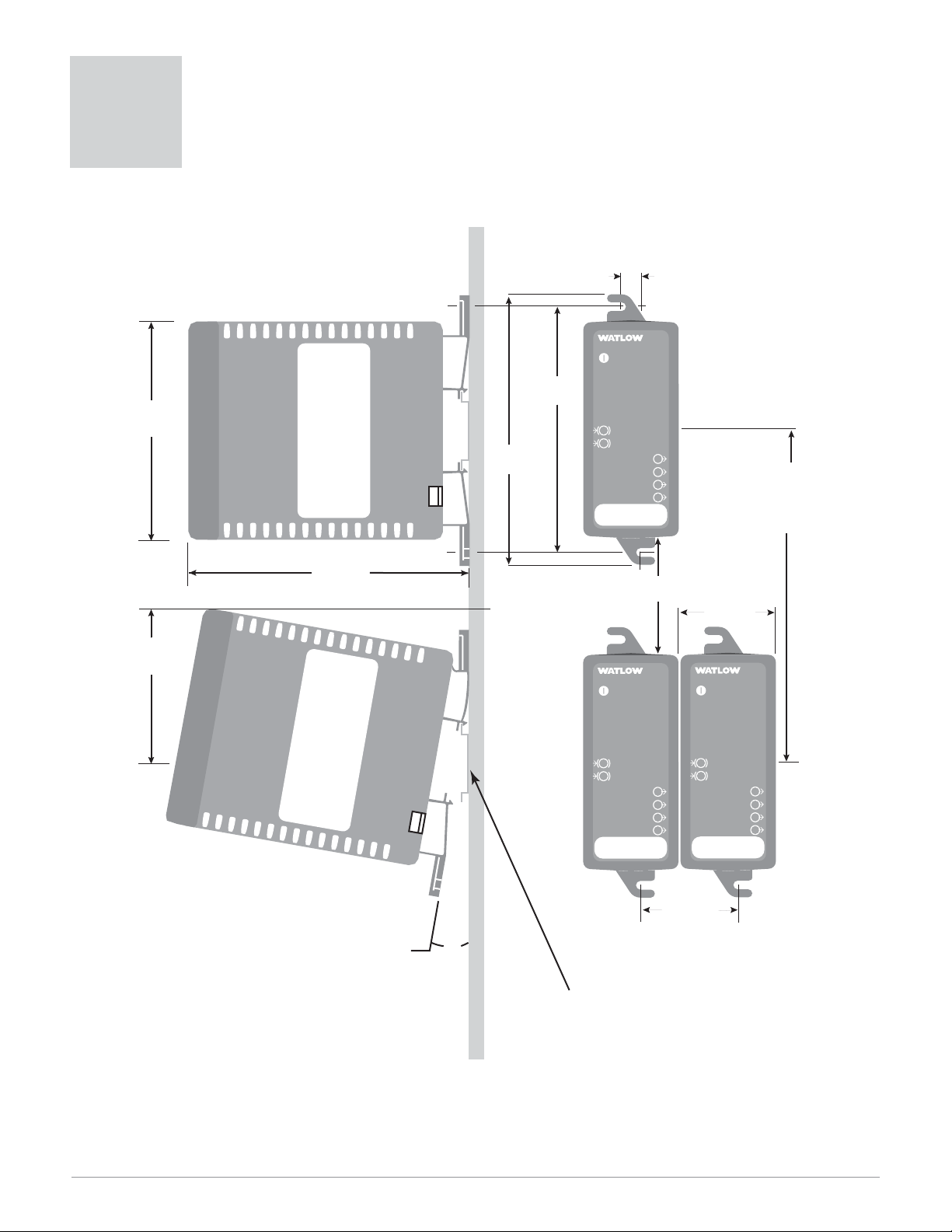
Caution: Maintain the correct spacing between rows of controllers to allow sufficient air circulation and installation clearance. Failure to do so could result in
damage to equipment.
Figure 3 — Series PD dimensions
2
Install and Wire
Series PD Dimensions
95.3 mm
(3.75 in)
72.9 mm
(2.87 in)
Side View
128.5 mm
(5.06 in)
DIN
rail
panel mounting
(M3.5 or #6
screw required)
118.4 mm
(4.66 in)
bracket for
107.7 mm
(4.24 in)
8.1 mm
(0.32 in)
PD
PID Controller
Power
Ethernet Link
Ethernet Activity
Input Error
1
2
Input Error
1
Output
2
Output
3
Address
Output
Output
4
Front View
Min. Clearance 51 mm
(2 in)
PD
PID Controller
Power
Ethernet Link
Ethernet Activity
Top/bottom
mount
hole offset
41.7 mm
(1.64 in)
PID Controller
Power
Ethernet Link
Ethernet Activity
Min. Clearance
between rail
centerlines
146.1 mm
(5.75 in)
PD
DIN
rail
1
2
Address
Input Error
Input Error
Output
Output
Output
Output
1
2
3
4
1
2
Address
Input Error
Input Error
Output
Output
Output
Output
1
2
3
4
41.9 mm
(1.65 in)
Attachment Angle
10˚
Use DIN EN 50022 35 X 7.5 mm rail
Page 6
Watlow Series PD ■ 4 ■ Chapter 2 Install and Wire
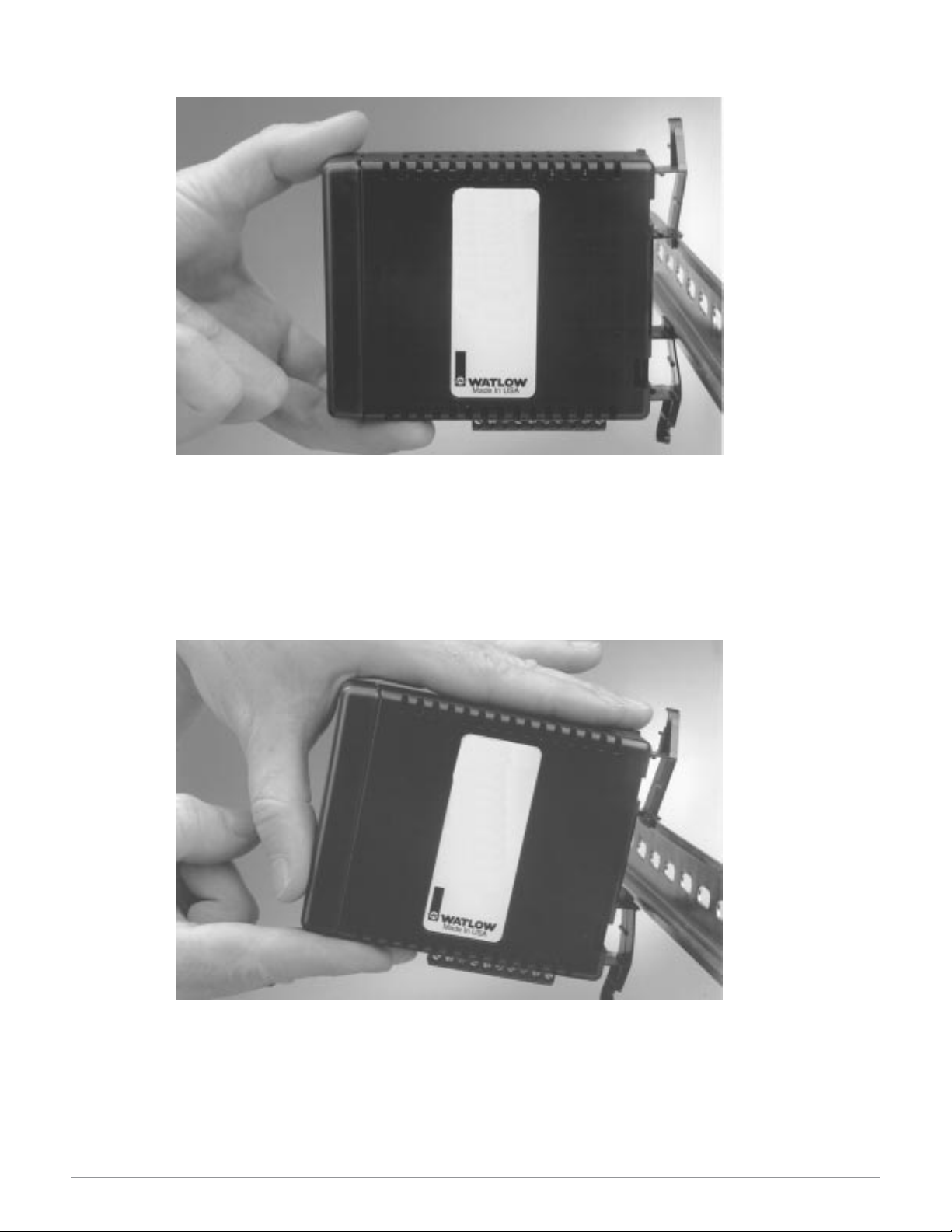
Mounting the Series PD
Figure 4a — Mounting
1. Push unit in and down to catch rail hook on top of rail.
2. Rotate bottom of unit toward rail.
3. Rail clasp will audibly “snap” into place. If the Series PD does not snap into place, check to
see if the rail is bent.
Removing the Series PD
Figure 4b — Removal
1. Press down on back of the Series PD until the bottom hook clears the rail.
2. Rotate bottom up and away from rail.
Page 7
Watlow Series PD ■ 5 ■ Chapter 2 Install and Wire
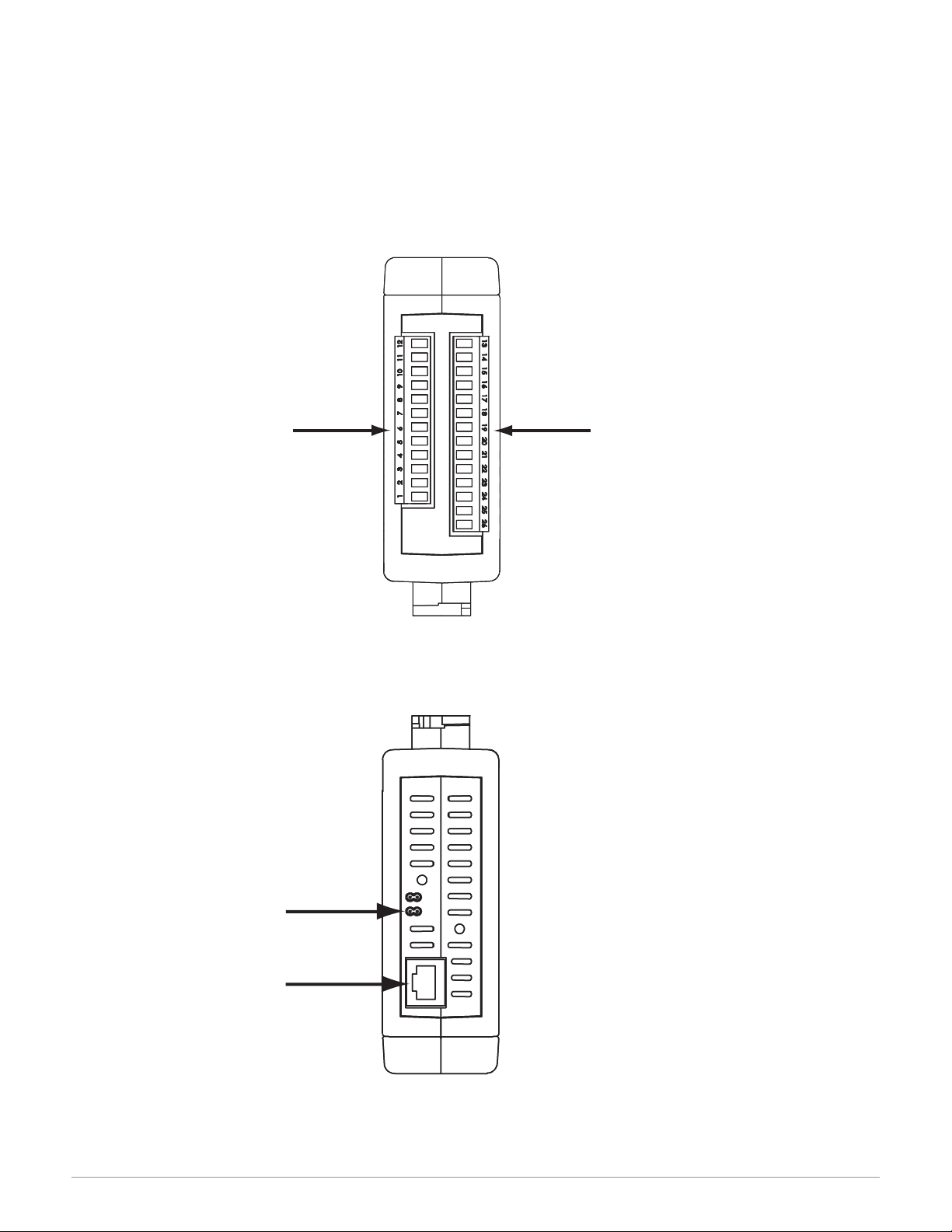
Series PD Connector Locations
Two connectors on the bottom of the unit provide connection points for the input power, inputs
and outputs. These connectors are removable and each terminal position is numbered.
The RJ-45 connector is located on the top of the Series PD to allow connection to an Ethernet
network.
Input and Output Connectors
Figure 5a — Input and Output Connectors
Ethernet RJ-45 Connector
Figure 5b — RJ-45 Connector
Bottom View
Input Connector
Controller Power and
Output Connector
Jumper to default
IP address on
power up
Ethernet RJ-45
Connector
Page 8
Watlow Series PD ■ 6 ■ Chapter 2 Install and Wire
Ó
Warning:
Use National Electric (NEC) or
other country-specific standard
wiring and safety practices when
wiring and connecting this controller to a power source and to
electrical sensors or peripheral
devices. Failure to do so may result in damage to equipment and
property, and/or injury or loss of
life.
Ó
WARNING: If high voltage is applied to the controller, irreversible damage will occur.
Note: 24 VÅÅinput power required to use single cycle,variable time base output function.
Wiring the Series PD
The model number for each output option appears with its wiring diagram.
Check the label on the controller and compare your model number to those
shown here and to the model number breakdown in the Appendix of this
manual.
All outputs are referenced to a de-energized state.
All wiring and fusing must conform to the National Electric Code and to
any locally applicable codes as well.
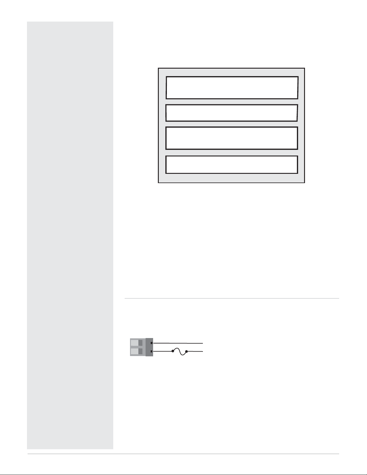
Figure 6a — Power Wiring
(all model numbers)
• Nominal voltage: 24V‡ (ac/dc)
Isolation Blocks
There are no electrical connections between these blocks
Relay outputs (mechanical and solid-state) provide isolation through their
relay contacts. Each relay output is isolated from the blocks above and is
isolated from other relay outputs.
Analog Input 1
Digital Inputs
Current Transformer Inputs
Analog Input 2
Control Outputs
Alarm Outputs
Retransmit Outputs
Communications
25 26
25
26
L2
L1
-
+
24V‡ (ac/dc)
Page 9
Watlow Series PD ■ 7 ■ Chapter 2 Install and Wire
Ó
Warning:
Use National Electric (NEC) or
other country-specific standard
wiring and safety practices when
wiring and connecting this controller to a power source and to
electrical sensors or peripheral
devices. Failure to do so may result in damage to equipment and
property, and/or injury or loss of
life.
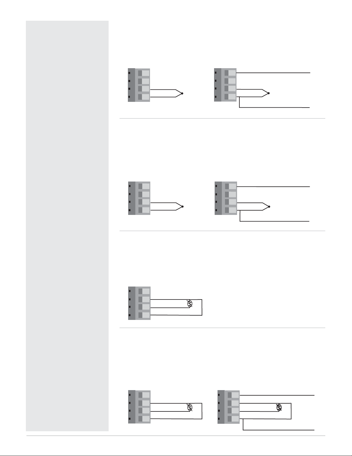
Figure 7a — Thermocouple Input 1
(all model numbers)
Thermocouples are polarity sensitive. The negative lead (usually red) must be
connected to terminal 9.
• Input impedance: >20 MΩ
Figure 7b — Thermocouple Input 2
PDD _-_ _ _ _-_ _ _ _
Thermocouples are polarity sensitive. The negative lead (usually red) must be
connected to terminal 5.
• Input impedance: >20 MΩ
• Input 2 isolated from Input 1
Figure 7c — 2-Wire RTD Input 1 (100 Ω DIN curve 0.00385
Ω/Ω/°C)
(all model numbers)
Terminals 9 and 11 must be shorted for a two-wire RTD.
• Nominal excitation current: 250 µA
Figure 7d — 3-Wire RTD Input 1 (100 Ω DIN curve 0.00385
Ω/Ω/°C)
(all model numbers)
The S1 lead (usually white) must be connected to terminal 10.
• Nominal excitation current: 250 µA
12 INFOSENSE-P™ DATA
10 +
9 -
INFOSENSE-P™ GND
9 10 11 12
10 +
9 -
9 10 11 12
8 INFOSENSE-P™ DATA
5 6 7 8
6 +
5 -
5 6 7 8
6 +
5 -
INFOSENSE-P™ GND
11 S2
10 S1
9 10 11 12
9
12 INFOSENSE-P™ DATA
11 S2
10 S1
9 10 11 12
9 S3
9 10 11 12
11 S2
10 S1
9 S3
INFOSENSE-P™ GND
Page 10
Watlow Series PD ■ 8 ■ Chapter 2 Install and Wire
ç
Warning:
Use National Electric (NEC) or
other country-specific standard
wiring and safety practices when
wiring and connecting this controller to a power source and to
electrical sensors or peripheral
devices. Failure to do so may result in damage to equipment and
property, and/or injury or loss of
life.
ç
WARNING: Process input may
not have sensor break protection. Outputs can remain full on.
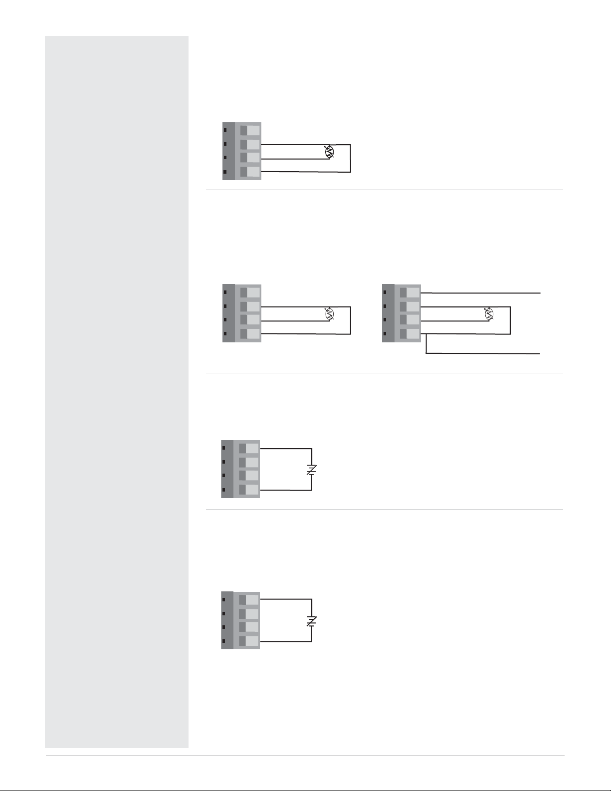
Figure 8a — 2-Wire RTD Input 2 (100 Ω DIN curve 0.00385
Ω/Ω/°C)
PDD _-_ _ _ _-_ _ _ _
Terminals 5 and 7 must be shorted for a two-wire RTD.
• Nominal excitation current: 250 µA
Figure 8b — 3-Wire RTD Input 2 (100 Ω DIN curve 0.00385
Ω/Ω/°C)
PDD _-_ _ _ _-_ _ _ _
The S1 lead (usually white) must be connected to terminal 6.
• Nominal excitation current: 250 µA
Figure 8c — Input 1, 0 to 10V
ÎÎ
(dc) Process Input
(all model numbers)
• Input impedance 20 kΩ, dc only
Figure 8d — Input 2, 0 to 10V
ÎÎ
(dc) Process Input
PDD _-_ _ _ _-_ _ _
• Input impedance 20 kΩ, dc only
• Input 2 isolated from Input 1
7 S2
6 S1
5 6 7 8
5
8 INFOSENSE™ DATA
5 6 7 8
7 S2
6 S1
5 S3
5 6 7 8
7 S2
6 S1
5 S3
INFOSENSE™ GND
12
9 10 11 12
+
-
9
+
8
-
5 6 7 8
5
Page 11
Watlow Series PD ■ 9 ■ Chapter 2 Install and Wire
Ó
Warning:
Use National Electric (NEC) or
other country-specific standard
wiring and safety practices when
wiring and connecting this controller to a power source and to
electrical sensors or peripheral
devices. Failure to do so may result in damage to equipment and
property, and/or injury or loss of
life.
ç
WARNING: Process input may
not have sensor break protection. Outputs can remain full on.
Note: Install a 1kΩ pull-down
resistor for each digital input using voltage inputs.
Note: Install a 10kΩ pull-up re-
sistor for each digital input
using contact closure inputs.
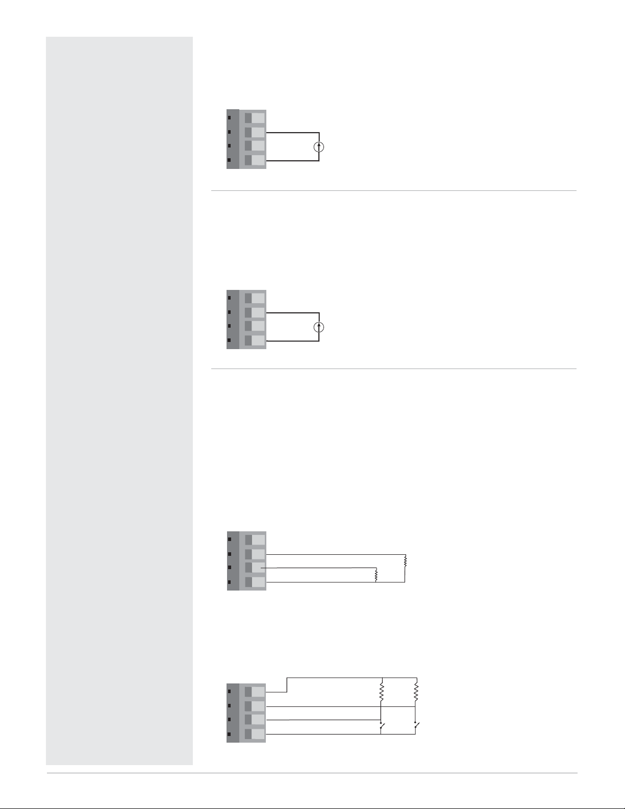
Figure 9a — Input 1, 0 to 20 mA Process Input
(all model numbers)
• Input impedance 100 Ω, dc only
• Controller does not supply power for the current loop
Figure 9b — Input 2, 0 to 20 mA Process Input
PDD _-_ _ _ _-_ _ _
• Input impedance 100 Ω, dc only
• Controller does not supply power for the current loop
• Input 2 isolated from Input 1
Dual Digital Inputs
PD_ 1-_ _ _ _-_ _ _
• Input impedance 10kΩ, dc only
• Input 2 isolated from Input 1
Figure 9c — Voltage input
0-1VÎ (dc) Event Input Low State
2-36VÎ (dc) Event Input High State
Figure 9d — Contact closure
0-2kΩ Event Input Low State
> 7kΩ Event Input High State
11
9 10 11 12
+
-
9
+
7
-
5 6 7 8
5
3
Digital Input 2 +
Digital Input 1 +
2
Digital Common
1 2 3 4
1 2 3 4
1
+5V‡ (dc)
4
3
Digital Input 2
Digital Input 1
2
1
Digital Common
1kΩ
-
10kΩ 10kΩ
1kΩ
Add a 1kΩ pull
down resistor for
each active input
Add a 10kΩ pull
up resistor for each
active input
Page 12
Watlow Series PD ■ 10 ■ Chapter 2 Install and Wire
ç
Warning:
Use National Electric (NEC) or
other country-specific standard
wiring and safety practices when
wiring and connecting this controller to a power source and to
electrical sensors or peripheral
devices. Failure to do so may result in damage to equipment and
property, and/or injury or loss of
life.
Note: Current transformer (CT)
must be purchased separately.
Note: A current transformer input
cannot be associated with a
process output on Output 1 or 3.
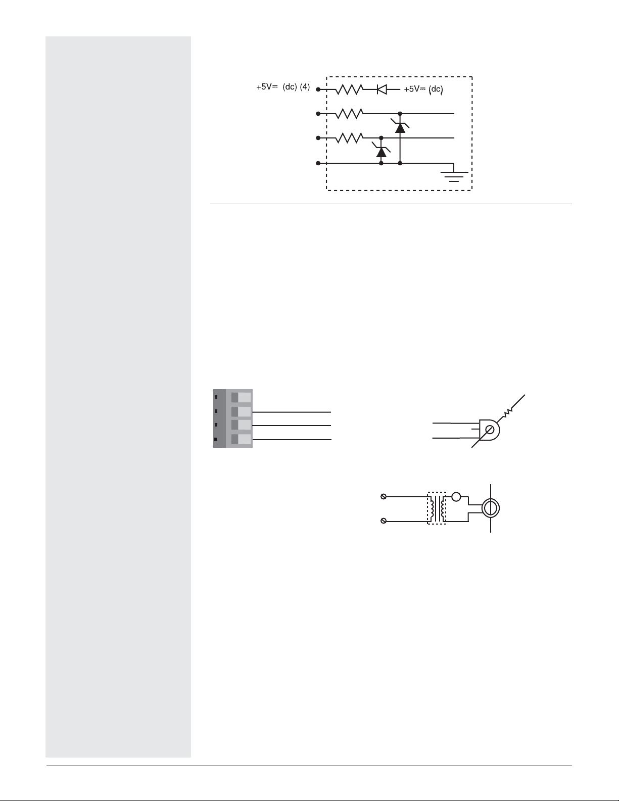
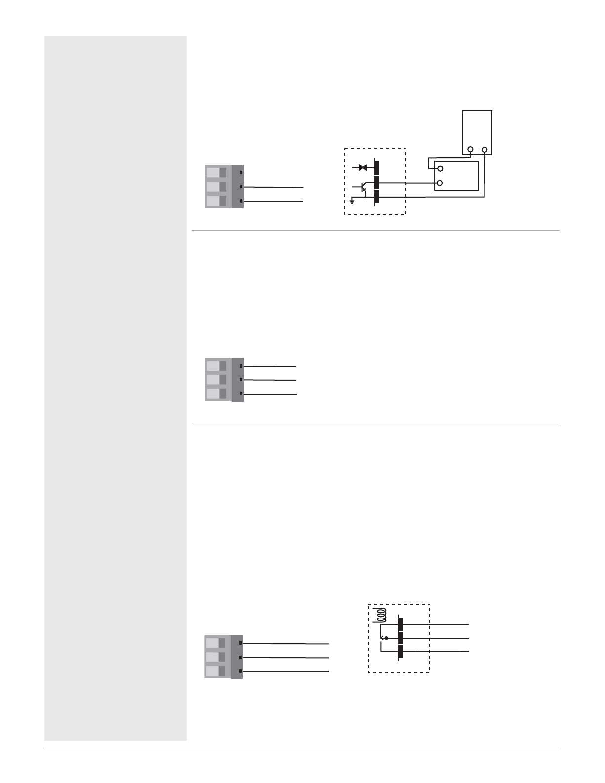
Figure 10a — Digital input internal circuit
Dual Current Transformer (CT) Inputs
PD_ 3-_ _ _ _-_ _ _
• Input impedance 100Ω, Vac only.
The current transformer (CT) must be purchased separately. Watlow CT
part number is 16-0246 (up to 50 amps).
Systems that are more than 50 amps need an interstage transformer. For
example, if you use a 300 amp CT, part number 16-0073, and an interstage
transformer, part number 16-0176, the 300 amp CT provides a 5 amp signal
to the interstage transformer. In turn, the interstage transformer provides a
20 mA maximum signal to the controller.
Figure 10b — Single Phase
Digital Input 2 (3)
Digital Input 1 (2)
Digital Input Common (1)
Internal Circuitry
3
CT Input 2
CT Input 1
1 2 3 4
2
1
CT Common
To CT Input 1 or 2
CT Input 1 or 2
CT Common
Single phase current sensing up to 300 amp
To CT Common
0 to
20mA
Transformer
16-0176
Load wire
CT
Center leg not used
L1
AC Load
A
0 to 5A
AC
L2
Page 13
Watlow Series PD ■ 11 ■ Chapter 2 Install and Wire
ç
Warning:
Use National Electric (NEC) or
other country-specific standard
wiring and safety practices when
wiring and connecting this controller to a power source and to
electrical sensors or peripheral
devices. Failure to do so may result in damage to equipment and
property, and/or injury or loss of
life.
Note: Current transformer (CT)
must be purchased separately.
Note: A current transformer input
cannot be associated with a
process output on Output 1 or 3.
Note: Install a 1kΩ pull-down
resistor for each digital input using voltage inputs.
Note: Install a 10kΩ pull-up re-
sistor for each digital input
using contact closure inputs.
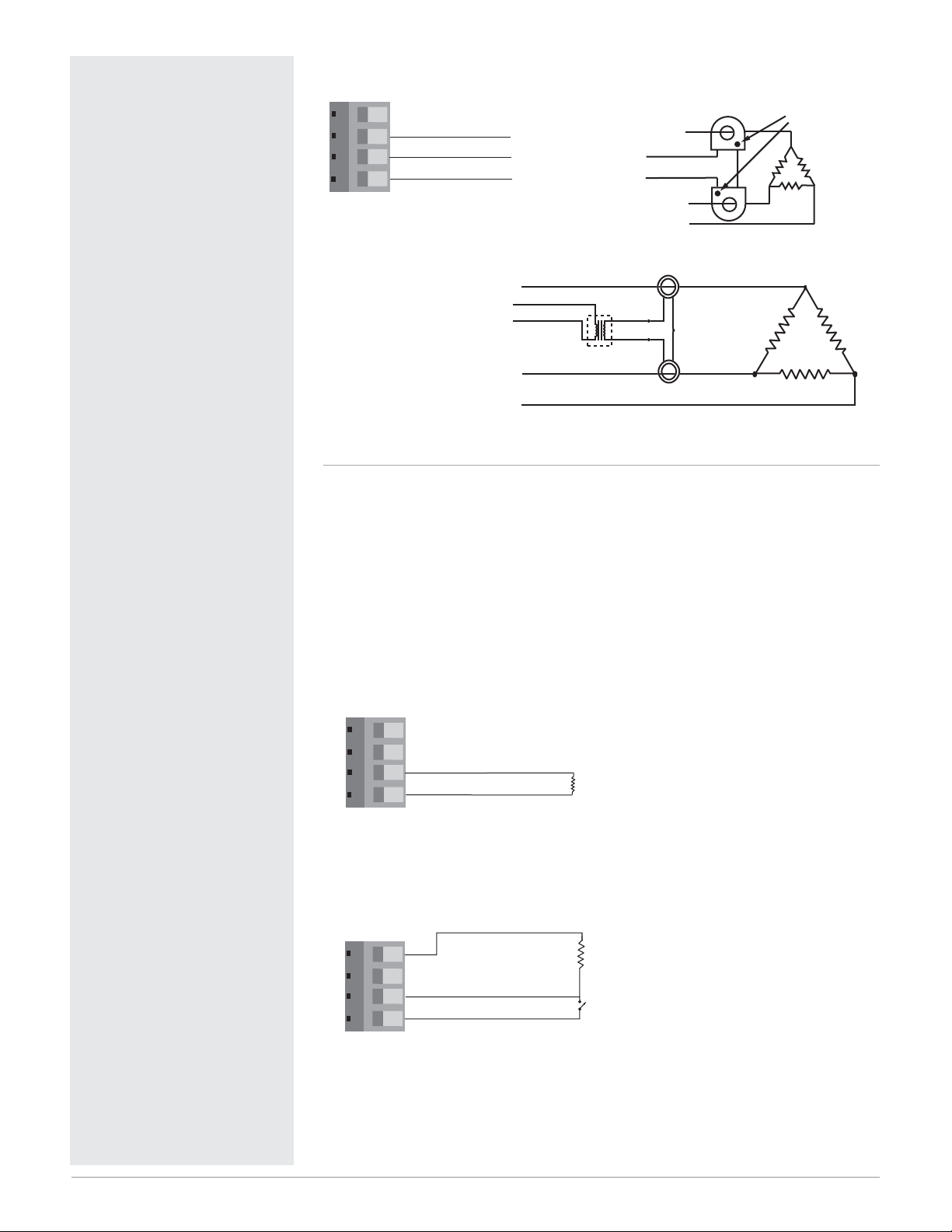
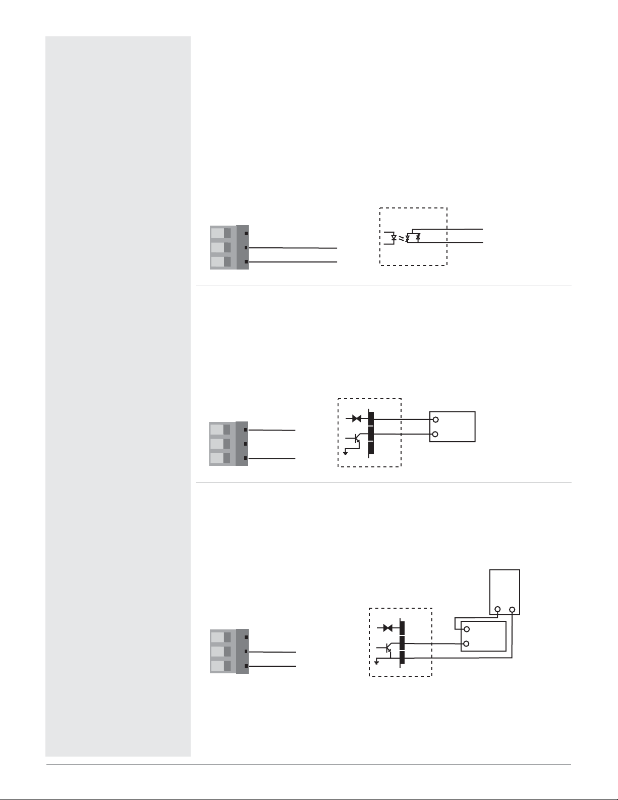
Figure 11a — Three Phase using Two Current Transformers
One Digital Input and One Current Transformer Input
PD_ 2-_ _ _ _-_ _ _
Digital Input 1
• Input impedance 10kΩ, dc only
Figure 11b — Voltage input
0-1VÎ (dc) Event Input Low State
2-36VÎ (dc) Event Input High State
Figure 11c — Contact closure
0-2kΩ Event Input Low State
> 7kΩ Event Input High State
Phase
dot
1 2 3 4
3
CT Input 2
CT Input 1
2
1
CT Common
L1
To CT Input 1 or 2
To CT Common
L3
L2
CT
L1
To CT Input 1 or 2
To CT Common
L3
L2
Red
Red
20mA
16-0176
Transformer
Bk
Bk
WhBk
5A
BkWh
CT
3-phase current sensing up to 300 amp
Digital Input 1 +
2
Digital Common
1 2 3 4
1 2 3 4
1
+5V‡ (dc)
4
3
Digital Input 1
2
1
Digital Common
Add a 1kΩ pull
down resistor for
1kΩ
-
10kΩ
each active input
Contact Closure
(add a 10kΩ pull
up resistor for each
active input)
Page 14
Watlow Series PD ■ 12 ■ Chapter 2 Install and Wire
ç
Warning:
Use National Electric (NEC) or
other country-specific standard
wiring and safety practices when
wiring and connecting this controller to a power source and to
electrical sensors or peripheral
devices. Failure to do so may result in damage to equipment and
property, and/or injury or loss of
life.
Note: Current transformer (CT)
must be purchased separately.
Note: A process output cannot be
installed on Output 1 or 3 when
using current transformer input.
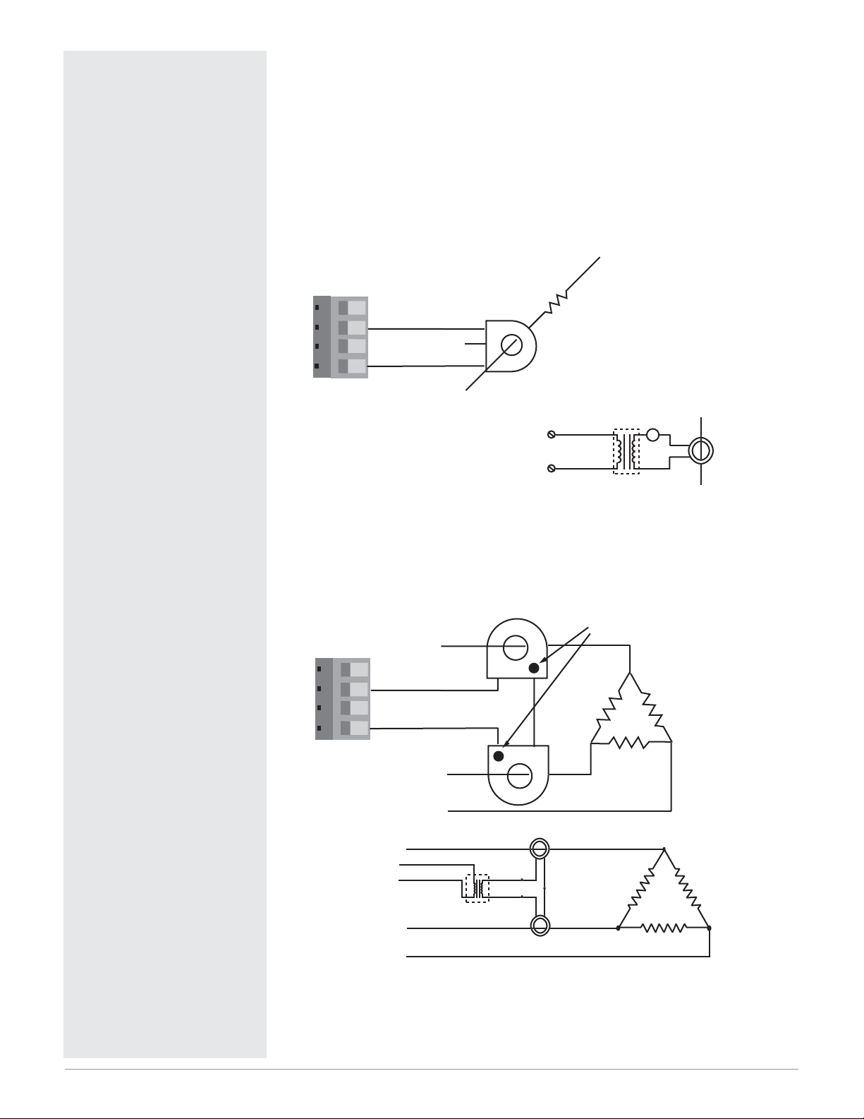
Figure 12a — Current Transformer Input 2, Single Phase
• Input impedance 100Ω, Vac only
The current transformer must be purchased separately. Watlow current
transformer part number is 16-0246 (up to 50 amps).
Systems that are more than 50 amps need an interstage transformer. For
example, if you use a 300 amp current transformer, part number 16-0073,
and an interstage transformer, part number 16-0176, the 300 amp current
transformer provides a 5 amp signal to the interstage transformer. In turn,
the interstage transformer provides a 20 mA maximum signal to the controller.
Figure 12b — Current Transformer Input 2, Three Phase
L2
Load wire
CT Input 2
CT
1 2 3 4
13CT Common
Center leg not used
L1
CT Input 2
CT Common
Single phase current sensing up to 300 amp
0 to
20mA
16-0176
Transformer
0 to 5A
AC Load
A
AC
Phase
dot
L1
CT Input 2
1 2 3 4
13CT Common
L3
L2
CT
L1
To CT Input 2
To CT Common
L3
L2
Red
Red
20mA
16-0176
Transformer
Bk
Bk
WhBk
5A
BkWh
CT
3-phase current sensing up to 300 amp
Page 15
Watlow Series PD ■ 13 ■ Chapter 2 Install and Wire
ç
Warning:
Use National Electric (NEC) or
other country-specific standard
wiring and safety practices when
wiring and connecting this controller to a power source and to
electrical sensors or peripheral
devices. Failure to do so may result in damage to equipment and
property, and/or injury or loss of
life.
Quencharc Note:
Switching pilot duty loads (relay
coils, solenoids, etc.) with the
mechanical relay or solid-state
relay output options requires use
of an R.C. suppressor.
Watlow carries the R.C. suppressor Quencharc brand name,
which is a trademark of ITW
Paktron. Watlow Part No. 08040147-0000.
Note: 24 VÅÅinput power required to use single cycle,variable time base output function.
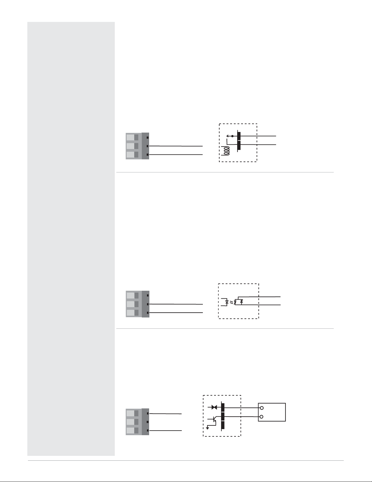
Figure 13a — Output 1 Mechanical Relay
PD_ _ - J _ _ _ - _ _ _ _
• Form A contact
• 2 A, resistive
• 125 VA pilot duty, 120/240VÅ (ac), inductive
• 240VÅ (ac) maximum
• 30VÎ (dc) maximum
• See Quencharc note
• For use with ac or dc
• Minimum load current 10 mA
• Output does not supply power
Figure 13b — Output 1 Solid-state Relay
PD_ _ - K _ _ _ - _ _ _ _
• Form A contact
• 0.5 A, resistive
• 20 VA pilot duty, 120/240VÅ (ac), inductive
• 24 to 240VÅ (ac)
• See Quencharc note
• Minimum load current 10 mA
• Maximum leakage current 100 µA
• Not for use with direct current (dc)
• Output does not supply power
Figure 13c — Output 1 Switched DC
PD_ _ - C_ _ _ - _ _ _ _
• Supply current 30 mAÎ (dc) maximum
• Supply voltage 24VÎ (dc)
• Not recommended for switching mechanical relays
• Output supplies power
Mechanical Relay
13 14 15
14 com
15 normally open
Internal Circuitry
13 14 15
14 com
15 normally open
Solid-state Relay
Solid-state Switch
Internal Circuitry
14
15
14
15
COM.
N.O.
COM.
N.O.
Switched DC
24VÎ (dc)
dc+
13 14 15
13 dc +
dc-
13
15
14 com
15 dc -
Internal Circuitry
+
Load
-
Page 16
Watlow Series PD ■ 14 ■ Chapter 2 Install and Wire
ç
Warning:
Use National Electric (NEC) or
other country-specific standard
wiring and safety practices when
wiring and connecting this controller to a power source and to
electrical sensors or peripheral
devices. Failure to do so may result in damage to equipment and
property, and/or injury or loss of
life.
Quencharc Note:
Switching pilot duty loads (relay
coils, solenoids, etc.) with the
mechanical relay or solid-state
relay output options requires use
of an R.C. suppressor.
Watlow carries the R.C. suppressor Quencharc brand name,
which is a trademark of ITW
Paktron. Watlow Part No. 08040147-0000.
Note: A current transformer input
is not available for Output 1 or 3
if a process output.
Note: 24 VÅÅinput power required to use single cycle,variable time base output function.
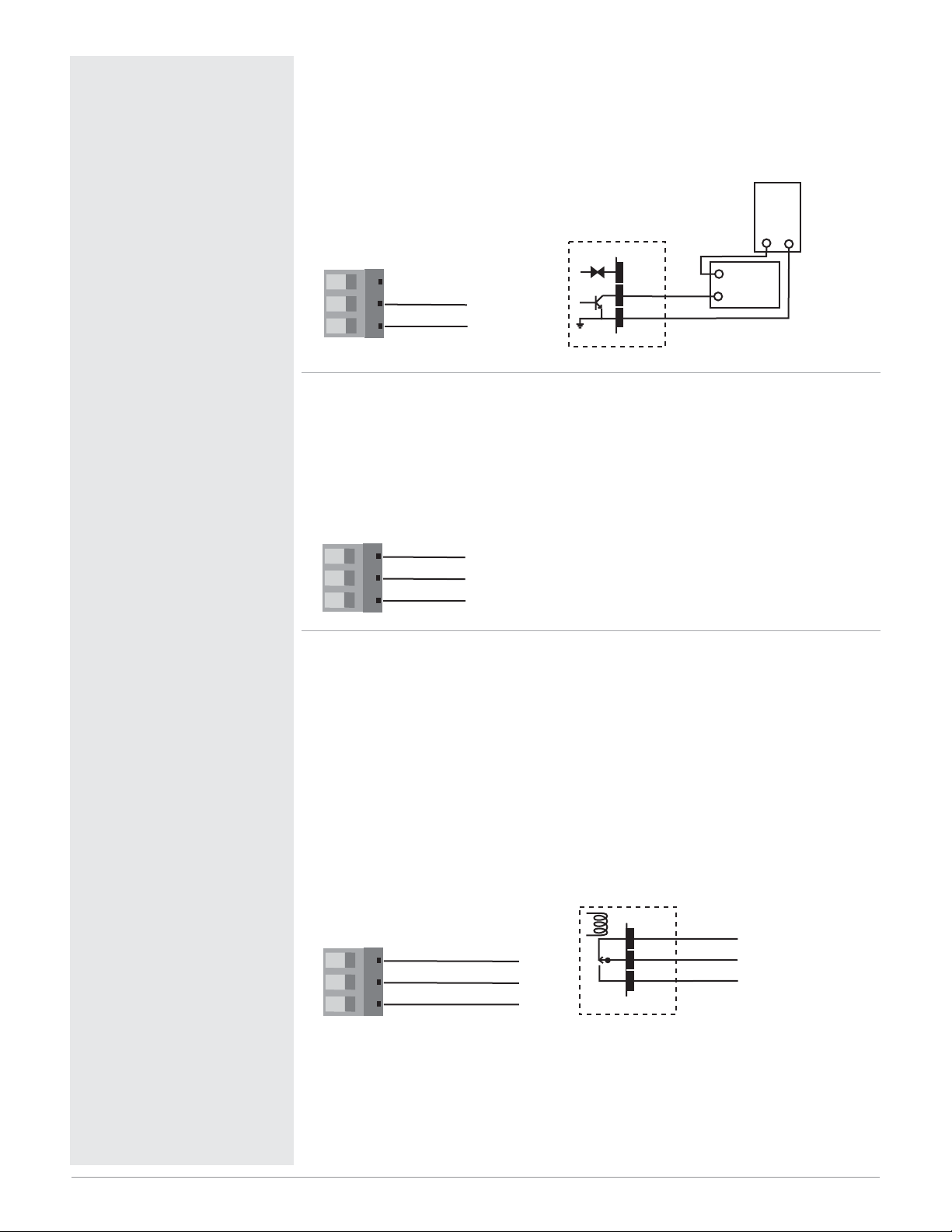
Figure 14a — Output 1 Open Collector
PD_ _ - C_ _ _ - _ _ _ _
• Maximum current sink 200 mAÎ (dc)
• Maximum supply voltage 42VÎ (dc)
• Output does not supply power
Figure 14b — Output 1 Process
PD_ _ - F_ _ _ - _ _ _ _
• Analog output is scalable between 0 to 10VÎ (dc) or 0 to 20 mAÎ (dc)
• Load capability: voltage 1 kΩ minimum; current 800 Ω maximum
• Output supplies power
• Cannot use voltage and current output at the same time
Figure 14c — Output 2 Mechanical Relay
PD_ _ - _ E _ _ - _ _ _ _
• Form C contacts
• 2 A, resistive
• 125 VA pilot duty, 120/240VÅ (ac), inductive
• 240VÅ (ac) maximum
• 30VÎ (dc) maximum
• See Quencharc note
• For use with ac or dc
• Minimum load current: 10 mA
• Output does not supply power
Class 2 power source
13 14 15
13 dc +
14 com
15 dc -
Open Collector
42VÎ (dc) maximum
dc+
dc-
COM.
Internal Circuitry
required for agency
compliance.
13
15
14
-
+
Load
Power
Supply
+
-
13 14 15
13 volts +
14 com 15 amps +
Mechanical Relay
16
16 17 18
16 normally closed
17 com
18 normally open
Internal Circuitry
N.C.
COM.
N.O.
17
18
Page 17
Watlow Series PD ■ 15 ■ Chapter 2 Install and Wire
ç
Warning:
Use National Electric (NEC) or
other country-specific standard
wiring and safety practices when
wiring and connecting this controller to a power source and to
electrical sensors or peripheral
devices. Failure to do so may result in damage to equipment and
property, and/or injury or loss of
life.
Quencharc Note:
Switching pilot duty loads (relay
coils, solenoids, etc.) with the
mechanical relay or solid-state
relay output options requires use
of an R.C. suppressor.
Watlow carries the R.C. suppressor Quencharc brand name,
which is a trademark of ITW
Paktron. Watlow Part No. 08040147-0000.
Note: 24 VÅÅinput power required to use single cycle,variable time base output function.
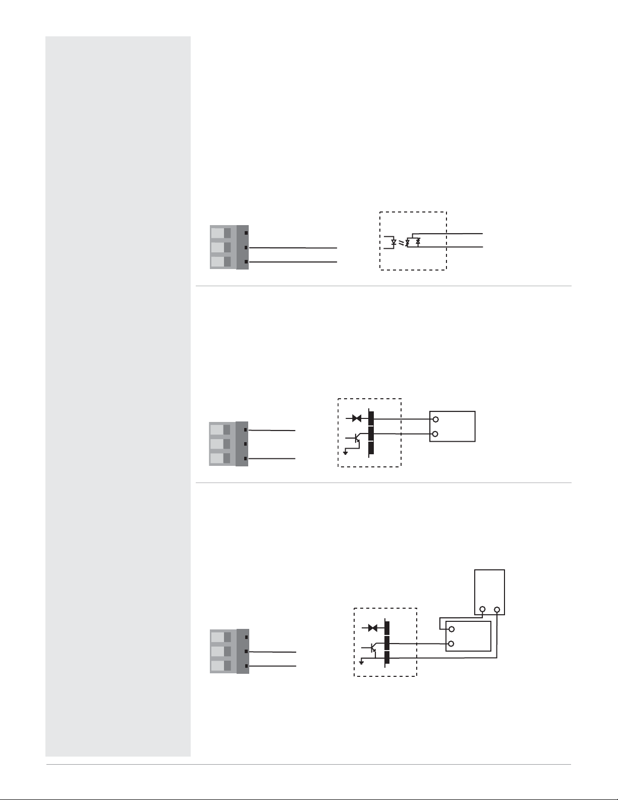
Figure 15a — Output 2 Solid-state Relay
PD_ _ - _ K _ _ - _ _ _ _
• Form A contact
• 0.5 A, resistive
• 20 VA pilot duty, 120/240VÅ (ac), inductive
• 24 to 240VÅ (ac)
• See Quencharc note
• Minimum load current 10mA
• Maximum leakage current 100µA
• Not for use with direct current (dc)
• Output does not supply power
Figure 15b — Output 2 Switched DC
PD_ _ - _ C _ _ - _ _ _ _
• Maximum supply current 30 mAÎ (dc)
• Supply voltage 24VÎ (dc)
• Not recommended for switching mechanical relays
• Output supplies power
Figure 15c — Output 2 Open Collector
PD_ _ - _ C _ _ - _ _ _ _
• Maximum current sink 200 mAÎ (dc)
• Maximum supply voltage 42VÎ (dc)
• Output does not supply power
16 17 18
Solid-state Relay
Solid-state Switch
17 com
18 normally open
Internal Circuitry
Switched DC
24VÎ (dc)
dc+
16 17 18
16 dc +
17 com
18 dc -
Internal Circuitry
dc-
16
18
+
-
17
18
Load
COM.
N.O.
Open Collector
42VÎ (dc) maximum
16 17 18
16 dc +
17 com
18 dc -
Internal Circuitry
Class 2 power source
required for agency
compliance.
dc+
16
dc-
18
COM.
17
+
-
Load
Power
Supply
+
-
Page 18
Watlow Series PD ■ 16 ■ Chapter 2 Install and Wire
ç
Warning:
Use National Electric (NEC) or
other country-specific standard
wiring and safety practices when
wiring and connecting this controller to a power source and to
electrical sensors or peripheral
devices. Failure to do so may result in damage to equipment and
property, and/or injury or loss of
life.
Quencharc Note:
Switching pilot duty loads (relay
coils, solenoids, etc.) with the
mechanical relay or solid-state
relay output options requires use
of an R.C. suppressor.
Watlow carries the R.C. suppressor Quencharc brand name,
which is a trademark of ITW
Paktron. Watlow Part No. 08040147-0000.
Note: 24 VÅÅinput power required to use single cycle,variable time base output function.
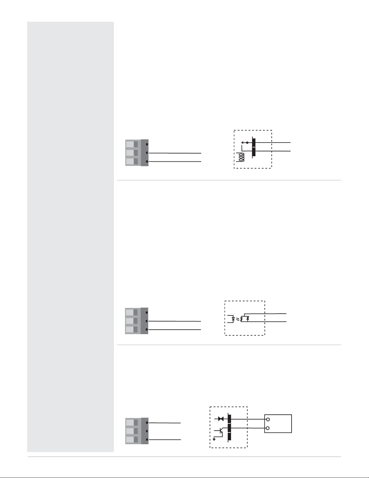
Figure 16a — Output 3 Mechanical Relay
PD_ _ - _ _ J _ - _ _ _ _
• Form A contact
• 2 A, resistive
• 125 VA pilot duty, 120/240VÅ (ac), inductive
• 240VÅ (ac) maximum
• 30VÎ (dc) maximum
• See Quencharc note
• For use with ac or dc
• Minimum load current: 10 mA
• Output does not supply power
Figure 16b — Output 3 Solid-state Relay
PD_ _ - _ _ K _ - _ _ _ _
• Form A.contact
• 0.5 A, resistive
• 20 VA pilot duty, 120/240VÅ (ac), inductive
• 24 to 240VÅ (ac)
• See Quencharc note
• Minimum load current 10 mA
• Maximum leakage current 100 µA
• Not for use with direct current (dc)
• Output does not supply power
Figure 16c — Output 3 Switched DC
PD_ _ - _ _ C _ - _ _ _ _
• Maximum supply current 30 mAÎ (dc)
• Supply voltage 24VÎ (dc)
• Not for switching mechanical relays
• Output supplies power
Mechanical Relay
19 20 21
20 com
21 normally open
Internal Circuitry
Solid-state Relay
19 20 21
20 com
21 normally open
Solid-state Switch
Internal Circuitry
20
21
20
21
COM.
N.O.
COM.
N.O.
19 20 21
19 DC +
20 com
Switched DC
24VÎ (dc)
dc+
dc-
19
21
+
-
Load
21 DC -
Internal Circuitry
Page 19
Watlow Series PD ■ 17 ■ Chapter 2 Install and Wire
ç
Warning:
Use National Electric (NEC) or
other country-specific standard
wiring and safety practices when
wiring and connecting this controller to a power source and to
electrical sensors or peripheral
devices. Failure to do so may result in damage to equipment and
property, and/or injury or loss of
life.
Quencharc Note:
Switching pilot duty loads (relay
coils, solenoids, etc.) with the
mechanical relay or solid-state
relay output options requires use
of an R.C. suppressor.
Watlow carries the R.C. suppressor Quencharc brand name,
which is a trademark of ITW
Paktron. Watlow Part No. 08040147-0000.
Note: A current transformer input
is not available for Output 1 or 3
if a process output.
Note: 24 VÅÅinput power required to use single cycle,variable time base output function.
Figure 17a — Output 3 Open Collector
PD_ _ - _ _ C _ - _ _ _ _
• Maximum current sink 200 mAÎ (dc)
• Maximum supply voltage 42VÎ (dc)
• Output does not supply power
Figure 17b — Output 3 Process
PD_ _ - _ _ F _ - _ _ _ _
• Analog output scalable from 0 to 10VÎ (dc) or 0 to 20 mAÎ (dc)
• Load capability: voltage, 1 kΩ minimum; current, 800 Ω maximum
• Output supplies power
• Cannot use voltage and current output at the same time
Figure 17c — Output 4 Mechanical Relay
PD_ _ - _ _ _ E - _ _ _ _
• Form C.contacts
• 2 A, resistive
• 125 VA pilot duty, 120/240VÅ (ac), inductive
• 240VÅ (ac) maximum
• 30VÎ (dc) maximum.
• See Quencharc note
• For use with ac or dc
• Minimum load current: 10 mA
• Output does not supply power
Class 2 power source
19 20 21
19 DC +
20 com
21 DC -
Open Collector
42VÎ (dc) maximum
dc+
dc-
COM.
Internal Circuitry
required for agency
compliance.
19
21
20
-
+
Load
Power
Supply
+
-
19 20 21
19 volts +
20 com 21 amps +
22 23 24
22 normally closed
23 com
24 normally open
Mechanical Relay
Internal Circuitry
N.C.
COM.
N.O.
22
23
24
Page 20
Watlow Series PD ■ 18 ■ Chapter 2 Install and Wire
ç
Warning:
Use National Electric (NEC) or
other country-specific standard
wiring and safety practices when
wiring and connecting this controller to a power source and to
electrical sensors or peripheral
devices. Failure to do so may result in damage to equipment and
property, and/or injury or loss of
life.
Quencharc Note:
Switching pilot duty loads (relay
coils, solenoids, etc.) with the
mechanical relay or solid-state
relay output options requires use
of an R.C. suppressor.
Watlow carries the R.C. suppressor Quencharc brand name,
which is a trademark of ITW
Paktron. Watlow Part No. 08040147-0000.
Note: 24 VÅÅinput power required to use single cycle,variable time base output function.
Figure 18a — Output 4 Solid-state Relay
PD_ _ - _ _ _ K - _ _ _ _
• Form A.contact
• 0.5 A, resistive
• 20 VA pilot duty, 120/240VÅ (ac), inductive
• 24 to 240VÅ (ac)
• See Quencharc note
• Minimum load current 10mA
• Maximum leakage current 100µA
• Not for use with direct current (dc)
• Output does not supply power
Figure 18b — Output 4 Switched DC
PD_ _ - _ _ _ C - _ _ _ _
• Maximum supply current 30 mAÎ (dc)
• Supply voltage 24VÎ (dc)
• Not recommended for switching mechanical relays
• Output supplies power
Figure 18c — Output 4 Open Collector
PD_ _ - _ _ _ C - _ _ _ _
• Maximum current sink 200 mAÎ (dc)
• Maximum supply voltage 42VÎ (dc)
• Output does not supply power
Solid-state Relay
Solid-state Switch
22 23 24
23 com
24 normally open
Internal Circuitry
Switched DC
24VÎ (dc)
dc+
22 23 24
22 dc +
23 com
24 dc -
Internal Circuitry
dc-
22
24
+
-
Load
23
24
COM.
N.O.
Open Collector
42VÎ (dc) maximum
22 23 24
22 dc +
23 com
24 dc -
Internal Circuitry
Class 2 power source
required for agency
compliance.
dc+
22
24
dc-
23
COM.
-
+
Load
Power
Supply
+
-
Page 21

Watlow Series PD ■ 19 ■ Chapter 3 Indicator Lights
The Series PD controller may have up to nine LED indicator lights to help you monitor the
status of input power, Ethernet functions, input errors and outputs status. These LEDs can
provide a quick visual indication of basic controller functions. An additional heartbeat LED,
used for diagnostics, can be seen through the top vent at the back left side of the controller.
Heartbeat LED Diagnostics:
• Application Mode (normal operation) - 1 flash per second
• Test Mode (internal factory calibration) - 10 flashes per second
• Boot Code (internal factory configuration) - 1 flash per 2 seconds
Both Input Error LEDs Lit
• TFTP Mode (flash download in progress)
Figure 18 — Series PD LED Indicator Lights
Indicator Lights
3
Heartbeat (diagnostics)
Green light can be seen on the left
side pc board, through the top vents
Power
Green light stays lit when the
power is on.
• If not lit or flashing, check
your power source.
Ethernet Link:
Green light is lit if the Ethernet
cable is correctly wired and
connected to a 10BaseT port.
• If not lit, check for the correct
RJ-45 cable and switch/hub speed.
Ethernet Activity
Green light is lit when communication activity occurs.
(1) Input Error
Red light is lit if there is a sensor
problem on Input 1. Lights momentarily after power up.
• If it stays lit:
- Verify the sensor wiring, polarity
and function.
- Rewire or replace as necessary.
(2) Input Error
Red light is lit if there is a sensor
problem on Input 2. Lights momentarily after power up.
• If it stays lit:
- Verify the sensor wiring, polarity
and function.
- Rewire or replace as necessary.
at the back of the unit.
(1) Output
Red light is lit or flashes when
control Output 1 is active. If it does
not light up, the output is not active.
The output may be configured as an
event (alarm) or control.
(2) Output
Red light is lit or flashes when
control Output 2 is active. If it does
not light up, the output is not active.
The output may be configured as an
event (alarm) or control.
(3) Output
Red light is lit or flashes when
control Output 3 is active. If it does
not light up, the output is not active.
The output may be configured as an
event (alarm) or control.
(4) Output
Red light is lit or flashes when
control Output 4 is active. If it does
not light up, the output is not active.
The output may be configured as an
event (alarm) or control.
Output
Output
Output
Output
PD
1
2
3
4
PID Controller
Power
Ethernet Link
Ethernet Activity
Input Error
1
2
Input Error
Address
Address Field
Record the unit's Device Name
in erasable marker here. For example,
PD012345.
Page 22

Watlow Series PD ■ 20 ■ Chapter 4 Ethernet Communications
Network security is a critical issue for any network. Be sure to work with your network administrator
to ensure that you follow best security practices to ensure a secure network environment. Here are some
items to consider when installing Ethernet based controls on any network.
• Use private IP addresses.
• Separate the process network(s) from business network(s).
• If external access is required, then have a single point of access to the process network.
• External access points should be protected by a firewall.
• External access points should be protected by a layer 3 switch or router.
• Access to the Internet should be indirect, going through an access point to the business
network on the way.
• Separate processes or cells using VLANs.
• Run virus protection software on all PC's on the process network.
Refer to the bottom of the web page navigation frame for the browser versions supported. You may access the Series PD and view controller parameters via an onboard Web (HTTP) server.
The Series PD supports full product configuration and monitoring of runtime parameters via MODBUS TCP over TCP/IP using a third party software package such as Lookout™, created and sold by National Instruments.
The 10BaseT Ethernet connection supports the TCP/IP stack. At the application layer it has an HTTP
(web) and Modbus server. The HTTP server provides a means of changing runtime parameters via
HTML. The TCP/IP stack supports DHCP client, Auto IP, Static IP, DNS client, and Netbios name
resolution.
Getting Started
1. Connect the Series PD to your computer's Ethernet port using a cross-wired RJ45 cable or connect the
Series PD to a switch/hub or network using a straight wired RJ45 Category 5 cable. The Series PD is
limited to a 10BaseT connection and will not work on an Ethernet port set for 100BaseT only. Use of a
10/100 switch/hub will overcome this issue if your PC has only a 100BaseT port.
2. Wire a 24V‡ (ac/dc) power supply to the Series PD power terminals. See wiring section.
3. Wire sensor inputs and controller outputs. See wiring section.
4. Power up the controller, switch/hub and PC.
5. Start your Internet browser. Enter the Browse at address of the Series PD into the browser’s address
field. See figure on next page for the Browse at address location on the left side label. Two different
Netbios names may be used to access the Series PD. Either PDxxxxxx, where xxxxxx is the first six
digits of the serial number, located on the left side label, or WATxxxxxx, where xxxxxx is the last six
digits of the Series PD MAC address. The MAC address is also printed on the left side label of the Series PD in the form xx:xx:xx:xx. See figure on next page.
Note: Browsing the Series PD using the Netbios name only works with Windows. The computer and Series PD must
be on the same logical network. Browsing using the IP address always works.
Note: If you are not using a DHCP server, it may take several minutes for both the Series PD and your computer to
get their IP addresses.
Ethernet Communications
4
Page 23

Figure 21 — Browse at address, MAC address, and Serial number locations
6. When you change data on the Monitor Device page or access other web pages, you are prompted to en-
ter a Network Security user name and password. The factory defaults are:
user name - new
password - user
7. Once you enter the user name and password you can access the other controller pages. If you browse
another address or close your browser, you will be required to enter this information again.
8. To change security level passwords, go to Device Configuration > Network > Security.
9. To configure the Series PD, go to Device Configuration and set up the unit.
Note: The controller leaves the factory with all inputs, outputs and control loops set to off.
Go through each Device Configuration page and make the appropriate selections for your application.
Click the Submit button at the bottom of each page.
Note: Be sure to click the Submit button at the bottom of any Device Configuration screen to send your changes to
the controller. Changes are not entered into the controller until you submit them.
9. Select the Monitor Device page. The process values and set points are displayed. You can change con-
troller set point and the mode of operation, auto or manual. Select the parameter value you want to
change by clicking on it, enter the new parameter value and click the Submit button. This sends the
Series PD the new value and refreshes the Monitor Device page.
Note: Information on the Monitor Device page, including alarms and errors, is automatically refreshed once per second, if your browser supports Java Virtual Machine and is enabled to allow Java applets to run.
Network Services
The Series PD supports DHCP client, Auto IP, and Static IP for address assignment. Normally you
will not need to make any changes. The user is able to configure preferences as to which services are used
if available. Intelligence is employed within the Series PD to revert to backup IP assignment methods if
the primary method is unavailable. It will try DHCP first, then Auto IP to assign an IP address. This is
the same method that a Windows based computer uses to get an IP address.
When using Auto IP, the Series PD starts with the IP address 169.254.10.10. If this address is already
in use, it will randomly attempt other addresses in the 169.254.XX.XX subnet. As with any IP networking
device, the IP address assigned to the Series PD must be compatible with the network it is physically connected to.
Note: If you are using Auto IP, it may take several minutes for both the Series PD and your computer to get their IP
addresses.
The Series PD does support DNS client and Netbios name resolution. Configuration information may
be entered at the Network Display Setup page.
Note: If you forget the fixed IP address of your Series PD, short the jumper connections on the top of the unit (see page 5), turn
the input power off and back on again. This causes the Series PD to use DHCP first, AutoIP and finally fixed IP addressing to try
assigning an IP address. This allows you to read the current fixed IP address. Once the unit is powered up without the jumper
connections shorted, the Series PD returns to using the previous IP addressing settings.
PDxx-xxxx-xxxx
Watlow Series PD ■ 21 ■ Chapter 4 Ethernet Communications
Serial number
Type PD012345
Browse at address
Type PD012345
Auxiliary Inputs
1.
2.
3.
4.
Input 2
5.
6.
7.
8.
Input 1
9. TC-/S3/V-/I-
10. TC+/S1
11. I+/S2
12. V+/Info.Data
W
O
L
T
A
onnectivity
W
-solutions
Browse at:
http://PD012345
Made In USA
DC: YYWWSN: 012345
00:01:23:45:67:89
MAC Address:
MAC Address
Type WAT456789
Page 24
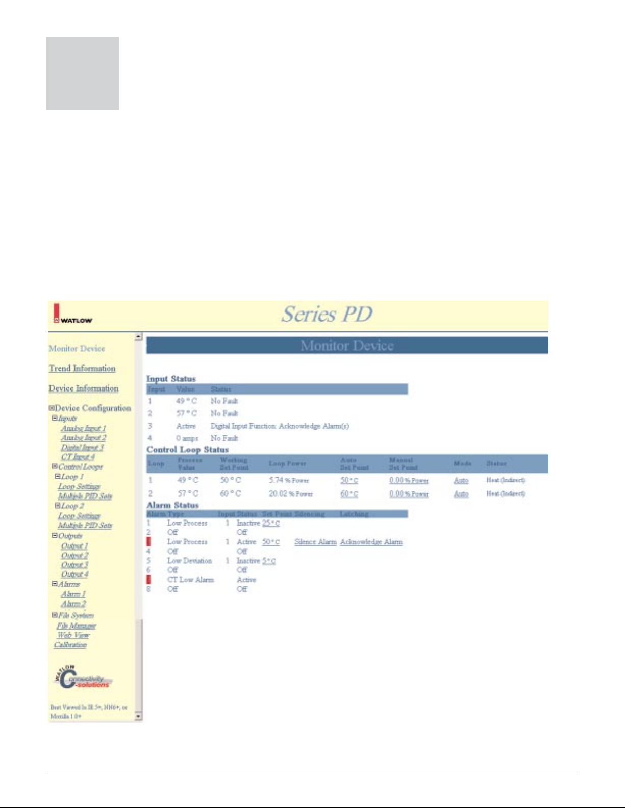
Watlow Series PD ■ 22 ■ Chapter 5 Monitor Device Page
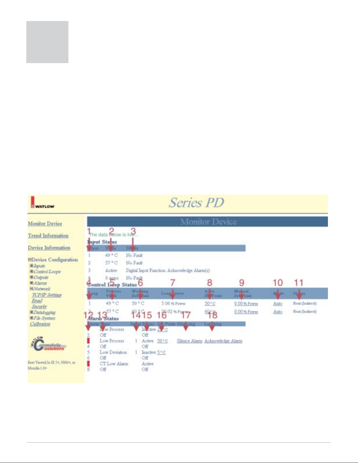
When accessing a Series PD controller through a browser, the Monitor Device page appears. The Monitor Device page contains real-time information representing the current process conditions. This information is loaded
when the Monitor Device page is browsed and is automatically refreshed once every second. The Monitor Device
page provides real-time information on:
• Input Status
• Control Loop Status
• Alarm Status.
Input errors and alarms appear on this page as a red box next to the related input or output. These are refreshed once a second.
If you try to change any values on the Monitor Device page, you are prompted to enter Network Password
information. The User Name is new and Password is user. Be sure to change your user name and password if
controller security is a concern. If you want your browser to remember the User Name and Password after you
enter it the first time, check the box, Save this password in your password list. If you close your browser, you
must re-enter your user name and password information.
Note: You must have Java Virtual Machine installed on your computer and Java must be enabled for the Monitor Device page to display
properly in your browser. Most browsers will already have this configured by default.
Figure 22 — Monitor Device Web Page Example
Note: Red tag arrows and tag numbers are links to item descriptions. Click on a red tag arrow or number to go to a description of the item.
Monitor Device Page
5
Page 25
Watlow Series PD ■ 23 ■ Chapter 5 Monitor Device Page
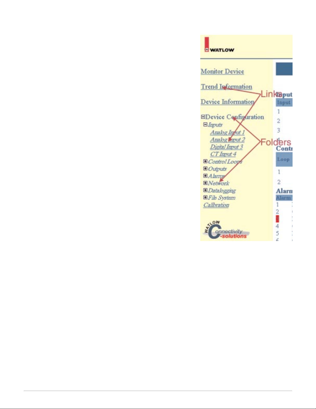
Navigation Frame
The left side of the Series PD web pages contain a navigation frame
that looks and operates much like Windows Explorer™. This frame does
not change as web pages are accessed and changed. The navigation area
contains folders and web page links. A plus (+) sign in front of a folder
indicates the folder can be expanded to show more information. A minus
(-) sign in front of a folder indicates the folder can be contracted to show
less information.
For example, if you click on the + sign in front of the Device Configuration folder or click on the Device Configuration folder itself, you expand the Device Configuration folder. The folders that appear contain
additional folders as indicated by the + sign in front of each folder. Click
on the + or - sign in front of any folder or click on the folder itself to expand or contract that folder.
When you see page links (underlined text), you can click on a link to
take you to a specific Series PD web page. For example, with the Inputs
folder expanded, click on the Analog Input 1 link to go to the Analog Input 1 Configuration page.
Figure 23 — Navigation Frame Example
Page 26

Watlow Series PD ■ 24 ■ Chapter 5 Monitor Device Page
Figure 24 — Monitor Device Web Page Tag Descriptions
Tag # Monitor Device Page Parameters Parameter Description
Input Status
1. Input Number Identifies input hardware that is installed. Red box appears for
any input that is in a fault condition.
2. Input Value Actual analog input value for Inputs 1 and 2.
Digital Input condition or Current Transformer input value for
Inputs 3 and 4.
3. Input Status Input error status for analog, digital or current transformer inputs.
Control Loop Status
4. Control Loop Number Identifies control loop hardware that is installed. Loop 2 appears
only on dual loop models.
5. Control Loop Process Value Actual analog input value for the control loop(s). Active analog
inputs can be assigned to either control loop.
6. Control Loop Working Set Point Active set point. Could be one of several set point sources, Auto
Set Point, Digital Set Point, or Ramp to Set Point
7. Control Loop Power Actual ouput power level for each control loop.
8. Control Loop Auto Set Point Automatic mode (closed loop) set point. Click on the desired loop
set point, enter the new Auto Set Point value in the pop up window and click Submit. The page refreshes and displays the new
Monitor Device page data.
9. Control Loop Manual Set Point Manual mode (open loop, % power) set point. Click on the desired
loop manual set point, enter the new Manual Set Point value in
the pop up window and click Submit. The page refreshes and displays the new Monitor Device page data.
10. Control Loop Mode Loop control mode. Automatic mode (closed loop control), Manual
mode (open loop control) or Off (loop disabled).
11. Control Loop Status Control loop output function. Heat, Cool, Heat/Cool or Off (dis-
abled) output operation.
Alarm Status
12. Alarm Number Identifies alarms. Red box appears for any alarm that is active.
13. Alarm Type Deviation Alarm, Process Alarm or Off (disabled).
14. Alarm Input Analog input assigned to the alarm.
15. Alarm Status Indicates if an alarm is inactive, active or off (disabled). Red box
appears in Alarm Number column when alarm is active
16. Alarm Set Point Trip point for the alarm. Click on the desired alarm set point, en-
ter the new Alarm Set Point value in the pop up window and click
Submit. The page refreshes and displays the new Monitor Device
page data.
17. Alarm Silencing If enabled, the alarm output can be disabled. A Silence Alarm link
appears on the Monitor Device page when the alarm trips. Click
this link to disable the alarm output.
18. Alarm Latching If enabled, the alarm output latches when tripped. An Acknowl-
edge link appears on the Monitor Device page when the alarm
trips. Once the process returns to the safe region, click this button
to reset the latched alarm output.
Page 27
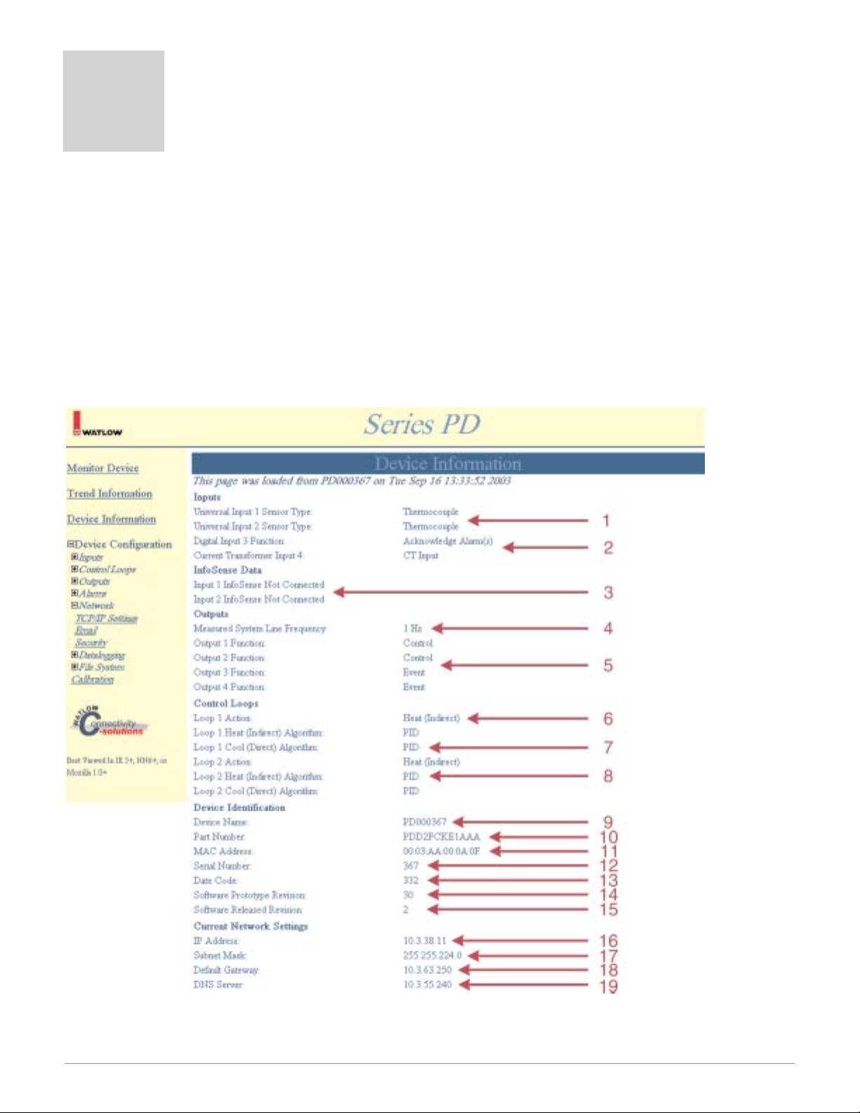
Watlow Series PD ■ 25 ■ Chapter 6 Device Information
The Device Information page provides important information about the Series PD controller. Information on the
controller hardware, its configuration and network settings can be easily accessed from this page. The time and
date the page was loaded appears at the top of the page. This page is not automatically refreshed. The Device Information page provides information on:
• Inputs
• INFOSENSE™ Data
• Outputs
•Control Loops
• Device Identification
• Current Network Settings
Note: If you are going to Restore Factory Defaults or Restore User Settings, we strongly recommend that you document all of your settings
first. Be sure to document your Current Network Setttings, found at the bottom of the Device Information page.
Figure 25 — Device Information Web Page Example
Note: Red tag arrows and tag numbers are links to item descriptions. Click on a red tag arrow or number to go to a description of the item.
Device Information Page
6
Page 28

Watlow Series PD ■ 26 ■ Chapter 6 Device Information
Figure 26 — Device Information Web Page Tag Descriptions
Tag # Device Information
Configuration Parameters
Section Description
Inputs
1. Universal Input Sensor Type Displays what input hardware is present and input configuration
information. Inputs 1 and 2 are universal analog inputs and will
accept a wide variety of input signals. Input 2 is an ordering option. See model number information
2. Digital Input Function
Current Transformer Input
Inputs 3 and 4 can be ordered as digital or current transformer inputs. See model number information.
Digital Input Function - displays what action is taken when the
digital input condition is satisfied.
Current Transformer Input - displays what CT hardware is present and enabled.
INFOSENSE
3. INFOSENSE Data Displays specific sensor data when connected to an INFOSENSE
sensor. The part number, serial number and calibration date information is retrieved from the INFOSENSE sensor.
4. Measured System
Line Frequency
Displays system power line frequency. If correct frequency is not
detected, single cycle burst firing mode not available. See Features
chapter.
Outputs
5. Output 1-4 Displays what output hardware is present and output configura-
tion information.
Control Loops
6. Loop Action Displays control loop action; heat, cool, heat/cool or off (disabled).
7. Loop Cool Algorithm Displays control loop cool algorithm selected, On/Off or PID.
8. Loop Heat Algorithm Displays control loop heat algorithm selected, On/Off or PID.
Device Identification
9. Device Name Displays the assigned Netbios name. The default device name is
PDXXXXXX, where XXXXXX is the serial number. This name can
be changed on the TCP/IP Settings page in the Network folder.
Not all computer networking configurations support Netbios
names.
10. Part Number Displays the Series PD model number.
11. MAC Address Displays the assigned MAC address. You can also use the MAC
address as another Netbios name to browse the Series PD by using WATXXXXXX, where XXXXXX are the last six digits of the
MAC address without colons. Not all computer networking configurations support Netbios names.
Page 29

Watlow Series PD ■ 27 ■ Chapter 6 Device Information
Figure 27 — Device Information Web Page Tag Descriptions (continued)
Tag # Device Information
Configuration Parameters
Section Description
12. Serial Number Displays the Series PD serial number.
13. Date Code Displays the date the unit was manufactured. The format is year
week. For example, 345 would be 2003, 45th week.
14. Software Prototype Revision Displays firmware prototype revision.
15. Software Released Revision Displays firmware release revision.
Current Network Settings
16. IP Address Displays IP address number. Series PD supports DHCP client,
autoIP and fixed IP address assignment.
17. Subnet Mask Displays current subnet mask.
18. Default Gateway Displays current default gateway.
19. DNS Server Displays current DNS server.
Page 30
Watlow Series PD ■ 28 ■ Chapter 7 Configuration Page
The Device Configuration page contains folders and links for configuring the Series PD. The controller leaves
the factory with default settings that disable most input and output functions. To get the Series PD operational,
you must go through the Device Configuration folders and set up the controller. The Device Configuration folders
are:
• Inputs
•Control Loops
• Outputs
• Alarms
• Network
• Datalogging
• File System
Note: You may not see all of the Device Configuration page folders listed above. Your model number determines what folders appear.
Figure 28 — Device Configuration Navigation Frame Expanded Example
Device Configuration Page
7
Page 31

Watlow Series PD ■ 29 ■ Chapter 7 Configuration Page
Inputs
The Inputs folder contains links for configuring the inputs installed in the Series PD. The controller leaves the
factory with default settings that disable all input functions. To get the Series PD operational, you must go through
the Inputs links and set up the controller inputs. The Inputs folder links are:
• Analog Input 1
• Analog Input 2 (dual channel model only)
• Digital Input 3 or 4
• Current Transformer Input 3 or 4
Note: You may not see all of the Inputs folder links listed above. Your model number determines what input parameters appear.
Analog Input Configuration Page
Inputs 1 and 2 are analog inputs. Analog inputs are used to measure process variables like temperature, humid-
ity, pressure, flow, level, etc. The universal analog inputs accept most common thermocouple types, 100Ω Platinum
RTD (DIN curve) and process input signals. Input 2 only appears on dual channel models.
You can see and change all of the parameters on the Analog Input Configuration page. Only those that apply to
the sensor type selected will be relevant. For example, you can set all of the process parameters even though you
have thermocouple enabled. Only parameters relating to thermocouples have any effect on the controller. If you
change the sensor type to process, those process parameter values previously entered are used.
Note: You must click Submit to send the new values to the Series PD.
Figure 29 — Analog Input Configuration Web Page Example
Note: Red tag arrows and tag numbers are links to item descriptions. Click on a red tag arrow or number to go to a description of the item.
Page 32

Watlow Series PD ■ 30 ■ Chapter 7 Configuration Page
Figure 30 — Analog Input Web Page Tag Descriptions
Tag # Analog Input
Configuration Parameters
Parameter Description
Analog Input
1. Sensor Type Selects the analog input sensor type. Off (disabled), thermocouple,
RTD, voltage process, current process or INFOSENSE PnP
Thermocouple Parameters
2. Thermocouple Type Selects the analog input thermocouple linearization. Type J, K, B,
T, E, N, C, D, PTII, R or S.
RTD Parameters
3. RTD Curve Sets the RTD calibration curve. DIN curve only.
Process Parameters
4. Process Precision Sets the decimal position for the process input. 0, 0.0, 0.00 or
0.000.
5. Process Units Selects the units label displayed on the web page. Up to four al-
pha- numeric characters.
6. Low Process Scale Sets the low scale value for the process input signal. For example,
if you want 4-20 mA to represent 0 to 100%RH, set low process
scale to 0.
7. High Process Scale Sets the high scale value for the process input signal. For exam-
ple, if you want 4-20 mA to represent 0 to 100%RH, set high
process scale to 100.
8. Low Voltage Scale Sets the low range value for the voltage input signal. For example,
if you need 1-5 Vdc, set low voltage scale to 1.
9. High Voltage Scale Sets the high range value for the voltage input signal. For exam-
ple, if you need 1-5 Vdc, set high voltage scale to 5.
10. Low Current Scale Sets the low range value for the current input signal. For exam-
ple, if you need 4-20 mA, set low current scale to 4.
11. High Current Scale Sets the high range value for the current input signal. For exam-
ple, if you need 4-20 mA, set high current scale to 20.
Temperature Process Value Configuration
12. Temperature Process
Value Units
Sets the temperature measurement units. Celcius or Fahrenheit.
13. Temperature Process
Value Precision
Selects the decimal location for temperature inputs. 0 or 0.0.
Input Filtering
14. Filter Method Selects the filtering action for the input signal. Off (disabled) or
First Order.
15. Filter Time Base Sets the time constant for the first order filter. 0.1 to 60.0 seconds.
Offsets
16. Single Offset Value Shifts the input signal up or down.
Page 33

Watlow Series PD ■ 31 ■ Chapter 7 Configuration Page
Digital Input Configuration Page
Inputs 3 and 4 can be ordered as digital inputs. The digital input accepts a contact closure or a dc voltage input,
and performs some function based upon the digital event input status. For example, when the digital event input is
low, switch to a different auto set point value. If the digital event input goes back high, switch back to the original
control auto set point value. See Features chapter.
You can see and change all of the parameters on the Digital Input Configuration page. Only those that apply to
the function selected will be relevant. For example, you can set all of the Acknowledge Alarm parameters even
though you have Switch to Digital Set Point enabled. Only parameters relating to Switch to Digital Set Point have
any effect on the controller. If you change the function to Acknowledge Alarms, those alarm related parameters
previously entered are used.
Note: You must click Submit to send the new values to the Series PD.
Figure 31 — Digital Input Configuration Web Page Example
Note: Red tag arrows and tag numbers are links to item descriptions. Click on a red tag arrow or number to go to a description of the item.
Page 34

Watlow Series PD ■ 32 ■ Chapter 7 Configuration Page
Figure 32 — Digital Input Web Page Tag Descriptions
Tag # Digital Input
Configuration Parameters
Parameter Description
1. Function Selects the digital input function when the digital input active
condition is satisfied. Off (disabled), Switch to Digital Set Point,
Acknowledge Alarm(s), Switch to Manual Control, Switch Control
Loop Off or Pause Data Logging.
2. Active State Selects the type of signal change required to trigger the digital in-
put. Low/Falling Edge or High/Rising Edge.
Acknowledge Alarm
3. Alarm Action Selects the alarm actions to be taken when the digital input active
state is satisfied. Silence, Acknowledge or Silence and Acknowledge.
4. Which Alarms Sets the alarms that are affected by the alarm action setting.
Alarm 1 through Alarm 8.
Switch to Manual Control
5. Which Loops Sets the Control Loop that switches to Manual Control when the
digital input active state is satisfied. Loop 1 or Loop 2.
Switch Control Loop Off
6. Which Loops Sets the Control Loop that switches to Off (disabled) when the
digital input active state is satisfied. Loop 1 or Loop 2.
Digital Set Point
7. Which Loop Sets the Control Loop that switches to the Digital Set Point when
the digital input active state is satisfied. Loop 1 or Loop 2.
8. Digital Set Point Sets the Digital Set Point used when the digital input active state
is satisfied. Value must be within the set point range limits.
Page 35
Watlow Series PD ■ 33 ■ Chapter 7 Configuration Page
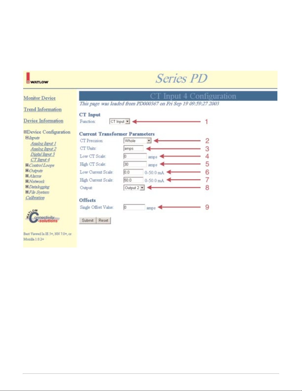
CT (current transformer) Input Configuration Page
The CT input accepts a signal from a CT monitoring heater current. The CT develops an output signal proportional to the current flowing through the wire passing through the center hole of the CT. You can assign one or
more alarm outputs to any CT input. The alarm can be configured to trip if the heater current gets too low or too
high. The CT input cannot be used with a process output. See Features chapter.
Note: You must click Submit to send the new values to the Series PD.
Figure 33 — CT(current transformer) Input Configuration Web Page Example
Note: Red tag arrows and tag numbers are links to item descriptions. Click on a red tag arrow or number to go to a description of the item.
Page 36

Watlow Series PD ■ 34 ■ Chapter 7 Configuration Page
Figure 34 — CT Input Web Page Tag Descriptions
Tag # CT Input
Configuration Parameters
Parameter Description
CT Input
1. Function Turn the CT input on or off.
Current Transformer Parameters
2. CT Precision Selects the decimal position for the CT input. 0, 0.0, 0.00 or 0.000.
3. CT Units Selects the CT units label displayed on the web page. Up to four
alphanumeric characters.
4. Low CT Scale Sets the low value displayed with the minimum input signal.
-30000 to 30000.
5. High CT Scale Sets the high value displayed with the maximum input signal.
-30000 to 30000.
6. Low Current Scale Sets the minimum input signal value from the CT. 0.0 to 50.0.
7. High Current Scale Sets the maximum input signal value from the CT. 0.0 to 50.0.
8. Output Selects the output being monitored by the CT. Any output type,
except a process output, can be assigned to a CT input. Mimimum
on time required for valid CT readings. See Features chapter.
Offsets
9. Single Offset Value Sets the offset value for the CT input signal. -9999 to 9999.
Page 37

Watlow Series PD ■ 35 ■ Chapter 7 Configuration Page
Control Loops
The Control Loops folder contains folders and links for configuring the control loops installed in the Series PD.
The controller leaves the factory with default settings on the Loop Setting page that disable all output functions. To
get the Series PD operational, you must go through the Loop Settings links and set up the control loops. The Loop
folder links are:
• Loop Settings
• Multiple PID Sets
Note: Loop 2 folder appears on dual channel models only.
Loop Settings
The Control Loop Configuration page sets the parameters for the control loops installed. The control loop functions, input failure parameters, set point limits, on/off parameters, autotune start/stop, PID parameters and ramp
to set point settings are configured on this page.
You can see and change all of the parameters on the Control Loop Configuration page. Only those that apply
will be relevant. For example, you can set the On/Off Hysteresis even though you have the Loop Algorithms set to
PID control. Only parameters relating to PID have any effect on the controller. If you change the Loop Algorithm to
On/Off, the hysteresis values previously entered are used.
Note: You must click Submit to send the new values to the Series PD.
Figure 35 — Control Loop Configuration Web Page Example
Note: Red tag arrows and tag numbers are links to item descriptions. Click on a red tag arrow or number to go to a description of the item.
Page 38

Watlow Series PD ■ 36 ■ Chapter 7 Configuration Page
Figure 36 — Control Loop Web Page Tag Descriptions
Tag # Control Loop
Configuration Parameters
Parameter Description
Control Loop
1. Loop Action Sets the Control Loop output action Off (disabled), heat, cool or
heat/cool.
2. Loop Heat (indirect) Algorithm Sets the Heat output method of control. PID or On/Off.
3. Loop Cool (direct) Algorithm Sets the Cool output method of control. PID or On/Off.
Input Failure Parameters
4. Failure Latching Sets the input sensor failure latching action. Latching or Non-
latching.
5. Output transition from
Auto Mode to:
Selects the controller’s output mode upon input failure. Off (disabled), Bumpless Power or Fixed Power.
6. Failure Fixed Power Sets the fixed output power level for fixed output power level upon
input failure. -100 to 100%.
Set Point Limits
7. Low Limit Sets the minimum value for auto set point adjustment. Range de-
pends upon sensor selected.
8. High Limit Sets the maximum value for auto set point adjustment. Range de-
pends upon sensor selected.
On/Off Parameters
9. Hysteresis Heat (indirect) Sets the switching differential when configured as On/Off method
of control.
10. Hysteresis Cool (direct) Sets the switching differential when configured as On/Off method
of control.
PID Parameters
11. Start Autotune Start an autotune.
12. Autotune Set Point Sets the autotune set point as a percentage of the auto set point.
50 to 150%.
13. PID Sets Sets the PID capability for single or multiple PID sets.
14. PID Set 1, Proportional Band Sets proportional band value for PID Set 1.
15. PID Set 1, Integral Sets integral value for PID Set 1.
16. PID Set 1, Derivative Sets derivative value for PID Set 1.
17. PID Set 1, Dead Band Sets dead band value for PID Set 1.
Ramp to Set Point Parameters
18. Ramp Action Selects the ramp to set point action for the single set point ramp
function. Off (disabled), Ramp on Power Up, Ramp on Set Point
Change, or Ramp on Power Up and Set Point Change.
19. Ramp Rate Sets the ramp rate for the ramp to set point function.
20. Ramp Rate Time Units Sets the ramp rate time units for the ramp to set point function.
Ramp time in degrees/units per hour or per minute.
Page 39

Watlow Series PD ■ 37 ■ Chapter 7 Configuration Page
Multiple PID Loop Configuration
The Multiple PID Loop Configuration page allows access to all of the PID sets for each loop available. You can
see and change all of the parameters on the Multiple PID Loop Configuration page, but only those that apply will
be relevant.
For example, you can set the Cool PID values even though the Series PD is set for heat PID control. Only parameters relating to heat PID values have any effect on the controller. If you change the Loop Action to Heat/Cool,
the cool PID values previously entered are used.
Note: Multiple PID Loop 2 Configuration appears on dual channel models only.
Note: You must click Submit to send the new values to the Series PD.
Figure 37 — Multiple PID Loop Configuration Web Page Example
Note: Red tag arrows and tag numbers are links to item descriptions. Click on a red tag arrow or number to go to a description of the item.
Page 40

Watlow Series PD ■ 38 ■ Chapter 7 Configuration Page
Figure 38 — Multiple PID Loop Web Page Tag Descriptions
Tag # Multiple PID Loop
Configuration Parameters
Parameter Description
1. Cross Over Source Sets the source that triggers switching PID sets. Process or Set
Point.
PID Set No. 1 - Prop Band
2. Heat (indirect) Sets the proportional band value for the heat outputs.
3. Cool (direct) Sets the proportional band value for the cool outputs.
PID Set No. 1 - Integral
4. Heat (indirect) Sets the integral value for the heat outputs.
5. Cool (direct) Sets the integral value for the cool outputs.
PID Set No. 1 - Derivative
6. Heat (indirect) Sets the derivative value for the heat outputs.
7. Cool (direct) Sets the derivative value for the cool outputs.
PID Set No. 1 - Dead Band
8. Heat (indirect) Sets the offset value of the heating proportional band from the set
point.
9. Cool (direct) Sets the offset value of the cooling proportional band from the set
point.
PID Set No. 1 - Cross Over Point
10. Cross Over Point Sets the process or set point value where the PID sets cross over.
Greater than or equal to this value activates this PID set. Must be
within set point range limits.
Page 41

Watlow Series PD ■ 39 ■ Chapter 7 Configuration Page
Outputs
The Outputs folder contains links for configuring the outputs installed in the Series PD. The controller leaves
the factory with default settings on the Output pages that disable all output functions. To get the Series PD operational, you must go through the Output links and set up the outputs. The Outputs folder links are:
• Outputs 1
• Outputs 2
• Outputs 3
• Outputs 4
Process Output Configuration Page
The Process Output Configuration pages set the parameters for the process outputs installed. Outputs can be
configured as control outputs, event (alarm) outputs or retransmit outputs. The Process Output Configuration page
is shown below.
You can see and change all of the parameters on the Output Configuration page. Only those that apply will be
relevant. For example, you can set the Retransmit Parameters even though you have the Control Function set to
Control. Only parameters relating to control outputs have any effect on the controller. If you change the Output
Function to Retransmit, the Retransmit Parameters previously entered are used.
Note: You must click Submit to send the new values to the Series PD.
Figure 39 — Process Output Configuration Web Page Example
Note: Red tag arrows and tag numbers are links to item descriptions. Click on a red tag arrow or number to go to a description of the item.
Page 42

Watlow Series PD ■ 40 ■ Chapter 7 Configuration Page
Figure 40 — Process Output Configuration Web Page Tag Descriptions
Tag # Process Output
Configuration Parameters
Parameter Description
Output
1. Function Selects the output function. Off (disabled), Control, Event or
Retransmit
Control Output Parameters
2. Output Direction Selects the output direction. Off (disabled), Heat or Cool
3. Loop Selects the control loop assigned to that output. Loop 1 or Loop 2.
Loop 2 available on dual channel model only.
4. Low Power Scale Sets the minimum output power level available for the output. 0 to
100%.
5. High Power Scale Sets the maximum output power level available for the output. 0 to
100%.
Process Parameters
6. Analog Signal Selects the type of analog signal for the output. Voltage or Current.
7. Low Voltage Scale Sets the minimum value for the voltage signal scaling. For exam-
ple, if you want a 1-5 Vdc signal, set Low Voltage Scale to 1.
8. High Voltage Scale Sets the maximum value for the voltage signal scaling. For exam-
ple, if you want a 1-5 Vdc signal, set Low Voltage Scale to 5.
9. Low Current Scale Sets the minimum value for the current signal scaling. For exam-
ple, if you want a 4-20 mA signal, set Low Current Scale to 4.
10. High Current Scale Sets the maximum value for the current signal scaling. For exam-
ple, if you want a 4-20 mA signal, set High Current Scale to 20.
Retransmit Parameters
11. Source Selects what variable is represented by the retransmit signal.
Process 1, Set Point 1, Process 2 or Set Point 2. Loop 2 parameters
available on dual channel model only.
12. Scale Low Sets the value represented by the low voltage or current scale. For
example, if you want a 1-5 Vdc signal to represent 30° to 100°C, set
Scale Low to 30.
13. Scale High Sets the value represented by the high voltage or current scale. For
example, if you want a 1-5 Vdc signal to represent 30° to 100°C, set
Scale High to 100.
14. Offset Shifts the retransmit output signal up or down.
Event Output Parameters
15. Output Source Selects what sources are assigned as inputs to the logic function.
All alarm outputs and any digital inputs are available as input
sources.
16. Output Logic Selects the logic function applied to the alarms and digital inputs
selected. AND or OR logic.
17. Output Active State Selects the output state when the output is active. Energized or
De-engergized.
Page 43

Watlow Series PD ■ 41 ■ Chapter 7 Configuration Page
Time Proportioned Output Configuration
The Time Proportioned Output Configuration page sets the parameters for the time proportioned outputs installed. Outputs can be configured as control outputs or event (alarm) outputs. A time proportioned output cycles
on and off. The time the output is on versus off The Time Proportioned Output Configuration page is shown below.
You can see and change all of the parameters on the Output Configuration page. Only those that apply will be
relevant. For example, you can set the Event Output Parameters even though you have the Output Function set to
Control. Only parameters relating to control outputs have any effect on the controller. If you change the Output
Function to Event, the Event Output Parameters previously entered are used.
Note: You must click Submit to send the new values to the Series PD.
Figure 41 — Time Proportioned Output Configuration Web Page Example
Note: Red tag arrows and tag numbers are links to item descriptions. Click on a red tag arrow or number to go to a description of the item.
Page 44

Watlow Series PD ■ 42 ■ Chapter 7 Configuration Page
Figure 42 — Time Proportioned Output Configuration Web Page Tag Descriptions
Tag # Time Proportioned Output
Configuration Parameters
Parameter Description
Output
1. Function Selects the output function. Off (disabled), Control, Event or
Retransmit
Control Output Parameters
2. Output Direction Selects the output direction. Off (disabled), Heat or Cool
3. Loop Selects the control loop assigned to that output. Loop 1 or Loop 2.
(Loop 2 available on dual channel model only)
4. Output Cycle Time Sets the time base used for fixed time base mode of operation.
5. Output Mode Time Base Selects the output mode of operation. Fixed time base, Variable
time base or Single Cycle (only available with AC input power
source).
6. System Line Frequency Selects the line frequency of the AC input power. 50 or 60 Hz.
7. Low Power Scale Sets the minimum output power level available for the output. 0 to
100%.
8. High Power Scale Sets the maximum output power level available for the output. 0
to 100%.
Event Output Parameters
9. Output Source Selects what sources are assigned as inputs to the logic function.
All alarm outputs and any digital inputs are available as input
sources.
10. Output Logic Selects the logic function applied to the alarms and digital inputs
selected. AND or OR logic.
11. Output Active State Selects the output state when the output is active. Energized or
De-engergized.
Page 45

Watlow Series PD ■ 43 ■ Chapter 7 Configuration Page
Alarms
The Alarms folder contains links for configuring the eight alarms available on the Series PD. The controller
leaves the factory with default settings on the Alarms Configuration page that disable all alarm functions. To get
the Series PD alarms operational, you must go through the Alarms links and set them up. The Alarms folder links
are:
• Alarm 1 thru Alarm 8
Alarm Configuration Page
The Alarm Configuration pages set up the alarm functions. Alarms can be configured as process, deviation or
current alarms. The Series PD can also be configured to send out an e-mail when an alarm occurs.
You can see and change all of the parameters on the Alarm Configuration page. Only those that apply will be
relevant. For example, you can set the Deviation Alarm Parameters even though you have the Alarm Type set to
Low Process. Only parameters relating to the Process Alarm have any effect on the controller. If you change the
Alarm Type to High Deviation, the Deviation Alarm Parameters previously entered are used.
Note: You must click Submit to send the new values to the Series PD.
Figure 43 — Alarm Configuration Web Page Example
Note: Red tag arrows and tag numbers are links to item descriptions. Click on a red tag arrow or number to go to a description of the item.
Page 46

Watlow Series PD ■ 44 ■ Chapter 7 Configuration Page
Figure 44 — Alarm Configuration Web Page Tag Descriptions
Tag # Alarm Configuration
Parameters
Parameter Description
Alarm
1. Type Selects the type of alarm. Off (disabled), Low Process, High
Process, Low Deviation, High Deviation, CT Low Alarm or CT
High Alarm.
Process Alarm Parameters
2. Process Alarm Source Selects the input assigned to the process alarm. Process Value 1 or
Process Value 2. Loop 2 available on dual channel model only.
3. Process Alarm Set Point Sets the value at which the alarm is triggered.
Deviation Alarm Parameters
4. Deviation from Loop Set Point Selects the Loop the deviation set point is based on. Loop 1 or
Loop 2. Loop 2 available on dual channel model only.
5. Deviation Alarm Set Point Sets the value at which the alarm is triggered.
Current Transformer Alarm Parameters
6. Measurement Selects the source of the current transformer measurement. CT
Input 3 or CT Input 4.
7. Alarm Set Point Sets the value at which the alarm is triggered.
Alarm Email Parameters
8. Send Email Selects if an email gets sent when the alarm is triggered. No or
Yes.
9. Email Subject Sets the text message displayed in the subject line of the alarm
email. Enter up to 30 alphanumeric characters.
Alarm Email Parameters
10. Alarm Hysteresis Sets the switching differential for the alarm output.
11. Latching Selects if alarm latching is enabled. No or Yes.
12. Silencing Selects if alarm silencing is enabled. No or Yes.
13. Blocking Selects if alarm blocking is enabled. No or Yes.
Page 47

Watlow Series PD ■ 45 ■ Chapter 7 Configuration Page
Network
The Network folder contains links for configuring the network settings. The Network folder links are:
• TCP/IP Settings
• Email
• Security
Network Configuration Page
The Network Configuration page provides access to important information about your network and Series PD
network settings. Be sure to work with your network administrator when configuring the Series PD to operate on
your network.
Note: You must click Submit to send the new values to the Series PD.
Figure 45 — Network Configuration Web Page Example
Note: Red tag arrows and tag numbers are links to item descriptions. Click on a red tag arrow or number to go to a description of the item.
Page 48

Watlow Series PD ■ 46 ■ Chapter 7 Configuration Page
Figure 46 — Network Configuration Web Page Tag Descriptions
Tag # Network Configuration
Parameters
Parameter Description
Device Identification
1. Name Sets the Netbios name.Enter up to 15 alphanumeric characters.
Valid characters are: 0-9, A-Z, a-z, and “-”. The default device name
is PDXXXXXX, where XXXXXX is the serial number. Not all computer networking configurations support Netbios names.
Current Settings
2. IP Address Displays current IP address number. Series PD supports DHCP
client, AutoIP and Fixed IP address assignment.
3. Subnet Mask Displays current subnet mask.
4. Default Gateway Displays current default gateway.
5. DNS Server Displays current DNS server.
IP Address Resolution Method
6. Try DHCP, AutoIP, then Fixed IP Sets the IP address resolution method to try DHCP first. If unsuc-
cessful, try AutoIP next and finally Fixed IP to get an IP address.
7. Try DHCP, then Fixed IP Sets the IP address resolution method to try DHCP first. If unsuc-
cessful, try Fixed IP to get an IP address.
8. Try AutoIP, then Fixed IP Sets the IP address resolution method to try AutoIP first. If unsuc-
cessful, try Fixed IP to get an IP address.
9. Fixed IP Sets the IP address resolution method to Fixed IP to get an IP
address.
Fixed IP Address
10. Fixed IP Fixed IP address, if entered.
11. Subnet Mask Fixed subnet mask, if entered.
12. Default Gateway Fixed default gateway, if entered.
13. Fixed DNS Server Fixed DNS server, if entered.
Page 49

Watlow Series PD ■ 47 ■ Chapter 7 Configuration Page
Email Configuration Page
The Email Configuration page sets up the email capabilities for the Series PD. Alarms can be configured to send
out an email when the alarm trips. Be sure to work with your network administrator when configuring the Series
PD email functions to operate on your network..
Note: You must click Submit to send the new values to the Series PD.
Figure 47 — Email Configuration Web Page Example
Note: Red tag arrows and tag numbers are links to item descriptions. Click on a red tag arrow or number to go to a description of the item.
Page 50

Watlow Series PD ■ 48 ■ Chapter 7 Configuration Page
Figure 48 — Email Configuration Web Page Tag Descriptions
Tag # Email Configuration
Parameters
Parameter Description
Electronic Notification
1. SMTP Server IP Resolution Selects the method of SMTP server IP address resolution. Get
Server IP from Server Name or Fixed Server Address.
2. SMTP Server Name Sets the SMTP server name.
3. SMTP Server Fixed Address Sets the SMTP server fixed IP address.
4. Source Email Address Sets the email address sending the email.
5. Email Recipient 1 Sets the destination email address. You may send an email to four
independent email addresses.
6. Email Recipient 2 Sets the destination email address. You may send an email to four
independent email addresses.
7. Email Recipient 3 Sets the destination email address. You may send an email to four
independent email addresses.
8. Email Recipient 4 Sets the destination email address. You may send an email to four
independent email addresses.
Page 51

Watlow Series PD ■ 49 ■ Chapter 7 Configuration Page
Security Configuration Page
The Security Configuration page sets up four independent levels of access for the Series PD. The four security
levels are:
• No Security-Read only access to the Monitor Device page. The Device Information page is a read only page.
• Monitor-Read/write access to the Monitor Device page. The Device Information page is a read only page.
• Configuration-Read/write access to the Monitor Device page and all Device Configuration pages. The
Device Information page is a read only page.
• Administration-Full read/write access to all pages. The Device Information page is a read only page.
Accessing any level except no security, requires the user to login. The Monitor, Configuration and Administration security levels each have independent user names and passwords. The default user name and password for all
three levels is:
user name - new
password - user
The login screen contains a check box to save your password in your password list. If you check this box, you
will only need to enter this information once. If you close the browser, you will be required to enter this information
again. An incorrect or cancelled login attempt will also require the user to type in the correct information again.
Note: Be sure to change the default user names and passwords if device security is important in your application.
Note: You must click Submit for each security level to send the new user name and password information to the Series PD.
Figure 49 — Security Configuration Web Page Example
Note: Red tag arrows and tag numbers are links to item descriptions. Click on a red tag arrow or number to go to a description of the item.
Page 52

Watlow Series PD ■ 50 ■ Chapter 7 Configuration Page
Figure 50 — Security Configuration Web Page Tag Descriptions
Tag # Security Configuration
Parameters
Parameter Description
Security Level
1. Monitor Read/Write access to the Monitor Device page. The Device Informa-
tion page is a read only page.
2. Configuration Read/write access to the Monitor Device page and all Device Con-
figuration pages. The Device Information page is a read only page.
3. Administration Full read/write access to all pages. Read/write access to Monitor
Device page, all Device Configuration pages, Web View Configuration page, Security Configuration page, Network Configuration
page, Email Configuration page and all Calibration pages. The Device Information page is a read only page.
Page 53

Watlow Series PD ■ 51 ■ Chapter 7 Configuration Page
Datalogging
The Datalogging folder contains links for configuring the datalogging functions. The controller leaves the factory
with datalogging disabled. To get the Series PD datalogging operational, you must go through the Datalogging
links and set up it up. The Datalogging folder links are:
• Settings
• Clock
Note: Datalogging folder only appears on models with datalogging capabilities.
Datalog Configuration Page
The Datalog Configuration page sets up what parameters get logged, the time interval for logging the data and
what to do with the data once it has been logged.
Figure 51 — Datalog Configuration Web Page Example
Note: Red tag arrows and tag numbers are links to item descriptions. Click on a red tag arrow or number to go to a description of the item.
Page 54

Watlow Series PD ■ 52 ■ Chapter 7 Configuration Page
Figure 52 — Datalog Configuration Web Page Tag Descriptions
Tag # Datalog Configuration
Parameters
Parameter Description
1. Datalogging Activate the datalogging function. Enable or Disable.
Parameters to Datalog
2. Process Value 1 and 2 Selects the analog input values for Input 1 and Input 2 to be
logged. Input 2 only appears on dual channel models.
3. Working Set Point 1 and 2 Selects the active set point values for Input 1 and Input 2 to be
logged. Input 2 only appears on dual channel models. The working
set point could be one of several set point sources, Auto Set Point,
Digital Set Point or Ramp to Set Point.
4. Loop Power 1 and 2 Selects the output power level values for Loop 1 and Loop 2 to be
logged. Loop 2 only appears on dual channel models.
5. Digital Input 3 and 4 Selects the digital input status for Input 3 and Input 4 to be
logged. These only appear on models where the digital inputs are
installed.
6. Current Transformer (CT)
Input 3 and 4
Selects the current transformer input value for Input 3 and Input 4
to be logged. These only appear on models where the digital inputs
are installed.
7. Alarm 1-8 Status Selects the alarm status for Alarms 1-8 to be logged.
Logging Parameters
8. Logging Interval Time Sets the time interval for logging the selected data. 1 to 200.
9. Logging Interval Units Selects the time units for the interval time for logging the selected
data. Seconds or Minutes.
10. Logging Data Compression Selects the data compression function. With data compression en-
abled, parameter values only get logged if the value has changed.
Yes or No.
11. When log file is full Selects the action the Series PD should take when a log file gets
full. Stop Logging or Overwrite Oldest Data.
12. Write Log File to TFTP Server Enables the Series PD to transfer logged information to a TFTP
(trivial file transfer protocol) server. Yes or No.
13. TFTP Server IP Resolution Selects the method for assigning the TFTP server IP address. Get
Server IP from Server Name or Fixed Server Address.
14. TFTP Server Name Sets the TFTP server name used for assigning an IP address.
15. TFTP Server Fixed Address Sets the TFTP server fixed IP address.
16. Send Email on Error Enables email to be sent if TFTP server is unavailable for upload.
17. Delete All Datalog File Deletes all datalog files currently stored in the Series PD. Be sure
you have transferred any files you want to keep.
Page 55

Watlow Series PD ■ 53 ■ Chapter 7 Configuration Page
Clock Configuration Page
The Clock Configuration page sets up time, date and time server synchronization data. A time server is an ap-
plication that periodically goes out to a time standard.
Figure 53 — Datalog Configuration Web Page Example
Note: Red tag arrows and tag numbers are links to item descriptions. Click on a red tag arrow or number to go to a description of the item.
Page 56

Watlow Series PD ■ 54 ■ Chapter 7 Configuration Page
Figure 54 — Datalog Configuration Web Page Tag Descriptions
Tag # Clock Configuration
Parameters
Parameter Description
Current Time
1. Hours Sets the hours for the current time, 1 - 12 hours.
2. Minutes Sets the minutes for the current time. 0 - 60 minutes.
3. Seconds Sets the seconds for the current time. 0-60 seconds.
4. A.M. / P.M. Sets A.M. or P.M. for the current time.
Current Date
5. Month Sets the month for the current date. 1 - 12
6. Day Sets the day for the current date. 1 - 31.
7. Year Sets the year for the current date. 2000 - 2099.
Synchronization
8. Synchronize Clock with
Time Server
Enables the Series PD to synchronize its clock with a time server.
No or Yes.
9. Time Server IP Resolution Selects the IP resolution method for the time server. Get Server
IP from DHCP, Get Server IP from Server Name or Fixed Server
Address.
10. Time Server Name Enter the time server name.
11. Time Server Fixed Address Enter the time server fixed IP address.
12. The Last Synchronization Oc-
curred at:
Displays time and date of the last clock synchronization.
Page 57

Watlow Series PD ■ 55 ■ Chapter 7 Configuration Page
File System
The File System folder contains links for working with the datalogging files and the Series PD web page ap-
pearance. The File System links are:
• File Manager
• Web View
Note: File System folder only appears on models with datalogging capabilities.
File Manager Page
The File Manager page provides a list of all the files stored in the Series PD. Basic file operations, like viewing,
deleting and saving files, are performed on this page.
The Series PD on-board storage is divided into two sections:
• Storage Device 0 for all datalog files.
• Storage Device 1 for other files like operating instructions, cascade style sheets, custom logos, system diagrams, contact information, links to web sites, etc. Files with .htm or html extensions will create hot links at
the bottom of the Navigation Frame.
To view a file, click on the file name.
To delete selected files, click the check box of the files to delete and click on the Delete Selected button for that
Storage Device. Be sure to save any data you want to keep to another location before deleting files from
the Series PD. Once data is deleted, it cannot be recovered.
To delete all stored files, click on Clear Entire File System button. This clears all data stored in the Series PD
on-board memory.
To save a file, right mouse click on the file and save to another location.
Figure 55 — File Manager Web Page Example
Note: Red tag arrows and tag numbers are links to item descriptions. Click on a red tag arrow or number to go to a description of the item.
Page 58

Watlow Series PD ■ 56 ■ Chapter 7 Configuration Page
Figure 56 — File Manager Web Page Tag Descriptions
Tag # File Manager Parameters Parameter Description
1. To Delete Check box to select files for deletion from on-board file storage.
2. File Name (datalog files) Displays datalog files currently in Series PD file storage, SD0. The
file name contains the date and time the datalog file was started.
The maximum file size is 190k bytes, with a maximum of 10 files.
3. Open Mode If column is blank, the datalog file is closed and can be opened or
deleted. If Create Append appears, data is being written to the file
and the file cannot be opened or deleted until the file is closed.
4. Delete Selected (Storage Device 0) Click this button to delete selected datalog files.
5. File Name Displays files currently in Series PD file storage, SD1. Use this
location to store any type of files. For example, system wiring diagrams, operating instructions, cascade style sheets, custom logos,
contact information, links to web sites, etc.
The maximum file size is 21k bytes, with a maximum of 10 files.
6. Navigation Frame Link Files with .htm or .html extensions create a link in the lower sec-
tion of the web page Naviagation Frame. Click on this link to open
the file in the browser window.
7. Delete Selected (Storage Device 1) Click this button to delete selected files.
8. Clear Entire File System Click this button to delete all datalog files.
9. Upload Files Send files to SD1 storage. Browse to select the file to load to the
Series PD and click Upload. A pop-up window indicates the file
transfer is in process and confirms the transfer is complete.
Page 59

Watlow Series PD ■ 57 ■ Chapter 7 Configuration Page
Web View Page
The Web View page allows customization of the Series PD web page appearance. The logo in the upper left corner and the name in the middle of the banner at the top of each web page can easily be customized. In addition,
cascade style sheets can alter the web page attributes such as colors, fonts, text size, etc.
Note: You must click Submit to send the new information to the Series PD.
Figure 57 — Web View Web Page Example
Note: Red tag arrows and tag numbers are links to item descriptions. Click on a red tag arrow or number to go to a description of the item.
Page 60

Watlow Series PD ■ 58 ■ Chapter 7 Configuration Page
Figure 58 — Web View Web Page Tag Descriptions
Tag # Web View Parameters Parameter Description
1. Logo Select the file name for the logo appearing in the upper left corner
of the banner at the top of each web page. The logo files can be
stored in the Storage Device 1 location of the Series PD or can be
located at an external URL. The logo must be a .gif or .jpg file.
2. Style Sheet Select the style sheet file (.css) to be applied to the Series PD web
pages. Style sheets define fonts, font sizes, colors, logo location and
other web page attributes. The style sheet files can be stored in the
Storage Device 1 location of the Series PD or can be located at an
external URL.
3. Banner Caption Enter up to 10 alphanumeric characters that appear in the center
of the banner at the top of each Series PD web page. For example,
#3, Zone 7.
4. Click here to refresh banner Click this button to refresh the logo and name appearing in the
banner at the top of the Series PD web pages.
5. Click here to refresh all Click this button to refresh all of the Series PD web pages attrib-
utes.
Page 61

Watlow Series PD ■ 59 ■ Chapter 8 Calibration Page
The Series PD Calibration web page provides access to calibrate any analog inputs or outputs installed. It also
allows restoring factory calibration values, restoring control configuration defaults, and saving or restoring user
settings. These are not typical operator functions and access to this page can be limited by going to Device Con-
figuration > Network > Security. The Administration Security Level is the only level with access to the Calibration page.
Note: You must enter the Administration Security Level user name and password to access the Calibration web page.
Figure 59 — Calibration Web Page Example
Restoring Factory Calibration
If the Factory Calibration gets corrupted, the Restore Factory Calibration function restores all of the original
factory calibration values for all analog inputs and outputs. To perform a calibration restore, go to Device Config-
uration > Calibration and click on the Restore Factory Calibration button.
Restoring Control Defaults
To set all controller parameter values back to factory default settings, go to Device Configuration > Calibration and click on the Restore Control Defaults button.
Note: Allow six seconds for all of the parameter settings to get set back to factory defaults values.
Save and Restore User Settings
Recording all the Series PD parameter settings for future reference is very important. If the settings get unintentionally changed, you will need to program the correct settings back into the controller to return the equipment to
operational condition.
After you program the controller and verify proper operation, save the settings into a special section of memory.
To save all user settings, go to Device Configuration > Calibration and click on the Save User Settings button.
If the settings in the controller get changed and you want to restore the last saved user settings, go to Device
Configuration > Calibration and click on the Restore User Settings button.
Note: Only perform the Save User Settings procedure when you are sure that all the correct settings are programmed into the controller.
Saving the settings overwrites any previously saved collection of settings. Be sure to document all controller settings.
8
Calibration Page
Page 62

Watlow Series PD ■ 60 ■ Chapter 8 Calibration Page
Calibrating the Series PD
Warm up the Series PD for 20 minutes. To reach the Calibration web page, go to Device Configuration >
Calibration. The Enter Network Password box appears and you are prompted to enter Network Password infor-
mation. The default User Name is new and Password is user.
Be sure to change your user name and password if controller security is a concern. If you want your browser
to remember the User Name and Password after you enter it the first time, check the box, Save this password
in your password list. If you close your browser, you must re-enter your user name and password information.
çç
Caution: Before performing a calibration, all control loops should be disabled. Go to Device Configuration > Control Loops
> Loop 1 or 2 > Loop Settings > Control Loop Action, and set to Off.
Equipment Required
•4 1/2 digit millivolt meter
•4 1/2 digit milliammeter
• Precision millivolt source, 0 to 50 mV minimum range, 0.002 mV resolution.
• Precision current source, 0 to 20 mA range, with 0.01 mA resolution.
•1 kΩ decade box with 0.01Ω resolution.
Calibrate Analog Input x (1 or 2)
1. Select Calibrate Analog Input x
2. Select Millivolts Low (-5 mV)
3. Connect appropriate value to input terminals. See Chapter 2 for wiring.
4. Measure value to 3 decimal places and enter value in box.
5. Click on the Calibrate button.
6. Select Millivolts High (20 mV)
7. Repeat steps 3 through 5.
8. Select Ohms Low (90.85 Ohms)
9. Repeat steps 3 through 5.
10. Select Ohms High (346.66 Ohms)
11. Repeat steps 3 through 5.
12. Select Milliamps Low (0 mA)
13. Repeat steps 3 through 5.
14. Select Milliamps High (15 mA)
15. Repeat steps 3 through 5.
16. Select Volts Low (0 V)
17. Repeat steps 3 through 5.
18. Select Volts High (10.0 V)
19. Repeat steps 3 through 5.
20. Select Go Back To Calibration Page.
21. Verify calibration and rewire for operation.
Page 63

Watlow Series PD ■ 61 ■ Chapter 8 Calibration Page
Calibrate Analog Output x (1 or 3)
To reach the Calibration web page, go to Device Configuration > Calibration. The Enter Network Password
box appears and you are prompted to enter Network Password information. The default User Name is new and
Password is user.
1. Select Calibrate Analog Output x
2. Select Low Volts
3. Click on Apply Signal
4. Measure actual output signal to 3 decimal places at appropriate output terminals and enter value in box.
5. Click on Calibrate
6. Select Go Back To Calibration Page
7. Select High Volts
8. Repeat steps 3 through 6
9. Select Low Milliamps
10. Repeat steps 3 through 6
11. Select High Milliamps
12. Repeat steps 3 through 6
13. Select Go Back To Calibration Page.
14. Verify calibration and rewire for operation.
Page 64

Watlow Series PD ■ 62 ■ Chapter 9 Device Config. Tables
9
Parameter Tables
These tables contain detailed information for the all of the parameters contained in Series PD controller. The
tables consist of six fields for each parameter listed. These are:
• Parameter Name and Description - name of the parameter and a brief description. Some functions may
have more detailed information available in the Features chapters
• Web Page - web page the parameter appears on.
• Settings - blank column to allow you to document your Series PD settings.
• Range - numeric range or selection choices.
• Default - factory default values.
• Modbus - Modbus register numbers, the read/write status and the scaling factor of the Modbus value.
The parameters are grouped together by function and are in the order that they appear on the web pages. Use
the search function to find a specific parameter.
Modbus
Read/Write Status - Some parameters list the read/write status only, no Modbus register numbers. These parameters are available through the web pages only.
Modbus Registers - Some parameter values are four byte integers and require two Modbus registers. The low
register number contains the two higher bytes and the high register number contains the two lower bytes.
To read 32-bit values:
The process value of the Series PD is contained in two registers. For example, register 31 contains the two higher bytes while register 32 contains the two lower bytes. The 16-bit value returned from register 31 is multiplied by
65535 and added to register 32 when working in decimal format. To place the decimal point, divide the results by
1000.
To write 32-bit values:
The setpoint value of the Series PD is contained in two registers. For example, register 76 contains the two
higher bytes, while register 77 contains the two lower bytes. The reverse of a read has to be performed. To write a
setpoint of 1250 degrees (which is really 1250.000) multiply the setpoint value (SP) by 1000. Add 65536 to negative
numbers. This produces the setpoint (SP) we want to send. To determine the most significant word (MSW), divide
the SP by 2
16
or 65536. To determine the least significant word (LSW), subtract from the SP the result of multiply-
ing the MSW by 216.
SP = 1250 * 1000 = 1250000
MSW = 1250000 / 2^16 = 19
LSW = 1250000 - (19 * 2^16) = 4816
Scaling Factor - Multiplier or divisor for the parameter value.
Decimal Precision - Decimal precision is implied at three decimal places for integer values unless otherwise
noted.
All values used by the Series PD are integer values. Go to http://www.modbus.org for detailed information on the
Modbus TCP protocol.
Page 65

Watlow Series PD ■ 63 ■ Chapter 9 Device Config Table
Device Configuration > Inputs > Analog Inputs 1 and 2, CT Inputs 3 and 4
Analog Input 1 - Process ValueDisplay analog input unfiltered process value.,Monitor DeviceTrend Information,,-2000000200 to
2000000200,0,31-32 (R) (/1000)
Analog Input 2 - Process ValueDisplay analog input unfiltered process value.,Monitor DeviceTrend Information,,-2000000200 to
2000000200,0,43-44 (R) (/1000)
Analog Input 3 - Process ValueDisplay analog input unfiltered process value.,Monitor DeviceTrend Information,,-2000000200 to
2000000200,0, (R)
Analog Input 4 - rocess ValueDisplay analog input unfiltered process value.,Monitor DeviceTrend Information,,-2000000200 to
2000000200,0, (R)
Analog Input 1 - Filtered Process ValueDisplay analog input filtered process value.,Monitor DeviceTrend Information,,-2000000200 to
2000000200,0,33-34 (R) (/1000)
Analog Input 2 - Filtered Process ValueDisplay analog input filtered process value.,Monitor DeviceTrend Information,,-2000000200 to
2000000200,0,45-46 (R) (/1000)
Analog Input 3 - Filtered Process ValueDisplay analog input filtered process value.,Monitor DeviceTrend Information,,-2000000200 to
2000000200,0, (R) (/1000)
Analog Input 4 - Filtered Process ValueDisplay analog input filtered process value.,Monitor DeviceTrend Information,,-2000000200 to
2000000200,0, (R) (/1000)
Analog Input 1 - ctive Process ValueDisplay analog input process value displayed on web page and used by control loop.,Monitor Device-
Trend Information,,-2000000200 to 2000000200,0,35-36 (R) (/1000)
Analog Input 2 - Active Process ValueDisplay analog input process value displayed on web page and used by control loop.,Monitor Device-
Trend Information,,-2000000200 to 2000000200,0,47-48 (R) (/1000)
Analog Input 3 - Active Process ValueDisplay analog input process value displayed on web page and used by control loop.,Monitor Device-
Trend Information,,-2000000200 to 2000000200,0,53-54 (R) (/1000)
Analog Input 4 - Active Process ValueDisplay analog input process value displayed on web page and used by control loop.,Monitor Device-
Trend Information,,-2000000200 to 2000000200,0,57-58 (R) (/1000)
Parameter Name
and Description
Web Page Your
Settings
Range Default Modbus*
(Read/write and
scaling)
Analog Input 1 - Process Value
Display analog input unfiltered process value.
Monitor Device
Trend Information
-2000000200 to 2000000200
degrees or units
31-32 (R) (/1000)
Analog Input 2 - Process Value
Display analog input unfiltered process value.
Monitor Device
Trend Information
-2000000200 to 2000000200
degrees or units
43-44 (R) (/1000)
Analog Input 3 - Process Value
Display analog input unfiltered process value.
Monitor Device
Trend Information
-2000000200 to 2000000200
units
(R)
Analog Input 4 - Process Value
Display analog input unfiltered process value.
Monitor Device
Trend Information
-2000000200 to 2000000200
units
(R)
Analog Input 1 - Filtered
Process Value
Display analog input filtered
process value.
Monitor Device
Trend Information
-2000000200 to 2000000200
degrees or units
33-34 (R) (/1000)
Analog Input 2 - Filtered
Process Value
Display analog input filtered
process value.
Monitor Device
Trend Information
-2000000200 to 2000000200
degrees or units
45-46 (R) (/1000)
Analog Input 3 - Filtered
Process Value
Display analog input filtered
process value.
Monitor Device
Trend Information
-2000000200 to 2000000200
units
(R)
Analog Input 4 - Filtered
Process Value
Display analog input filtered
process value.
Monitor Device
Trend Information
-2000000200 to 2000000200
units
(R)
Analog Input 1 - Active
Process Value
Display analog input process
value displayed on web page
and used by control loop.
Monitor Device
Trend Information
-2000000200 to 2000000200
degrees or units
35-36 (R) (/1000)
Analog Input 2 - Active
Process Value
Display analog input process
value displayed on web page
and used by control loop.
Monitor Device
Trend Information
-2000000200 to 2000000200
degrees or units
47-48 (R) (/1000)
Analog Input 3 - Active
Process Value
Display analog input process
value displayed on web page
and used by control loop.
Monitor Device
Trend Information
-2000000200 to 2000000200
units
53-54 (R) (/1000)
Analog Input 4 - Active
Process Value
Display analog input process
value displayed on web page
and used by control loop.
Monitor Device
Trend Information
--2000000200 to 2000000200
units
57-58 (R) (/1000)
Page 66

Watlow Series PD ■ 64 ■ Chapter 9 Device Config Table
Parameter Name
and Description
Web Page Your
Settings
Range Default Modbus*
(Read/write and
scaling)
Analog Input 1 - Error StatusDisplay active errors for analog input.,Monitor DeviceTrend Information,,if Ai Type == Ai Type None -> In-
put Off else No Fault (0)if Ai Type == Ai Type None -> Input Off else Ambient Fault (1)if Ai Type == Ai Type None -> Input Off else Under
Range Fault (2)if Ai Type == Ai Type None -> Input Off else Over Range Fault (3)if Ai Type == Ai Type None -> Input Off else if Ai Type
== Ai Type Rtd -> else Under Flow Fault (4)if Ai Type == Ai Type None -> Input Off else if Ai Type == Ai Type Tc or Ai Type Rtd or Ai
Type INFOSENSE -> Sensor Open else Over Flow Fault (5)if Ai Type == Ai Type N-> Input Off else INFOSENSE Fault (6)if Ai Type == Ai
Type None -> Input Off else Lead Compensation Fault (7),if Ai Type == Ai Type None -> Input Off else No Fault (0),37 (R)
Analog Input 2 - Error StatusDisplay active errors for analog input.,Monitor DeviceTrend Information,,if Ai Type == Ai Type None -> In-
put Off else No Fault (0)if Ai Type == Ai Type None -> Input Off else Ambient Fault (1)if Ai Type == Ai Type None -> Input Off else Under
Range Fault (2)if Ai Type == Ai Type None -> Input Off else Over Range Fault (3)if Ai Type == Ai Type None -> Input Off else if Ai Type
== Ai Type Rtd -> else Under Flow Fault (4)if Ai Type == Ai Type None -> Input Off else if Ai Type == Ai Type Tc or Ai Type Rtd or Ai
Type INFOSENSE -> Sensor Open else Over Flow Fault (5)if Ai Type == Ai Type None -> Input Off else INFOSENSE Fault (6)if Ai Type
== Ai Type None -> Input Off else Lead Compensation Fault (7),if Ai Type == Ai Type None -> Input Off else No Fault (0),49 (R)
Analog Input 3 - Error StatusDisplay active errors for analog input.,Monitor DeviceTrend Information,,if Ai Type == Ai Type None -> In-
put Off else No Fault (0)if Ai Type == Ai Type None -> Input Off else Under Range Fault (2)if Ai Type == Ai Type None -> Input Off else
Over Range Fault (3)if Ai Type == Ai Type None -> Input Off else if Ai Type == Ai Type Rtd -> else Under Flow Fault (4)if Ai Type == Ai
Type None -> Input Off else if Ai Type == Ai Type Tc or Ai Type Rtd or Ai Type INFENSE -> Sensor Open else Over Flow Fault (5),if Ai
Type == Ai Type None -> Input Off else No Fault (0),55 (R)
Analog Input 4 - Error StatusDisplay active errors for analog input.,Monitor DeviceTrend Information,,if Ai Type == Ai Type None -> In-
put Off else No Fault (0)if Ai Type == Ai Type None -> Input Off else Under Range Fault (2)if Ai Type == Ai Type None -> Input Off else
Over Range Fault (3)if Ai Type == Ai Type None -> Input Off else if Ai Type == Ai Type Rtd -> else Under Flow Fault (4)if Ai Type == Ai
Type None -> Input Off else if Ai Type == Ai Type Tc or Ai Type Rtd or Ai Type INFOSENSE -> Sensor Open else Over Flow Fault (5),if Ai
Type == Ai Type None -> Input Off else No Fault (0),59 (R)
Analog Input 1 - Sensor Type Set the analog sensor type.,Device InformationConfiguration Analog Input 1,,None (0)Thermocouple (1)RTD
(2)Voltage Process (3)Current Process (4)INFOSENSE PnP (5),None (0),251 (R/W)
Analog Input 1 - TC TypeSet the thermocouple type.,Configuration Analog Input 1,,J (0)K (1)T (2)E (3)N (4)C (5)D (6)PTII (7)R (8)S (9)B
(10),J (0),252 (R/W)
Analog Input 1 - RTD CurveSet the RTD linearization.,Configuration Analog Input 1,,DIN 0.385 (0),DIN 0.385 (0),253 (R/W)
Analog Input 1 - Process PrecisionSet the decimal place for the input value when utilizing process type input that will be displayed in the
browser only.,Configuration Analog Input 1,,0 (0)0 (1)0 (2)0 (3),0 (0),1108 (R)
Analog Input 1 - Error Status
Display active errors for
analog input.
Monitor Device
Trend Information
No Fault (0)
Ambient Fault (1)
Under Range Fault (2)
Over Range Fault (3)
Under Flow Fault (4)
Over Flow Fault (5)
INFOSENSE Fault (6)
Lead Compensation Fault (7)
No Fault (0) 37 (R)
Analog Input 2 - Error Status
Display active errors for
analog input.
Monitor Device
Trend Information
No Fault (0)
Ambient Fault (1)
Under Range Fault (2)
Over Range Fault (3)
Under Flow Fault (4)
Over Flow Fault (5)
INFOSENSE Fault (6)
Lead Compensation Fault (7)
No Fault (0) 49 (R)
Analog Input 3 - Error Status
Display active errors for
analog input.
Monitor Device
Trend Information
No Fault (0)
Under Range Fault (2)
Over Range Fault (3)
Under Flow Fault (4)
Over Flow Fault (5)
No Fault (0) 55 (R)
Analog Input 4 - Error Status
Display active errors for
analog input.
Monitor Device
Trend Information
No Fault (0)
Under Range Fault (2)
Over Range Fault (3)
Under Flow Fault (4)
Over Flow Fault (5)
No Fault (0) 59 (R)
Analog Input 1 - Sensor Type
Set the analog sensor type.
Device Informatioguration Analog Input 1
None (0)
Thermocouple (1)
RTD (2)
Voltage Process (3)
Current Process (4)
INFOSENSE PnP (5)
None (0) 251 (R/W)
Analog Input 1 - TC Type
Set the thermocouple type.
Configuration Analog
Input 1
J (0)
K (1)
T (2)
E (3)
N (4)
C (5)
D (6)
PTII (7)
R (8)
S (9)
B (10)
J (0) 252 (R/W)
Analog Input 1 - RTD Curve
Set the RTD linearization.
Configuration Analog
Input 1
DIN 0.385 (0) DIN 0.385 (0) 253 (R/W)
Analog Input 1 - Process
Precision
Set the decimal place for the
input value when utilizing
process type input that will be
displayed in the browser only.
Configuration Analog
Input 1
0 (0)
0.0 (1)
0.00 (2)
0.000 (3)
0 (0) 1108 (R)
Page 67

Watlow Series PD ■ 65 ■ Chapter 9 Device Config Table
Parameter Name
and Description
Web Page Your
Settings
Range Default Modbus*
(Read/write and
scaling)
Analog Input 1 - Process UnitsSet the units for process type inputs that will be displayed in the browser only.,Configuration Analog Input
1,,,,1110-1111 (R)
Analog Input 1 - Low Process ScaleSet unit value for low process scale. This setting is the displayed process value when the analog input is
at minimum. ,Configuration Analog Input 1,,-30000000 to 30000000,-30000000,262-263 (R/W) (/1000)
Analog Input 1 - High Process ScaleSet unit value for high process scale. This setting is the displayed process value when the analog input
is at maximum. ,Configuration Analog Input 1,,-30000000 to 30000000,30000000,264-265 (R/W) (/1000)
Analog Input 1 - Low Voltage ScaleSet unit value for low end of voltage range. This setting determines range of input.,Configuration Ana-
log Input 1,,0 to 10000,0,258-259 (R/W) (/1000)
Analog Input 1 - High Voltage ScaleSet unit value for high end of voltage range. This setting determines range of input.,Configuration
Analog Input 1,,0 to 10000,10000,260-261 (R/W) (/1000)
Analog Input 1 - Low Current ScaleSet unit value for low end of current range. This setting determines range of input.,Configuration Ana-
log Input 1,,0 to 20000,4000,254-255 (R/W) (/1000)
Analog Input 1 - High Current ScaleSet unit value for high end of current range. This setting determines range of input.,Configuration
Analog Input 1,,0 to 20000,20000,256-257 (R/W) (/1000)
Analog Input 1 - Temperature Process Value UnitsSet the temperature units for thermocouple and RTD type inputs that will be displayed
in the browser only.,Configuration Analog Input 1,,(degrees symbol) F (0)(degrees symbol) C (1),(degrees symbol) F (0),1109 (R)
Analog Input 1 - Temperature Process Value PrecisionSet the decimal place for the input value of temperature when utilizing themocouple
or RTD input that will be displayed in the browser only.,Configuration Analog Input 1,,0 (0)0 (1),0 (0),1107 (R)
Analog Input 1 - Filter MethodSet the filter method. This smoothes out a rapidly changing input signal.,Configuration Analog Input 1,,Off
(0)First Order (1),Off (0),268 (R/W)
Analog Input 1 - Filter Time BaseSet the filter time for input in seconds.,Configuration Analog Input 1,,100 to 60000,100,269-270 (R/W)
(/1000)
Analog Input 1 - Single Offset ValueSet calibration single set point offset value. This allows compensation for lead resistance and sensor
error.,Configuration Analog Input 1,,-9999000 to 9999000,0,266-267 (R/W) (/1000)
Analog Input 1 - Failure Latching AcknowledgeAllows latched inputs errors to be acknowleded and cleared if sensor is repaired.,Monitor
DeviceTrend Information,,No (0)Yes (1),Yes (1),38 (R/W)
Analog Input 1 - Process Units
Set the units for process type
inputs that will be displayed
in the browser only.
Configuration Analog
Input 1
Up to four alpha-numeric
characters.
1110-1111 (R)
Analog Input 1 - Low Process
Scale
Set unit value for low process
scale. This setting is the displayed process value when the
analog input is at minimum.
Configuration Analog
Input 1
-30000000 to 30000000
units
-30000000 262-263 (R/W)
(/1000)
Analog Input 1 - High Process
Scale
Set unit value for high process
scale. This setting is the displayed process value when the
analog input is at maximum.
Configuration Analog
Input 1
-30000000 to 30000000
units
30000000 264-265 (R/W)
(/1000)
Analog Input 1 - Low Voltage
Scale
Set unit value for low end of
voltage range. This setting
determines range of input.
Configuration Analog
Input 1
0 to 10000 units 0 258-259 (R/W)
(/1000)
Analog Input 1 - High Voltage
Scale
Set unit value for high end of
voltage range. This setting
determines range of input.
Configuration Analog
Input 1
0 to 10000 units 10000 260-261 (R/W)
(/1000)
Analog Input 1 - Low Current
Scale
Set unit value for low end of
current range. This setting
determines range of input.
Configuration Analog
Input 1
0 to 20000 units 4000 254-255 (R/W)
(/1000)
Analog Input 1 - High Current
Scale
Set unit value for high end of
current range. This setting
determines range of input.
Configuration Analog
Input 1
0 to 20000 units 20000 256-257 (R/W)
(/1000)
Analog Input 1 - Temperature
Process Value Units
Set the temperature units for
thermocouple and RTD type
inputs that will be displayed
in the browser only.
Configuration Analog
Input 1
Fahrenheit (0)
Celsius (1)
Fahrenheit (0) 1109 (R)
Analog Input 1 - Temperature
Process Value Precision
Set the decimal place for the
input value of temperature
when utilizing themocouple or
RTD input that will be displayed in the browser only.
Configuration Analog
Input 1
0 (0)
0.0 (1)
0 (0) 1107 (R)
Page 68

Watlow Series PD ■ 66 ■ Chapter 9 Device Config Table
Parameter Name
and Description
Web Page Your
Settings
Range Default Modbus*
(Read/write and
scaling)
Analog Input 1 - Filter MethodSet the filter method. This smoothes out a rapidly changing input signal.,Configuration Analog Input 1,,Off
(0)First Order (1),Off (0),268 (R/W)
Analog Input 1 - Filter Time BaseSet the filter time for input in seconds.,Configuration Analog Input 1,,100 to 60000,100,269-270 (R/W)
(/1000)
Analog Input 1 - Single Offset ValueSet calibration single set point offset value. This allows compensation for lead resistance and sensor
error.,Configuration Analog Input 1,,-9999000 to 9999000,0,266-267 (R/W) (/1000)
Analog Input 1 - Failure Latching AcknowledgeAllows latched inputs errors to be acknowleded and cleared if sensor is repaired.,Monitor
Analog Input 1 - Filter Method
Set the filter method. This
smoothes out a rapidly changing
input signal.
Configuration Analog
Input 1
Off (0)
First Order (1)
Off (0) 268 (R/W)
Analog Input 1 - Filter Time
Base
Set the filter time for input in
seconds.
Configuration Analog
Input 1
100 to 60000 seconds 100 269-270 (R/W)
(/1000)
Analog Input 1 - Single Offset
Value
Set calibration single set point
offset value. This allows compensation for lead resistance
and sensor error.
Configuration Analog
Input 1
-9999000 to 9999000
degrees or units
0 266-267 (R/W)
(/1000)
Analog Input 1 - Failure
Latching Acknowledge
Allows latched inputs errors
to be acknowleded and cleared
if sensor is repaired.
Monitor Device
Trend Information
No (0)
Yes (1)
Yes (1) 38 (R/W)
Page 69

Watlow Series PD ■ 67 ■ Chapter 9 Device Config Table
Parameter Name
and Description
Web Page Your
Settings
Range Default Modbus*
(Read/write and
scaling)
Analog Input 2 - Sensor TypeSet the analog sensor type.,Device InformationConfiguration Analog Input 2,,None (0)Thermocouple (1)RTD
(2)Voltage Process (3)Current Process (4)INFOSENSE PnP (5),None (0),281 (R/W)
Analog Input 2 - TC TypeSet the thermocouple type.,Configuration Analog Input 2,,J (0)K (1)T (2)E (3)N (4)C (5)D (6)PTII (7)R (8)S (9)B
(10),J (0),282 (R/W)
Analog Input 2 - RTD CurveSet the RTD linearization.,Configuration Analog Input 2,,DIN 0.385 (0),DIN 0.385 (0),283 (R/W)
Analog Input 2 - Process PrecisionSet the decimal place for the input value when utilizing process type input that will be displayed in the
browser only.,Configuration Analog Input 2,,0 (0)0 (1)0 (2)0 (3),0 (0),1119 (R)
Analog Input 2 - Process UnitsSet the units for process type inputs that will be displayed in the browser only.,Configuration Analog Input
2,,,,1121-1122 (R)
Analog Input 2 - Low Process ScaleSet unit value for low process scale.This setting is the displayed process value when the analog input is
at minimum.,Configuration Analog Input 2,,-30000000 to 30000000,-30000000,292-293 (R/W) (/1000)
Analog Input 2 - High Process ScaleSet unit value for high process scale.This setting is the displayed process value when the analog input
is at maximum.,Configuration Analog Input 2,,-30000000 to 30000000,30000000,294-295 (R/W) (/1000)
Analog Input 2 - Low Voltage ScaleSet unit value for low end of voltage range. This setting determines range of input.,Configuration Ana-
log Input 2,,0 to 10000,0,288-289 (R/W) (/1000)
Analog Input 2 - High Voltage ScaleSet unit value for high end of voltage range. This setting determines range of input.,Configuration
Analog Input 2,,0 to 10000,10000,290-291 (R/W) (/1000)
Analog Input 2 - Low Current ScaleSet unit value for low end of current range. This setting determines range of input.,Configuration Ana-
log Input 2,,0 to 20000,4000,284-285 (R/W) (/1000)
Analog Input 2 - High Current ScaleSet unit value for high end of current range. This setting determines range of input.,Configuration
Analog Input 2,,0 to 20000,20000,286-287 (R/W) (/1000)
Analog Input 2 - Temperature Process Value UnitsSet the temperature units for thermocouple and RTD type inputs that will be displayed
in the browser only.,Configuration Analog Input 2,,(degrees symbol) F (0)(degrees symbol) C (1),(degrees symbol) F (0),1120 (R)
Analog Input 2 - Temperature Process Value PrecisionSet the decimal place for the input value of temperature when utilizing themocouple
or RTD input that will be displayed in the browser only.,Configuration Analog Input 2,,0 (0)0 (1),0 (0),1118 (R)
Analog Input 2 - Sensor Type
Set the analog sensor type.
Device Information
Configuration Analog
Input 2
None (0)
Thermocouple (1)
RTD (2)
Voltage Process (3)
Current Process (4)
INFOSENSE PnP (5)
None (0) 281 (R/W)
Analog Input 2 - TC Type
Set the thermocouple type.
Configuration Analog
Input 2
J (0)
K (1)
T (2)
E (3)
N (4)
C (5)
D (6)
PTII (7)
R (8)
S (9)
B (10)
J (0) 282 (R/W)
Analog Input 2 - RTD Curve
Set the RTD linearization.
Configuration Analog
Input 2
DIN 0.385 (0) DIN 0.385 (0) 283 (R/W)
Analog Input 2 - Process
Precision
Set the decimal place for the
input value when utilizing
process type input that will be
displayed in the browser only.
Configuration Analog
Input 2
0 (0)
0.0 (1)
0.00 (2)
0.000 (3)
0 (0) 1119 (R)
Analog Input 2 - Process Units
Set the units for process type
inputs that will be displayed
in the browser only.
Configuration Analog
Input 2
Up to four alpha-numeric
characters.
1121-1122 (R)
Analog Input 2 - Low Process
Scale
Set unit value for low process
scale.This setting is the displayed process value when the
analog input is at minimum.
Configuration Analog
Input 2
-30000000 to 30000000 units -30000000 292-293 (R/W)
(/1000)
Analog Input 2 - High Process
Scale
Set unit value for high
process scale.This setting is
the displayed process value
when the analog input is at
maximum.
Configuration Analog
Input 2
-30000000 to 30000000 units 30000000 294-295 (R/W)
(/1000)
Analog Input 2 - Low Voltage
Scale
Set unit value for low end of
voltage range. This setting determines range of input.
Configuration Analog
Input 2
0 to 10000 units 0 288-289 (R/W)
(/1000)
Analog Input 2 - High Voltage
Scale
Set unit value for high end of
voltage range. This setting
determines range of input.
Configuration Analog
Input 2
0 to 10000 units 10000 290-291 (R/W)
(/1000)
Page 70

Analog Input 2 - Low Current ScaleSet unit value for low end of current range. This setting determines range of input.,Configuration Ana-
log Input 2,,0 to 20000,4000,284-285 (R/W) (/1000)
Analog Input 2 - High Current ScaleSet unit value for high end of current range. This setting determines range of input.,Configuration
Analog Input 2,,0 to 20000,20000,286-287 (R/W) (/1000)
Analog Input 2 - Temperature Process Value UnitsSet the temperature units for thermocouple and RTD type inputs that will be displayed
in the browser only.,Configuration Analog Input 2,,(degrees symbol) F (0)(degrees symbol) C (1),(degrees symbol) F (0),1120 (R)
Analog Input 2 - Temperature Process Value PrecisionSet the decimal place for the input value of temperature when utilizing themocouple
or RTD input that will be displayed in the browser only.,Configuration Analog Input 2,,0 (0)0 (1),0 (0),1118 (R)
Analog Input 2 - Filter MethodSet the filter method. This smoothes out a rapidly changing input signal.,Configuration Analog Input 2,,Off
(0)First Order (1),Off (0),298 (R/W)
Analog Input 2 - Filter Time BaseSet the filter time for input in seconds.,Configuration Analog Input 2,,100 to 60000,100,299-300 (R/W)
(/1000)
Analog Input 2 - Single Offset ValueSet calibration single set point offset value. This allows compensation for lead resistance and sensor
error.,Configuration Analog Input 2,,-9999000 to 9999000,0,296-297 (R/W) (/1000)
Loop 2 - Failure LatchingSelect to latch input failure. If a sensor fails, an error is generated. This selection will latch intermittent
error.,Configuration Loop Settings 2,,Off (0)On (1),Off (0),780 (R/W)
Analog Input 2 - Failure Latching AcknowledgeAllows latched inputs errors to be acknowleded and cleared if sensor is repaired.,Monitor
Device,,No (0)Yes (1),Yes (1),50 (R/W)
Loop 2 - Failure Fixed PowerSelect output power level to apply if sensor on input produces errors and transition to manual (open loop) oc-
curs.,Configuration Loop Settings 2,,-10000 to 10000,0,781 (R/W) (/100)
Watlow Series PD ■ 68 ■ Chapter 9 Device Config Table
Parameter Name
and Description
Web Page Your
Settings
Range Default Modbus*
(Read/write and
scaling)
Analog Input 2 - Low Current
Scale
Set unit value for low end of
current range. This setting
determines range of input.
Configuration Analog
Input 2
0 to 20000 units 4000 284-285 (R/W)
(/1000)
Analog Input 2 - High Current
Scale
Set unit value for high end of
current range. This setting
determines range of input.
Configuration Analog
Input 2
0 to 20000 units 20000 286-287 (R/W)
(/1000)
Analog Input 2 - Temperature
Process Value Units
Set the temperature units for
thermocouple and RTD type
inputs that will be displayed
in the browser only.
Configuration Analog
Input 2
Fahrenheit (0)
Celsius (1)
Fahrenheit (0) 1120 (R)
Analog Input 2 - Temperature
Process Value Precision
Set the decimal place for the
input value of temperature
when utilizing themocouple or
RTD input that will be displayed in the browser only.
Configuration Analog
Input 2
0 (0)
0.0 (1)
0 (0) 1118 (R)
Analog Input 2 - Filter Method
Set the filter method. This
smoothes out a rapidly changing input signal.
Configuration Analog
Input 2
Off (0)
First Order (1)
Off (0) 298 (R/W)
Analog Input 2 - Filter Time
Base
Set the filter time for input in
seconds.
Configuration Analog
Input 2
100 to 60000 seconds 100 299-300 (R/W)
(/1000)
Analog Input 2 - Single Offset
Value
Set calibration single set point
offset value. This allows compensation for lead resistance
and sensor error.
Configuration Analog
Input 2
-9999000 to 9999000
degrees or units
0 296-297 (R/W)
(/1000)
Loop 2 - Failure Latching
Select to latch input failure. If
a sensor fails an error is generated. This selection will
latch intermittent error.
Configuration Loop
Settings 2
Off (0)
On (1)
Off (0) 780 (R/W)
Analog Input 2 - Failure
Latching Acknowledge
Allow latched inputs errors to
be acknowleded and cleared if
sensor is repaired.
Monitor Device No (0)
Yes (1)
Yes (1) 50 (R/W)
Loop 2 - Failure Fixed Power
Select output power level to
apply if sensor on input produces errors and transition to
manual (open loop) occurs.
Configuration Loop
Settings 2
-10000 to 10000 %
(two decimal places)
0 781 (R/W)
(/100)
Page 71

Device Configuration > Inputs > CT Inputs 3 and 4
CT Input 3 - Sensor TypeSet the analog sensor type.,Configuration CT Input 3,,None (0)CT Current (6),None (0),311 (R/W)
CT Input 3 - CT PrecisionSet the decimal place for CT Input 3 value that will be displayed in the browser only.,Configuration CT Input 3,,0
(0)0 (1)0 (2)0 (3),0 (0),1124 (R)
CT Input 3 - CT UnitsSet the units for CT Input 3 that will be displayed in the browser only.,Configuration CT Input 3,,,,1125-1126 (R)
CT Input 3 - Low CT ScaleSet unit value for low CT scale.This setting is the displayed CT value when the analog input is at
minimum.,Configuration CT Input 3,,-30000000 to 30000000,-30000000,316-317 (R/W) (/1000)
CT Input 3 - High CT ScaleSet unit value for high CT Input 3 scale.This setting is the displayed CT value when the analog input is at max-
imum.,Configuration CT Input 3,,-30000000 to 30000000,30000000,318-319 (R/W) (/1000)
CT Input 3 - Low Current ScaleSet unit value for low end of current range. This setting determines range of input.,Configuration CT Input
3,,0 to 50000,0,312-313 (R/W) (/1000)
CT Input 3 - High Current ScaleSet unit value for high end of current range. This setting determines range of input.,Configuration CT In-
put 3,,0 to 50000,20000,314-315 (R/W) (/1000)
CT Input 3 - Output SourceSelect output CT source to monitor.,Configuration CT Input 3,,Output 1 (0)Output 2 (1)Output 3 (2)Output 4
(3),Output 2 (1),322 (R/W)
CT Input 3 - Single Offset ValueSet calibration single set point offset value.This allows compensation for lead resistance and sensor er-
ror.,Configuration CT Input 3,,-9999000 to 9999000,0,320-321 (R/W) (/1000)
Parameter Name
and Description
Web Page Your
Settings
Range Default Modbus*
(Read/write and
scaling)
Watlow Series PD ■ 69 ■ Chapter 9 Device Config Table
CT Input 3 - Sensor Type
Set the analog sensor type.
Configuration CT
Input 3
None (0)
CT Current (6)
None (0) 311 (R/W)
CT Input 3 - CT Precision
Set the decimal place for CT
Input 3 value that will be
displayed in the browser only.
Configuration CT
Input 3
0 (0)
0.0 (1)
0.00 (2)
0.000 (3)
0 (0) 1124 (R)
CT Input 3 - CT Units
Set the units for CT Input 3
that will be displayed in the
browser only.
Configuration CT
Input 3
Up to four alpha-numeric
characters.
1125-1126 (R)
CT Input 3 - Low CT Scale
Set unit value for low CT
scale. This setting is the
displayed CT value when the
analog input is at minimum.
Configuration CT
Input 3
-30000000 to 30000000
units
-30000000 316-317 (R/W)
(/1000)
CT Input 3 - High CT Scale
Set unit value for high CT
Input 3 scale. This setting is
the displayed CT value when
the analog input is at maximum.
Configuration CT Input 3
-30000000 to 30000000
units
30000000 318-319 (R/W)
(/1000)
CT Input 3 - Low Current
Scale
Set unit value for low end of
current range. This setting determines range of input.
Configuration CT
Input 3
0 to 50000 units 0 312-313 (R/W)
(/1000)
CT Input 3 - High Current
Scale
Set unit value for high end of
current range. This setting determines range of input.
Configuration CT
Input 3
0 to 50000 units 20000 314-315 (R/W)
(/1000)
CT Input 3 - Output Source
Select output CT source to
monitor. Can’t be used to
monitor a process output (F).
Configuration CT
Input 3
Output 1 (0)
Output 2 (1)
Output 3 (2)
Output 4 (3)
Output 2 (1) 322 (R/W)
CT Input 3 - Single Offset Value
Set calibration single set point
offset value.This allows compensation for lead resistance and
sensor error.
Configuration CT
Input 3
-9999000 to 9999000 units 0 320-321 (R/W)
(/1000)
Page 72

Watlow Series PD ■ 70 ■ Chapter 9 Device Config Table
Parameter Name
and Description
Web Page Your
Settings
Range Default Modbus*
(Read/write and
scaling)
CT Input 4 - Sensor TypeSet the analog sensor type.,Configuration CT Input 4,,None (0)CT Current (6),None (0),331 (R/W)
CT Input 4 - CT PrecisionSet the decimal place for the input value when utilizing process type input that will be displayed in the browser
only.,Configuration CT Input 4,,0 (0)0 (1)0 (2)0 (3),0 (0),1128 (R)
CT Input 4 - CT UnitsSet the units for CT Input 4 that will be displayed in the browser only.,Configuration CT Input 4,,,,1129-1130 (R)
CT Input 4 - Low CT ScaleSet unit value for low CT scale.This setting is the displayed CT value when the analog input is at
minimum.,Configuration CT Input 4,,-30000000 to 30000000,-30000000,336-337 (R/W) (/1000)
CT Input 4 - High CT ScaleSet unit value for high CT scale. This setting is the displayed CT value when the analog input is at maxi-
mum.,Configuration CT Input 4,,-30000000 to 30000000,30000000,338-339 (R/W) (/1000)
CT Input 4 - Low Current ScaleSet unit value for low end of current range. This setting determines range of input.,Configuration CT In-
put 4,,0 to 50000,0,332-333 (R/W) (/1000)
CT Input 4 - High Current ScaleSet unit value for high end of current range. This setting determines range of input.,Configuration CT In-
put 4,,0 to 50000,20000,334-335 (R/W) (/1000)
CT Input 4 - Output SourceSelect output CT source to monitor.,Configuration CT Input 4,,Output 1 (0)Output 2 (1)Output 3 (2)Output 4
(3),Output 2 (1),342 (R/W)
CT Input 4 - Single Offset ValueSet calibration single set point offset value.This allows compensation for lead resistance and sensor er-
ror.,Configuration CT Input 4,,-9999000 to 9999000,0,340-341 (R/W) (/1000)
CT Input 4 - Sensor Type
Set the analog sensor type.
Configuration CT
Input 4
None (0)
CT Current (6)
None (0) 331 (R/W)
CT Input 4 - CT Precision
Set the decimal place for the
input value when utilizing
process type input that will be
displayed in the browser only.
Configuration CT
Input 4
0 (0)
0.0 (1)
0.00 (2)
0.000 (3)
0 (0) 1128 (R)
CT Input 4 - CT Units
Set the units for CT Input 4
that will be displayed in the
browser only.
Configuration CT
Input 4
Up to four alpha-numeric
characters.
1129-1130 (R)
CT Input 4 - Low CT Scale
Set unit value for low CT
scale.This setting is the
displayed CT value when the
analog input is at minimum.
Configuration CT
Input 4
-30000000 to 30000000
units
-30000000 336-337 (R/W)
(/1000)
CT Input 4 - High CT Scale
Set unit value for high CT
scale. This setting is the
displayed CT value when the
analog input is at maximum.
Configuration CT
Input 4
-30000000 to 30000000
units
30000000 338-339 (R/W)
(/1000)
CT Input 4 - Low Current
Scale
Set unit value for low end of
current range. This setting
determines range of input.
Configuration CT
Input 4
0 to 50000 units 0 332-333 (R/W)
(/1000)
CT Input 4 - High Current
Scale
Set unit value for high end of
current range. This setting
determines range of input.
Configuration CT
Input 4
0 to 50000 units 20000 334-335 (R/W)
(/1000)
CT Input 4 - Output Source
Select output CT source to
monitor.
Configuration CT
Input 4
Output 1 (0)
Output 2 (1)
Output 3 (2)
Output 4 (3)
Output 2 (1) 342 (R/W)
CT Input 4 - Single Offset Value
Set calibration single set point
offset value.This allows compensation for lead resistance
and sensor error.
Configuration CT
Input 4
-9999000 to 9999000 units 0 340-341 (R/W)
(/1000)
Page 73

Device Configuration > Inputs > Digital Input 3 and 4
Digital Input 3 - FunctionSet function for digital input.,Configuration Digital Input 3,,Off (0)Acknowledge Alarm (1)Switch To Manual Con-
trol (2)Switch Control Loop Off (3)Digital Set point (4)Pause Data Logging (5),Off (0),351 (R/W)
Digital Input 3 - Active StateSet level when digital input is active.,Configuration Digital Input 3,,False (0)True (1),False (0),352 (R/W)
Digital Input 3 - StateDisplay state of digital input.,Configuration Digital Input 3,,Inactive (0)Active (1),Inactive (0),61 (R)
Digital Input 3 - Acknowledge Alarm ActionSpecify action when Digital Input 3 is used to acknowledge an alarm.,Configuration Digital In-
put 3,,Silence Alarm (0)Acknowledge Alarm (1)Silence and Acknowledge Alarm (2),Silence Alarm (0),368 (R/W)
Digital Input 3 - Select Ack Alarm 1Select to use Digital Input 3 to acknowledge Alarm 1.,Configuration Digital Input 3,,No (0)Yes (1),No
(0),353 (R/W)
Digital Input 3 - Select Ack Alarm 2Select to use Digital Input 3 to acknowledge Alarm 2.,Configuration Digital Input 3,,No (0)Yes (1),No
(0),354 (R/W)
Digital Input 3 - Select Ack Alarm 3Select to use Digital Input 3 to acknowledge Alarm 3.,Configuration Digital Input 3,,No (0)Yes (1),No
(0),355 (R/W)
Digital Input 3 - Select Ack Alarm 4Select to use Digital Input 3 to acknowledge Alarm 4.,Configuration Digital Input 3,,No (0)Yes (1),No
(0),356 (R/W)
Digital Input 3 - Select Ack Alarm 5Select to use Digital Input 3 to acknowledge Alarm 5.,Configuration Digital Input 3,,No (0)Yes (1),No
(0),357 (R/W)
Digital Input 3 - Select Ack Alarm 6Select to use Digital Input 3 to acknowledge Alarm 6.,Configuration Digital Input 3,,No (0)Yes (1),No
(0),358 (R/W)
Digital Input 3 - Select Ack Alarm 7Select to use Digital Input 3 to acknowledge Alarm 7.,Configuration Digital Input 3,,No (0)Yes (1),No
(0),359 (R/W)
Digital Input 3 - Select Ack Alarm 8Select to use Digital Input 3 to acknowledge Alarm 8.,Configuration Digital Input 3,,No (0)Yes (1),No
(0),360 (R/W)
Parameter Name
and Description
Web Page Your
Settings
Range Default Modbus*
(Read/write and
scaling)
Digital Input 3 - Function
Set function for digital input.
Configuration Digital
Input 3
Off (0)
Acknowledge Alarm (1)
Switch To Manual Control (2)
Switch Control Loop Off (3)
Digital Set Point (4)
Pause Data Logging (5)
Off (0) 351 (R/W)
Digital Input 3 - Active State
Set level when digital input is
active.
Configuration Digital
Input 3
False (0)
True (1)
False (0) 352 (R/W)
Digital Input 3 - State
Display state of digital input.
Configuration Digital
Input 3
Inactive (0)
Active (1)
Inactive (0) 61 (R)
Digital Input 3 - Acknowledge
Alarm Action
Specify action when Digital
Input 3 is used to acknowledge an alarm.
Configuration Digital
Input 3
Silence Alarm (0)
Acknowledge Alarm (1)
Silence and Acknowledge
Alarm (2)
Silence Alarm
(0)
368 (R/W)
Digital Input 3 - Select
Acknowledge Alarm 1
Select to use Digital Input 3
to acknowledge Alarm 1.
Configuration Digital
Input 3
No (0)
Yes (1)
No (0) 353 (R/W)
Digital Input 3 - Select
Acknowledge Alarm 2
Select to use Digital Input 3
to acknowledge Alarm 2.
Configuration Digital
Input 3
No (0)
Yes (1)
No (0) 354 (R/W)
Digital Input 3 - Select
Acknowledge Alarm 3
Select to use Digital Input 3
to acknowledge Alarm 3.
Configuration Digital
Input 3
No (0)
Yes (1)
No (0) 355 (R/W)
Digital Input 3 - Select
Acknowledge Alarm 4
Select to use Digital Input 3
to acknowledge Alarm 4.
Configuration Digital
Input 3
No (0)
Yes (1)
No (0) 356 (R/W)
Digital Input 3 - Select
Acknowledge Alarm 5
Select to use Digital Input 3
to acknowledge Alarm 5.
Configuration Digital
Input 3
No (0)
Yes (1)
No (0) 357 (R/W)
Watlow Series PD ■ 71 ■ Chapter 9 Device Config Table
Page 74

Watlow Series PD ■ 72 ■ Chapter 9 Device Config Table
Parameter Name
and Description
Web Page Your
Settings
Range Default Modbus*
(Read/write and
scaling)
Digital Input 3 - Select Ack Alarm 6Select to use Digital Input 3 to acknowledge Alarm 6.,Configuration Digital Input 3,,No (0)Yes (1),No
(0),358 (R/W)
Digital Input 3 - Select Ack Alarm 7Select to use Digital Input 3 to acknowledge Alarm 7.,Configuration Digital Input 3,,No (0)Yes (1),No
(0),359 (R/W)
Digital Input 3 - Select Ack Alarm 8Select to use Digital Input 3 to acknowledge Alarm 8.,Configuration Digital Input 3,,No (0)Yes (1),No
(0),360 (R/W)
Digital Input 3 - Switch To Manual Loop 1Select to use Digital Input 3 to switch Loop 1 to a manual mode of control.,Configuration Digital
Input 3,,No (0)Yes (1),No (0),361 (R/W)
Digital Input 3 - Switch To Manual Loop 2Select to use Digital Input 3 to switch Loop 2 to a manual mode of control.,Configuration Digital
Input 3,,No (0)Yes (1),No (0),362 (R/W)
Digital Input 3 - Switch Control Loop 1 OffSelect to use Digital Input 3 to switch control Loop 1 off.,Configuration Digital Input 3,,No
(0)Yes (1),No (0),363 (R/W)
Digital Input 3 - Switch Control Loop 2 OffSelect to use Digital Input 3 to switch control Loop 2 off.,Configuration Digital Input 3,,No
(0)Yes (1),No (0),364 (R/W)
Digital Input 3 - Digital Set pointSpecify Digital Set Point value to switch to when Digital Input 3 is activated.,Configuration Digital Input
3,,,75000,366-367 (R/W) (/1000)
Digital Input 3 - Select
Acknowledge Alarm 6
Select to use Digital Input 3
to acknowledge Alarm 6.
Configuration Digital
Input 3
No (0)
Yes (1)
No (0) 358 (R/W)
Digital Input 3 - Select
Acknowledge Alarm 7
Select to use Digital Input 3
to acknowledge Alarm 7.
Configuration Digital
Input 3
No (0)
Yes (1)
No (0) 359 (R/W)
Digital Input 3 - Select
Acknowledge Alarm 8
Select to use Digital Input 3
to acknowledge Alarm 8.
Configuration Digital
Input 3
No (0)
Yes (1)
No (0) 360 (R/W)
Digital Input 3 - Switch To
Manual Loop 1
Select to use Digital Input 3
to switch Loop 1 to manual
mode of control.
Configuration Digital
Input 3
No (0)
Yes (1)
No (0) 361 (R/W)
Digital Input 3 - Switch To
Manual Loop 2
Select to use Digital Input 3
to switch Loop 2 to manual
mode of control.
Configuration Digital
Input 3
No (0)
Yes (1)
No (0) 362 (R/W)
Digital Input 3 - Switch
Control Loop 1 Off
Select to use Digital Input 3
to switch control Loop 1 off.
Configuration Digital
Input 3
No (0)
Yes (1)
No (0) 363 (R/W)
Digital Input 3 - Switch
Control Loop 2 Off
Select to use Digital Input 3
to switch control Loop 2 off.
Configuration Digital
Input 3
No (0)
Yes (1)
No (0) 364 (R/W)
Digital Input 3 - Digital Set
Point
Specify Digital Set Point value
to switch to when Digital Input 3 is activated.
Configuration Digital
Input 3
75000 366-367 (R/W)
(/1000)
Page 75

Watlow Series PD ■ 73 ■ Chapter 9 Device Config Table
Parameter Name
and Description
Web Page Your
Settings
Range Default Modbus*
(Read/write and
scaling)
Digital Input 4 - FunctionSet function for digital input.,Configuration Digital Input 4,,Off (0)Acknowledge Alarm (1)Switch To Manual
Control (2)Switch Control Loop Off (3)Digital Set point (4)Pause Data Logging (5),Off (0),371 (R/W)
Digital Input 4 - Active StateSet level when digital input is active.,Configuration Digital Input 4,,False (0)True (1),False (0),372 (R/W)
Digital Input 4 - StateDisplay state of digital input.,Configuration Digital Input 4,,Inactive (0)Active (1),Inactive (0),68 (R)
Digital Input 4 - Acknowledge Alarm ActionSpecify action when Digital Input 4 is used to acknowledge an alarm.,Configuration Digital In-
put 4,,Silence Alarm (0)Acknowledge Alarm (1)Silence and Acknowledge Alarm (2),Silence Alarm (0),388 (R/W)
Digital Input 4 - Select Ack Alarm 1Select to use Digital Input 4 to acknowledge Alarm 1.,Configuration Digital Input 4,,No (0)Yes (1),No
(0),373 (R/W)
Digital Input 4 - Select Ack Alarm 2Select to use Digital Input 4 to acknowledge Alarm 2.,Configuration Digital Input 4,,No (0)Yes (1),No
(0),374 (R/W)
Digital Input 4 - Select Ack Alarm 3Select to use Digital Input 4 to acknowledge Alarm 3.,Configuration Digital Input 4,,No (0)Yes (1),No
(0),375 (R/W)
Digital Input 4 - Select Ack Alarm 4Select to use Digital Input 4 to acknowledge Alarm 4.,Configuration Digital Input 4,,No (0)Yes (1),No
(0),376 (R/W)
Digital Input 4 - Select Ack Alarm 5Select to use Digital Input 4 to acknowledge Alarm 5.,Configuration Digital Input 4,,No (0)Yes (1),No
(0),377 (R/W)
Digital Input 4 - Select Ack Alarm 6Select to use Digital Input 4 to acknowledge Alarm 6.,Configuration Digital Input 4,,No (0)Yes (1),No
(0),378 (R/W)
Digital Input 4 - Function
Set function for Digital Input 4.
Configuration Digital
Input 4
Off (0)
Acknowledge Alarm (1)
Switch To Manual Control (2)
Switch Control Loop Off (3)
Digital Set Point (4)
Pause Data Logging (5)
Off (0) 371 (R/W)
Digital Input 4 - Active State
Set level when Digital Input 4
is active.
Configuration Digital
Input 4
False (0)
True (1)
False (0) 372 (R/W)
Digital Input 4 - State
Display state of Digital Input 4.
Configuration Digital
Input 4
Inactive (0)
Active (1)
Inactive (0) 68 (R)
Digital Input 4 - Acknowledge
Alarm Action
Specify action when Digital
Input 4 is used to acknowledge an alarm.
Configuration Digital
Input 4
Silence Alarm (0)
Acknowledge Alarm (1)
Silence and Acknowledge
Alarm (2)
Silence Alarm
(0)
388 (R/W)
Digital Input 4 - Select
Acknowledge Alarm 1
Select to use Digital Input 4
to acknowledge Alarm 1.
Configuration Digital
Input 4
No (0)
Yes (1)
No (0) 373 (R/W)
Digital Input 4 - Select
Acknowledge Alarm 2
Select to use Digital Input 4
to acknowledge Alarm 2.
Configuration Digital
Input 4
No (0)
Yes (1)
No (0) 374 (R/W)
Digital Input 4 - Select
Acknowledge Alarm 3
Select to use Digital Input 4
to acknowledge Alarm 3.
Configuration Digital
Input 4
No (0)
Yes (1)
No (0) 375 (R/W)
Digital Input 4 - Select
Acknowledge Alarm 4
Select to use Digital Input 4 to
acknowledge Alarm 4.
Configuration Digital
Input 4
No (0)
Yes (1)
No (0) 376 (R/W)
Digital Input 4 - Select
Acknowledge Alarm 5
Select to use Digital Input 4
to acknowledge Alarm 5.
Configuration Digital
Input 4
No (0)
Yes (1)
No (0) 377 (R/W)
Digital Input 4 - Select
Acknowledge Alarm 6
Select to use Digital Input 4
to acknowledge Alarm 6.
Configuration Digital
Input 4
No (0)
Yes (1)
No (0) 378 (R/W)
Page 76

Watlow Series PD ■ 74 ■ Chapter 9 Device Config Table
Parameter Name
and Description
Web Page Your
Settings
Range Default Modbus
(Read/write and
scaling)
Digital Input 4 - Select Ack Alarm 7Select to use Digital Input 4 to acknowledge Alarm 7.,Configuration Digital Input 4,,No (0)Yes (1),No
(0),379 (R/W)
Digital Input 4 - Select Ack Alarm 8Select to use Digital Input 4 to acknowledge Alarm 8.,Configuration Digital Input 4,,No (0)Yes (1),No
(0),380 (R/W)
Digital Input 4 - Switch To Manual Loop 1,Configuration Digital Input 4,,No (0)Yes (1),No (0),381 (R/W)
Digital Input 4 - Switch To Manual Loop 2,Configuration Digital Input 4,,No (0)Yes (1),No (0),382 (R/W)
Digital Input 4 - Switch Control Loop 1 Off,Configuration CT Input 4,,No (0)Yes (1),No (0),383 (R/W)
Digital Input 4 - Switch Control Loop 2 Off,Configuration Digital Input 4,,No (0)Yes (1),No (0),384 (R/W)
Digital Input 4 - Digital Set pointSpecify Digital Set Point value to switch to when Digital Input 4 is activated.,Configuration Digital Input
4,,,75000,386-387 (R/W) (/1000)
Digital Input Switch Control Loop Off Status,Monitor Device,,Inactive (0)Active (1),Inactive (0),63 (R)
Digital Input Switch Control Loop Off Status,Monitor Device,,Inactive (0)Active (1),Inactive (0),70 (R)
Digital Input Switch to Manual Control Status,Monitor Device,,Inactive (0)Active (1),Inactive (0),62 (R)
Digital Input Switch To Manual Control Status,Monitor Device,,Inactive (0)Active (1),Inactive (0),69 (R)
Digital Input 4 - Select
Acknowledge Alarm 7
Select to use Digital Input 4
to acknowledge Alarm 7.
Configuration Digital
Input 4
No (0)
Yes (1)
No (0) 379 (R/W)
Digital Input 4 - Select
Acknowledge Alarm 8
Select to use Digital Input 4
to acknowledge Alarm 8.
Configuration Digital
Input 4
No (0)
Yes (1)
No (0) 380 (R/W)
Digital Input 4 - Switch To
Manual Loop 1
Select to use Digital Input 4
to switch Loop 1 to manual
mode of control.
Configuration Digital
Input 4
No (0)
Yes (1)
No (0) 381 (R/W)
Digital Input 4 - Switch To
Manual Loop 2
Select to use Digital Input 4
to switch Loop 2 to manual
mode of control.
Configuration Digital
Input 4
No (0)
Yes (1)
No (0) 382 (R/W)
Digital Input 4 - Switch Control Loop 1 Off
Select to use Digital Input 4
to switch control Loop 1 off.
Configuration CT Input 4
No (0)
Yes (1)
No (0) 383 (R/W)
Digital Input 4 - Switch Control Loop 2 Off
Select to use Digital Input 4
to switch control Loop 2 off.
Configuration Digital
Input 4
No (0)
Yes (1)
No (0) 384 (R/W)
Digital Input 4 - Digital Set
Point
Specify Digital Set Point
value to switch to when
Digital Input 4 is activated.
Configuration Digital
Input 4
Within set point limits 75000 386-387 (R/W)
(/1000)
Digital Input Switch Control
Loop 1 Off Status
Indicates that a digital input
is forcing Control Loop 1 off.
Monitor Device Inactive (0)
Active (1)
Inactive (0) 63 (R)
Digital Input Switch Control
Loop 2 Off Status
Indicates that a digital input
is forcing Control Loop 2 off.
Monitor Device Inactive (0)
Active (1)
Inactive (0) 70 (R)
Digital Input Switch Control
Loop 1 to Manual Control
Status
Indicates that a digital input
is forcing Control Loop 1 to
manual mode of operation.
Monitor Device Inactive (0)
Active (1)
Inactive (0) 62 (R)
Digital Input Switch Control
Loop 2 To Manual Control
Status
Indicates that a digital input
is forcing Control Loop 2 to
manual mode of operation.
Monitor Device Inactive (0)
Active (1)
Inactive (0) 69 (R)
Page 77

Watlow Series PD ■ 75 ■ Chapter 9 Device Config Table
Parameter Name
and Description
Web Page Your
Settings
Range Default Modbus*
(Read/write and
scaling)
Digital Input Switch To Digital 1 Set Point Status,Monitor Device,,Inactive (0)Active (1),Inactive (0),64 (R)
Digital Input Switch To Digital 1 Set Point Status,Monitor Device,,Inactive (0)Active (1),Inactive (0),71 (R)
Digital Input Switch To Digital 2 Set Point Status,Monitor Device,,Inactive (0)Active (1),Inactive (0),65 (R)
Digital Input Switch To Digital 2 Set Point Status,Monitor Device,,Inactive (0)Active (1),Inactive (0),72 (R)
Digital Input Set Point Loop 1,Monitor Device,,Loop 1 (0)Loop 2 (1),Loop 1 (0),365 (R/W)
Digital Input Set Point Loop 2,Monitor Device,,Loop 1 (0)Loop 2 (1),Loop 1 (0),385 (R/W)
Control Loop 1 Switch To
Digital Input 3 Set Point Status
Indicates that Digital Input 3
is forcing Control Loop 1 to
use the Digital Set Point.
Monitor Device Inactive (0)
Active (1)
Inactive (0) 64 (R)
Control Loop 2 Switch To
Digital Input 3 Set Point Status
Indicates that Digital Input 3
is forcing Control Loop 2 to
use the Digital Set Point.
Monitor Device Inactive (0)
Active (1)
Inactive (0) 71 (R)
Control Loop 1 Switch To
Digital Input 4 Set Point Status
Indicates that Digital Input 4
is forcing Control Loop 1 to
use the Digital Set Point.
Monitor Device Inactive (0)
Active (1)
Inactive (0) 65 (R)
Control Loop 2 Switch To Digital Input 4 Set Point Status
Indicates that Digital Input 4
is forcing Control Loop 2 to
use the Digital Set Point.
Monitor Device Inactive (0)
Active (1)
Inactive (0) 72 (R)
Digital Input 3 Set Point
Control Loop
Select the control loop affected
by the Digital Set Point for
Digital Input 3
Monitor Device Loop 1 (0)
Loop 2 (1)
Loop 1 (0) 365 (R/W)
Digital Input 4 Set Point
Control Loop
Select the control loop affected
by the Digital Set Point for
Digital Input 4
Monitor Device Loop 1 (0)
Loop 2 (1)
Loop 1 (0) 385 (R/W)
Page 78

Watlow Series PD ■ 76 ■ Chapter 9 Device Config Table
Device Configuration > Control Loops > Loop 1
Loop 1 - Closed Loop Indirect PowerDisplay indirect (heat) power applied based on the PID calculations.,Monitor DeviceTrend Informa-
tion,,0 to 10000,0,83 (R) (/100)
Loop 1 - Closed Loop Direct PowerDisplay direct (cool) power applied based on the PID calculations.,Monitor DeviceTrend Information,,-
10000 to 0,0,84 (R) (/100)
Loop 1 - Working Set Point,Monitor Device,,,75000,78-79 (R) (/1000)
Loop 1 - Auto Set pointDisplay the closed loop (auto) set point for control loop.,Monitor DeviceTrend Information,,,75000,76-77 (R/W) (/1000)
Loop 1 - Manual/Auto ModeTransitions between open loop (manual) and closed loop (auto) control.,Monitor DeviceTrend Information,,Off
(0)Manual (1)Auto (2),Off (0),80 (R/W)
Loop 1 - Manual Set pointDisplay the open loop (manual) set point for control loop.,Monitor DeviceTrend Information,,-10000 to 10000,0,75
(R/W) (/100)
Loop 1 - Loop ActionSelect the action of the Loop as Indirect (heat only), Direct (cool only) or Dual (Heat/Cool),Configuration Loop Settings
1,,Off (0)Heat (Indirect) (1)Cool (Direct) (2)Heat/Cool (Indirect/Direct) (3),Off (0),653 (R/W)
Loop 1 - Loop Indirect (Heat) AlgorithmSelect method of control algorithm used for Indirect (Heat) for Loop 1.,Configuration Loop Settings
1,,On/OffPID,PID (1),651 (R/W)
Loop 1 - Loop Direct (Cool) AlgorithmSelect method of control algorithm used for Direct (Cool) for Loop 1.,Configuration Loop Settings
1,,On/OffPID,PID (1),652 (R/W)
Loop 1 - Failure LatchingSelect to latch input failure. If a sensor fails, an error is generated. This selection will latch intermittent
error.,Configuration Loop Settings 1,,Off (0)On (1),Off (0),660 (R/W)
Parameter Name
and Description
Web Page Your
Settings
Range Default Modbus*
(Read/write and
scaling)
Loop 1 - Closed Loop Indirect
Power
Display indirect (heat) power
applied based on the PID
calculations.
Monitor Device
Trend Information
0 to 10000 %
(two decimal places)
0 83 (R) (/100)
Loop 1 - Closed Loop Direct
Power
Display direct (cool) power
applied based on the PID
calculations.
Monitor Device
Trend Information
-10000 to 0 %
(two decimal places)
0 84 (R) (/100)
Loop 1 - Working Set Point
Active set point. Could be one of
several set point sources, Auto
Set Point, Digital Set Point or
Ramp to Set Point
Monitor Device 75000 78-79 (R)
(/1000)
Loop 1 - Auto Set Point
Display the closed loop (auto)
set point for control loop.
Monitor Device
Trend Information
Within set point limits 75000 76-77 (R/W)
(/1000)
Loop 1 - Manual/Auto Mode
Transitions between open loop
(manual) and closed loop
(auto) control.
Monitor Device
Trend Information
Off (0)
Manual (1)
Auto (2)
Off (0) 80 (R/W)
Loop 1 - Manual Set Point
Display the open loop (manual) set point for control loop.
Monitor Device
Trend Information
-10000 to 10000 %
(two decimal places)
0 75 (R/W) (/100)
Loop 1 - Loop Action
Select the action of the Loop
as Indirect (heat only), Direct
(cool only) or Dual (heat/cool).
Configuration Loop
Settings 1
Off (0)
Heat (Indirect) (1)
Cool (Direct) (2)
Heat/Cool (Indirect/Direct) (3)
Off (0) 653 (R/W)
Loop 1 - Loop Indirect (Heat)
Algorithm
Select method of control algorithm used for Indirect (Heat)
for Loop 1.
Configuration Loop
Settings 1
On/Off (0)
PID (1)
PID (1) 651 (R/W)
Loop 1 - Loop Direct (Cool)
Algorithm
Select method of control algorithm used for Direct (Cool)
for Loop 1.
Configuration Loop
Settings 1
On/Off (0)
PID (1)
PID (1) 652 (R/W)
Loop 1 - Failure Latching
Select to latch input failure. If
a sensor fails, an error is
generated. This selection will
latch intermittent error.
Configuration Loop
Settings 1
Off (0)
On (1)
Off (0)
Page 79

Watlow Series PD ■ 77 ■ Chapter 9 Device Config Table
Parameter Name
and Description
Web Page Your
Settings
Range Default Modbus*
(Read/write and
scaling)
Loop 1 - Output Transition from Auto Mode to: Select output action when transitioning from Auto (closed) loop to Manual (open) loop
mode.,Configuration Loop Settings 1,,Off (0)Fixed Power (1)Bumpless Power (2),Off (0),658 (R/W)
Loop 1 - Failure Fixed PowerSelect output power level to apply if sensor on input produces errors and transition to manual (open loop) oc-
curs.,Configuration Loop Settings 1,,-10000 to 10000,0,661 (R/W) (/100)
Loop 1 - Closed Loop Limit Low Set PointSet the minimum Auto (closed loop) set point allowed by operator.,Configuration Loop Settings
1,,,,654-655 (R/W) (/1000)
Loop 1 - Closed Loop Limit High Set PointSet the maximum Auto (closed loop) set point allowed by operator.,Configuration Loop Settings
1,,,,656-657 (R/W) (/1000)
Loop 1 - On/Off Indirect HysteresisSet the control switching indirect hysteresis for On/Off control. This determines how far into the on re-
gion the input needs to move before the output turns on.,Configuration Loop Settings 1,,1000 to 99000,3000,662-663 (R/W) (/1000)
Loop 1 - On/Off Direct HysteresisSet the control switching direct hysteresis for On/Off control. This determines how far into the on region
the input needs to move before the output turns on.,Configuration Loop Settings 1,,1000 to 99000,3000,664-665 (R/W) (/1000)
Loop 1 - Start AutotuneActivates autotuning of PID values.,Configuration Loop Settings 1,,No (0)Yes (1),No (0),82 (R/W)
Loop 1 - PID Sets 1Select to use single or multiple PID Sets for Loop 1.,Configuration Loop Settings 1,,Single (0)Multiple (1),Single (0),667
(R/W)
Loop 1 - Ramp ActionSelect the ramp to set point action for Control Loop 1.,Configuration Loop Settings 1,,OffStartupSP ChangeStartup
and SP Change,Off (0),757 (R/W)
Loop 1 - Ramp RateEnter ramp to set point rate for Control Loop 1.,Configuration Loop Settings 1,,0 to 9999000,100000,759-760 (R/W)
(/1000)
Loop 1 - Ramp IntervalSelect the scale of the ramp rate for Control Loop 1.,Configuration Loop Settings 1,,Minute (0)Hour (1),Minute
(0),758 (R/W)
Loop 1 - Output Transition
from Auto Mode to:
Select output action when
transitioning from Auto
(closed) loop to Manual (open)
loop mode.
Configuration Loop
Settings 1
Off (0)
Fixed Power (1)
Bumpless Power (2)
Off (0) 658 (R/W)
Loop 1 - Failure Fixed Power
Select output power level to
apply if sensor on input
produces errors and transition
to manual (open loop) occurs.
Configuration Loop
Settings 1
-10000 to 10000 %
(two decimal places)
0 661 (R/W) (/100)
Loop 1 - Closed Loop Limit
Low Set Point
Set the minimum Auto (closed
loop) set point allowed by
operator.
Configuration Loop
Settings 1
654-655 (R/W)
(/1000)
Loop 1 - Closed Loop Limit
High Set Point
Set the maximum Auto (closed
loop) set point allowed by
operator.
Configuration Loop
Settings 1
656-657 (R/W)
(/1000)
Loop 1 - On/Off Indirect Hysteresis
Set the control switching
indirect hysteresis for On/Off
control. This determines how
far into the on region the
input needs to move before
the output turns on.
Configuration Loop
Settings 1
1000 to 99000 degrees or
units
3000 662-663 (R/W)
(/1000)
Loop 1 - On/Off Direct Hysteresis
Set the control switching
direct hysteresis for On/Off
control. This determines how
far into the on region the
input needs to move before
the output turns on.
Configuration Loop
Settings 1
1000 to 99000 degrees or
units
3000 664-665 (R/W)
(/1000)
Loop 1 - Start Autotune
Activates autotuning of PID
values.
Configuration Loop
Settings 1
No (0)
Yes (1)
No (0) 82 (R/W)
Loop 1 - Autotune Set Point
Set Autotune set point in %.
Configuration Loop
Settings 1
50 to 150 % 90 666 (R/W)
Loop 1 - PID Sets 1
Select to use single or
multiple PID Sets for Loop 1.
Configuration Loop
Settings 1
Single (0)
Multiple (1)
Single (0) 667 (R/W)
Loop 1 - Ramp Action
Select the ramp to set point
action for Control Loop 1.
Configuration Loop
Settings 1
Off (0)
Startup (1)
SP Change (2)
Startup and SP Change (3)
Off (0) 757 (R/W)
Loop 1 - Ramp Rate
Enter ramp to set point rate for
Control Loop 1.
Configuration Loop
Settings 1
0 to 9999000 degrees or
units
100000 759-760 (R/W)
(/1000)
Loop 1 - Ramp Interval
Select the scale of the ramp
rate for Control Loop 1.
Configuration Loop
Settings 1
Minute (0)
Hour (1)
Minute (0) 758 (R/W)
Page 80

Watlow Series PD ■ 78 ■ Chapter 9 Device Config Table
Device Configuration > Control Loops > Loop 1 > PID Set 1
Loop 1 - PID Crossover SourceSpecify to switch PID sets based on a set point or a process value.,Configuration Loop Settings 1,,Process Value (0)Set Point (1),Process Value (0),668 (R/W)
Loop 1 - PID Set 1, Indirect Prop BandPID Set 1 - Set the heat (indirect) proportional band from set point in process units.,Configuration
Loop Settings 1Configuration Multiple PID Sets 1,,1000 to 999000,25000,679-680 (R/W) (/1000)
Loop 1 - PID Set 1, Indirect IntegralPID Set 1 - Set the heat (indirect) integral in minutes per repeat.,Configuration Loop Settings 1Config-
uration Multiple PID Sets 1,,0 to 99990,0,681-682 (R/W) (/1000)
Loop 1 - PID Set 1, Indirect DerivativePID Set 1 - Set the heat (indirect) derivative time in minutes.,Configuration Loop Settings 1Configu-
ration Multiple PID Sets 1,,0 to 9990,0,683-684 (R/W) (/1000)
Loop 1 - PID Set 1, Indirect Dead BandPID Set 1 - Set the offset of the heat (indirect) proportional band from set point in process
units.,Configuration Loop Settings 1Configuration Multiple PID Sets 1,,0 to 999000,0,677-678 (R/W) (/1000)
Loop 1 - PID Set 1, Direct Prop BandPID Set 1 - Set the cool (direct) proportional band from set point in process units.,Configuration Loop
Settings 1Configuration Multiple PID Sets 1,,1000 to 999000,25000,687-688 (R/W) (/1000)
Loop 1 - PID Set 1, Direct IntegralPID Set 1 - Set the cool (direct) integral in minutes per repeat.,Configuration Loop Settings 1Configura-
tion Multiple PID Sets 1,,0 to 99990,0,689-690 (R/W) (/1000)
Loop 1 - PID Set 1, Direct DerivativePID Set 1 - Set the cool (direct) derivative time in minutes.,Configuration Loop Settings 1Configura-
tion Multiple PID Sets 1,,0 to 9990,0,691-692 (R/W) (/1000)
Loop 1 - PID Set 1, Direct Dead BandPID Set 1 - Set the offset of the cool (direct) proportional band from set point in process units.,Config-
uration Loop Settings 1Configuration Multiple PID Sets 1,,0 to 999000,0,685-686 (R/W) (/1000)
Loop 1 - PID Set 1 Crossover PointSet crossover value to switch from PID Set 1 to PID Set 2.,Configuration Loop Settings 1,,-30000000 to
30000000,30000000,669-670 (R/W) (/1000)
Parameter Name
and Description
Web Page Your
Settings
Range Default Modbus*
(Read/write and
scaling)
Loop 1 - PID Crossover Source
Specify to switch PID sets
based on a set point or a
process value.
Configuration Loop
Settings 1
Process Value (0)
Set Point (1)
Process Value
(0)
668 (R/W)
Loop 1 - PID Set 1 Indirect
Prop Band
Set the heat (indirect) proportional band from set point in
process units.
Configuration Loop
Settings 1
Configuration Multiple
PID Sets 1
1000 to 999000 degrees or
units
25000 679-680 (R/W)
(/1000)
Loop 1 - PID Set 1 Indirect
Integral
Set the heat (indirect) integral
in minutes per repeat.
Configuration Loop
Settings 1
Configuration Multiple
PID Sets 1
0 to 99990 minutes 0 681-682 (R/W)
(/1000)
Loop 1 - PID Set 1 Indirect
Derivative
Set the heat (indirect)
derivative time in minutes.
Configuration Loop
Settings 1
Configuration Multiple
PID Sets 1
0 to 9990 minutes 0 683-684 (R/W)
(/1000)
Loop 1 - PID Set 1 Indirect
Dead Band
Set the offset of the heat
(indirect) proportional band
from set point in process units.
Configuration Loop
Settings 1
Configuration Multiple
PID Sets 1
0 to 999000 degrees or units 0 677-678 (R/W)
(/1000)
Loop 1 - PID Set 1 Direct
Prop Band
Set the cool (direct) proportional band from set point in
process units.
Configuration Loop
Settings 1
Configuration Multiple
PID Sets 1
1000 to 999000 degrees or
units
25000 687-688 (R/W)
(/1000)
Loop 1 - PID Set 1 Direct
Integral
Set the cool (direct) integral in
minutes per repeat.
Configuration Loop
Settings 1
Configuration Multiple
PID Sets 1
0 to 99990 minutes 0 689-690 (R/W)
(/1000)
Loop 1 - PID Set 1 Direct
Derivative
Set the cool (direct) derivative
time in minutes.
Configuration Loop
Settings 1
Configuration Multiple
PID Sets 1
0 to 9990 minutes 0 691-692 (R/W)
(/1000)
Loop 1 - PID Set 1 Direct
Dead Band
Set the offset of the cool (direct)
proportional band from set
point in process units.
Configuration Loop
Settings 1
Configuration Multiple
PID Sets 1
0 to 999000 degrees or units 0 685-686 (R/W)
(/1000)
Loop 1 - PID Set 1 Crossover
Point
Set crossover value to switch from
PID Set 1 to PID Set 2.
Configuration Loop
Settings 1
-30000000 to 30000000
degrees or units
30000000 669-670 (R/W)
(/1000)
Page 81

Watlow Series PD ■ 79 ■ Chapter 9 Device Config Table
Device Configuration > Control Loops > Loop 1 > PID Set 2
Loop 1 - PID Set 2, Indirect IntegralPID Set 2 - Set the heat (indirect) integral in minutes per repeat.,Configuration Multiple PID Sets 1,,0
to 99990,0,697-698 (R/W) (/1000)
Loop 1 - PID Set 2, Indirect DerivativePID Set 2 - Set the heat (indirect) derivative time in minutes.,Configuration Multiple PID Sets 1,,0 to
9990,0,699-700 (R/W) (/1000)
Loop 1 - PID Set 2, Indirect Dead BandPID Set 2 - Set the offset of the heat (indirect) proportional band from set point in process
units.,Configuration Multiple PID Sets 1,,0 to 999000,0,693-694 (R/W) (/1000)
Loop 1 - PID Set 2, Direct Prop BandPID Set 2 - Set the cool (direct) proportional band from set point in process units.,Configuration Multi-
ple PID Sets 1,,1000 to 999000,25000,703-704 (R/W) (/1000)
Loop 1 - PID Set 2, Direct IntegralPID Set 2 - Set the cool (direct) integral in minutes per repeat.,Configuration Multiple PID Sets 1,,0 to
99990,0,705-706 (R/W) (/1000)
Loop 1 - PID Set 2, Direct DerivativePID Set 2 - Set the cool (direct) derivative time in minutes.,Configuration Multiple PID Sets 1,,0 to
9990,0,707-708 (R/W) (/1000)
Loop 1 - PID Set 2, Direct Dead BandPID Set 2 - Set the offset of the cool (direct) proportional band from set point in process units.,Config-
uration Multiple PID Sets 1,,0 to 999000,0,701-702 (R/W) (/1000)
Loop 1 - PID Set 2 Crossover PointSet crossover value to switch from PID Set 2 to PID Set 3.,Configuration Loop Settings 1,,-30000000 to
30000000,30000000,671-672 (R/W) (/1000)
Parameter Name
and Description
Web Page Your
Settings
Range Default Modbus*
(Read/write and
scaling)
Loop 1 - PID Set 2 Indirect
Integral
Set the heat (indirect) integral
in minutes per repeat.
Configuration Multiple
PID Sets 1
0 to 99990 minutes 0 697-698 (R/W)
(/1000)
Loop 1 - PID Set 2 Indirect
Derivative
Set the heat (indirect) derivative time in minutes.
Configuration Multiple
PID Sets 1
0 to 9990 minutes 0 699-700 (R/W)
(/1000)
Loop 1 - PID Set 2 Indirect
Dead Band
Set the offset of the heat (indirect) proportional band from set
point in process units.
Configuration Multiple
PID Sets 1
0 to 999000 degrees or units 0 693-694 (R/W)
(/1000)
Loop 1 - PID Set 2 Direct
Prop Band
Set the cool (direct) proportional
band from set point in process
units.
Configuration Multiple
PID Sets 1
1000 to 999000 degrees or
units
25000 703-704 (R/W)
(/1000)
Loop 1 - PID Set 2 Direct
Integral
Set the cool (direct) integral in
minutes per repeat.
Configuration Multiple
PID Sets 1
0 to 99990 minutes 0 705-706 (R/W)
(/1000)
Loop 1 - PID Set 2 Direct
Derivative
Set the cool (direct) derivative
time in minutes.
Configuration Multiple
PID Sets 1
0 to 9990 minutes 0 707-708 (R/W)
(/1000)
Loop 1 - PID Set 2 Direct
Dead Band
Set the offset of the cool (direct) proportional band from
set point in process units.
Configuration Multiple
PID Sets 1
0 to 999000 degrees or units 0 701-702 (R/W)
(/1000)
Loop 1 - PID Set 2 Crossover
Point
Set crossover value to switch
from PID Set 2 to PID Set 3.
Configuration Loop
Settings 1
-30000000 to 30000000
degrees or units
30000000 671-672 (R/W)
(/1000)
Page 82

Watlow Series PD ■ 80 ■ Chapter 9 Device Config Table
Device Configuration > Control Loops > Loop 1 > PID Set 3
Loop 1 - PID Set 3, Indirect Prop BandPID Set 3 - Set the heat (indirect) proportional band from set point in process units.,Configuration
Multiple PID Sets 1,,1000 to 999000,25000,711-712 (R/W) (/1000)
Loop 1 - PID Set 3, Indirect IntegralPID Set 3 - Set the heat (indirect) integral in minutes per repeat.,Configuration Multiple PID Sets 1,,0
to 99990,0,713-714 (R/W) (/1000)
Loop 1 - PID Set 3, Indirect DerivativePID Set 3 - Set the heat (indirect) derivative time in minutes.,Configuration Multiple PID Sets 1,,0 to
9990,0,715-716 (R/W) (/1000)
Loop 1 - PID Set 3, Indirect Dead BandPID Set 3 - Set the offset of the heat (indirect) proportional band from set point in process
units.,Configuration Multiple PID Sets 1,,0 to 999000,0,709-710 (R/W) (/1000)
Loop 1 - PID Set 3, Direct Prop BandPID Set 3 - Set the cool (direct) proportional band from set point in process units.,Configuration Multi-
ple PID Sets 1,,1000 to 999000,25000,719-720 (R/W) (/1000)
Loop 1 - PID Set 3, Direct IntegralPID Set 3 - Set the cool (direct) integral in minutes per repeat.,Configuration Multiple PID Sets 1,,0 to
99990,0,721-722 (R/W) (/1000)
Loop 1 - PID Set 3, Direct DerivativePID Set 3 - Set the cool (direct) derivative time in minutes.,Configuration Multiple PID Sets 1,,0 to
9990,0,723-724 (R/W) (/1000)
Loop 1 - PID Set 3, Direct Dead BandPID Set 3 - Set the offset of the cool (direct) proportional band from set point in process units.,Config-
uration Multiple PID Sets 1,,0 to 999000,0,717-718 (R/W) (/1000)
Loop 1 - PID Set 3 Crossover PointSet crossover value to switch from PID Set 3 to PID Set 4.,Configuration Loop Settings 1,,-30000000 to
30000000,30000000,673-674 (R/W) (/1000)
Parameter Name
and Description
Web Page Your
Settings
Range Default Modbus*
(Read/write and
scaling)
Loop 1 - PID Set 3 Indirect
Prop Band
Set the heat (indirect) proportional band from set point in
process units.
Configuration Multiple
PID Sets 1
1000 to 999000 degrees or
units
25000 711-712 (R/W)
(/1000)
Loop 1 - PID Set 3 Indirect
Integral
Set the heat (indirect) integral
in minutes per repeat.
Configuration Multiple
PID Sets 1
0 to 99990 minutes 0 713-714 (R/W)
(/1000)
Loop 1 - PID Set 3 Indirect
Derivative
Set the heat (indirect) derivative time in minutes.
Configuration Multiple
PID Sets 1
0 to 9990 minutes 0 715-716 (R/W)
(/1000)
Loop 1 - PID Set 3 Indirect
Dead Band
Set the offset of the heat (indirect) proportional band from
set point in process units.
Configuration Multiple
PID Sets 1
0 to 999000 degrees or units 0 709-710 (R/W)
(/1000)
Loop 1 - PID Set 3 Direct
Prop Band
Set the cool (direct) proportional
band from set point in process
units.
Configuration Multiple
PID Sets 1
1000 to 999000 degrees or
units
25000 719-720 (R/W)
(/1000)
Loop 1 - PID Set 3 Direct
Integral
Set the cool (direct) integral in
minutes per repeat.
Configuration Multiple
PID Sets 1
0 to 99990 minutes 0 721-722 (R/W)
(/1000)
Loop 1 - PID Set 3 Direct
Derivative
Set the cool (direct) derivative
time in minutes.
Configuration Multiple
PID Sets 1
0 to 9990 minutes 0 723-724 (R/W)
(/1000)
Loop 1 - PID Set 3 Direct
Dead Band
Set the offset of the cool (direct) proportional band from
set point in process units.
Configuration Multiple
PID Sets 1
0 to 999000 degrees or units 0 717-718 (R/W)
(/1000)
Loop 1 - PID Set 3 Crossover
Point
Set crossover value to switch
from PID Set 3 to PID Set 4.
Configuration Loop
Settings 1
-30000000 to 30000000
degrees or units
30000000 673-674 (R/W)
(/1000)
Page 83

Watlow Series PD ■ 81 ■ Chapter 9 Device Config Table
Device Configuration > Control Loops > Loop 1 > PID Set 4
Loop 1 - PID Set 4, Indirect Prop BandPID Set 4 - Set the heat (indirect) proportional band from set point in process units.,Configuration
Multiple PID Sets 1,,1000 to 999000,25000,727-728 (R/W) (/1000)
Loop 1 - PID Set 4, Indirect IntegralPID Set 4 - Set the heat (indirect) integral in minutes per repeat.,Configuration Multiple PID Sets 1,,0
to 99990,0,729-730 (R/W) (/1000)
Loop 1 - PID Set 4, Indirect DerivativePID Set 4 - Set the heat (indirect) derivative time in minutes.,Configuration Multiple PID Sets 1,,0 to
9990,0,731-732 (R/W) (/1000)
Loop 1 - PID Set 4, Indirect Dead BandPID Set 4 - Set the offset of the heat (indirect) proportional band from set point in process
units.,Configuration Multiple PID Sets 1,,0 to 999000,0,725-726 (R/W) (/1000)
Loop 1 - PID Set 4, Direct Prop BandPID Set 4 - Set the cool (direct) proportional band from set point in process units.,Configuration Multi-
ple PID Sets 1,,1000 to 999000,25000,735-736 (R/W) (/1000)
Loop 1 - PID Set 4, Direct IntegralPID Set 4 - Set the cool (direct) integral in minutes per repeat.,Configuration Multiple PID Sets 1,,0 to
99990,0,737-738 (R/W) (/1000)
Loop 1 - PID Set 4, Direct DerivativePID Set 4 - Set the cool (direct) derivative time in minutes.,Configuration Multiple PID Sets 1,,0 to
9990,0,739-740 (R/W) (/1000)
Loop 1 - PID Set 4, Direct Dead BandPID Set 4 - Set the offset of the cool (direct) proportional band from set point in process units.,Config-
uration Multiple PID Sets 1,,0 to 999000,0,733-734 (R/W) (/1000)
Loop 1 - PID Set 4 Crossover PointSet crossover value to switch from PID Set 4 to PID Set 5.,Configuration Loop Settings 1,,-30000000 to
30000000,30000000,675-676 (R/W) (/1000)
Parameter Name
and Description
Web Page Your
Settings
Range Default Modbus*
(Read/write and
scaling)
Loop 1 - PID Set 4 Indirect
Prop Band
Set the heat (indirect) proportional band from set point in
process units.
Configuration Multiple
PID Sets 1
1000 to 999000 degrees or
units
25000 727-728 (R/W)
(/1000)
Loop 1 - PID Set 4 Indirect
Integral
Set the heat (indirect) integral
in minutes per repeat.
Configuration Multiple
PID Sets 1
0 to 99990 minutes 0 729-730 (R/W)
(/1000)
Loop 1 - PID Set 4 Indirect
Derivative
Set the heat (indirect) derivative time in minutes.
Configuration Multiple
PID Sets 1
0 to 9990 minutes 0 731-732 (R/W)
(/1000)
Loop 1 - PID Set 4 Indirect
Dead Band
Set the offset of the heat (indirect) proportional band from
set point in process units.
Configuration Multiple
PID Sets 1
0 to 999000 degrees or units 0 725-726 (R/W)
(/1000)
Loop 1 - PID Set 4 Direct
Prop Band
Set the cool (direct) proportional band from set point in
process units.
Configuration Multiple
PID Sets 1
1000 to 999000 degrees or
units
25000 735-736 (R/W)
(/1000)
Loop 1 - PID Set 4 Direct
Integral
Set the cool (direct) integral in
minutes per repeat.
Configuration Multiple
PID Sets 1
0 to 99990 minutes 0 737-738 (R/W)
(/1000)
Loop 1 - PID Set 4 Direct
Derivative
Set the cool (direct) derivative
time in minutes.
Configuration Multiple
PID Sets 1
0 to 9990 minutes 0 739-740 (R/W)
(/1000)
Loop 1 - PID Set 4 Direct
Dead Band
Set the offset of the cool (direct)
proportional band from set point
in process units.
Configuration Multiple
PID Sets 1
0 to 999000 degrees or units 0 733-734 (R/W)
(/1000)
Loop 1 - PID Set 4 Crossover
Point
Set crossover value to switch
from PID Set 4 to PID Set 5.
Configuration Loop
Settings 1
-30000000 to 30000000
degrees or units
30000000 675-676 (R/W)
(/1000)
Page 84

Watlow Series PD ■ 82 ■ Chapter 9 Device Config Table
Device Configuration > Control Loops > Loop 1 > PID Set 5
Loop 1 - PID Set 5, Indirect Prop BandPID Set 5 - Set the heat (indirect) proportional band from set point in process units.,Configuration
Multiple PID Sets 1,,1000 to 999000,25000,743-744 (R/W) (/1000)
Loop 1 - PID Set 5, Indirect IntegralPID Set 5 - Set the heat (indirect) integral in minutes per repeat.,Configuration Multiple PID Sets 1,,0
to 99990,0,745-746 (R/W) (/1000)
Loop 1 - PID Set 5, Indirect DerivativePID Set 5 - Set the heat (indirect) derivative time in minutes.,Configuration Multiple PID Sets 1,,0 to
9990,0,747-748 (R/W) (/1000)
Loop 1 - PID Set 5, Indirect Dead BandPID Set 5 - Set the offset of the heat (indirect) proportional band from set point in process
units.,Configuration Multiple PID Sets 1,,0 to 999000,0,741-742 (R/W) (/1000)
Loop 1 - PID Set 5, Direct Prop BandPID Set 5 - Set the cool (direct) proportional band from set point in process units.,Configuration Multi-
ple PID Sets 1,,1000 to 999000,25000,751-752 (R/W) (/1000)
Loop 1 - PID Set 5, Direct IntegralPID Set 5 - Set the cool (direct) integral in minutes per repeat.,Configuration Multiple PID Sets 1,,0 to
99990,0,753-754 (R/W) (/1000)
Loop 1 - PID Set 5, Direct DerivativePID Set 5 - Set the cool (direct) derivative time in minutes.,Configuration Multiple PID Sets 1,,0 to
9990,0,755-756 (R/W) (/1000)
Loop 1 - PID Set 5, Direct Dead BandPID Set 5 - Set the offset of the cool (direct) proportional band from set point in process units.,Config-
uration Multiple PID Sets 1,,0 to 999000,0,749-750 (R/W) (/1000)
Parameter Name
and Description
Web Page Your
Settings
Range Default Modbus*
(Read/write and
scaling)
Loop 1 - PID Set 5 Indirect
Prop Band
Set the heat (indirect) proportional band from set point in
process units.
Configuration Multiple
PID Sets 1
1000 to 999000 degrees or
units
25000 743-744 (R/W)
(/1000)
Loop 1 - PID Set 5 Indirect
Integral
Set the heat (indirect) integral
in minutes per repeat.
Configuration Multiple
PID Sets 1
0 to 99990 minutes 0 745-746 (R/W)
(/1000)
Loop 1 - PID Set 5 Indirect
Derivative
Set the heat (indirect) derivative time in minutes.
Configuration Multiple
PID Sets 1
0 to 9990 minutes 0 747-748 (R/W)
(/1000)
Loop 1 - PID Set 5 Indirect
Dead Band
Set the offset of the heat (indirect) proportional band from
set point in process units.
Configuration Multiple
PID Sets 1
0 to 999000 degrees or units 0 741-742 (R/W)
(/1000)
Loop 1 - PID Set 5 Direct
Prop Band
Set the cool (direct) proportional band from set point in
process units.
Configuration Multiple
PID Sets 1
1000 to 999000 degrees or
units
25000 751-752 (R/W)
(/1000)
Loop 1 - PID Set 5 Direct
Integral
Set the cool (direct) integral in
minutes per repeat.
Configuration Multiple
PID Sets 1
0 to 99990 minutes 0 753-754 (R/W)
(/1000)
Loop 1 - PID Set 5 Direct
Derivative
Set the cool (direct) derivative
time in minutes.
Configuration Multiple
PID Sets 1
0 to 9990 minutes 0 755-756 (R/W)
(/1000)
Loop 1 - PID Set 5 Direct
Dead Band
Set the offset of the cool (direct) proportional band from
set point in process units.
Configuration Multiple
PID Sets 1
0 to 999000 degrees or units 0 749-750 (R/W)
(/1000)
Page 85

Watlow Series PD ■ 83 ■ Chapter 9 Device Config Table
Device Configuration > Control Loops > Loop 2
Loop 2 - Closed Indirect PowerDisplay Indirect (Heat) power output for Loop 2.,Monitor DeviceTrend Information,,0 to 10000,0,97 (R)
(/100)
Loop 2 - Closed Direct PowerDisplay Direct (Cool) power output for Loop 2.,Monitor DeviceTrend Information,,-10000 to 0,0,98 (R) (/100)
Loop 2 - Working Set Point,Monitor Device,,,75000,92-93 (R) (/1000)
Loop 2 - Auto Set pointDisplay the closed loop (auto) set point for Control Loop 2.,Monitor DeviceTrend Information,,,75000,90-91 (R/W)
(/1000)
Loop 2 - Manual/Auto ModeTransitions between open loop (manual) and closed loop (auto) control.,Monitor DeviceTrend Information,,Off
(0)Manual (1)Auto (2),Off (0),94 (R/W)
Loop 2 - Manual Set pointDisplay the open loop (manual) set point for control loop.,Monitor DeviceTrend Information,,-10000 to 10000,0,89
(R/W) (/100)
Loop 2 - Loop ActionSelect the action of the Loop as Indirect (heat only), Direct (cool only) or Dual (Heat/Cool),Configuration Loop Settings
2,,Off (0)Heat (Indirect) (1)Cool (Direct) (2)Heat/Cool (Indirect/Direct) (3),Off (0),773 (R/W)
Loop 2 - Loop Indirect (Heat) AlgorithmSelect method of control algorithm used for Indirect (Heat) for Loop 2.,Configuration Loop Settings
2,,On/OffPID,PID (1),771 (R/W)
Loop 2 - Loop Direct (Cool) AlgorithmSelect method of control algorithm used for Direct (Cool) for Loop 2,Configuration Loop Settings
2,,On/OffPID,PID (1),772 (R/W)
Parameter Name
and Description
Web Page Your
Settings
Range Default Modbus*
(Read/write and
scaling)
Loop 2 - Closed Indirect Power
Display Indirect (Heat) power
output for Loop 2.
Monitor Device
Trend Information
0 to 10000 %
(two decimal places)
0 97 (R) (/100)
Loop 2 - Closed Direct Power
Display Direct (Cool) power output for Loop 2.
Monitor Device
Trend Information
-10000 to 0 %
(two decimal places)
0 98 (R) (/100)
Loop 2 - Working Set Point
Active set point. Could be one of
several set point sources, Auto
Set Point, Digital Set Point or
Ramp to Set Point
Monitor Device 75000 92-93 (R)
(/1000)
Loop 2 - Auto Set Point
Display the closed loop (auto)
set point for Control Loop 2.
Monitor Device
Trend Information
75000 90-91 (R/W)
(/1000)
Loop 2 - Manual/Auto Mode
Transitions between open loop
(manual) and closed loop
(auto) control.
Monitor Device
Trend Information
Off (0)
Manual (1)
Auto (2)
Off (0) 94 (R/W)
Loop 2 - Manual Set Point
Display the open loop (manual) set point for control loop.
Monitor Device
Trend Information
-10000 to 10000 %
(two decimal places)
0 89 (R/W) (/100)
Loop 2 - Loop Action
Select the action of the Loop as
Indirect (heat only), Direct (cool
only) or Dual (heat/cool)
Configuration Loop
Settings 2
Off (0)
Heat (Indirect) (1)
Cool (Direct) (2)
Heat/Cool (Indirect/Direct)
(3)
Off (0) 773 (R/W)
Loop 2 - Loop Indirect (Heat)
Algorithm
Select method of control algorithm used for Indirect (Heat)
for Loop 2.
Configuration Loop
Settings 2
On/Off (0)
PID (1)
PID (1) 771 (R/W)
Loop 2 - Loop Direct (Cool)
Algorithm
Select method of control algorithm used for Direct (Cool) for
Loop 2
Configuration Loop
Settings 2
On/Off (0)
PID (1)
PID (1) 772 (R/W)
Page 86

Watlow Series PD ■ 84 ■ Chapter 9 Device Config Table
Loop 2 - Transition from Auto Mode to:Select outputs action when transitioning from Auto (closed) loop to Manual (open) loop mode.,Config-
uration Loop Settings 2,,Off (0)Fixed Power (1)Bumpless Power (2),Off (0),778 (R/W)
Loop 2 - Closed Loop Limit Low Set PointSet the minimum Auto (closed loop) set point allowed by operator.,Configuration Loop Settings
2,,,,774-775 (R/W) (/1000)
Loop 2 - Closed Loop Limit High Set PointSet the maximum Auto (closed loop) set point allowed by operator.,Configuration Loop Settings
2,,,,776-777 (R/W) (/1000)
Loop 2 - On/Off Indirect HysteresisSet the control switching indirect hysteresis for On/Off control. This determines how far into the on re-
gion the input needs to move before the output turns on.,Configuration Loop Settings 2,,1000 to 99000,3000,782-783 (R/W) (/1000)
Loop 2 - On/Off Direct HysteresisSet the control switching direct hysteresis for On/Off control. This determines how far into the on region
the input needs to move before the output turns on.,Configuration Loop Settings 2,,1000 to 99000,3000,784-785 (R/W) (/1000)
Loop 2 - Start AutotuneActivates autotuning of PID values.,Configuration Loop Settings 2,,No (0)Yes (1),No (0),96 (R/W)
Loop 2 - Autotune Set PointSet Autotune set point in %.,Configuration Loop Settings 2,,50 to 150,90,786 (R/W)
Loop 2 - PID Sets 2Select to use single or multiple PID Sets for Loop 2.,Configuration Loop Settings 2,,Single (0)Multiple (1),Single (0),787
(R/W)
Loop 2 - Ramp ActionSelect the ramp to set point action for Control Loop 2.,Configuration Loop Settings 2,,OffStartupSP ChangeStartup
and SP Change,Off (0),877 (R/W)
Loop 2 - Ramp RateEnter ramp to set point rate for Control Loop 2.,Configuration Loop Settings 2,,0 to 9999000,100000,879-880 (R/W)
(/1000)
Loop 2 - Ramp IntervalSelect the scale of the ramp rate for Control Loop 2.,Configuration Loop Settings 2,,Minute (0)Hour (1),Minute
(0),878 (R/W)
Loop 2 - PID Crossover SourceSpecify to switch PID sets based on a set point or a process value.,Configuration Loop Settings 2,,Process Value (0)Set Point (1),Process Value (0),788 (R/W)
Parameter Name
and Description
Web Page Your
Settings
Range Default Modbus*
(Read/write and
scaling)
Loop 2 - Transition from Auto
Mode to:
Select outputs action when
transitioning from Auto
(closed) loop to Manual (open)
loop mode.
Configuration Loop
Settings 2
Off (0)
Fixed Power (1)
Bumpless Power (2)
Off (0) 778 (R/W)
Loop 2 - Closed Loop Limit
Low Set Point
Set the minimum Auto (closed
loop) set point allowed by
operator.
Configuration Loop
Settings 2
774-775 (R/W)
(/1000)
Loop 2 - Closed Loop Limit
High Set Point
Set the maximum Auto
(closed loop) set point allowed
by operator.
Configuration Loop
Settings 2
776-777 (R/W)
(/1000)
Loop 2 - On/Off Indirect Hysteresis
Set the control switching indirect hysteresis for On/Off control. This determines how far
into the on region the input
needs to move before the output
turns on.
Configuration Loop
Settings 2
1000 to 99000 degrees or
units
3000 782-783 (R/W)
(/1000)
Loop 2 - On/Off Direct Hysteresis
Set the control switching direct hysteresis for On/Off control. This determines how far
into the on region the input
needs to move before the output turns on.
Configuration Loop
Settings 2
1000 to 99000 degrees or
units
3000 784-785 (R/W)
(/1000)
Loop 2 - Start Autotune
Activates autotuning of PID
values.
Configuration Loop
Settings 2
No (0)
Yes (1)
No (0) 96 (R/W)
Loop 2 - Autotune Set Point
Set Autotune set point in %.
Configuration Loop
Settings 2
50 to 150 % 90 786 (R/W)
Loop 2 - PID Sets 2
Select to use single or multiple PID Sets for Loop 2.
Configuration Loop
Settings 2
Single (0)
Multiple (1)
Single (0) 787 (R/W)
Loop 2 - Ramp Action
Select the ramp to set point
action for Control Loop 2.
Configuration Loop
Settings 2
Off (0)
Startup (1)
SP Change (2)
Startup and SP Change (3)
Off (0) 877 (R/W)
Loop 2 - Ramp Rate
Enter ramp to set point rate
for Control Loop 2.
Configuration Loop
Settings 2
0 to 9999000 degrees or
units
100000 879-880 (R/W)
(/1000)
Loop 2 - Ramp Interval
Select the scale of the ramp
rate for Control Loop 2.
Configuration Loop
Settings 2
Minute (0)
Hour (1)
Minute (0) 878 (R/W)
Page 87

Watlow Series PD ■ 85 ■ Chapter 9 Device Config Table
Device Configuration > Control Loops > Loop 2 > PID Set 1
Loop 2 - PID Crossover SourceSpecify to switch PID sets based on a set point or a process value.,Configuration Loop Settings 2,,Process Value (0)Set Point (1),Process Value (0),788 (R/W)
Loop 2 - PID Set 1, Indirect Prop BandPID Set 1 - Set the heat (indirect) proportional band from set point in process units.,Configuration
Loop Settings 2Configuration Multiple PID Sets 2,,1000 to 999000,25000,799-800 (R/W) (/1000)
Loop 2 - PID Set 1, Indirect IntegralPID Set
1 - Set the heat (indirect) integral in minutes per repeat.,Configuration Loop Settings 2Configuration Multiple PID Sets 2,,0 to 99990,0,8
01-802 (R/W) (/1000)
Loop 2 - PID Set 1, Indirect DerivativePID Set 1 - Set the heat (indirect) derivative time in minutes.,Configuration Loop Settings 2Configu-
ration Multiple PID Sets 2,,0 to 9990,0,803-804 (R/W) (/1000)
Loop 2 - PID Set 1, Indirect Dead BandPID Set 1 - Set the offset of the heat (indirect) proportional band from set point in process
units.,Configuration Loop Settings 2Configuration Multiple PID Sets 2,,0 to 999000,0,797-798 (R/W) (/1000)
Loop 2 - PID Set 1, Direct Prop BandPID Set 1 - Set the cool (direct) proportional band from set point in process units.,Configuration Loop
Settings 2Configuration Multiple PID Sets 2,,1000 to 999000,25000,807-808 (R/W) (/1000)
Loop 2 - PID Set 1, Direct IntegralPID Set 1 - Set the cool (direct) integral in minutes per repeat.,Configuration Loop Settings 2Configura-
tion Multiple PID Sets 2,,0 to 99990,0,809-810 (R/W) (/1000)
Loop 2 - PID Set 1, Direct DerivativePID Set 1 - Set the cool (direct) derivative time in minutes.,Configuration Loop Settings 2Configura-
tion Multiple PID Sets 2,,0 to 9990,0,811-812 (R/W) (/1000)
Loop 2 - PID Set 1, Direct Dead BandPID Set 1 - Set the offset of the cool (direct) proportional band from set point in process units.,Config-
uration Loop Settings 2Configuration Multiple PID Sets 2,,0 to 999000,0,805-806 (R/W) (/1000)
Loop 2 - PID Set 1 Crossover PointSet crossover value to switch from PID Set 1 to PID Set 2.,Configuration Loop Settings 2,,-30000000 to
30000000,30000000,789-790 (R/W) (/1000)
Parameter Name
and Description
Web Page Your
Settings
Range Default Modbus*
(Read/write and
scaling)
Loop 2 - PID Crossover Source
Specify to switch PID sets
based on a set point or a
process value.
Configuration Loop
Settings 2
Process Value (0)
Set Point (1)
Process Value
(0)
788 (R/W)
Loop 2 - PID Set 1 Indirect
Prop Band
Set the heat (indirect) proportional band from set point in
process units.
Configuration Loop
Settings 2
Configuration Multiple
PID Sets 2
1000 to 999000 degrees or
units
25000 799-800 (R/W)
(/1000)
Loop 2 - PID Set 1 Indirect
Integral
Set the heat (indirect) integral
in minutes per repeat.
Configuration Loop
Settings 2
Configuration Multiple
PID Sets 2
0 to 99990 minutes 0 801-802 (R/W)
(/1000)
Loop 2 - PID Set 1 Indirect
Derivative
Set the heat (indirect) derivative
time in minutes.
Configuration Loop
Settings 2
Configuration Multiple
PID Sets 2
0 to 9990 minutes 0 803-804 (R/W)
(/1000)
Loop 2 - PID Set 1 Indirect
Dead Band
Set the offset of the heat (indirect) proportional band from set
point in process units.
Configuration Loop
Settings 2
Configuration Multiple
PID Sets 2
0 to 999000 degrees or units 0 797-798 (R/W)
(/1000)
Loop 2 - PID Set 1 Direct
Prop Band
Set the cool (direct) proportional
band from set point in process
units.
Configuration Loop
Settings 2
Configuration Multiple
PID Sets 2
1000 to 999000 degrees or
units
25000 807-808 (R/W)
(/1000)
Loop 2 - PID Set 1 Direct
Integral
Set the cool (direct) integral in
minutes per repeat.
Configuration Loop
Settings 2
Configuration Multiple
PID Sets 2
0 to 99990 minutes 0 809-810 (R/W)
(/1000)
Loop 2 - PID Set 1 Direct
Derivative
Set the cool (direct) derivative
time in minutes.
Configuration Loop
Settings 2
Configuration Multiple
PID Sets 2
0 to 9990 minutes 0 811-812 (R/W)
(/1000)
Loop 2 - PID Set 1 Direct
Dead Band
Set the offset of the cool (direct)
proportional band from set point
in process units.
Configuration Loop
Settings 2
Configuration Multiple
PID Sets 2
0 to 999000 degrees or units 0 805-806 (R/W)
(/1000)
Loop 2 - PID Set 1 Crossover
Point
Set crossover value to switch
from PID Set 1 to PID Set 2.
Configuration Loop
Settings 2
-30000000 to 30000000
degrees or units
30000000 789-790 (R/W)
(/1000)
Page 88

Watlow Series PD ■ 86 ■ Chapter 9 Device Config Table
Device Configuration > Control Loops > Loop 2 > PID Set 2
Loop 2 - PID Set 2, Indirect Prop BandPID Set 2 - Set the heat (indirect) proportional band from set point in process units.,Configuration
Multiple PID Sets 2,,1000 to 999000,25000,815-816 (R/W) (/1000)
Loop 2 - PID Set 2, Indirect IntegralPID Set 2 - Set the heat (indirect) integral in minutes per repeat.,Configuration Multiple PID Sets 2,,0
to 99990,0,817-818 (R/W) (/1000)
Loop 2 - PID Set 2, Indirect DerivativePID Set 2 - Set the heat (indirect) derivative time in minutes.,Configuration Multiple PID Sets 2,,0 to
9990,0,819-820 (R/W) (/1000)
Loop 2 - PID Set 2, Indirect Dead BandPID Set 2 - Set the offset of the heat (indirect) proportional band from set point in process
units.,Configuration Multiple PID Sets 2,,0 to 999000,0,813-814 (R/W) (/1000)
Loop 2 - PID Set 2, Direct Prop BandPID Set 2 - Set the cool (direct) proportional band from set point in process units.,Configuration Multi-
ple PID Sets 2,,1000 to 999000,25000,823-824 (R/W) (/1000)
Loop 2 - PID Set 2, Direct IntegralPID Set 2 - Set the cool (direct) integral in minutes per repeat.,Configuration Multiple PID Sets 2,,0 to
99990,0,825-826 (R/W) (/1000)
Loop 2 - PID Set 2, Direct DerivativePID Set 2 - Set the cool (direct) derivative time in minutes.,Configuration Multiple PID Sets 2,,0 to
9990,0,827-828 (R/W) (/1000)
Loop 2 - PID Set 2, Direct Dead BandPID Set 2 - Set the offset of the cool (direct) proportional band from set point in process units.,Config-
uration Multiple PID Sets 2,,0 to 999000,0,821-822 (R/W) (/1000)
Loop 2 - PID Set 2 Crossover PointSet crossover value to switch from PID Set 2 to PID Set 3.,Configuration Loop Settings 2,,-30000000 to
30000000,30000000,791-792 (R/W) (/1000)
Parameter Name
and Description
Web Page Your
Settings
Range Default Modbus*
(Read/write and
scaling)
Loop 2 - PID Set 2 Indirect
Prop Band
Set the heat (indirect) proportional band from set point in
process units.
Configuration Multiple
PID Sets 2
1000 to 999000 degrees or
units
25000 815-816 (R/W)
(/1000)
Loop 2 - PID Set 2 Indirect
Integral
Set the heat (indirect) integral
in minutes per repeat.
Configuration Multiple
PID Sets 2
0 to 99990 minutes 0 817-818 (R/W)
(/1000)
Loop 2 - PID Set 2 Indirect
Derivative
Set the heat (indirect) derivative time in minutes.
Configuration Multiple
PID Sets 2
0 to 9990 minutes 0 819-820 (R/W)
(/1000)
Loop 2 - PID Set 2 Indirect
Dead Band
Set the offset of the heat (indirect)
proportional band from set point
in process units.
Configuration Multiple
PID Sets 2
0 to 999000 degrees or units 0 813-814 (R/W)
(/1000)
Loop 2 - PID Set 2 Direct
Prop Band
Set the cool (direct) proportional band from set point in
process units.
Configuration Multiple
PID Sets 2
1000 to 999000 degrees or
units
25000 823-824 (R/W)
(/1000)
Loop 2 - PID Set 2 Direct
Integral
Set the cool (direct) integral in
minutes per repeat.
Configuration Multiple
PID Sets 2
0 to 99990 minutes 0 825-826 (R/W)
(/1000)
Loop 2 - PID Set 2 Direct
Derivative
Set the cool (direct) derivative
time in minutes.
Configuration Multiple
PID Sets 2
0 to 9990 minutes 0 827-828 (R/W)
(/1000)
Loop 2 - PID Set 2 Direct
Dead Band
Set the offset of the cool (direct) proportional band from
set point in process units.
Configuration Multiple
PID Sets 2
0 to 999000 degrees or units 0 821-822 (R/W)
(/1000)
Loop 2 - PID Set 2 Crossover
Point
Set crossover value to switch
from PID Set 2 to PID Set 3.
Configuration Loop
Settings 2
-30000000 to 30000000
degrees or units
30000000 791-792 (R/W)
(/1000)
Page 89

Watlow Series PD ■ 87 ■ Chapter 9 Device Config Table
Device Configuration > Control Loops > Loop 2 > PID Set 3
Loop 2 - PID Set 3, Indirect Prop BandPID Set 3 - Set the heat (indirect) proportional band from set point in process units.,Configuration
Multiple PID Sets 2,,1000 to 999000,25000,831-832 (R/W) (/1000)
Loop 2 - PID Set 3, Indirect IntegralPID Set 3 - Set the heat (indirect) integral in minutes per repeat.,Configuration Multiple PID Sets 2,,0
to 99990,0,833-834 (R/W) (/1000)
Loop 2 - PID Set 3, Indirect DerivativePID Set 3 - Set the heat (indirect) derivative time in minutes.,Configuration Multiple PID Sets 2,,0 to
9990,0,835-836 (R/W) (/1000)
Loop 2 - PID Set 3, Indirect Dead BandPID Set 3 - Set the offset of the heat (indirect) proportional band from set point in process
units.,Configuration Multiple PID Sets 2,,0 to 999000,0,829-830 (R/W) (/1000)
Loop 2 - PID Set 3, Direct Prop BandPID Set 3 - Set the cool (direct) proportional band from set point in process units.,Configuration Multi-
ple PID Sets 2,,1000 to 999000,25000,839-840 (R/W) (/1000)
Loop 2 - PID Set 3, Direct IntegralPID Set 3 - Set the cool (direct) integral in minutes per repeat.,Configuration Multiple PID Sets 2,,0 to
99990,0,841-842 (R/W) (/1000)
Loop 2 - PID Set 3, Direct DerivativePID Set 3 - Set the cool (direct) derivative time in minutes.,Configuration Multiple PID Sets 2,,0 to
9990,0,843-844 (R/W) (/1000)
Loop 2 - PID Set 3, Direct Dead BandPID Set 3 - Set the offset of the cool (direct) proportional band from set point in process units.,Config-
uration Multiple PID Sets 2,,0 to 999000,0,837-838 (R/W) (/1000)
Loop 2 - PID Set 3 Crossover PointSet crossover value to switch from PID Set 3 to PID Set 4.,Configuration Loop Settings 2,,-30000000 to
30000000,30000000,793-794 (R/W) (/1000)
Parameter Name
and Description
Web Page Your
Settings
Range Default Modbus*
(Read/write and
scaling)
Loop 2 - PID Set 3 Indirect
Prop Band
Set the heat (indirect) proportional band from set point in
process units.
Configuration Multiple
PID Sets 2
1000 to 999000 degrees or
units
25000 831-832 (R/W)
(/1000)
Loop 2 - PID Set 3 Indirect
Integral
Set the heat (indirect) integral
in minutes per repeat.
Configuration Multiple
PID Sets 2
0 to 99990 minutes 0 833-834 (R/W)
(/1000)
Loop 2 - PID Set 3 Indirect
Derivative
Set the heat (indirect) derivative time in minutes.
Configuration Multiple
PID Sets 2
0 to 9990 minutes 0 835-836 (R/W)
(/1000)
Loop 2 - PID Set 3 Indirect
Dead Band
Set the offset of the heat (indirect) proportional band from
set point in process units.
Configuration Multiple
PID Sets 2
0 to 999000 degrees or units 0 829-830 (R/W)
(/1000)
Loop 2 - PID Set 3 Direct
Prop Band
Set the cool (direct) proportional band from set point in
process units.
Configuration Multiple
PID Sets 2
1000 to 999000 degrees or
units
25000 839-840 (R/W)
(/1000)
Loop 2 - PID Set 3 Direct
Integral
Set the cool (direct) integral in
minutes per repeat.
Configuration Multiple
PID Sets 2
0 to 99990 minutes 0 841-842 (R/W)
(/1000)
Loop 2 - PID Set 3 Direct
Derivative
Set the cool (direct) derivative
time in minutes.
Configuration Multiple
PID Sets 2
0 to 9990 minutes 0 843-844 (R/W)
(/1000)
Loop 2 - PID Set 3 Direct
Dead Band
Set the offset of the cool (direct) proportional band from
set point in process units.
Configuration Multiple
PID Sets 2
0 to 999000 degrees or units 0 837-838 (R/W)
(/1000)
Loop 2 - PID Set 3 Crossover
Point
Set crossover value to switch
from PID Set 3 to PID Set 4.
Configuration Loop
Settings 2
-30000000 to 30000000
degrees or units
30000000 793-794 (R/W)
(/1000)
Page 90

Watlow Series PD ■ 88 ■ Chapter 9 Device Config Table
Device Configuration > Control Loops > Loop 2 > PID Set 4
Loop 2 - PID Set 4, Indirect Prop BandPID Set 4 - Set the heat (indirect) proportional band from set point in process units.,Configuration
Multiple PID Sets 2,,1000 to 999000,25000,847-848 (R/W) (/1000)
Loop 2 - PID Set 4, Indirect IntegralPID Set 4 - Set the heat (indirect) integral in minutes per repeat.,Configuration Multiple PID Sets 2,,0
to 99990,0,849-850 (R/W) (/1000)
Loop 2 - PID Set 4, Indirect DerivativePID Set 4 - Set the heat (indirect) derivative time in minutes.,Configuration Multiple PID Sets 2,,0 to
9990,0,851-852 (R/W) (/1000)
Loop 2 - PID Set 4, Indirect Dead BandPID Set 4 - Set the offset of the heat (indirect) proportional band from set point in process
units.,Configuration Multiple PID Sets 2,,0 to 999000,0,845-846 (R/W) (/1000)
Loop 2 - PID Set 4, Direct Prop BandPID Set 4 - Set the cool (direct) proportional band from set point in process units.,Configuration Multi-
ple PID Sets 2,,1000 to 999000,25000,855-856 (R/W) (/1000)
Loop 2 - PID Set 4, Direct IntegralPID Set 4 - Set the cool (direct) integral in minutes per repeat.,Configuration Multiple PID Sets 2,,0 to
99990,0,857-858 (R/W) (/1000)
Loop 2 - PID Set 4, Direct DerivativePID Set 4 - Set the cool (direct) derivative time in minutes.,Configuration Multiple PID Sets 2,,0 to
9990,0,859-860 (R/W) (/1000)
Loop 2 - PID Set 4, Direct DeadbandPID Set 4 - Set the offset of the cool (direct) proportional band from set point in process units.,Configu-
ration Multiple PID Sets 2,,0 to 999000,0,853-854 (R/W) (/1000)
Loop 2 - PID Set 4 Crossover PointSet crossover value to switch from PID Set 4 to PID Set 5.,Configuration Loop Settings 2,,-30000000 to
30000000,30000000,795-796 (R/W) (/1000)
Parameter Name
and Description
Web Page Your
Settings
Range Default Modbus*
(Read/write and
scaling)
Loop 2 - PID Set 4 Indirect
Prop Band
Set the heat (indirect) proportional band from set point in
process units.
Configuration Multiple
PID Sets 2
1000 to 999000 degrees or
units
25000 847-848 (R/W)
(/1000)
Loop 2 - PID Set 4 Indirect
Integral
Set the heat (indirect) integral in minutes per repeat.
Configuration Multiple
PID Sets 2
0 to 99990 minutes 0 849-850 (R/W)
(/1000)
Loop 2 - PID Set 4 Indirect
Derivative
Set the heat (indirect) derivative time in minutes.
Configuration Multiple
PID Sets 2
0 to 9990 minutes 0 851-852 (R/W)
(/1000)
Loop 2 - PID Set 4 Indirect
Dead Band
Set the offset of the heat
(indirect) proportional band
from set point in process
units.
Configuration Multiple
PID Sets 2
0 to 999000 degrees or units 0 845-846 (R/W)
(/1000)
Loop 2 - PID Set 4 Direct
Prop Band
Set the cool (direct) proportional band from set point in
process units.
Configuration Multiple
PID Sets 2
1000 to 999000 degrees or
units
25000 855-856 (R/W)
(/1000)
Loop 2 - PID Set 4 Direct
Integral
Set the cool (direct) integral
in minutes per repeat.
Configuration Multiple
PID Sets 2
0 to 99990 minutes 0 857-858 (R/W)
(/1000)
Loop 2 - PID Set 4 Direct
Derivative
Set the cool (direct) derivative
time in minutes.
Configuration Multiple
PID Sets 2
0 to 9990 minutes 0 859-860 (R/W)
(/1000)
Loop 2 - PID Set 4 Direct
Dead Band
Set the offset of the cool
(direct) proportional band
from set point in process
units.
Configuration Multiple
PID Sets 2
0 to 999000 degrees or units 0 853-854 (R/W)
(/1000)
Loop 2 - PID Set 4 Crossover
Point
Set crossover value to switch
from PID Set 4 to PID Set 5.
Configuration Loop
Settings 2
-30000000 to 30000000 de-
grees or units
30000000 795-796 (R/W)
(/1000)
Page 91

Watlow Series PD ■ 89 ■ Chapter 9 Device Config Table
Device Configuration > Control Loops > Loop 2 > PID Set 5
Loop 2 - PID Set 5, Indirect Prop BandPID Set 5 - Set the heat (indirect) proportional band from set point in process units.,Configuration
Multiple PID Sets 2,,1000 to 999000,25000,863-864 (R/W) (/1000)
Loop 2 - PID Set 5, Indirect IntegralPID Set 5 - Set the heat (indirect) integral in minutes per repeat.,Configuration Multiple PID Sets 2,,0
to 99990,0,865-866 (R/W) (/1000)
Loop 2 - PID Set 5, Indirect DerivativePID Set 5 - Set the heat (indirect) derivative time in minutes.,Configuration Multiple PID Sets 2,,0 to
9990,0,867-868 (R/W) (/1000)
Loop 2 - PID Set 5, Indirect DeadbandPID Set 5 - Set the offset of the heat (indirect) proportional band from set point in process units.,Con-
figuration Multiple PID Sets 2,,0 to 999000,0,861-862 (R/W) (/1000)
Loop 2 - PID Set 5, Direct Prop BandPID Set 5 - Set the cool (direct) proportional band from set point in process units.,Configuration Multi-
ple PID Sets 2,,1000 to 999000,25000,871-872 (R/W) (/1000)
Loop 2 - PID Set 5, Direct IntegralPID Set 5 - Set the cool (direct) integral in minutes per repeat.,Configuration Multiple PID Sets 2,,0 to
99990,0,873-874 (R/W) (/1000)
Loop 2 - PID Set 5, Direct DerivativePID Set 5 - Set the cool (direct) derivative time in minutes.,Configuration Multiple PID Sets 2,,0 to
9990,0,875-876 (R/W) (/1000)
Loop 2 - PID Set 5, Direct DeadbandPID Set 5 - Set the offset of the cool (direct) proportional band from set point in process units.,Configu-
ration Multiple PID Sets 2,,0 to 999000,0,869-870 (R/W) (/1000)
Parameter Name
and Description
Web Page Your
Settings
Range Default Modbus*
(Read/write and
scaling)
Loop 2 - PID Set 5 Indirect
Prop Band
Set the heat (indirect) proportional band from set point in
process units.
Configuration Multiple
PID Sets 2
1000 to 999000 degrees or
units
25000 863-864 (R/W)
(/1000)
Loop 2 - PID Set 5 Indirect
Integral
Set the heat (indirect) integral
in minutes per repeat.
Configuration Multiple
PID Sets 2
0 to 99990 minutes 0 865-866 (R/W)
(/1000)
Loop 2 - PID Set 5 Indirect
Derivative
Set the heat (indirect) derivative time in minutes.
Configuration Multiple
PID Sets 2
0 to 9990 minutes 0 867-868 (R/W)
(/1000)
Loop 2 - PID Set 5 Indirect
Dead Band
Set the offset of the heat (indirect) proportional band from
set point in process units.
Configuration Multiple
PID Sets 2
0 to 999000 degrees or units 0 861-862 (R/W)
(/1000)
Loop 2 - PID Set 5 Direct
Prop Band
Set the cool (direct) proportional band from set point in
process units.
Configuration Multiple
PID Sets 2
1000 to 999000 degrees or
units
25000 871-872 (R/W)
(/1000)
Loop 2 - PID Set 5 Direct
Integral
Set the cool (direct) integral in
minutes per repeat.
Configuration Multiple
PID Sets 2
0 to 99990 minutes 0 873-874 (R/W)
(/1000)
Loop 2 - PID Set 5 Direct
Derivative
Set the cool (direct) derivative
time in minutes.
Configuration Multiple
PID Sets 2
0 to 9990 minutes 0 875-876 (R/W)
(/1000)
Loop 2 - PID Set 5 Direct
Dead Band
Set the offset of the cool
(direct) proportional band
from set point in process
units.
Configuration Multiple
PID Sets 2
0 to 999000 degrees or units 0 869-870 (R/W)
(/1000)
Page 92

Watlow Series PD ■ 90 ■ Chapter 9 Device Config Table
Device Configuration > Outputs > Output 1
Output 1 - FunctionSelect the function of the output.,Configuration Output 1,,Off (0)Control (1)Event (2)Retransmit (3),Off (0),391 (R/W)
Output 1 - Output DirectionSelect whether the output will be for heating (reverse action) or cooling (direct action).,Configuration Output
1,,Off (0)Heat (Indirect) (1)Cool (Direct) (2),Off (0),398 (R/W)
Output 1 - Control SourceSet Loop which will control this output.,Configuration Output 1,,Loop 1 (0)Loop 2 (1),Loop 1 (0),393 (R/W)
Output 1 - Output Cycle TimeSet the cycle time in seconds.,Configuration Output 1,,,,392 (R/W) (/10)
Output 1 - Output Mode Time BaseSelect method of output control as either Fixed Time Base or Variable Time Base.,Configuration Output
1,,Fixed (0)Variable (1),Fixed (0),396 (R/W)
Output 1 - Low Power ScaleSet unit value for low power scale.This setting is the process power value when the analog output is at mini-
mum.,Configuration Output 1,,0 to 10000,0,418-419 (R/W) (/100)
Output 1 - High Power ScaleSet unit value for low power scale.This setting is the process power value when the analog output is at maxi-
mum.,Configuration Output 1,,0 to 10000,10000,420-421 (R/W) (/100)
Output 1 - Logic OperatorSelect logic operation for event output.,Configuration Output 1,,And (0)Or (1),And (0),399 (R/W)
Parameter Name
and Description
Web Page Your
Settings
Range Default Modbus*
(Read/write and
scaling)
Output - System Power Line
Frequency
Select the frequency of the
line voltage.
Configuration Outputs 50 Hz. (0)
60 Hz. (1)
60 Hz. (1) 1075 (R/W)
Output 1 - Function
Select the function of the output.
Configuration Output 1 Off (0)
Control (1)
Event (2)
Retransmit (3)
Off (0) 391 (R/W)
Output 1 - Output Direction
Select whether the output will
be for heating (reverse action)
or cooling (direct action).
Configuration Output 1 Off (0)
Heat (Indirect) (1)
Cool (Direct) (2)
Off (0) 398 (R/W)
Output 1 - Control Source
Set Loop which will control
this output.
Configuration Output 1 Loop 1 (0)
Loop 2 (1)
Loop 1 (0) 393 (R/W)
Output 1 - Output Cycle Time
Set the cycle time in seconds.
Configuration Output 1 0.1 to 60 seconds for non-
mechanical relay outputs
1.0 to 60 seconds for mechanical relay outputs
1.0 second for
non-mech
relay output
10.0 seconds
for mechanical
relay output
392 (R/W) (/10)
Output 1 - Output Mode
Time Base
Select method of output control as either Fixed Time Base
or Variable Time Base.
Configuration Output 1 Fixed (0)
Variable (1)
Fixed (0) 396 (R/W)
Output 1 - Low Power Scale
Set unit value for low power
scale. This setting is the
process power value when the
analog output is at minimum.
Configuration Output 1 0 to 10000 %
(two decimal places)
0 418-419 (R/W)
(/100)
Output 1 - High Power Scale
Set unit value for high power
scale. This setting is the
process power value when the
analog output is at maximum.
Configuration Output 1 0 to 10000 %
(two decimal places)
10000 420-421 (R/W)
(/100)
Output 1 - Logic Operator
Select logic operation for event
output.
Configuration Output 1 AND (0)
OR (1)
AND (0) 399 (R/W)
Page 93

Watlow Series PD ■ 91 ■ Chapter 9 Device Config Table
Parameter Name
and Description
Web Page Your
Settings
Range Default Modbus*
(Read/write and
scaling)
Output 1 - Output Source Alarm 1Set to enable Alarm 1 source.,Configuration Output 1,,No (0)Yes (1),No (0),400 (R/W)
Output 1 - Output Source Alarm 2Set to enable Alarm 2 source..,Configuration Output 1,,No (0)Yes (1),No (0),401 (R/W)
Output 1 - Output Source Alarm 3Set to enable Alarm 3 source.,Configuration Output 1,,No (0)Yes (1),No (0),402 (R/W)
Output 1 - Output Source Alarm 4Set to enable Alarm 4 source.,Configuration Output 1,,No (0)Yes (1),No (0),403 (R/W)
Output 1 - Output Source Alarm 5Set to enable Alarm 5 source.,Configuration Output 1,,No (0)Yes (1),No (0),404 (R/W)
Output 1 - Output Source Alarm 6Set to enable Alarm 6 source.,Configuration Output 1,,No (0)Yes (1),No (0),405 (R/W)
Output 1 - Output Source Alarm 7Set to enable Alarm 7 source.,Configuration Output 1,,No (0)Yes (1),No (0),406 (R/W)
Output 1 - Output Source Alarm 8Set to enable Alarm 8 source.,Configuration Output 1,,No (0)Yes (1),No (0),407 (R/W)
Output 1 - Output Source Digital 3Set to enable Digital Input 3 source.,Configuration Output 1,,No (0)Yes (1),No (0),429 (R/W)
Output 1 - Output Source Digital 4Set to enable Digital Input 4 source.,Configuration Output 1,,No (0)Yes (1),No (0),430 (R/W)
Output 1 - Output Source
Alarm 1
Set to enable Alarm 1 source.
Configuration Output 1 No (0)
Yes (1)
No (0) 400 (R/W)
Output 1 - Output Source
Alarm 2
Set to enable Alarm 2 source.
Configuration Output 1 No (0)
Yes (1)
No (0) 401 (R/W)
Output 1 - Output Source
Alarm 3
Set to enable Alarm 3 source.
Configuration Output 1 No (0)
Yes (1)
No (0) 402 (R/W)
Output 1 - Output Source
Alarm 4
Set to enable Alarm 4 source.
Configuration Output 1 No (0)
Yes (1)
No (0) 403 (R/W)
Output 1 - Output Source
Alarm 5
Set to enable Alarm 5 source.
Configuration Output 1 No (0)
Yes (1)
No (0) 404 (R/W)
Output 1 - Output Source
Alarm 6
Set to enable Alarm 6 source.
Configuration Output 1 No (0)
Yes (1)
No (0) 405 (R/W)
Output 1 - Output Source
Alarm 7
Set to enable Alarm 7 source.
Configuration Output 1 No (0)
Yes (1)
No (0) 406 (R/W)
Output 1 - Output Source
Alarm 8
Set to enable Alarm 8 source.
Configuration Output 1 No (0)
Yes (1)
No (0) 407 (R/W)
Output 1 - Output Source Digital 3
Set to enable Digital Input 3
source.
Configuration Output 1 No (0)
Yes (1)
No (0) 429 (R/W)
Output 1 - Output Source Digital 4
Set to enable Digital Input 4
source.
Configuration Output 1 No (0)
Yes (1)
No (0) 430 (R/W)
Output 1 - Output Logic
Select output state in an
alarm true condition.
Configuration Output 1 Energized (0)
De-energized (1)
Energized (0) 408 (R/W)
Page 94

Watlow Series PD ■ 92 ■ Chapter 9 Device Config Table
Parameter Name
and Description
Web Page Your
Settings
Range Default Modbus*
(Read/write and
scaling)
Output 1 - Analog TypeSelect analog output type.,Configuration Output 1,,Voltage (0)Current (1),Voltage (0),409 (R/W)
Output 1 - mA Low ScaleSet unit value for low end of current range. This setting determines range of output.,Configuration Output 1,,0 to
20000,4000,410-411 (R/W) (/1000)
Output 1 - mA High ScaleSet unit value for high end of current range. This setting determines range of output.,Configuration Output 1,,0
to 20000,20000,412-413 (R/W) (/1000)
Output 1 - V Low ScaleSet unit value for low end of voltage range. This setting determines range of output.,Configuration Output 1,,0 to
10000,0,414-415 (R/W) (/1000)
Output 1 - V High ScaleSet unit value for high end of voltage range. This setting determines range of output.,Configuration Output 1,,0 to
10000,10000,416-417 (R/W) (/1000)
Output 1 - Retransmit SourceSelect which source output 1 will retransmit.,Configuration Output 1,,Process Value 1 (0)Process Value 2
(2)Set Point 1 (1)Set Point 2 (3),Process Value 1 (0),422 (R/W)
Output 1 - Retransmit Low ScaleSet low end of current or voltage range to retransmit.,Configuration Output 1,,-2000000200 to
2000000200,-2000000200,423-424 (R/W) (/1000)
Output 1 - Retransmit High ScaleSet high end of current or voltage range to retransmit.,Configuration Output 1,,-2000000200 to
2000000200,2000000200,425-426 (R/W) (/1000)
Output 1 - StateDisplay state of output.,Trend Information,,Inactive (0)Active (1),Inactive (0),397 (R)
Output 1 - Analog Type
Select analog output type.
Configuration Output 1 Voltage (0)
Current (1)
Voltage (0) 409 (R/W)
Output 1 - Current Low Scale
Set unit value for low end of
current range. This setting
determines range of output.
Configuration Output 1 0 to 20000 units 4000 410-411 (R/W)
(/1000)
Output 1 - Current High Scale
Set unit value for high end of
current range. This setting
determines range of output.
Configuration Output 1 0 to 20000 units 20000 412-413 (R/W)
(/1000)
Output 1 - Voltage Low Scale
Set unit value for low end of
voltage range. This setting
determines range of output.
Configuration Output 1 0 to 10000 units 0 414-415 (R/W)
(/1000)
Output 1 - Voltage High Scale
Set unit value for high end of
voltage range. This setting
determines range of output.
Configuration Output 1 0 to 10000 units 10000 416-417 (R/W)
(/1000)
Output 1 - Retransmit Source
Select which source Output 1
will retransmit.
Configuration Output 1 Process Value 1 (0)
Process Value 2 (2)
Set Point 1 (1)
Set Point 2 (3)
Process Value
1 (0)
422 (R/W)
Output 1 - Retransmit
Low Scale
Set low end of the current or
voltage range for the retransmit signal.
Configuration Output 1 -2000000200 to 2000000200
degrees or units
-2000000200 423-424 (R/W)
(/1000)
Output 1 - Retransmit
High Scale
Set high end of the current or
voltage range for the retransmit signal.
Configuration Output 1 -2000000200 to 2000000200
degrees or units
2000000200 425-426 (R/W)
(/1000)
Output 1 - Retransmit Offset
Set the offset value for the retransmit signal.
Configuration Output 1 -9999000 to 9999000 de-
grees or units
0 427-428 (R/W)
(/1000)
Output 1 - State
Display state of output.
Monitor Device Inactive (0)
Active (1)
Inactive (0) 397 (R)
Page 95

Device Configuration > Outputs > Output 2
Output 2 - FunctionSelect the function of the output.,Configuration Output 2,,Off (0)Control (1)Event (2),Off (0),431 (R/W)
Output 2 - Output DirectionSelect whether the output will be for heating (reverse action) or cooling (direct action).,Configuration Output
2,,Off (0)Heat (Indirect) (1)Cool (Direct) (2),Off (0),438 (R/W)
Output 2 - Control SourceSet Loop which will control this output.,Configuration Output 2,,Loop 1 (0)Loop 2 (1),Loop 1 (0),433 (R/W)
Output 2 - Output Cycle TimeSet the cycle time in seconds.,Configuration Output 2,,,,432 (R/W) (/10)
Output 2 - Output Mode Time BaseSelect method of output control as either Fixed Time Base or Variable Time Base.,Configuration Output
2,,Fixed (0)Variable (1),Fixed (0),436 (R/W)
Output 2 - StateDisplay state of output.,Monitor Device,,Inactive (0)Active (1),Inactive (0),437 (R)
Output 2 - Logic OperatorSelect logic operation for event output.,Configuration Output 2,,And (0)Or (1),And (0),439 (R/W)
Output 2 - Output Source Alarm 1Set to enable Alarm 1 source.,Configuration Output 2,,No (0)Yes (1),No (0),440 (R/W)
Output 2 - Output Source Alarm 2Set to enable Alarm 2 source.,Configuration Output 2,,No (0)Yes (1),No (0),441 (R/W)
Output 2 - Output Source Alarm 3Set to enable Alarm 3 source.,Configuration Output 2,,No (0)Yes (1),No (0),442 (R/W)
Parameter Name
and Description
Web Page Your
Settings
Range Default Modbus*
(Read/write and
scaling)
Output 2 - Function
Select the function of the
output.
Configuration Output 2 Off (0)
Control (1)
Event (2)
Off (0) 431 (R/W)
Output 2 - Output Direction
Select whether the output will
be for heating (reverse action)
or cooling (direct action).
Configuration Output 2 Off (0)
Heat (Indirect) (1)
Cool (Direct) (2)
Off (0) 438 (R/W)
Output 2 - Control Source
Set Loop which will control
this output.
Configuration Output 2 Loop 1 (0)
Loop 2 (1)
Loop 1 (0) 433 (R/W)
Output 2 - Output Cycle Time
Set the cycle time in seconds.
Configuration Output 2 0.1 to 60 seconds for non-
mechanical relay outputs
1.0 to 60 seconds for mechanical relay outputs
1.0 second for
non-mech
relay output
10.0 seconds
for mechanical
relay output
432 (R/W) (/10)
Output 2 - Output Mode
Time Base
Select method of output control as either Fixed Time Base
or Variable Time Base.
Configuration Output 2 Fixed (0)
Variable (1)
Fixed (0) 436 (R/W)
Output 2 - Low Power Scale
Set unit value for low power
scale. This setting is the
process power value when the
analog output is at minimum.
Configuration Output 2 0 to 10000 %
(two decimal places)
0 449-450 (R/W)
(/100)
Output 2 - High Power Scale
Set unit value for high power
scale. This setting is the
process power value when the
analog output is at maximum.
Configuration Output 2 0 to 10000 %
(two decimal places)
10000 451-452 (R/W)
(/100)
Output 2 - Logic Operator
Select logic operation for
event output.
Configuration Output 2 AND (0)
OR (1)
AND (0) 439 (R/W)
Output 2 - Output Source
Alarm 1
Set to enable Alarm 1 source.
Configuration Output 2 No (0)
Yes (1)
No (0) 440 (R/W)
Output 2 - Output Source
Alarm 2
Set to enable Alarm 2 source.
Configuration Output 2 No (0)
Yes (1)
No (0) 441 (R/W)
Output 2 - Output Source
Alarm 3
Set to enable Alarm 3 source.
Configuration Output 2 No (0)
Yes (1)
No (0) 442 (R/W)
Watlow Series PD ■ 93 ■ Chapter 9 Device Config Table
Page 96

Watlow Series PD ■ 94 ■ Chapter 9 Device Config Table
Parameter Name
and Description
Web Page Your
Settings
Range Default Modbus*
(Read/write and
scaling)
Output 2 - Output Source Alarm 4Set to enable Alarm 4 source.,Configuration Output 2,,No (0)Yes (1),No (0),443 (R/W)
Output 2 - Output Source Alarm 5Set to enable Alarm 5 source.,Configuration Output 2,,No (0)Yes (1),No (0),444 (R/W)
Output 2 - Output Source Alarm 6Set to enable Alarm 6 source.,Configuration Output 2,,No (0)Yes (1),No (0),445 (R/W)
Output 2 - Output Source Alarm 7Set to enable Alarm 7 source.,Configuration Output 2,,No (0)Yes (1),No (0),446 (R/W)
Output 2 - Output Source Alarm 8Set to enable Alarm 8 source.,Configuration Output 2,,No (0)Yes (1),No (0),447 (R/W)
Output 2 - Output Source Digital 3Set to enable Digital Input 3 source.,Configuration Output 2,,No (0)Yes (1),No (0),453 (R/W)
Output 2 - Output Source Digital 4Set to enable Digital Input 4 source.,Configuration Output 2,,No (0)Yes (1),No (0),454 (R/W)
Output 2 - Output LogicSelect output state in an alarm true condition.,Configuration Output 2,,Energized (0)De-energized (1),Energized
(0),448 (R/W)
Output 2 - Output Source
Alarm 4
Set to enable Alarm 4 source.
Configuration Output 2 No (0)
Yes (1)
No (0) 443 (R/W)
Output 2 - Output Source
Alarm 5
Set to enable Alarm 5 source.
Configuration Output 2 No (0)
Yes (1)
No (0) 444 (R/W)
Output 2 - Output Source
Alarm 6
Set to enable Alarm 6 source.
Configuration Output 2 No (0)
Yes (1)
No (0) 445 (R/W)
Output 2 - Output Source
Alarm 7
Set to enable Alarm 7 source.
Configuration Output 2 No (0)
Yes (1)
No (0) 446 (R/W)
Output 2 - Output Source
Alarm 8
Set to enable Alarm 8 source.
Configuration Output 2 No (0)
Yes (1)
No (0) 447 (R/W)
Output 2 -Output Source Digital 3
Set to enable Digital Input 3
source.
Configuration Output 2 No (0)
Yes (1)
No (0) 453 (R/W)
Output 2 -Output Source Digital 4
Set to enable Digital Input 4
source.
Configuration Output 2 No (0)
Yes (1)
No (0) 454 (R/W)
Output 2 - Output Logic
Select output state in an
alarm true condition.
Configuration Output 2 Energized (0)
De-energized (1)
Energized (0) 448 (R/W)
Output 2 - State
Display state of output.
Monitor Device Inactive (0)
Active (1)
Inactive (0) 437 (R)
Page 97

Watlow Series PD ■ 95 ■ Chapter 9 Device Config Table
Device Configuration > Outputs > Output 3
Output 3 - FunctionSelect the function of the output.,Configuration Output 3,,Off (0)Control (1)Event (2)Retransmit (3),Off (0),461 (R/W)
Output 3 - Output Cycle TimeSet the cycle time in seconds.,Configuration Output 3,,,,462 (R/W) (/10)
Output 3 - Control SourceSet Loop which will control this output.,Configuration Output 3,,Loop 1 (0)Loop 2 (1),Loop 1 (0),463 (R/W)
Output 3 - Output Mode Time BaseSelect method of output control as either Fixed Time Base or Variable Time Base.,Configuration Output
3,,Fixed (0)Variable (1),Fixed (0),466 (R/W)
Output 3 - StateDisplay state of output.,Monitor Device,,Inactive (0)Active (1),Inactive (0),467 (R)
Output 3 - Output DirectionSelect whether the output will be for heating (reverse action) or cooling (direct action).,Configuration Output
3,,Off (0)Heat (Indirect) (1)Cool (Direct) (2),Off (0),468 (R/W)
Output 3 - Logic OperatorSelect logic operation for event output.,Configuration Output 3,,And (0)Or (1),And (0),469 (R/W)
Output 3 - Output Source Alarm 1Set to enable Alarm 1 source.,Configuration Output 3,,No (0)Yes (1),No (0),470 (R/W)
Output 3 - Output Source Alarm 2Set to enable Alarm 2 source.,Configuration Output 3,,No (0)Yes (1),No (0),471 (R/W)
Output 3 - Output Source Alarm 3Set to enable Alarm 3 source.,Configuration Output 3,,No (0)Yes (1),No (0),472 (R/W)
Parameter Name
and Description
Web Page Your
Settings
Range Default Modbus*
(Read/write and
scaling)
Output 3 - Function
Select the function of the output.
Configuration Output 3 Off (0)
Control (1)
Event (2)
Retransmit (3)
Off (0) 461 (R/W)
Output 3 - Output Cycle Time
Set the cycle time in seconds.
Configuration Output 3 0.1 to 60 seconds for non-
mechanical relay outputs
1.0 to 60 seconds for mechanical relay outputs
1.0 second for
non-mech
relay output
10.0 seconds
for mechanical
relay output
462 (R/W) (/10)
Output 3 - Control Source
Set Loop which will control
this output.
Configuration Output 3 Loop 1 (0)
Loop 2 (1)
Loop 1 (0) 463 (R/W)
Output 3 - Output Mode
Time Base
Select method of output control as either Fixed Time Base
or Variable Time Base.
Configuration Output 3 Fixed (0)
Variable (1)
Fixed (0) 466 (R/W)
Output 3 - Low Power Scale
Set unit value for low power
scale. This setting is the
process power value when the
analog output is at minimum.
Configuration Output 3 0 to 10000 %
(two decimal places)
10000 488-489 (R/W)
(/100)
Output 3 - High Power Scale
Set unit value for high power
scale. This setting is the
process power value when the
analog output is at maximum.
Configuration Output 3 0 to 10000 %
(two decimal places)
10000 490-491 (R/W)
(/100)
Output 3 - Output Direction
Select whether the output will
be for heating (reverse action)
or cooling (direct action).
Configuration Output 3 Off (0)
Heat (Indirect) (1)
Cool (Direct) (2)
Off (0) 468 (R/W)
Output 3 - Logic Operator
Select logic operation for
event output.
Configuration Output 3 AND (0)
OR (1)
And (0) 469 (R/W)
Output 3 - Output Source
Alarm 1
Set to enable Alarm 1 source.
Configuration Output 3 No (0)
Yes (1)
No (0) 470 (R/W)
Output 3 - Output Source
Alarm 2
Set to enable Alarm 2 source.
Configuration Output 3 No (0)
Yes (1)
No (0) 471 (R/W)
Output 3 - Output Source
Alarm 3
Set to enable Alarm 3 source.
Configuration Output 3 No (0)
Yes (1)
No (0) 472 (R/W)
Page 98

Watlow Series PD ■ 96 ■ Chapter 9 Device Config Table
Parameter Name
and Description
Web Page Your
Settings
Range Default Modbus*
(Read/write and
scaling)
Output 3 - Output Source Alarm 4Set to enable Alarm 4 source.,Configuration Output 3,,No (0)Yes (1),No (0),473 (R/W)
Output 3 - Output Source Alarm 5Set to enable Alarm 5 source.,Configuration Output 3,,No (0)Yes (1),No (0),474 (R/W)
Output 3 - Output Source Alarm 6Set to enable Alarm 6 source.,Configuration Output 3,,No (0)Yes (1),No (0),475 (R/W)
Output 3 - Output Source Alarm 7Set to enable Alarm 7 source.,Configuration Output 3,,No (0)Yes (1),No (0),476 (R/W)
Output 3 - Output Source Alarm 8Set to enable Alarm 8 source.,Configuration Output 3,,No (0)Yes (1),No (0),477 (R/W)
Output 3 - Output Source Digital 3Set to enable Digital Input 3 source.,Configuration Output 3,,No (0)Yes (1),No (0),499 (R/W)
Output 3 - Output Source Digital 4Set to enable Digital Input 4 source.,Configuration Output 3,,No (0)Yes (1),No (0),500 (R/W)
Output 3 - Output LogicSelect output state in an alarm true condition.,Configuration Output 3,,Energized (0)De-energized (1),Energized
(0),478 (R/W)
Output 3 - Analog TypeSelect analog output type.,Configuration Output 3,,Voltage (0)Current (1),Voltage (0),479 (R/W)
Output 3 - mA Low ScaleSet unit value for low end of current range. This setting determines range of output.,Configuration Output 3,,0 to
20000,4000,480-481 (R/W) (/1000)
Output 3 - mA High ScaleSet unit value for high end of current range. This setting determines range of output.,Configuration Output 3,,0
to 20000,20000,482-483 (R/W) (/1000)
Output 3 - Output Source
Alarm 4
Set to enable Alarm 4 source.
Configuration Output 3 No (0)
Yes (1)
No (0) 473 (R/W)
Output 3 - Output Source
Alarm 5
Set to enable Alarm 5 source.
Configuration Output 3 No (0)
Yes (1)
No (0) 474 (R/W)
Output 3 - Output Source
Alarm 6
Set to enable Alarm 6 source.
Configuration Output 3 No (0)
Yes (1)
No (0) 475 (R/W)
Output 3 - Output Source
Alarm 7
Set to enable Alarm 7 source.
Configuration Output 3 No (0)
Yes (1)
No (0) 476 (R/W)
Output 3 - Output Source
Alarm 8
Set to enable Alarm 8 source.
Configuration Output 3 No (0)
Yes (1)
No (0) 477 (R/W)
Output 3 - Output Source
Digital 3
Set to enable Digital Input 3
source.
Configuration Output 3 No (0)
Yes (1)
No (0) 499 (R/W)
Output 3 - Output Source
Digital 4
Set to enable Digital Input 4
source.
Configuration Output 3 No (0)
Yes (1)
No (0) 500 (R/W)
Output 3 - Output Logic
Select output state in an
alarm true condition.
Configuration Output 3 Energized (0)
De-energized (1)
Energized (0) 478 (R/W)
Output 3 - Analog Type
Select analog output type.
Configuration Output 3 Voltage (0)
Current (1)
Voltage (0) 479 (R/W)
Output 3 - Current Low Scale
Set unit value for low end of
current range. This setting
determines range of output.
Configuration Output 3 0 to 20000 units 4000 480-481 (R/W)
(/1000)
Output 3 - Current High Scale
Set unit value for high end of
current range. This setting
determines range of output.
Configuration Output 3 0 to 20000 units 20000 482-483 (R/W)
(/1000)
Page 99

Watlow Series PD ■ 97 ■ Chapter 9 Device Config Table
Parameter Name
and Description
Web Page Your
Settings
Range Default Modbus*
(Read/write and
scaling)
Output 3 - V Low ScaleSet unit value for low end of voltage range. This setting determines range of output.,Configuration Output 3,,0 to
10000,0,484-485 (R/W) (/1000)
Output 3 - V High ScaleSet unit value for high end of voltage range. This setting determines range of output.,Configuration Output 3,,0 to
10000,10000,486-487 (R/W) (/1000)
Output 3 - Low Process ScaleSet unit value for low power scale.This setting is the process power value when the analog output is at mini-
mum.,Configuration Output 3,,0 to 10000,0,488-489 (R/W) (/100)
Output 3 - High Process ScaleSet unit value for high power scale.This setting is the process power value when the analog output is at max-
imum.,Configuration Output 3,,0 to 10000,10000,490-491 (R/W) (/100)
Output 3 - Voltage Low Scale
Set unit value for low end of
voltage range. This setting
determines range of output.
Configuration Output 3 0 to 10000 units 0 484-485 (R/W)
(/1000)
Output 3 - Voltage High Scale
Set unit value for high end of
voltage range. This setting
determines range of output.
Configuration Output 3 0 to 10000 units 10000 486-487 (R/W)
(/1000)
Output 3 - Retransmit Source
Select which source Output 3
will retransmit.
Configuration Output 3 Process Value 1 (0)
Process Value 2 (2)
Set Point 1 (1)
Set Point 2 (3)
Process Value
1 (0)
492 (R/W)
Output 3 - Retransmit
Low Scale
Set low end of the current or
voltage range for the retransmit signal.
Configuration Output 3 -2000000200 to 2000000200
degrees or units
-2000000200 493-494 (R/W)
(/1000)
Output 3 - Retransmit
High Scale
Set high end of the current or
voltage range for the retransmit signal.
Configuration Output 3 -2000000200 to 2000000200
degrees or units
2000000200 495-496 (R/W)
(/1000)
Output 3 - Retransmit Offset
Set the offset value for the retransmit signal.
Configuration Output 3 -9999000 to 9999000 de-
grees or units
0 497-498 (R/W)
(/1000)
Output 3 - State
Display state of output.
Monitor Device Inactive (0)
Active (1)
Inactive (0) 467 (R)
Page 100

Watlow Series PD ■ 98 ■ Chapter 9 Device Config Table
Device Configuration > Outputs > Output 4
Output 4 - FunctionSelect the function of the output.,Configuration Output 4,,Off (0)Control (1)Event (2),Off (0),501 (R/W)
Output 4 - Output Cycle TimeSet the cycle time in seconds.,Configuration Output 4,,,,502 (R/W) (/10)
Output 4 - Control SourceSet Loop which will control this output.,Configuration Output 4,,Loop 1 (0)Loop 2 (1),Loop 1 (0),503 (R/W)
Output 4 - Output Mode Time BaseSelect method of output control as either Fixed Time Base or Variable Time Base.,Configuration Output
4,,Fixed (0)Variable (1),Fixed (0),506 (R/W)
Output 4 - StateDisplay state of output.,Monitor Device,,Inactive (0)Active (1),Inactive (0),507 (R)
Output 4 - Output DirectionSelect whether the output will be for heating (reverse action) or cooling (direct action).,Configuration Output
4,,Off (0)Heat (Indirect) (1)Cool (Direct) (2),Off (0),508 (R/W)
Output 4 - Logic OperatorSelect logic operation for event output.,Configuration Output 4,,And (0)Or (1),And (0),509 (R/W)
Output 4 - Output Source Alarm 1Set to enable Alarm 1 source.,Configuration Output 4,,No (0)Yes (1),No (0),510 (R/W)
Output 4 - Output Source Alarm 2Set to enable Alarm 2 source.,Configuration Output 4,,No (0)Yes (1),No (0),511 (R/W)
Output 4 - Output Source Alarm 3Set to enable Alarm 3 source.,Configuration Output 4,,No (0)Yes (1),No (0),512 (R/W)
Parameter Name
and Description
Web Page Your
Settings
Range Default Modbus*
(Read/write and
scaling)
Output 4 - Function
Select the function of the output.
Configuration Output 4 Off (0)
Control (1)
Event (2)
Off (0) 501 (R/W)
Output 4 - Output Cycle Time
Set the cycle time in seconds.
Configuration Output 4 0.1 to 60 seconds for non-
mechanical relay outputs
1.0 to 60 seconds for mechanical relay outputs
1.0 second for
non-mech
relay output
10.0 seconds
for mechanical
relay output
502 (R/W) (/10)
Output 4 - Control Source
Set Loop which will control
this output.
Configuration Output 4 Loop 1 (0)
Loop 2 (1)
Loop 1 (0) 503 (R/W)
Output 4 - Output Mode
Time Base
Select method of output control as either Fixed Time Base
or Variable Time Base.
Configuration Output 4 Fixed (0)
Variable (1)
Fixed (0) 506 (R/W)
Output 4 - Low Power Scale
Set unit value for low power
scale. This setting is the
process power value when the
analog output is at minimum.
Configuration Output 4 0 to 10000 %
(two decimal places)
10000 519-520 (R/W)
(/100)
Output 4 - High Power Scale
Set unit value for high power
scale. This setting is the
process power value when the
analog output is at maximum.
Configuration Output 4 0 to 10000 %
(two decimal places)
10000 521-522 (R/W)
(/100)
Output 4 - State
Display state of output.
Monitor Device Inactive (0)
Active (1)
Inactive (0) 507 (R)
Output 4 - Output Direction
Select whether the output will
be for heating (reverse action)
or cooling (direct action).
Configuration Output 4 Off (0)
Heat (Indirect) (1)
Cool (Direct) (2)
Off (0) 508 (R/W)
Output 4 - Logic Operator
Select logic operation for event
output.
Configuration Output 4 AND (0)
OR (1)
AND (0) 509 (R/W)
 Loading...