

Page 1
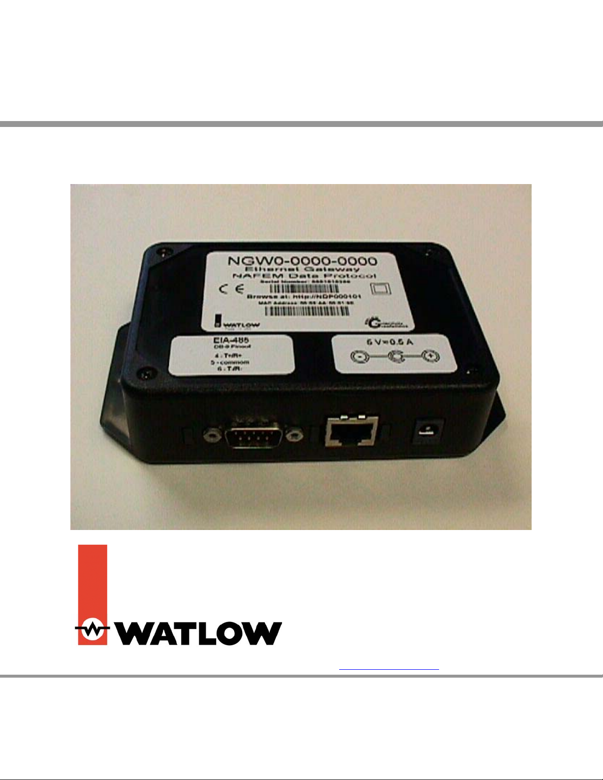
NAFEM Gateway
User’s Manual
For Watlow part numbers NGW0-0000-0000, NGW0-0000-2400, NGWC-0000-0000, NGWC-0000-2400
1241 Bundy Boulevard, P.O. Box 5580, Winona, Minnesota USA 55987-5580
Phone: +1 (507) 454-5300, Fax: +1 (507) 452-4507, Internet: http://www.watlow.com
0600-0040-0002 Rev C $10.00
September 2004
Page 2

NAFEM Gateway
Table of Contents Page
Product Overview 4
Network Services 4
Ethernet Gateway Architecture 5
Ethernet Wiring 5
Authentication and registration 6
Program Upgrades for Connected Devices 6
Alarm Notification 6
Supervisory Control and Data Acquisition 6
Poll Engine 6
Device Protocol 6
Installation & Wiring 7
Sample Decals 8
Configuration Overview 9
Getting Started 9
Password 10
View 11
Monitor Alarm 11
Monitor Configuration 12
Monitor Data 13
Monitor Notification 14
Configuration 15
Administration Community 15
Administration Network 16
Administration Notification 17
Asset Management Component Part ID 18
Asset Management Equipment ID 19
Bulk Transfer File Items 20
Bulk Transfer File Transfer 21
Bulk File Transfer Notification 22
Clock/Calendar Clock 23
Inventory Configuration 24
Inventory Data 25
Inventory Notification 26
Inventory Storage 27
Maintenance Notification 28
Maintenance Process Item 29
Maintenance Scheduled Item 30
Maintenance Unscheduled Item 31
Notify Host 32
Notify Event Log 33
Security User 34
Utility Alarm 35
Utility Management Configuration 36
Utility Management Data 37
Utility Notification 38
2
Page 3

Email Configuration 39
Gateway Serial Channel Entry 40
Gateway Serial Device Entry 41
Gateway Serial Point Entry 42
System Info 43
Diagnostics Defaults 43
Diagnostics Timing Analysis 44
Diagnostics Timing Configuration 45
Diagnostics Pool Memory 46
Diagnostics TCP/IP Stack 47
Diagnostics Event Log 48
Specifications 49
Operation 49
Real-time Clock 49
Serial Communications 49
Connectors 49
Power 49
Environmental Conditions 49
NAFEM Data Protocol Declaration of Conformity 50
How to Reach Us 51
Technical Assistance 51
Warranty 51
Returns 51
Your Feedback 51
3
Page 4

Introduction
This manual is intended for the user who is already familiar with the NAFEM protocol, Ethernet and
Modbus RTU. For more information see:
NAFEM Data Protocol User Manual located at:
http://www.nafem.org/resources/tech/DataProtocol.cfm
MODBUS RTU Standard located at:
http://www.modicon.com/techpubs/toc7.html.
RFCs located at: http://www.ietf.org/
Product Overview
The NAFEM Gateway has three physical connectivity points to the physical world; the device’s EIA-485
serial communication port, the RJ45 Ethernet network communication port (10BaseT) and the power
supply jack.
The NAFEM Gateway is a protocol converter that connects Modbus devices to the NAFEM protocol using
an Ethernet connection. The requirements are set forth by the selected protocols of register based
Modbus RTU for control devices and NAFEM Data Protocol [NDP] using digital signal connectivity.
This Gateway device performs these tasks with the use of six firmware components; Poll Engine, Alarm
Module, SNMP v1 Agent, Web Server, TFTP Client, and a Device Protocol Driver. In addition, a database
resides within the Gateway that contains the NAFEM Objects. This is where the information is exchanged
between the NAFEM and Modbus elements.
The function of the Gateway is to receive request for reads and writes of NAFEM Objects. These objects
are the registers within the devices. This request comes to the Gateway in the format of the NAFEM
protocol. The Gateway converts the request into the appropriate Modbus RTU packet and forwards the
information to the device. Up to 8 devices may be connected to the serial port. The Gateway can access
up to 64 registers divided between these devices. The information returned to the Gateway from the
device is converted into the NAFEM protocol and sent to the SNMP Manager or to the Web browser. The
Trivial File Transfer Protocol (TFTP) is used when program updates are sent to the Gateway or to a
device capable of flash re-programming.
Network Services
The NAFEM Gateway supports DHCP client, AutoIP, and static IP for address assignment. Normally you
will not need to make any changes. The user is able to configure preferences as to which services are
used if available. Intelligence is employed within the Gateway to revert to backup IP assignment methods
if the primary method is unavailable.
4
Page 5
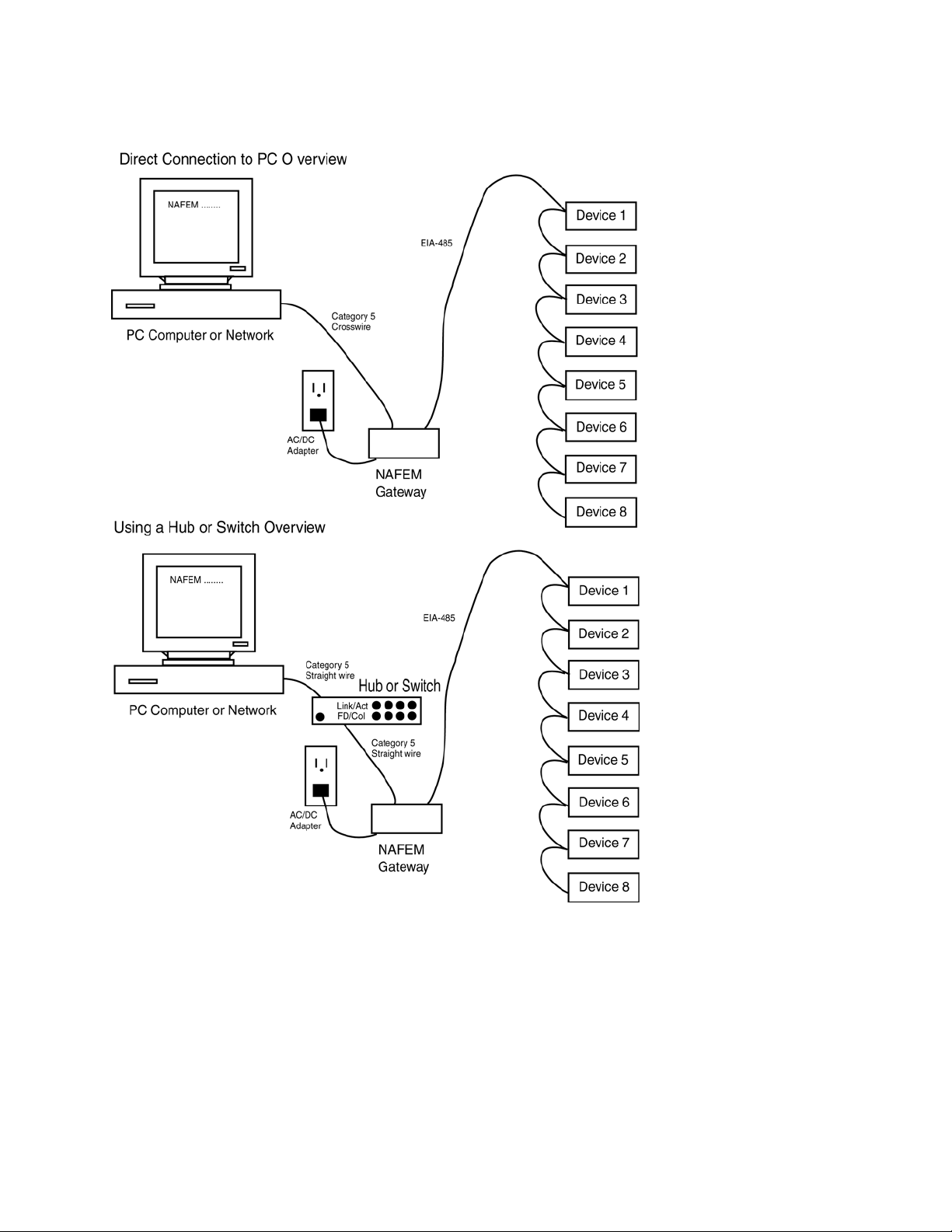
Ethernet Gateway Architecture
Ethernet Wiring
Connect the RJ-45 Ethernet jack to a Hub or Switch with standard CAT5 cable. The Gateway is a
10BaseT device, so a switch is the best solution for a multi-speed network. The device can be connected
directly to a computer's Ethernet jack with a crossover cable.
5
Page 6

Authentication and registration
Authentication and registration of the Gateway to the Ethernet is accomplished via a DHCP Client to a
system DHCP service if available. This may take up to 1 minute. The result of the DHCP method will
define the device's Internet Protocol address, SubNet mask and Default gateway. The Microsoft AutoIP
scheme is employed to address possible networking environments where DHCP services are not
available.
The Ethernet interface is designed to work without user intervention on most networks. Just connect to an
Ethernet network and browse the device. In order for the Gateway to communicate over an Ethernet
network, an address must be established and registered.
Program Upgrades for Connected Devices
Internal TFTP client protocol services will provide program upgrades over the network communications
port to a system TFTP server. This provides support for:
• Flash update of Gateway code
• Flash update of Modbus RTU code for products that support field firmware update
• File Transfer of multiple register RTU
Alarm Notification
This functioning and behavior is provided by the internal Firmware Alarm module and utilizes the Trap
function of the SNMPv1 Agent. Alarms are defined within the NAFEM PROTOCOL USER MANUAL along
with the behavior for acknowledgement and retries. All alarms specified and enabled by the user follow
this scheme. The Alarm notification supports:
- Clear Reset Alarm Action
- Bypass Disable Alarm Action
Supervisory Control and Data Acquisition
The Poll Engine reads parameters from the connected equipment and records the readings into the Data
Value of the assigned NAFEM Object Group for retrieval and review by the user via the SNMP Agent
services. Upon the modification of parameters via the SNMP v1 Agent by the user, the Poll Engine will
write parameters to the connected device.
Poll Engine
When the Poll Engine attempts to read from a remote device and an error occurs, the Poll Engine will
immediately retry to read from the remote device. If all retries have failed, then the Poll Engine shall
increment the protocol read message failure count by one and attempt the next poll attribute. If all active
attributes for a single device fail, then the poll engine shall disengage the device from the poll cycle.
When the Poll Engine attempts to write to a remote device and an error occurs, the Poll Engine will
immediately retry writing to the remote device. If all retries have failed, then the Poll Engine shall
increment the protocol write message failure count by one and reset the programmable attribute for the
write operation to the previous write value.
Device Protocol
Register based MODBUS RTU device protocol is used for communication between remote devices and
the Gateway with the Gateway acting as the communication MASTER. The following functions are
supported:
• Register Read
• Register Write
• Block Read
• Block Write
• Diagnostics
• Loop Back
6
Page 7
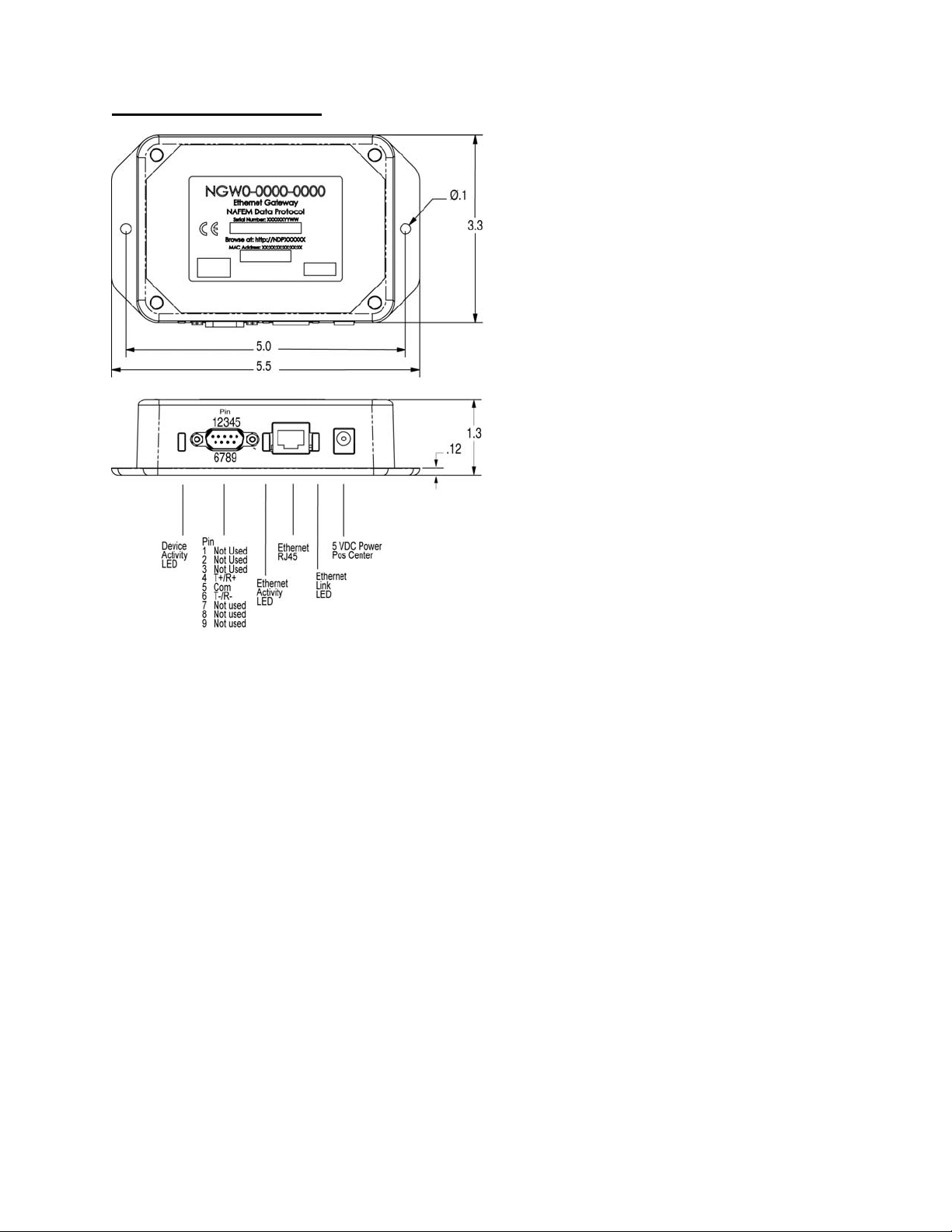
Installation & Wiring
Dimensions are in inches
Connect the T+/R+ to the devices’ T+/R+ terminals, the T-/R- to the devices’ T-/R- terminals and the Com
to the devices’ Com terminal in a daisy chain fashion.
Plug in an RJ45 Category 5 straight wired cable to an Ethernet switch / hub.
If you are connecting directly to a PC, you will need to use an RJ45 Category 5 cross-wired cable.
For Models NGWC-0000-0000 and NGW0-0000-0000, connect the 5-volt power supply plug to the power
supply jack. The inner terminal of the coaxial plug is positive.
For Models NGWC-0000-2400 and NGW0-0000-2400, connect the 24-volt power supply plug to the
power supply jack. The inner terminal of the coaxial plug is positive.
Note: Use proper ESD handling procedures when making connections to unit. A UL Class 2 and CE
approved power supply is required for compliance.
7
Page 8
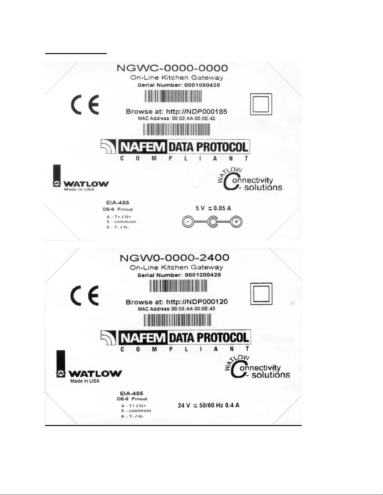
Sample Decals
8
Page 9

Configuration Overview
Two services are available within the Gateway or configuration. Either an HTTP browser or an MIB
browser may be used for configuration. An MIB browser and compiler is available from MG-SOFT Corp.
@ web site http://www.mg-soft.com.
Using a Network Browser Client with the on board Web Server provides the ability to configure the
NAFEM Gateway. Various HTML formatted pages are embedded within the device to provide a Graphical
User Interface (GUI) for configuration and review of the Gateway device.
A maximum of 8 devices may be connected to the EIA-485 port of the NAFEM Gateway. You will need to
configure the baud rate and Modbus addresses of the devices from the face of the devices. The choices
for baud rate are either 9600 or 19200. All devices must be set to the same baud rate. The addresses can
be set from 1 to 247. Each device must have a unique address.
Getting Started
Perform these steps;
1. Connect the NAFEM Gateway to your computer’s Ethernet port using a cross wired RJ45 cable or
connect the Gateway to a hub or network using a straight wired RJ45 Category 5 cable. The Gateway
is limited to a 10BaseT connection and will not work on an Ethernet port set for 100BaseT only. Use
of a 10/100 hub will overcome this issue if your PC has only a 100BaseT port.
2. Wire the temperature devices to the Gateway’s EIA-485 port.
3. Attach the appropriate power supply (5-volt or 24-volt DC) to the Gateway. The center pin is positive.
4. Configure each device to the same baud rate (9600 or 19200) from the front panel of the device. Set
each device’s Modbus address to a unique number. As an example, set the first device to address 1,
the second to address 2 and so on.
5. Power up the Gateway, devices and PC.
6. Start your Internet browser. Enter the TCP/IP address of the Gateway into the browser’s address
field. Two different addresses may be used to access the Gateway. Either NDPxxxxxx, where xxxxxx
is the first six digits of the serial number, or WATxxxxxx, where xxxxxx is the last six digits of the
Gateway’s MAC address. The MAC address is printed on a decal in the form xx:xx:xx:xx:xx:xx.
7. Select the Configuration, Gateway setup Page.
8. Configure the Serial Channel Entry, Serial Device Entry, and Serial Point Entry indexes.
The Gateway supports DNS client and Netbios name resolution. Configuration information may be
entered at the Configuration, Administration, Administration Network page.
9
Page 10
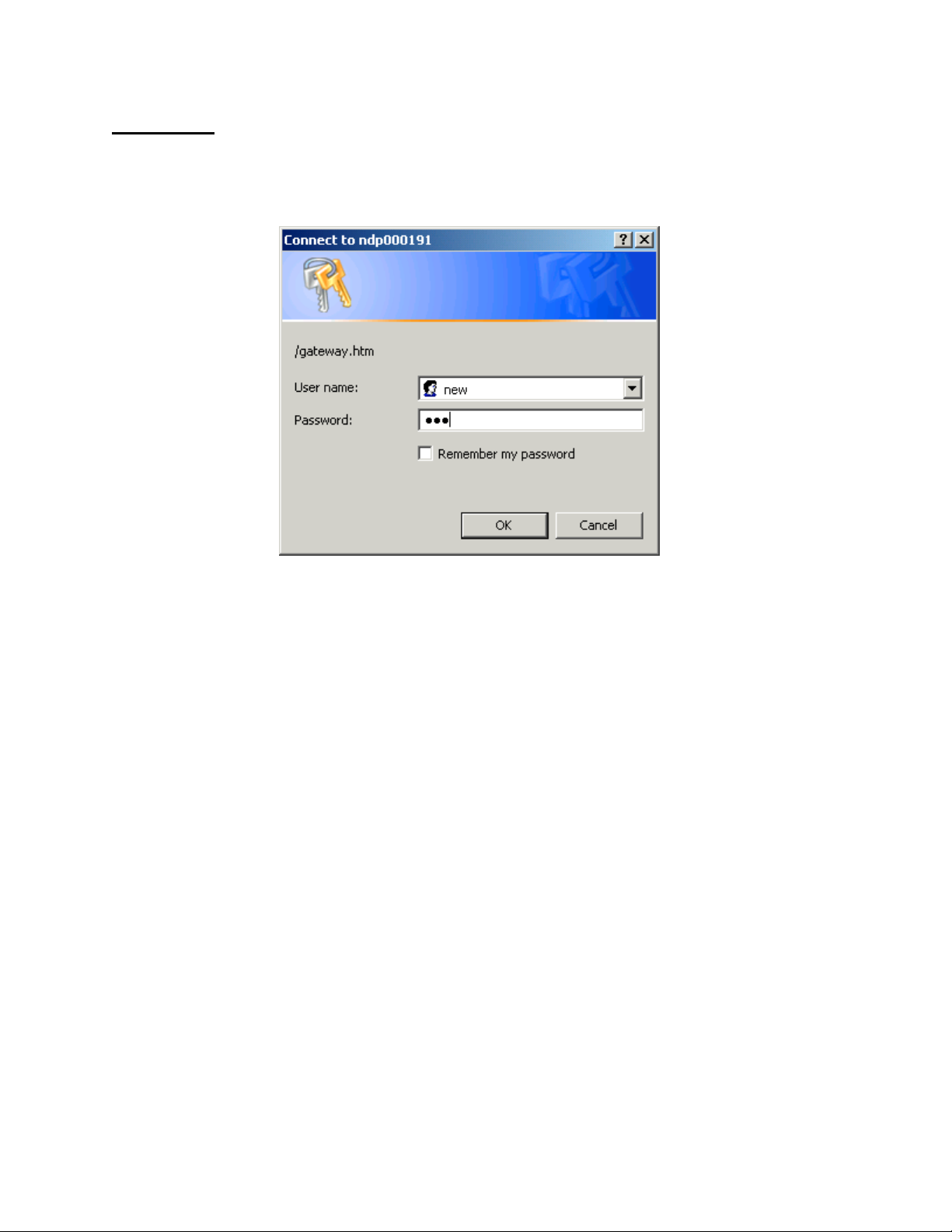
Password
Enter Network Password each time.
The default is:
User Name = new
Password = new
You may change these on the Security User screen.
10
Page 11
View
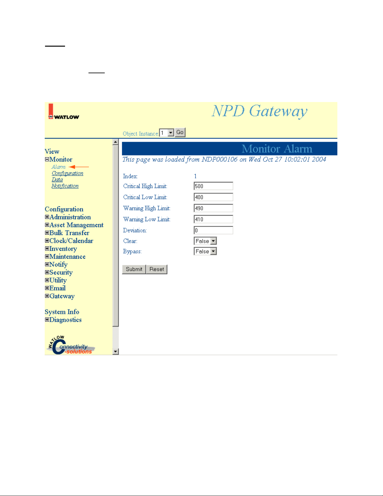
Monitor Alarm
Select Monitor, Alarm to access Monitor Alarm information.
Note: Click Submit to save changes. Reset will return these settings to the previous values if you have
not pressed the Submit button.
11
Page 12

Monitor Configuration
Select Monitor, Configuration to access Monitor Configuration information.
Note: Click Submit to save changes. Reset will return these settings to the previous values if you have
not pressed the Submit button.
12
Page 13
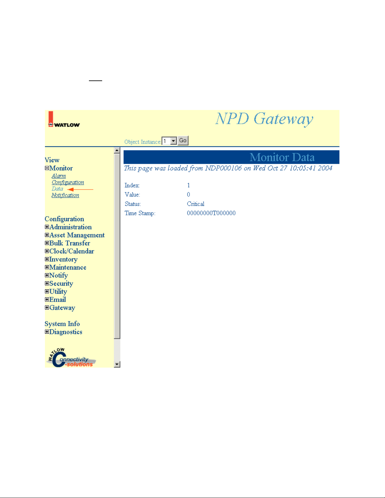
Monitor Data
Select Monitor, Data to access Monitor Data information.
Note: Click Submit to save changes. Reset will return these settings to the previous values if you have
not pressed the Submit button.
13
Page 14

Monitor Notification
Select Monitor, Notification to access Monitor Notification information.
Note: Click Submit to save changes. Reset will return these settings to the previous values if you have
not pressed the Submit button.
14
Page 15
Configuration
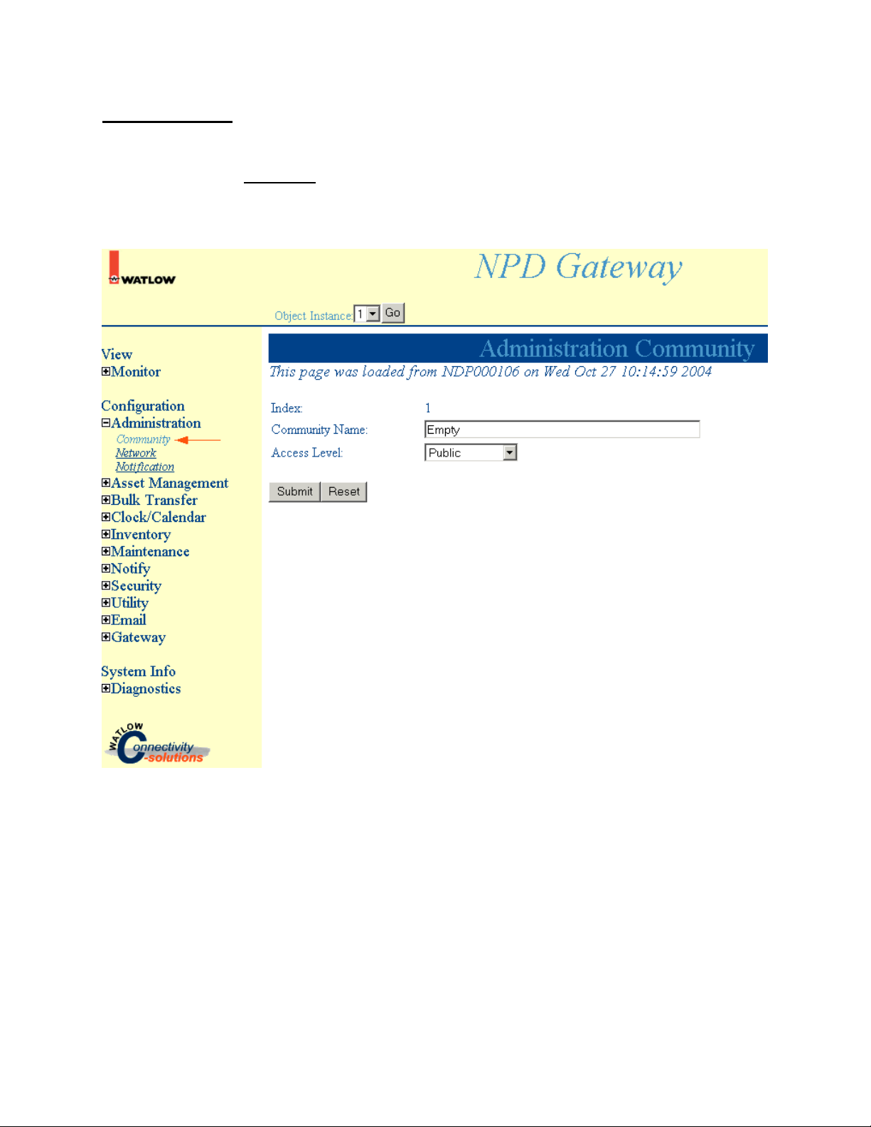
Administration Community
Select Administration, Community to access Administration Community information.
Note: Click Submit to save changes. Reset will return these settings to the previous values if you have
not pressed the Submit button.
15
Page 16

Administration Network
Select Administration, Network to access Administration Network information.
Note: Click Submit to save changes. Reset will return these settings to the previous values if you have
not pressed the Submit button.
16
Page 17

Administration Notification
Select Administration, Notification to access Notification Network information.
Note: Click Submit to save changes. Reset will return these settings to the previous values if you have
not pressed the Submit button.
17
Page 18

Asset Management Component Part ID
Select Asset Management, Component Part ID to access Asset Management Component Part ID
information.
Note: Click Submit to save changes. Reset will return these settings to the previous values if you have
not pressed the Submit button.
18
Page 19

Asset Management Equipment ID
Select Asset Management, Equipment ID to access Asset Management Equipment ID information.
Note: Click Submit to save changes. Reset will return these settings to the previous values if you have
not pressed the Submit button.
19
Page 20

Bulk Transfer File Items
Select Bulk Transfer, File Items to access Bulk Transfer, File Items information.
Note: Click Submit to save changes. Reset will return these settings to the previous values if you have
not pressed the Submit button.
20
Page 21

Bulk Transfer File Transfer
Select Bulk Transfer, File Transfer to access Bulk Transfer, File Transfer information.
Note: Click Submit to save changes. Reset will return these settings to the previous values if you have
not pressed the Submit button.
21
Page 22

Bulk File Transfer Notification
Note: Click Submit to save changes. Reset will return these settings to the previous values if you have
not pressed the Submit button.
22
Page 23

Clock/Calendar Clock
Note: Click Submit to save changes. Reset will return these settings to the previous values if you have
not pressed the Submit button.
23
Page 24

Inventory Configuration
Note: Click Submit to save changes. Reset will return these settings to the previous values if you have
not pressed the Submit button.
24
Page 25

Inventory Data
Note: Click Submit to save changes. Reset will return these settings to the previous values if you have
not pressed the Submit button.
25
Page 26

Inventory Notification
Note: Click Submit to save changes. Reset will return these settings to the previous values if you have
not pressed the Submit button.
26
Page 27

Inventory Storage
Note: Click Submit to save changes. Reset will return these settings to the previous values if you have
not pressed the Submit button.
27
Page 28

Maintenance Notification
Note: Click Submit to save changes. Reset will return these settings to the previous values if you have
not pressed the Submit button.
28
Page 29

Maintenance Process Item
Note: Click Submit to save changes. Reset will return these settings to the previous values if you have
not pressed the Submit button.
29
Page 30

Maintenance Scheduled Item
Note: Click Submit to save changes. Reset will return these settings to the previous values if you have
not pressed the Submit button.
30
Page 31

Maintenance Unscheduled Item
Note: Click Submit to save changes. Reset will return these settings to the previous values if you have
not pressed the Submit button.
31
Page 32

Notify Host
Note: Click Submit to save changes. Reset will return these settings to the previous values if you have
not pressed the Submit button.
32
Page 33

Notify Event Log
Note: Click Submit to save changes. Reset will return these settings to the previous values if you have
not pressed the Submit button.
33
Page 34

Security User
Note: Click Submit to save changes. Reset will return these settings to the previous values if you have
not pressed the Submit button.
34
Page 35

Utility Alarm
Note: Click Submit to save changes. Reset will return these settings to the previous values if you have
not pressed the Submit button.
35
Page 36

Utility Management Configuration
Note: Click Submit to save changes. Reset will return these settings to the previous values if you have
not pressed the Submit button.
36
Page 37

Utility Management Data
Note: Click Submit to save changes. Reset will return these settings to the previous values if you have
not pressed the Submit button.
37
Page 38

Utility Notification
Note: Click Submit to save changes. Reset will return these settings to the previous values if you have
not pressed the Submit button.
38
Page 39

Email Configuration
Note: Click Submit to save changes. Reset will return these settings to the previous values if you have
not pressed the Submit button.
39
Page 40

Gateway Serial Channel Entry
• Select Configuration, Gateway, Serial Channel, and Object Instance 1 to access this page. Configure
each serial channel entry. The baud rate, parity data bits, stop bits and protocol must match the
devices on the bus.
Note: Submit changes to save changes. Reset will return these settings to the previous values if you
have not pressed the Submit button.
40
Page 41

Gateway Serial Device Entry
• Select Configuration, Gateway, Serial Device Entry, and Object Instance 1 to access this page.
Configure a serial device entry for each device. A maximum of 8 devices can be configured.
• Enter a Name for reference. Set the Assignment Port to 1.
• Engaged must be set to Engage to have the device active.
• Enter the Address of the Modbus device. The range is 1 to 247.
• Set Port Delay, Health Check Rate and ID Check Rate to 0.
• Write and Read Count indicates the number of attempted write and read instructions to this device.
• The Write Error and Read Error Count are the number of failed attempts at writing and reading to this
device. The CRC Error Count is the number of packets returned with corrupted data within the
packet.
Note: Click Submit to save changes. Reset will return these settings to the previous values if you have
not pressed the Submit button.
41
Page 42

Gateway Serial Point Entry
• Select Configuration, Gateway, Serial Point Entry, and Select Object Instance 1 to access this page.
Configure each serial point entry. A serial point entry represents a data point or parameter of the
device.
• Enter a Name to identify the data point. In this example it has been named Fryer Temp.
• Class is the location to copy the data to from the data point.
• Device is the index of the device where the data point resides.
• Scan Rate is the frequency to acquire this data point in milliseconds. This value is added to the
maximum scan rate. A value of 5000 would add five seconds of time to the scan.
• Receive Type should be set to Signed 16 bit for Modbus register from Watlow devices.
• User Type determines the formatting of the data point for your application.
• The Register is the data point with in the device, entered as an absolute register number. Add 40001
to relative register numbers to obtain the absolute register number. See the appropriate device user’s
manual for a list of Modbus registers.
• Register Size is the length in bytes that are returned from the register.
• Gain Multiplier and Gain Divider are used to scale the returned data point value.
• Offset is used to shift the returned data point value in a positive or negative direction.
Note: Click Submit to save changes. Reset will return these settings to the previous values if you have
not pressed the Submit button.
8117.2.1.2.1.1.2.1
42
Page 43

System Info
Diagnostics Defaults
Note: Click Submit to save changes. Reset will return these settings to the previous values if you have
not pressed the Submit button.
43
Page 44

Diagnostics Timing Analysis
Note: Click Submit to save changes. Reset will return these settings to the previous values if you have
not pressed the Submit button.
44
Page 45

Diagnostics Timing Configuration
Note: Click Submit to save changes. Reset will return these settings to the previous values if you have
not pressed the Submit button.
45
Page 46

Diagnostics Pool Memory
Note: Click Submit to save changes. Reset will return these settings to the previous values if you have
not pressed the Submit button.
46
Page 47

Diagnostics TCP/IP Stack
Note: Click Submit to save changes. Reset will return these settings to the previous values if you have
not pressed the Submit button.
47
Page 48

Diagnostics Event Log
Note: Click Submit to save changes. Reset will return these settings to the previous values if you have
not pressed the Submit button.
48
Page 49

Specifications
Operation
Notification Handling per NAFEM PROTOCOL MANUAL for Alarm and Notification handling.
The Alarm Module performs the checking of parameter status and trigger notification events within 500
milliseconds.
Gateway accommodates a reading of all 64 remote device attributes from a single device in onesecond and all connected devices' attributes in four seconds.
SNMPv1Agent performs the interaction between the Gateway and the remote networked User's
Application running an SNMP manager. The SNMP v1 Agent will respond to the remote manager (User
application initiated) requests at a rate of 40 Hz - Reference RFC 1157.
TFTP Client - Reference RFC 1350.
Web Server performs the interaction between the Gateway and the remote networked User's
Browser. The Web Server will serve web pages to the remote browser (User initiated) at a rate of one
page every five seconds.
Poll Engine
The Poll Engine initiates communications between the Gateway and the remote devices. Individual SCAN
RATES are user programmable in one-second intervals. The Poll Engine performs these polls in an
asynchronous manner thereby eliminating the remote devices response time from time considerations of
internal events. The poll rate of the Poll Engine is 10 Hz assuming a 20 Hz remote device response time,
19200-baud rate, and no retry requirement.
Real-time Clock
The on board Real Time Clock circuit provides the Gateway with time reference and is read for
Gateway time clock updates on a one-minute interval. Accuracy is ± 4 minutes per year and provides
timing accuracy of ± 0.5% over a range of 0 to 999 seconds. Battery Backup provides a minimum of 6
years service.
Serial Communications
Complies with EIA-485 standards - supports 19200 and 9600-baud rates.
Connectors
RJ45 for Ethernet connection interface per IEEE 802.3
Coaxial power connector with positive center post
DB9 connector for Serial connection
Power
Input Voltage Ratings
5VDC for Wall Transformer interface with coaxial plug
UL⎛ approved, Class II power supply required
Input Power Ratings 10 Watts Maximum
Real-time Clock backed by 3v-lithium battery – RAYOVAC BR1225
Environmental Conditions
Operating temperature range: 0 to 60°C
Storage temperature range: -40 to 70°C
Operating and storage humidity: 0 to 90% non-condensing
49
Page 50

Declaration of Conformity
Gateway Products
Watlow Winona, Inc.
1241 Bundy Blvd.
Winona, MN 55987 USA
Declares that the following product:
Model Numbers: EM(XX)-GATE-(XXXX), *NGW(X)-(XXXX)-(XXXX) X = any number or letter
Classification: Communications interface card, Installation Category I, Pollution degree II
Rated Voltage:
Rated Frequency: 50/60 Hz or dc
Rated Power: 10VA maximum
*NGW with 5V power option requires use of a Ferrico NF130 Clamp on ferrite on all lines to pass Class B
emissions. Depending on end use setup, this bead may or may not be necessary.
Meets the essential requirements of the following European Union Directives by using the relevant
standards show below to indicate compliance.
24V (ac or dc) or 5V (dc)
89/336/EEC Electromagnetic Compatibility Directive
EN 61326:1997 +A1:1998 Electrical equipment for measurement, control and laboratory
use – EMC requirements (Industrial Immunity, Class B
Emissions).
EN 61000-4-2:1996 +A1, 1998 Electrostatic Discharge Immunity
EN 61000-4-3:1997 Radiated Field Immunity
EN 61000-4-4:1995 Electrical Fast-Transient / Burst Immunity
EN 61000-4-5:1995 +A1, 1996 Surge Immunity
EN 61000-4-6:1996 Conducted Immunity
EN 61000-4-11:1994 Voltage Dips, Short Interruptions and Voltage Variations Immunity
EN 61000-3-2:1995 +A1-3:1999 Harmonic Current Emissions
EN 61000-3-3:1995 +A1:1998 Voltage Fluctuations and Flicker
Use of an appropriately approved class 2 power source is required for compliance.
2001/95/EC General Product Safety Directive
EN 61010-1:2001 Safety Requirements of electrical equipment for measurement,
control and laboratory use. Part 1: General requirements
Raymond D. Feller III Winona, Minnesota, USA
Name of Authorized Representative Place of Issue
General Manager July, 2003
Title of Authorized Representative Date of Issue
Signature of Authorized Representative
Page 51

How to Reach Us
Technical Assistance
If you encounter a problem with your NAFEM Gateway, review all of your wiring and configuration
information to verify that your selections are consistent with your application. If the problem persists after
checking the above, you can get technical assistance from your local Watlow representative, or by dialing
(507) 454-5300. An applications engineer will discuss your application with you.
Warranty
This product is warranted free from defects in material and workmanship for 24 months after delivery to
the first purchaser for use, providing that the units have not been misapplied. Since Watlow has no
control over their use, and sometimes misuse, we cannot guarantee against failure. Watlow’s obligations
hereunder, at Watlow’s option, are limited to replacement, repair or refund of purchase price, and parts
that upon examination prove to be defective within the warranty period specified. This warranty does not
apply to damage resulting from transportation, alteration, misuse or abuse.
Returns
• Call or fax Customer Service for a Return Material Authorization (RMA) number before returning any
product.
• Put the RMA number on the shipping label, and provide a written description of the problem.
• A restocking charge of 20% of the net price is charged for all standard units returned to stock.
Your Feedback
Your comments or suggestions on this manual are welcome, please send them to: Technical Writer,
Watlow Winona, 1241 Bundy Blvd., P.O. Box 5580, Winona, MN 55987-5580, Phone: (507) 454-5300,
Fax: (507) 452-4507. Watlow Winona, Inc., ©, copyrights the NAFEM Gateway User’s Manual February
2002, with all rights reserved. (2212)
51
 Loading...