

Page 1

MLS
User’s Guide
Watlow Controls
1241 Bundy Blvd.
Winona, MN 55987
Customer Service
Phone: (800) 414-4299
Fax: (800) 445-8992
Technical Support
Phone: (507) 494-5656
Fax: (507) 452-4507
Email: wintechsupport@watlow.com
Part No. 11570-00. Revision 3.7
November 1995
Page 2

Copyright © 1995
Watlow-Anafaze
Information in this manual is subject to change without notice. No part of this publication may be
reproduced, stored in a retrieval system, or transmitted in any form without written permission from
W atlo w-Anaf aze.
Warranty
Watlow-Anafaze, Incorporated warrants that the products furnished under this Agreement will be
free from defects in material and workmanship for a period of one year from the date of shipment.
The customer shall provide notice of any defect to Watlow-Anafaze, Incorporated within one week
after the Customer's discovery of such defect. The sole obligation and liability of Watlow-Anafaze,
Incorporated under this warranty shall be to repair or replace, at its option and without cost to the
Customer, the defective product or part.
Upon request by Watlow-Anafaze, Incorporated, the product or part claimed to be defective shall
immediately be returned at the Customer's expense to Watlow-Anafaze, Incorporated. Replaced or
repaired products or parts will be shipped to the Customer at the expense of Watlow-Anafaze,
Incorporated.
There shall be no warranty or liability for any products or parts that have been subject to misuse,
accident, negligence, failure of electric power or modification by the Customer without the written
approval of Watlow-Anafaze, Incorporated. Final determination of warranty eligibility shall be
made by Watlow-Anafaze, Incorporated. If a warranty claim is considered invalid for any reason,
the Customer will be charged for services performed and expenses incurred by Watlow-Anafaze,
Incorporated in handling and shipping the returned unit.
If replacement parts are supplied or repairs made during the original warranty period, the warranty
period for the replacement or repaired part shall terminate with the termination of the warranty
period of the original product or part.
The foregoing warranty constitutes the sole liability of Watlow-Anafaze, Incorporated and the customer's sole remedy with respect to the products. It is in lieu of all other warranties, liabilities, and
remedies. Except as thus provided, Watlow-Anafaze, Inc. disclaims all warranties, express or
implied, including any warranty of merchantability or fitness for a particular purpose.
Please Note
: External safety devices must be used with this equipment.
Page 3

Addendum for MLS User’s Guide (3.6)
Addendum for MLS User’s
Guide (3.6)
The following are changes to revision 3.6 of the MLS User’s Guide. The
changes pertain to a new power supply that is being used with the MLS.
All changes are listed below by page number. Shaded portions refer to
the actual changed text.
These changes will be incorporated in the next manual revision.
System Power Requirements (from page 10)
MLS-PM supply input 10-28 Vdc at <1 amp
MLS-AIM supply input 4.75 to 5.25 Vdc at <0.5 amp, supplied by MLS-
PM
MLS-PS system power supply Input: 120/240 Vac at 0.75 amp
Output: 15 Vdc at 1.2 amp, 5 Vdc at 4 amp
Dimensions and Weight (from page 10)
MLS-PM 1.75 lbs., 1.89" x 3.78" x 6.75" (0.8 kg, 4.75 cm x 10 cm x 17
MLS-AIM-TB
& AIM cards
MLS-PS 1.2 lbs., 1.40" x 8.0" x 3.9" (0.6 kg, 3.56 cm x 20.32 cm x 9.91
RTB .5 lbs, 5.0’’ x 3.0’’ x 2.25’’ (.227 kg, 12.7 cm x 7.6 cm x 5.7 cm.)
1.50 lbs., 5.0" x 6.50" x 5.50" (0.7 kg, 12.5 cm x 16.25 cm x
cm.)
13.75 cm.)
cm.)
MLS User’s Guide (11570-00 rev. 3.6) I
Page 4

Addendum for MLS User’s Guide (3.6)
Mounting the MLS-PS (from page 23)
Follow these instructions to mount the MLS-PS.
If you use your own power supply for the MLS, please refer to the
power supply manufacturer's instructions for mounting information.
Choose a power supply that supplies a regulated 10 to 28 Vdc at 1 watt,
and isolated return line.
Mounting Environment
The MLS-PS measures 1.40" x 8" x 3.9". Leave enough clearance
around the power supply that you can remove it later.
Mounting Steps
The MLS-PS has a mounting bracket. The bracket has two screw holes
which will accept #6 or #10 screws. To mount the MLS-PS, attach the
power supply to your panel with the two screws and the power supply
mounting bracket.
II MLS User’s Guide (11570-00 r ev. 3.6)
Page 5
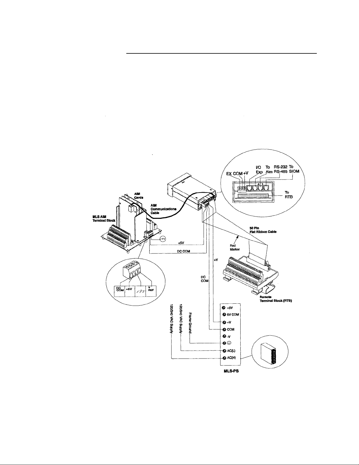
Wiring Your System (from page 24)
This section explains how to wire the components of your system.
Below is the system connections diagram reprinted here for your
convenience. (See the next page for wiring instructions.)
Addendum for MLS User’s Guide (3.6)
MLS User’s Guide (11570-00 rev. 3.6) III
Page 6

Addendum for MLS User’s Guide (3.6)
Wiring Recommendations (from page 25)
This section gives general wiring recommendations.
WARNING
Never wire bundles of low power Watlow-Anafaze
circuits next to bundles of high power AC wiring.
Instead, physically separate high power circuits
from the controller. If possible, install high voltage
AC power circuits in a separate panel.
Use stranded wire. (Use solid wire for fixed service; it makes inter-
•
mittent connections when you move it for maintenance.)
Use #18 or #20 AWG wire. Larger or smaller sizes may be difficult to
•
install, may break easily, or may cause intermittent connections.
•
Use shielded wire. (The electrical shield protects the MLS from
electrical noise.) Connect one end of the input wiring shield to the
MLS panel's 120/240 Vac panel ground, and connect one end of the
output wiring shield to the MLS panel's
120/240 Vac panel ground. (If your system requires a different
shield configuration, contact Watlow-Anafaze for more information.)
For more information about noise suppression, see Noise Suppression .
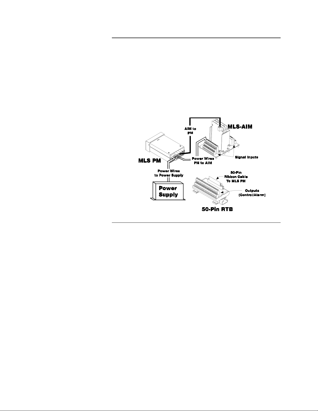
Connecting Power and RTB to MLS-PM (from page 27)
1. Remove the temporary covers you placed on the MLS' housing.
2. Connect the power supply terminal labeled "DC COM" to the terminal labeled "GND" on the Processor Module. This terminal is DC
common; it is not frame, chassis or earth ground.
3. Connect the power supply terminal labeled "+15V" to the terminal
labeled "+V" on the Processor Module.
4. Connect the 50-pin ribbon cable to the Processor Module. Plug it in
so that the red stripe is on the left side, under TB1.
5. Connect the ribbon cable to the RTB. Plug it in so that the red stripe is
closest to screw terminal 1.
IV MLS User’s Guide (11570-00 rev. 3.6)
Page 7

Contents
Overview .....................................................................1
System Diagram.................................................................. 2
Parts List .. .......................................................................... 2
Safety ....... .......................................................................... 3
Introduction................................................................5
Specifications......................................................................7
Analog Outputs.............................................................8
Digital Inputs ................................................................8
Digital Outputs.............................................................. 9
Miscellaneous Specifications............................................. 10
Serial Interface.............................................................. 10
System Power Requirements........................................ 10
Environmental Specifications.......................................10
Dimensions and Weight................................................10
Expanded Parts List............................................................11
MLS Processor Module Technical Description............ 11
MLS RTB Technical Description.................................13
MLS-AIM and AIM-TB Technical Description...........13
MLS Cabling Technical Description............................ 14
Installation..................................................................15
Read This Before Installation .............................................16
Recommended Tools ..........................................................17
Panel Hole Cutters........................................................ 17
Other Tools ...................................................................17
Additional Hardware..................................................... 17
Mounting the MLS-PM ...................................................... 18
Mounting Environment.................................................18
MLS-PM Mounting Steps............................................. 19
Mounting the MLS-AIM .................................................... 20
Mounting Environment.................................................20
Mounting Steps............................................................. 21
Mounting the RTB..............................................................22
Mounting the MLS-PS........................................................23
Mounting Environment.................................................23
Mounting Steps............................................................. 23
Wiring Your System........................................................... 24
Wiring Recommendations ............................................25
Cable Recommendations ..............................................26
Noise Suppression.........................................................26
Wiring and Testing Your System .......................................27
i
Page 8

Contents MLS User’s Guide
Connecting Power and RTB to MLS-PM.....................27
Connecting Power and Common to AIM-TB...............28
Testing Connections ..................................................... 28
Testing Your System .......................................................... 30
MLS-AIM Test .............................................................30
RTB Test.......................................................................30
PID Output Test............................................................ 30
Outputs..... ..........................................................................31
PID Control and Alarm Output Connections................ 33
RTB Connections.......................................................... 34
AIM Communications Failure...................................... 35
Inputs ....... ..........................................................................36
Input Wiring Recommendations................................... 37
Input Scaling.................................................................37
T/C Inputs .....................................................................39
RTD Inputs ................................................................... 40
Current Inputs ...............................................................41
Voltage Inputs...............................................................41
Unused Inputs ...............................................................41
Communications................................................................. 42
Changing Communications...........................................42
Connecting RS-232 Communications .......................... 42
Connecting RS-485 Communications .......................... 43
Recommended Wire Gauges ........................................ 45
Using the MLS............................................................47
Front Panel.......................................................................... 48
Front Panel Keys........................................................... 49
Displays ... ..........................................................................51
Viewing Several Loops: Bar Graph Display ................ 51
Viewing One Loop: Single Loop Display ....................52
Interpreting Alarm Display........................................... 53
Displaying, Loading, and Saving Jobs................................55
Operator Menus .................................................................. 56
Changing the Setpoint................................................... 56
Selecting Manual, Automatic, or Tune Control............ 56
Setup ...........................................................................59
How to enter the Setup menus? ....................................59
How to edit a menu?..................................................... 59
Setup Global Parameters Menu ..........................................61
Save to Job....................................................................62
Load from Job............................................................... 62
Job Select Inputs........................................................... 63
ii
Page 9

MLS User’s Guide Contents
Job Digital Input Polarity.............................................. 64
Output Override Digital Input....................................... 64
Output Override Input Polarity.....................................64
Startup Alarm Delay..................................................... 65
Keyboard Lock Status................................................... 65
Power-Up Output Status............................................... 65
Controller Address........................................................ 66
Communications Error Checking .................................66
Communications Baud Rate .........................................67
Allen Bradley Protocol .................................................67
AC Line Frequency....................................................... 67
Digital Output Polarity..................................................68
AIM Communications Failure Output.......................... 68
EPROM Information.....................................................68
Setup Loop Input .......................................................... 69
Input Type.....................................................................70
Pulse Sample Time .......................................................71
Loop Name ................................................................... 71
Input Units ....................................................................71
Input Reading Offset..................................................... 72
Linear Scaling Menus................................................... 72
Display Format ............................................................. 74
High Process Value....................................................... 74
High Reading................................................................ 75
Low Process Value .......................................................75
Low Reading.................................................................75
Input Filter ....................................................................76
Setup Loop Control Parameters.......................................... 77
Heat/Cool Control PB................................................... 78
Heat/Cool Control TI....................................................78
Heat/Cool Control TD .................................................. 78
Heat/Cool Output Filter................................................ 79
Heat/Cool Spread.......................................................... 79
Setup Loop Outputs............................................................ 80
Enable/Disable Heat and Cool Outputs ........................82
Heat or Cool Output Type ............................................ 82
Heat/Cool Cycle Time..................................................83
SDAC Menus...................................................................... 83
SDAC Mode ................................................................. 83
SDAC High Value........................................................ 84
SDAC Low Value......................................................... 84
Heat/Cool Output Action..............................................84
Heat/Cool Output Limit................................................ 85
Heat/Cool Output Limit Time.......................................85
iii
Page 10

Contents MLS User’s Guide
Heat/Cool Output Override........................................... 85
Heat/Cool Nonlinear Output Curve.............................. 86
Setup Loop Alarms............................................................. 87
Alarm Types ................................................................ 88
Alarm Delay..................................................................90
High Process Alarm Setpoint........................................ 91
High Process Alarm Type............................................. 91
High Process Alarm Output Number............................ 91
Deviation Band Value................................................... 92
High Deviation Alarm Type .........................................92
High Deviation Alarm Output Number ........................93
Low Deviation Alarm Type.......................................... 93
Low Deviation Alarm Output Number......................... 93
Low Process Alarm Setpoint ........................................94
Low Process Alarm Type ............................................. 94
Low Process Alarm Output Number ............................ 94
Alarm Deadband........................................................... 95
Loop Alarm Delay ........................................................95
Manual I/O Test..................................................................96
Digital Input Testing..................................................... 97
Keypad Test.................................................................. 97
Test Digital Output .......................................................97
Toggle Digital Output................................................... 98
Tuning and Control....................................................99
Introduction......................................................................... 99
Control Modes ....................................................................99
On/Off Control.............................................................. 99
Proportional Control..................................................... 100
Proportional and Integral Control.................................101
Proportional, Integral and Derivative Control.............. 101
Digital Output Control Forms....................................... 102
Setting Up and Tuning PID Loops ..................................... 104
Proportional Band (PB) Settings...................................104
Integral Term (TI) Settings........................................... 105
Derivative Term (TD) Settings..................................... 105
General PID Constants........................................................ 106
Proportional Band Only (P).......................................... 106
Proportional with Integral (PI)...................................... 106
PI with Derivative (PID)...............................................106
Troubleshooting..........................................................109
Manual Controller Reset............................................... 109
Returning your Unit to ANAFAZE..............................110
iv
Page 11

MLS User’s Guide Contents
Troubleshooting Stand-Alone Systems .............................. 110
MLS-PM Has No Power...............................................110
Keys Don't Respond......................................................111
Controller Message: AIM Comm Failure..................... 111
Checking Analog Inputs ...............................................111
Checking PID Control Outputs..................................... 112
Checking Digital I/O..................................................... 112
Checking Computer Supervised Systems...........................113
Computer Problems ......................................................113
Serial Interface Problems.............................................. 113
Communications Problems........................................... 114
Software Problems........................................................ 115
Changing the EPROM.................................................. 116
Linear Scaling Examples...........................................119
Example 1: Configuring a Pressure Sensor ........................119
Example 2: Configuring a Flow Sensor.............................. 120
Glossary ......................................................................121
v
Page 12

Contents MLS User’s Guide
vi
Page 13

Overview
Overview
This manual describe s h ow t o in st all , s et up, and operate a 16 or 32 MLS
controller. Included are seven chapters and a glossary of terms. Each
chapter covers a different aspect of your control system and may apply
to different users. The following describes the chapters and their
purpose.
•
Introduction: Gives a general description of the MLS and its
related specifications.
•
Installation: Describes how to install the MLS and its peripheral
devices.
•
Using the MLS: Provides an overview of operator displays used for
system monitoring.
•
Setup: Describes all the setup displays for the controller, and how to
access them.
•
Tuning and Control: Explains PID control and provides tips for
tuning your system.
•
Troubleshooting: Gives some basic guidelines for solving control
problems.
•
Linear Scaling Exa mples: Provides an example configuring a pres-
sure sensor, and one configuring a fl ow sensor.
MLS User’s Guide 1
Page 14
Overview
System Diagram
The illustration below shows how the parts of the MLS are connected.
When unpacking your system, use the diagram and parts list below to
ensure all parts have been shipped. Please don't hesitate to call Watlow-
Anafaze's Technical Service Department if you have problems with
your shipment, or if the MLS' components are missing or damaged.
Parts List
•
MLS Processor Module (PM)
•
Controller Mounting Kit
•
MLS AIM Module (16 or 32)
•
AIM Cable, 4 foot.
•
RS-232 or RS-485 Com Cable (optional)
•
RTB Terminal Block
•
50-Pin Ribbon Cable
•
Power Supply (optional)
2 MLS User’s Guide
Page 15

Safety
Overview
Watlow-Anafaze has made efforts to ensure the reliability and safety of
the MLS™ Controller and to recommend safe usage practices in
systems applications. Please note that, in any application, failures can
occur. These failures may result in full control outputs or other output s
which may cause damage to or unsafe conditions in the equipment or
process connected to the MLS Controller.
Good engineering practices, electrical codes, and insurance regulations
require that you use independent external safety devices to prevent
potentially dangerous or unsafe conditions. Assume that the Watlow-
Anafaze MLS Controller can fail with outputs full on, outputs full off,
or that other unexpected conditions can occur.
Install high or low temperature protection in systems where an
overtemperature or undertemperature fault condition co uld present a fire
hazard or other hazard. Failure to install temperature control protection
where a potential hazard exists could result in damage to equipment and
property, and injury to person nel.
The MLS includes a reset circuit that sets the control outputs off or to
the data stored in memory if the microprocessor resets--normally the
result of a power failure and power return. If a memory-based restart
will be unsafe for your process, program the MLS Controller to restart
with outputs off. For additional safety, program the computer or other
host device to automa tically reload the desired operating constants or
process values on return of operating power. However, these safety
features do not eliminate the need for external, independent safety
devices in potentially dangerous or unsafe conditions.
Watlow-Anafaze also offers ANASOFT
®
program for IBM-AT
event of a reset, ANASOFT will reload the MLS Controller with the
current values in computer memory. The user must ensure that this reset
will be safe for the process. Again, use of ANASOFT does not eliminate
the need for appropriate external, independent safety devices.
Contact Watlow-Anafaze immediately if you have any questions about
system safety or system operation.
or IBM-PC® compatible computers. In the
®
, an optional software
MLS User’s Guide 3
Page 16

Overview
4 MLS User’s Guide
Page 17

Introduction
The MLS is a modular control system with 32 fully indepe ndent loops
of PID control. It can function as a stand-alone controller; the MLS
processor module's 1/8 DIN front panel has a Liquid Crystal Display
(LCD) and touch keypad for local display and local p arameter entry.
You can also use it as the key element in a computer-supervised data
acquisition and control system; the MLS can be locally or remotely
controlled via an RS-232 or RS-485 serial communications interface.
The MLS features include:
Direct Connection of Mixed Thermocouple Sensors: V ersatile analog
inputs let you directly connect most thermocouples. Thermocouple
inputs feature reference junction compensation, linearization, PV offset
calibration to correct for sensor inaccuracies, T/C upscale break
detection, and your choice of Fahrenheit or Celsius display.
Introduction
Resistive Temperature Detector Sensors are Standard Inputs: The
standard three-wire 100 W platinum DIN curve sensor is a standard
input for the MLS, as well as the Nickel RT D.
Automatic Scaling of Linear Analog Inputs: The MLS automatically
scales linear inputs used with other industrial process sensors. To scale
inputs, simply enter any two measurement points. For example, to scale
a pH sensor enter the endpoints: the low PV is 2.0 pH, while the high
PV is 14.0 pH. All subsequent values will be in pH.
Independently Selectable PID Output Modes: Y ou can set each loop's
digital output to ON/OFF, Time Proportionin g, Serial DAC, or
Distributed Zero Crossing mode. You can set each loop control mode
for ON/OFF, P, PI, or PID control with reverse or direct action output.
Flexible Alarm Outputs: You can set independent high/low process
alarms and a high/low deviation band alarm for each loop. Each alarm
can activate an individual digital output or it can be grouped with other
alarms to activate a single digital output.
Alarm or Control Outputs: You can set high/low deviation and high/
low process setpoints to operate separate dig ital outputs as on/off
control functions instead of as alarms. (The control function will not
have alarm notification or global alarm output.)
Global Alarm Output: When any alarm is triggered, the Global Alarm
Output is also triggered, and it st ays on until you acknowledge it.
Watchdog Timer: The MLS watchdog timer (System Safe) output
provides a digital output which notifies you if the system fails.
MLS User’s Guide 5
Page 18

Introduction
Front Panel or Computer Operation: You can set up and run the MLS
Controller from the processor module's front panel or from a local or
remote computer. Watlow-Anafaze offers ANASOFT, our IBM-AT or
IBM-PC compatible software you can use to operate the MLS.
ANASOFT has these features:
•
Graphic Trend Plotting
•
Process Overviews
•
Printouts
•
Data Archiving in Lotus-Compatible Files
Multiple Job Storage: You can store up to 8 jobs in protected memory
and access them by entering a single job number. Each job is a set of
operating conditions, in cluding setpoi nts an d alarms- -so if a si ngle oven
produces multiple products, simply enter one job number to set up every
loop.
Dual Outputs Standard for 16 Loops: The 16-loop MLS Controller
includes dual control outputs for each loop, and a second set of control
constants for heating and cooling applications.
Flexible Outputs Standard for 32 Loops: The 32-loop MLS
Controller is factory set for a single heat output for each input. Outputs
for loops 17-32 can be assigned as second outputs for loops 1-16.
6 MLS User’s G uide
Page 19

Specifications
This section shows specifications for the MLS, including inputs,
outputs, serial interface information, system power requirements, and
environmental and physical specifications.
Analog Inputs
Number of control loops 16 dual output or 32 singl e output plus one pulse
loop.
Number of analog inputs 16 (with AIM-16) or 32 (with AIM-32).
Input switching Differential solid state MUX switching.
Input sampling rate 16 loops per second.
Analog over-voltage protection between
inputs
Maximum analog input voltage +10 V from + or - input to analog common.
Common mode voltage 500 Vac maximum analog common to MLS-PM
CMR (Common Mode Rejection) >85 dB at 60 Hz, 110 dB typical.
A/D converter Integrates voltage to frequency.
Integration time per loop 33.3 ms at 60 Hz line frequency.
Input range -10 to +60 mV, or 0 to 25 V with s caling resis-
Resolution 0.02%, greater than 12 bits (intern a l)
Accuracy
Calibration Automatic zero and full scale.
Temperature coefficient
Analog Ground to frame Ground Max.
potential
DC Common to frame Ground Max. potential
70 V peak to peak maximum.
or MLS-AIM power supply common.
tors.
0.1% at 25
Less than 100 ppm/
40 V
40 V
°
C
°
C, 0.01% per °C.
Introduction
Thermocouple Ranges
J
K
T
B
S
R
-350 to 1400
-450 to 2500
-450 to 750
150 to 3200
0 to 3200
0 to 3210
°
F (-212 to 760°C)
°
F (-268 to 1371°C)
°
F (-268 to 399°C)
°
F (+66 to 1760°C)
°
F (-18 to 1760°C)
°
F (-18 to 1766°C)
MLS User’s Guide 7
Page 20
Introduction
RTD Ranges
RTD1
RTD2
RTD3
T/C break detection Pulse type for upscale break detection and
Milliamp inputs 0-10 mA, 0-20 mA (4-20 mA), etc., with scal-
Infrared inputs power supply included, with scaling resistors
Source impedance Measurements are within specification with
Analog Outputs
The Watlow-Anafaze Digital to Analog Converter (DAC) is an optional
module for MLS and CLS control le rs . It l et s y ou co nver t a dis t ri bu ted zero
crossing output si gnal to an analog pr ocess contro l sig nal. You can purchase
Watlow-Anafaze also offers the Serial DAC for precision open-loop con-
trol. 0-5 Vdc / 4-20 mAdc jumper selectable. Contact Watlow-Anafaze for
-148.0 to 572
-184 to 1544
-94 to 572
°
F (-100.0 to 300.0°C)0.1
°
F (-120 to 840°C)1.0
°
F (-70 to 300°C)1.0
Miscellaneous Specifications
thermocouple alarm display.
ing resistors.
for IRSM.
up to 500 ohms source resistance.
4-20 mAdc, 0-5 Vdc, and 0-10 Vdc versions of the DAC.
more information about the DAC and Serial DAC.
°C
°C
°C
Digital Inputs
Input voltage protection Diodes to supply and common
Absolute maximum input
Maximum input current 1.2 mA from MLS with input at zero volts
Maximum switch resis-
tance to pull input low
Minimum switch off resis-
Number 8
+
10 mA
current
Voltage levels <1.3V=Low; >3.7V=High
1 Kohm
11 Kohm
tance
8 MLS User’s G uide
Page 21
Digital Outputs
Standard Digital Outputs
Number 34 continuous 10 mA sink referenced to +5 Vdc of MLS
for SSR operation; 20 mA momentary peak sink.
User selectable outputs 34 PID control, Alarm/control, or Events. T wo outputs are
not PID programmable.
Number of PID loops 16 or 32 programmable loops. 16-loop systems have dual
outputs. 32-loop systems have 32 sing le outputs, and you
can individually configure outputs 17-32 as a second out-
puts for loops 1-16.
PID control outp uts Time Proportioning, Distributed Zero Crossing, or On/
Off--all independently selectable for each loop.
Cycle Time 1-255 seconds.
Control Action Reverse (heat) or Direct (cool), independently selectable
for each loop.
Off State Leakage Current <.01 mA to DC common.
Introduction
System Digital Outputs
Number of system digital
outputs
Configuration 1 global alarm, 5 Vdc at 10 mA sink; 1 System Safe (CPU Watch-
dog Timer), 5 Vdc at 10 mA sink.
2
MLS User’s Guide 9
Page 22
Introduction
Miscellaneous Specifications
Serial Interface
Number of Controllers 1 with RS-232 communicati ons, 32 with RS -485 co mmuni cations ,
System Power Requirements
Type RS-232 3-wire or RS-485 4-wire.
Isolation RS-232: None
RS-485: To EIA RS-485 specification.
Baud Rate 2400 or 9600, user selectable.
Error Check BCC or CRC, user selectable.
16 with open frame units.
Protocol Form of ANSI X3.28-1976, (D1, F1) compatible with Allen-Brad-
ley PLC, full duplex.
MLS-PM supply input 10-28 Vdc at <1 amp
MLS-AIM supply input 4.75 to 5.25 Vdc at <0.5 amp, supplied by
MLS-PM
MLS-PS system power supply Input: 120 Vac at 0.5 amp
Output: 12 Vdc at 1 amp
Environmental Specifications
Storage Temperature
Operating Temperature
Humidity Conditions 10 to 95% non-condensing
Dimensions and Weight
MLS-PM 1.75 lbs., 1.89" x 3.78" x 6.75" (0.8 kg, 4.75 cm x 10 cm x 17
MLS-AIM-TB
& AIM cards
MLS-PS 1.50 lbs., 1.90" x 8.10" x 4.90" (0.7 kg, 4.75 cm x 20.25 cm x
RTB .5 lbs, 5.0’’ x 3.0’’ x 2.25’’ (.227 kg, 12.7 cm x 7.6 cm x 5.7 cm.)
1.50 lbs., 5.0" x 6.50" x 5.50" (0.7 kg, 12.5 cm x 16.25 cm x
-20 to 70
0 to 50
cm.)
13.75 cm.)
12.25 cm.)
º
C
º
C
10 MLS User’s Guide
Page 23

Expanded Parts List
The Expanded Parts List contains a technical description of each
component of your MLS Controller.
MLS Processor Module Technical Description
The MLS Processor Module (MLS-PM) is housed in an eighth-DIN
panel mount package. It contains the power supply circuits, the CPU,
RAM with a built-in lithium battery socket, EPROM, serial
communications, digital I/O, and the LCD screen and touch keypad.
Here's a side view of the MLS-PM:
Introduction
•
Screw terminals connect the power inputs and outpu t s.
•
Input power is 10-28 Vdc at 1 amp.
•
The +5 Vdc, 750 mAdc output po wer s upp ly po wer s th e MLS- A IM.
•
A 50-pin flat ribbon cable connects the digital inputs and outputs to
the 50-pin terminal block (TB-50).
•
The MLS uses 6-pin telephone-style connectors for internal and
external communications.
The firmware's operating intelligence resides in the plug-in EPROM, so
it's easy to update or change the MLS' firmware. The MLS stores its
operating parameters in battery-backed RAM, so if there's a power loss
the operating parameters are unchanged. The battery has a ten year shelf
life, and it is not used when the unit is on.
The CPU microprocessor performs all calculations for input signal
linearization, PID control, alarms, and communications.
The telephone connectors on the rear of the MLS-PM are used for:
•
Communications to the MLS-AIM.
•
RS-232 or RS-485 communications to an optional computer.
•
For OEM customers, communications to the optional MLS Smart I/
O Module (MLS-SIOM).
The System safe output is Low (On) when the CPU is running; it keeps
a solid state relay closed. If the CPU stops working, the output goes
High (Off) and the SSR opens.
MLS User’ s Guide 11
Page 24
Introduction
The eight digital inputs are referenced to the MLS controller common;
an open input pulls them High (Off). When you short the input to
controller common the input goes Low (On). Do not connect external
power sources to the MLS' digital inputs.
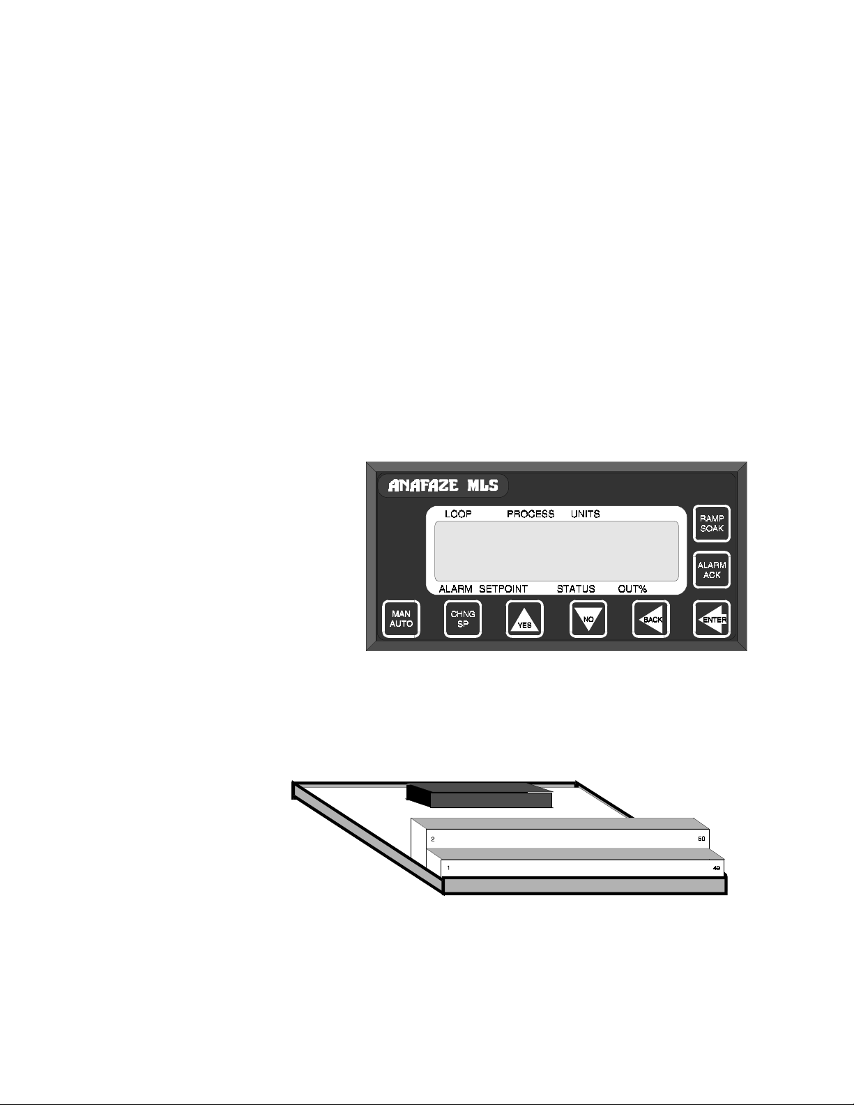
Front Panel Description
The MLS-PM's panel mounted LCD screen and touch keypad provide
an intelligent way to operate the MLS. The on-board display driver
operates the liquid crystal display. The LCD has 16 alphanumeric or
graphic characters per line; it is backlit for viewing under low light
conditions. The 8-key keypad and on-boar d keyboard scanner allo w you
to change the MLS' operating parameters, controller functions, and
displays.
The MLS' information-packed displays show process variables,
setpoints, and output levels for each loop. A bar graph display, single
loop display, scanning display and an alarm display offer a real-time
view of process conditions. Two access levels allow operator changes
and supervisor changes. The front panel looks like this:
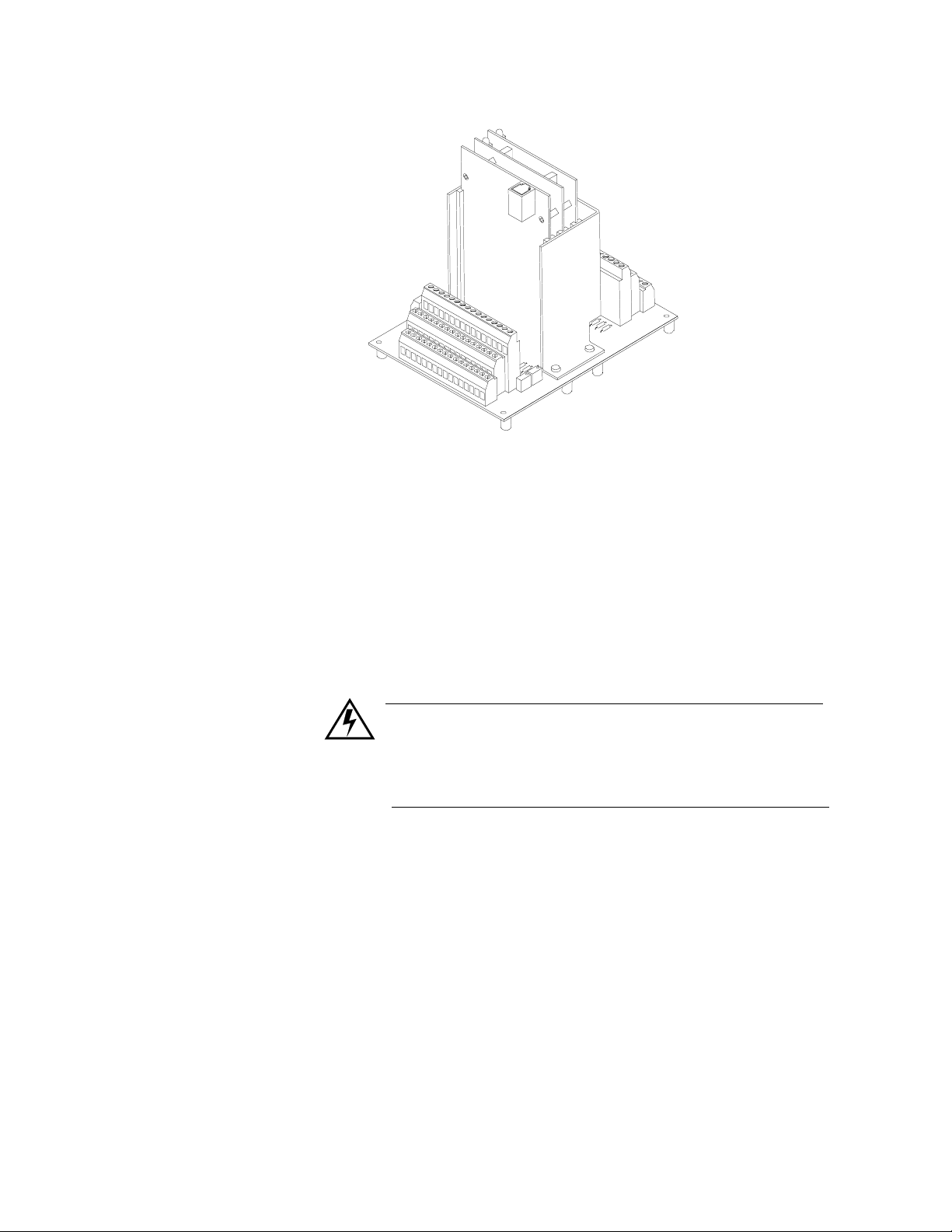
MLS RTB Technical Description
12 MLS User’s Guide
Here's a picture of the RTB:
Page 25

The RTB is a screw terminal interface for control wiring which allows
you to easily connect external "real world" wiring to the MLS. The RTB
connects a 50-pin flat ribbon cable to a screw terminal block which
accepts #18 or #20 AWG wires. The ribbon cable receptacle has a
locking latch which keeps the cable in place.
The RTB's 34 digital outputs are sink outputs referenced to the +5 Vdc
power supply of the MLS Controller. They are Low when the output is
On. The firmware allows you to globally change the alarm and control
outputs' default state (no alarms) f rom On to Of f for System Safe outpu t.
The outputs are rated at a continuous 10 mAdc if all outputs are On at
the same time. Initial power up current should not exceed 20 mAdc.
MLS-AIM and AIM-TB Technical Description
The MLS Analog Input Module (MLS-AIM), containing the AIM-TB
(AIM Terminal Board) and AIM’s plug-in cards, receive input signals
from sensors and pass them to the MLS-PM.
Introduction
The MLS-AIM-TB contains the power supply terminals, input signal
wiring screw terminals, input signal cond itioning circuits, and terminal
connections for the AIM's plug-in cards. It also contains a cold junction
temperature sensor and room for the input scaling resistors, if required.
(RTDs, inputs greater than 60 mVdc, and mAdc current inputs require
input scaling resistors.) The AIM-TB has three slots for the plug-in
AIM cards.
There are two versions of the MLS-AIM: the AIM-16 and AIM-32. The
AIM-16 has one multiplexer (MUX) card, and the AIM-32 has two
MUX cards. These cards multiplex the 16 inputs each card receives.
Each -10 to 60 mVdc input is converted to a voltage that is transm itted
to the Voltage/Frequency (V/F) card. (The MUX cards also
automatically calibrate the zero and span of the analog amplifier and
measure the cold junction compensation temperature for thermocouple
(T/C) inputs.) Both the AIM-16 and AIM-32 have a V/F card, which
converts the input signal they receive from a voltage to a frequency . The
converted signal is then transmitted via the AIM COMM cable to the
MLS-PM for processing.
MLS User’s Guide 13
Page 26
Introduction
MLS Cabling Technical Description
Here's a picture of the MLS-AIM-32 and terminal block:
Watlow-Anafaze provides all the cables required to install your MLS.
The 50 pin ribbon cable which connects the RTB to the MLS-PM is an
0.05 space conductor-zoned 50 pin cable. Pin #1 is at the red edge of the
cable.
The cables which connect the MLS-PM to the AIM-TB, the optional
Smart I/O Module (SIOM) and the computer are 6-conductor shielded
cable. (These cables are also known as RJ12 cable; they are available
from Newark Electronics and other suppliers.)
WARNING
These cables are not standard phone cables; standard cables are not shielded. Watlow-Anafaze pin
numbering convention is also reversed.
14 MLS User’s Guide
Page 27
Installation
Installation
These installation instructions are written for nontechnical users. If you
are an electrician or you are technically proficient, they may seem
simple to you. Please at least skim all of the instructions, to make sure
you don't miss anything vital. (If you have installed a Modular Loop
System before, you may wish to use the Quick Start foldout to install
this system.)
This section explains installation for the MLS Controller only. If you are
installing another Watl ow-Anafaze product (such as a Relay Interface
Board, IRSM, or an SDAC), see the manual shipped with it to learn how
to install it.
These symbols are used throughout this manual:
DANGER
This symbol warns you a bout a hazard to hu man
life.
WARNING
This symbol warns you of possible damage to
property or equipment.
NOTE
This symbol denotes information you must know
in order to proceed.
MLS User’s Guide 15
Page 28
Installation
Read This Before Installation
WARNING
During installation and wiring, place temporary
covers over the housing slots and the rear of the
MLS so dirt and pieces of wire don't fall through
the slots. When you are finished with installation,
remove the covers.
Install the MLS so the airflow to the slots in the
housing is not restricted after installation. Make
sure that other equipment does not block airflow
to the housing slots.
Use #18 or #20 AWG wires and trim wire insulation to 1/4" (5 mm). Wire should fit inside the
terminal with no bare wire exposed, to prevent
contact between wires and the grounded case. Tin
any stranded wire.
Support power, input and output cables to reduce
strain on the terminals and to prevent wire
removal.
DANGER
Shut off power to your process before you install
the MLS. High voltage may be present even when
power is turned off! Reduce the dan ger of electri c
shock after installa tion--mount the MLS in an
enclosure that prevents personal contact with electrical components.
The MLS measures input signals that are not normally referenced to ground, so the MLS inputs and
other signal lines can have high voltage present
even when power is turned off--for example, if you
inadvertently short a thermocouple to the AC
power line.
NOTE
Choose a panel location that leaves enough clearance to install and remove the MLS and its
components.
16 MLS User’s Guide
Page 29

Recommended Tools
Panel Hole Cutters
Other Tools
Installation
This section lists the tools you will need to install the MLS Controller.
Use any of these tools to cut a hole in the panel:
•
A jigsaw and metal file--for stainless steel and other heavyweight
panel doors.
•
A Greenlee 1/8 DIN rectangular punch (Greenlee part #600-68)--for
most panel materials or thicknesses.
•
A nibbler and metal file--for aluminum and other lightweight panel
doors.
Additional Hardware
You'll also need these tools:
•
A Phillips head screwdriver.
•
A flathead screwdriver for wiring.
•
A multimeter.
•
A phone connector crimping tool made of metal (optional).
W atlow-Anafaze pro vides all the cabling for the Modular Loop System.
If you have special cabling requirements and you make your own RJ12
cable, use a metal crimping tool for the connectors. (A metal too l makes
better connections than a plastic tool.)
The following additional hardware is also shipped to you:
•
Four #6 screws for mounting the AIM-TB.
•
#10 screws for mounting the optional MLS Power Supply.
MLS User’s Guide 17
Page 30
Installation
Mounting the MLS-PM
Mounting Environment
This section tells you how to mount the MLS-PM.
NOTE
Mount the MLS-PM before you mount any other
component of the MLS. Th e processor module's
placement affects placement and wiring for the
MLS-AIM, MLS-PS, e tc.
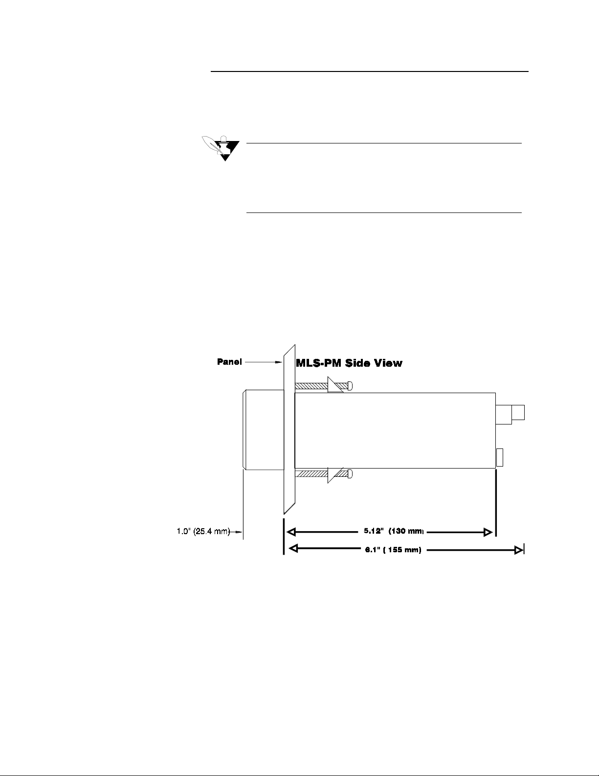
Install the MLS-PM in a location free from excessive (>50 ºC) heat,
dust, and unauthorized handling. The MLS-PM's 1/8 DIN package can
mount in panels up to 0.2" thick . Its dimen sions are 1.8 9" x 3.78" x 6.1"
(48 x 96 x 156 mm), as shown below.
18 MLS User’s Guide
Page 31

MLS-PM Mounting Steps
Installation
1. Use the template below to cut a hole in the panel. Be careful; the
0.02" (0.5 mm) tolerances don't allow much room for error. Use a
punch, nibbler, or jigsaw; file the edges of the hole.
WARNING
Make sure bits of wire and debris do not lodge in
the electronics, or else make sure you clean the
electronics before you connect power.
2. Insert the MLS-PM into the hole through the front of the panel.
3. Screw the top and bottom clips in place. If you expect much panel
vibration, use a rear support for the MLS and its interconnecting
cables.
MLS User’s Guide 19
Page 32

Installation
Mounting the MLS-AIM
This section contains mounting instructions and diagrams for the MLSAIM.
NOTE
If you plan to install scaling resistors, mount them
on the AIM-TB before you mount the AIM-TB in
the panel. (If you mount the AIM-TB in the panel
before you mount the scaling resistors on it, you
will have to remove the AIM-TB from the panel to
install the scaling resistors.)
If you ordered an MLS-AIM-TB with scaling
inputs from Watlow-Anafaze, the scaling resistors
are already installed.
Mounting Environment
Install the MLS-AIM in a location free from excessive (>50ºC) heat,
dust, and unauthorized handling.
The MLS-AIM measures 6.5" x 5 " x 7" (165 x 127 x 1 78 mm). Leave 6 "
of clearance above the MLS-AIM, so yo u can remove the entire unit (or
just the AIM cards) if necessary.
The figure on the next page shows an overhead view of the AIM-TB and
MUX cards, with dimensions, scaling resistor locations and hole
locations. It also shows the AIM communications port and the insertion
of the MUX cards in the AIM Terminal Block.
20 MLS User’s Guide
Page 33
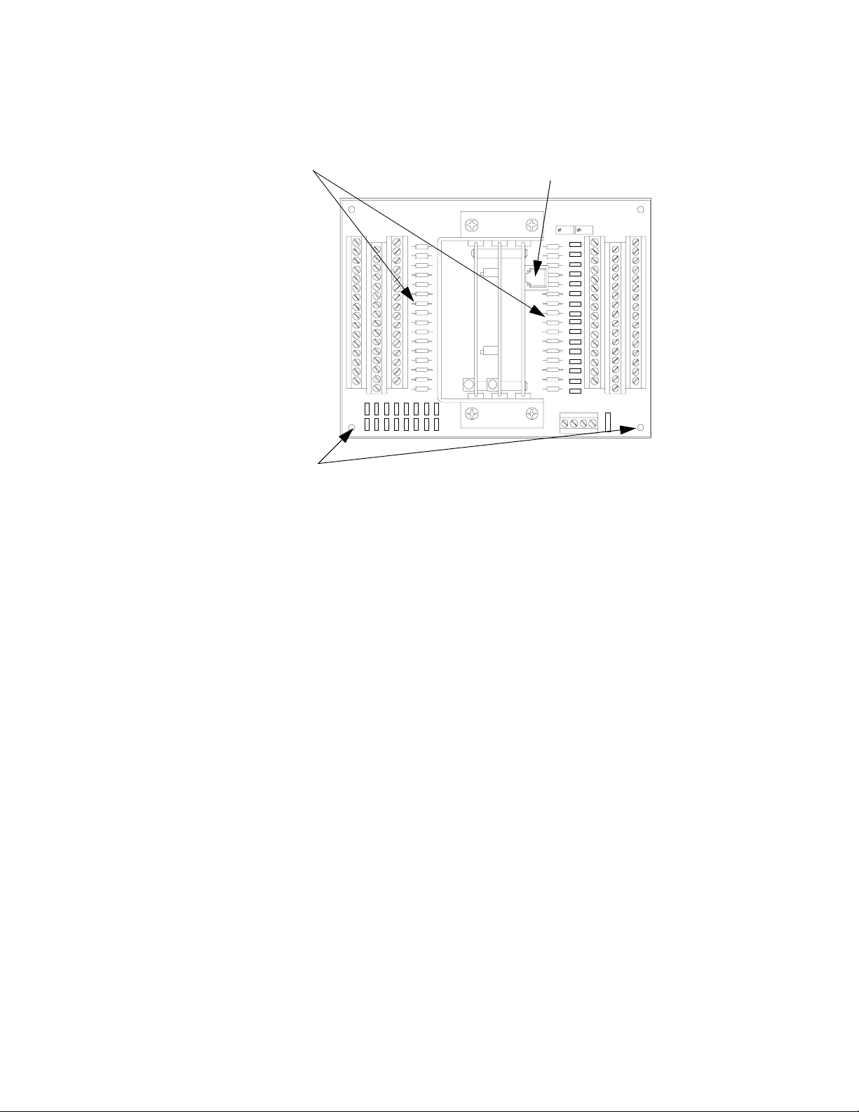
Scaling Resisters AIM Communications Port (Tel. 1)
Installation
Mounting Holes
Mounting Steps
1. Choose an appropriate place to install the MLS-AIM.
2. Place the MLS-AIM where you will mount it and use a pen cil to trace
around the plastic standoffs on the AIM. (If you wish, you can use the
AIM mounting template in the Quick Start foldout to po sitio n the
holes.)
3. Drill four #6 or #8 holes in the chosen location. (#8 holes provide
more clearance.)
4. Place the MLS-AIM where you will mount it. Insert the #6 screws in
the plastic standoffs and tighten them. You may use self-tapping
screws instead, but be sure to remove any loose metal filings after
you are finished mounting the MLS-AIM. Use 3/4" screws with
internal star lock washers to ensure a good Frame Ground connaction.
MLS User’s Guide 21
Page 34

Installation
Mounting the RTB
To mount the RTB, slide it onto a DIN rail. Watlow-Anafaze
recommends Phoenix Contact’s NS32 perforated DIN rail (part number
12-01-00-2). Mount the DIN rail according to Phoenix Contact’s
instructions and slide the RTB onto it.
WARNING
Do not connect power to the MLS now. Test the
unit first, as explained in the Power Wiring and
Controller Test section.
22 MLS User’s Guide
Page 35

Mounting the MLS-PS
Mounting Environment
Mounting Steps
Installation
Follow these instructions to mount the MLS-PS.
If you use your own power supply for the MLS, please refer to the
power supply m anufacturer's instructions for mounting informati on.
Choose a power supply that s upplies a regul ated 7 -28 Vdc at 1 wat t, and
isolated return line.
The MLS-PS measures 1.75" x 8" x 5". Leave enough clearance ar oun d
the power supply that you can remove it later.
The MLS-PS has a bracket at each end of the unit. Each bracket has
three screw holes which will accept #6 or #10 screws. To mount the
MLS-PS, insert screws into the brackets and tighten them.
MLS User’s Guide 23
Page 36
Installation
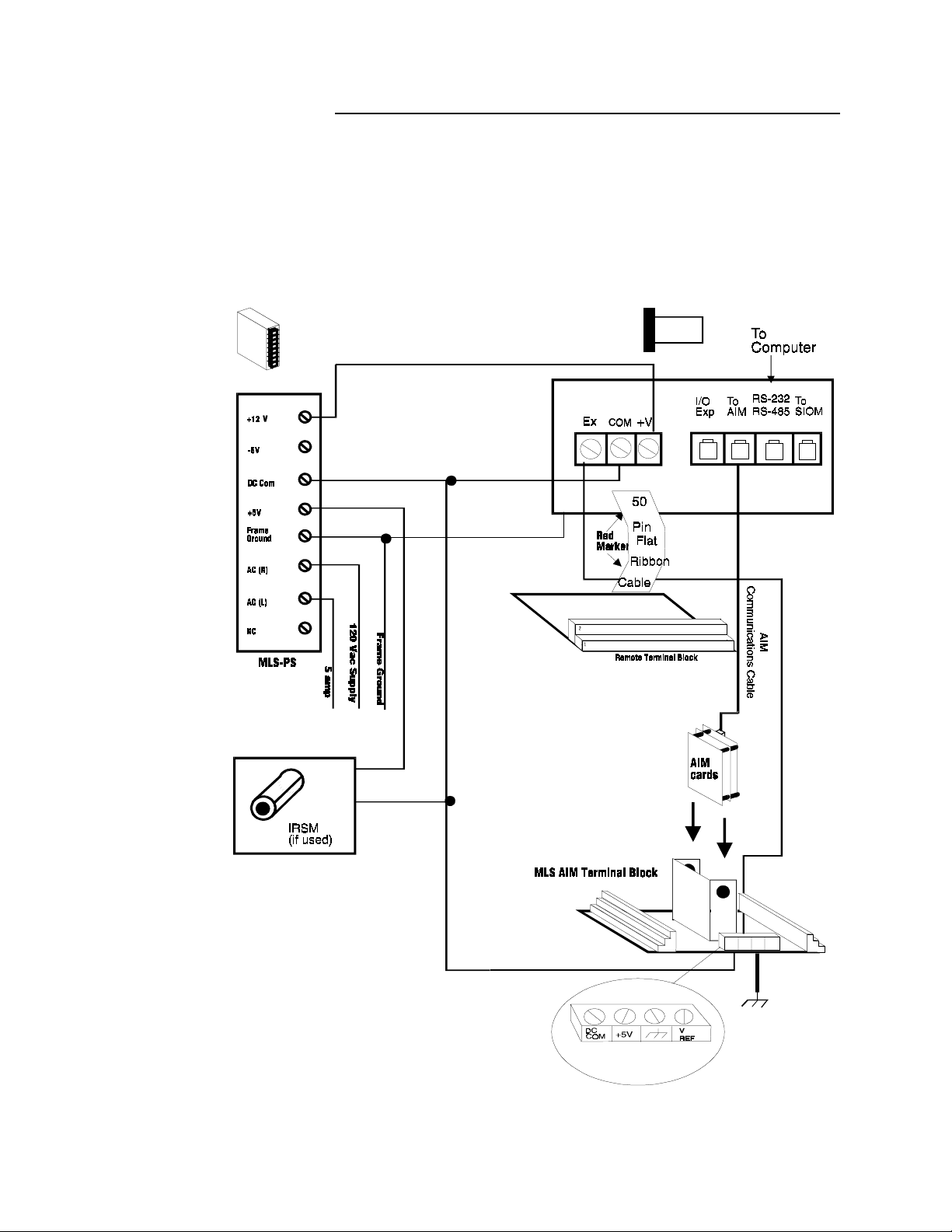
Wiring Your System
This section explains how to wire the components of your system.
Below is the system connections diagram reprinted here for your
convenience. (See the next page for wiring instructions.)
24 MLS User’s Guide
Page 37

Wiring Recommendations
Installation
This section gives general wiring recommendations.
DANGER
Never wire bundles of low power Watlow-Anafaze
circuits next to bundles of high power AC wiring.
Instead, physically separate high power circuits
from the controller. If possible, install high voltage
AC power circuits in a separate panel.
•
Use stranded wire. (Use solid wire for fixed service; it makes inter-
mittent connections when you move it for maintenance.)
•
Use #18 or #20 AWG wire. Larger or smaller sizes may be difficult
to install, may break easily, or may cause intermittent connections.
•
Use shielded wire. (The electrical shield protects the MLS from
electrical noise.) Connect one end of the
MLS panel's 120 Vac panel ground, and connect one end of the
put wiring shield
your system requires a different shield configuration, contact Watlow-Anafaze for more information.)
For more information about noise supp res sion , see
to the MLS panel's 120 Vac panel ground. (If
input wiring shield
Noise Suppression
to the
out-
.
MLS User’s Guide 25
Page 38

Installation
Cable Recommendations
Use these cables or their equivalent.
Function MFR P/N No. of Wires AWG
Analog Inputs Belden #9154
Belden #8451
RTD Inputs Belden #8772
Belden #9770
T/C Inputs T/C Ext. Wire 2 20
Carbon Probe Input Belden #88760 2 18
Digital PID Outputs and Digital
I/O
Analog Outputs Belden #9154
Computer Communication:
RS232, RS422, RS485, or 20
ma
Belden #9539
Belden #9542
Ribbon Cable
Belden #8451
Belden #9729
Belden #9730
Belden #9842
Belden #9843
2
2
3
3
9
20
50
2
2
4
6
4
6
20
22
20
22
24
24
20
22
24
24
24
24
Noise Suppression
If the MLS outputs control dry-contact EM relays with inductive loads-like alarm horns and motor starters--you may get Radio-Frequency
Interference (RFI, or "noise") This section explains how to avoid noise
problems; read it before you wire the MLS.
Symptoms of RFI
•
The MLS display blanks out and then reenergizes, as if power had
been turned off for a moment.
•
The process value does not display correctly.
•
The MLS CPU may reset; if it does, it loses its' PID output levels.
RFI may also damage the di gital output circuit--so digital outputs will
not energize. If the digital output circuit is damaged, return the
controller to Watlow-Anafaze for repair.
Avoiding RFI
Where possible, use solid state relays (SSRs) instead of electricalmechanical (EM) relays. If you must use EM relays, try to avoid
mounting them in the same panel as Watlow-Anafaze equipment.
Separate the 120 Vac power leads from the low level input and output
leads connected to the MLS. Don't run the digital output or PID control
output leads in bundles with 120 Vac wires. (Never run input leads in
bundles with high power leads--see the
General Wiring
section.)
26 MLS User’s Guide
Page 39

If you must use EM relays and you must place them in a panel with
Watlow-Anafaze equipment, use a .01 microfarad capacitor rated at
1000 Vac (or higher) in series with a 47 ohm,
normally open (NO) contacts of the relay load. This network is known
as an arc suppressor or snubber network.
You can use other voltage suppression devices, but they are not usually
required. For instance, you can place a metal oxide varistor (MOV)
rated at 130 Vac for 120 Vac control circuits across the load, which
limits the peak AC voltage to about 180 Vac. You can also place a
transorb (back to back zener diodes) across the digital output, which
limits the digital output loop to 5 Vdc. (You can get these parts from
Watlow-Anafaze.)
The above steps will eliminate most noise problems . If you have fu rther
problems or questions, please contact Watlow-Anafaze.
Wi ring and Testing Your System
Installation
½
watt resistor across the
After you install each component of the MLS, use this section to
connect them. If these instructions are not clear to you, refer to the
system connections diagram for more information. (These instructions
are written for non-electricians. If you are an experienced electrician,
they may seem elementary to you. If so, feel free to skim them.)
When you have connected each component of your system, install and
connect input and output devices. For help with inputs and outputs, see
the Outputs and the Inputs sections in this chapter.
Connecting Power and RTB to MLS-PM
1. Remove the temporary covers you placed on the MLS' housing.
2. Connect the power supply terminal labeled "DC COM" to the terminal labeled "GND" on the Processor Module. This terminal is DC
common; it is not frame, chassis or earth ground.
3. Connect the power supply terminal labeled "+12V" to the terminal
labeled "+V" on the Processor Module.
4. Connect the 50-pin ribbon cable to the Processor Module. Plug it in
so that the red stripe is on the left side, under TB1.
5. Connect the ribbon cable to the RTB. Plug it in so that the red stripe is
closest to screw terminal 1.
Connecting Power and Common to AIM-TB
1. Connect the terminal labeled "EX" on TB1 of the MLS-PM to the terminal labeled "+5V" on the MLS-AIM.
2. Connect the terminal labeled "COM" on TB1 of the MLS-PM to the
MLS-AIM terminal labeled "DC COMMON".
MLS User’s Guide 27
Page 40
Installation
Testing Connections
3. Plug the AIM communications cable into the slot on the MLS-PM
labeled "To AIM".
4. Plug the other end of the AIM communications cable into the sl ot on
the MLS-AIM labeled "Tel 1". (The slot is on top of the V/F card.)
WARNING
Do not turn on the AC power now. Test the connections first, as explained below.
5. Connect AC power wires to the MLS-PS.
6. Connect " " terminal on MLS AIM to frame Ground.
WARNING
Reversed polarity or incorrect voltage to the PM
or AIM will damage your MLS, and y ou will need
to return it to Watlow-Anafaze for repair. Please
don't damage your unit! Read this section completely and follow the steps below before you apply
power to your MLS.
1. Unplug TB 1 (the green block which contains the Ex, GND, and +V
terminals) from the MLS-PM.
2. Unplug the AIM cards from the AIM-TB:
•
Carefully insert a screwdriver in the hole on the side of the AIM's
metal jacket.
•
Gently press the screwdriver blade against the metal standoffs which
separate the AIM cards.
•
Continue pressing gently until the AIM cards pop loose from the
plastic bracket that holds them in place. Then, carefully grasp the
AIM cards by the edges and remove them from the metal bracket.
You have removed the parts of the MLS which will be
damaged by excess voltage, so turn on the AC power
and use a voltmeter to check voltages:
3. Touch the meter Common lead to the "COM" terminal on the MLSPM (the green block with the wires). The voltage on the "+V" terminal of the MLS-PM should be +10 to 28 Vdc. The voltage on the
"EX" terminal of the MLS-PM should read 0 Vdc.
4. If the voltages are within the limits described above:
•
Turn off the power.
•
Plug TB1 (the green block which contains the screw terminals) back
into the MLS-PM.
28 MLS User’s Guide
Page 41

Installation
•
Turn the power back o n. The Processor Mo dule's display should light
up, and after about a second the Bar Graph display should appear,
followed by the message "AIM COMM FAIL".
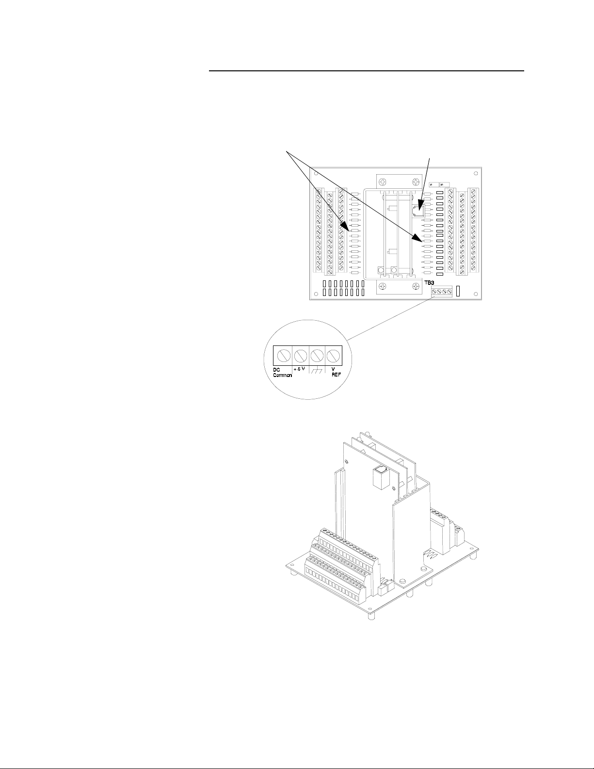
5. Connect the Common lead of the voltmeter to TB3 and the power
lead of the voltmeter to the AIM-TB terminal labeled "+5V". The
voltage on the "+5V" terminal should be between +4.75 and +5.25
Vdc.
6. If the voltages are within the limits described above:
A. Turn off the power.
B. Carefully insert the AIM cards back into the AIM Terminal
Block.
C. If you have unplugged the AIM COMM. cable, plug it back in.
D. Press and hold the No key. While pressing it, turn the power
back on. (This procedure is known as a manual controller reset
or No Key reset.)
The green LEDs on the AIM should blink, which means that the
unit is working normally. If they do not blink, contact Watlow-
Anafaze.
E. The MLS-PM will display a "T/C Break" alarm message for
each channel. These messages are normal; to clear them, press
Alarm Ack once for each control loop.
MLS User’s Guide 29
Page 42

Installation
Testing Your System
MLS-AIM Test
This section explains how to test the controller after installation.
Use this procedure to test the MLS-AIM before you connect inputs to it.
1. Connect a wire from the A+ terminal for loop 1 to the A- terminal for
loop 1.
2. Turn on power to the MLS-PM.
3. Press the
on the MLS-PM's screen.
4. Press the
MLS-AIM-TB contains an ambient temperature sensor, so Loop 1
should display room temperature. If it does not, contact WatlowAnafaze.
ALARM ACK
YES
key to reach the single loop display for Loop 1. The
key to clear the alarm messages displayed
RTB Test
PID Output Test
1. Turn on power to the MLS.
2. Measure the +5Vdc supply at the RTB:
A. Connect the voltmeter's Common lead to RTB terminal #3.
B. Connect the voltmeter's Power lead to RTB screw terminal #1.
The voltage should be 4.75 to 5.25 Vdc.
C. Connect the Power lead to RTB screw terminal #2. The voltage
should be 4.75 to 5.25 Vdc.
D. Connect the Power lead to RTB screw terminal #4. The voltage
should read 0 volts.
1. Connect the voltmeter power lead to RTB screw terminal #1.
2. Connect the Common lead to the PID output pin.
3. If you have not connected a load to the output, connect a 500 ohm to
100 Kohm resistor b etween RTB screw terminal 1 and the PID output
pin.
4. Use the digital output test (in the Manual I/O Test menus) to turn the
digital output on and off. When the output is off, the output voltage
should be less than 1V. When the output is on, the output voltage
should be between 3.75 and 5.5V.
30 MLS User’s Guide
Page 43

Outputs
Installation
NOTE
Your ML S is shipped wit h heat outputs e nabled
and cool outputs disabled. You can disable any PID
output and use it for other digital output functions.
All digital outputs and PID outputs are sink outputs referenced to the 5Vdc supply. These outputs
are Low when they are On.
All digital inputs are Transistor-Transistor Logic
(TTL) level inputs referenced to control common.
This section discusses the MLS' PID control and alarm outputs.
WARNING
Control outputs are connected to the MLS's logic
ground when the control output is On (Low). Be
careful when you connect external devices that
may have a low side at voltage other than controller ground, since you may create ground loops.
If you expect grounding problems, use isolated
solid state relays and isolate the control device
inputs.
The MLS provides dual PID control outputs for each loop. These
outputs are on the 50 pin ribbon cable connector which connects to the
RTB. You can enable or disable them.
•
The default setting is heat outputs enabled, co ol outputs disabled.
•
You can program each output for on/off, TP, or DZC control.
•
You can program each output for direct or reverse action.
•
You can program a deadband for heat/cool; within that deadband
both outputs will be Off.
Output Wiring Recommendations
When you wire output devices to the RTB, use multicolored stranded
shielded cable for analog outputs and PID digital outputs connected to
panel mount SSRs.
•
Analog outputs usually use a twisted pair.
•
Digital outputs have 9 to 20 conductors, depending on wiring tech-
nique.
MLS User’s Guide 31
Page 44

Installation
Ribbon Cable Recommendations
Use the 50-pin connector for both ends of the 50 pin flat ribbon cable.
(Do not connect either end to a screw terminal; the cable wire is too
small to withstand much flexing.)
Do not exceed 15' of 50-conductor cable.
Using the Cable Tie Wraps
When you have wired outputs to the TB-50, ins tall the cable tie wraps
shipped with it. This diagram shows the cable tie wrap holes.
Each row of terminals has a cable tie wrap hole at one end. Thread the
cable tie wrap through the cable tie wrap hole. Then wrap the cable tie
wrap around the wires attached to that terminal block.
32 MLS User’s Guide
Page 45

PID Control and Alarm Output Connections
T ypical digital control outputs use external optically-isolated solid-state
relays (SSRs). The SSRs use a 3 to 32 Vdc input for control, and you
can size them to switch up to 100 amps at 480 Vac. For larger currents,
use these optically-isolated relays to drive contactors.
NOTE
Control outputs are sink outputs. They are Low
when the output is O n. Connec t them t o the neg ative side of Solid State Relays.
The next figure shows sample heat/cool and alarm output connections.
Installation
System Safe (Watchdog Timer) constantly monitors the MLS CPU. It is
a SINK output located on RTB terminal #6. (Do not exceed the 10
mAdc rating for the System Safe output.) Its output is Low (on) when
the CPU is operating; when it stops operating, the output goes High
(off), de-energizing the SSR.
Here's the recommended circuit for the System Safe output:
+5 Vdc
(RTB pin 2)
+
SSR
System safe
(RTB pin 6)
_
MLS User’s Guide 33
Page 46

Installation
RTB Connections
Connect outputs to the RTB as shown in the table below.
Terminal Function PID Output Terminal Function PID Output
1 +5 Vdc 2 +5 Vdc
3 CTRL COM 4 CTRL COM
5 Spare 6 System Safe
7 Pulse input 8 Global Alarm
9 DIG Output 1 Heat 1 10 DIG Output 34*
11 DIG Output 2 Heat 2 12 DIG Output 33 Pulse Loop Heat
13 DIG Output 3 Heat 3 14 DIG Output 32 Heat 32/Cool 16
15 DIG Output 4 Heat 4 16 DIG Output 31 Heat 31/Cool 15
17 DIG Output 5 Heat 5 18 DIG Output 30 Heat 30/Cool 14
19 DIG Output 6 Heat 6 20 DIG Output 29 Heat 29/Cool 13
21 DIG Output 7 Heat 7 22 DIG Output 28 Heat 28/Cool 12
23 DIG Output 8 Heat 8 24 DIG Output 27 Heat 27/Cool 11
25 DIG Output 9 Heat 9 26 DIG Output 26 Heat 26/Cool 10
27 DIG Output 10 Heat 10 28 DIG Output 25 Heat 25/Cool 9
29 DIG Output 11 Heat 11 30 DIG Output 24 Heat 24/Cool 8
31 DIG Output 12 Heat 12 32 DIG Output 23 Heat 23/Cool 7
33 DIG Output 13 Heat 13 34 DIG Output 22 Heat 22/Cool 6
35 DIG Output 14 Heat 14 36 DIG Output 21 Heat 21/Cool 5
37 DIG Output 15 Heat 15 38 DIG Output 20 Heat 20/Cool 4
39 DIG Output 16 Heat 16 40 DIG Output 19 Heat 19/Cool 3
41 DIG Output 17 Heat 17/Cool 1 42 DIG Output 18 Heat 18/Cool 2
43 DIG Input 1 44 DIG Input 2
45 DIG Input 3 46 DIG Input 4
47 DIG Input 5 48 DIG Input 6
49 DIG Input 7 50 DIG Input 8
* If you install an Watlow-Anafaze Serial Digital to Analog Converter (SDAC), the MLS uses digital output #34
for a clock line. You cannot use output #34 for anything else when an SDAC is installed.
34 MLS User’s Guide
Page 47

AIM Communications Failure
The controller continuously checks communications between the MLSPM and the AIM. If communication stops for more than five seconds,
the MLS-PM display indicates AIM COMM FAIL, the PID mode
changes to manual, and the controller sets every output to the output
override percentage.
WARNING
PID outputs remain in manual mode after an AIM
communications failure. After an AIM failure,
change the PID control status back to automatic
mode for each control loop.
An AIM communications failure also activates the global alarm output.
If you have selected a digital output from the Global Parameters menu,
an AIM communications failure also activates the output.
Installation
MLS User’s Guide 35
Page 48
Installation
Inputs
This figure shows the AIM cards (also known as the MUX cards) and
AIM-TB, with scaling resistor locations.
Scaling Resisters AIM Communications Port (Tel. 1)
36 MLS User’s Guide
•
The loop input number is marked on the terminal block: the number
1 indicates an input for loop 1, the n umber 2 an input for loop 2, etc.
•
The A+ terminal is the positive input of the analog signal.
•
The A- terminal is the negative input of the analog signal.
Page 49

•
The A COM (AUX) terminal is the Auxiliary input. This is an alog
WARNING
Do not exceed 10 Vdc between loops. Excess voltage may damage the Analog Input Module (AIM).
Input Wiring Recommendations
Use multicolored stranded shielded cable for analog inputs. WatlowAnafaze recommends that you use #20 AWG wire. (If the sensor
manufacturer requires it, you can also use #22 or #24 AWG wiring.)
Most inputs use a shielded twisted pair; some require a 3-wire inpu t.
Input Scaling
Installation
common used for RTD inputs.
Y ou can co nnect thermocouples, 4-20 mA current inputs, vo ltage inputs,
and 2- or 3- wire RTD inputs to the MLS. If you need to scale input
voltages or convert milliamp inputs to match the -10 to 60 mV (-16.7%
to 100%) input range, install scaling resistors. Watlow-Anafaze can
supply factory-installed input scaling resistors--order option MLS-SIXX (See the next table for standard scaling resistor values), or special
input kits MLS-SIK-XX (call Watlow-Anafaze for XX number).
Scaling Values
•
Scaling values for mVdc ranges are standard metal film values with
0.25% accuracy if 0.1% tolerance resistors are used.
+
•
Scaling values for mAdc ranges are 0.1% tolerance with +0.10%
accuracy.
•
Scaling values for RTD ranges are 0.05% tolerance. Use these values
to remain within factory specifications for the RTD inputs.
•
Use 0.1% metal film, 1/4 watt resistors. Higher tolerances may cause
significant errors. Use the MLS' built-in linear scaling to correct
any errors due to resistor tolerance. You can also install other components (like capacitors) for signal conditioning; please consult
Watlow-Anafaze for more information.
This figure shows an input circuit. RA, RB, RC, and RD refer to the
scaling resistor locations printed on the MLS-AIM's terminal board.
MLS User’s Guide 37
Page 50
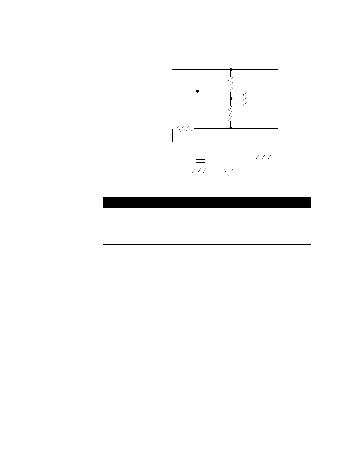
Installation
To
MLS-AIM
Circuitry
RD
C .47 uF
A +
A -
A COM
Analog
Input
Terminal
Internal
+2.5 Vdc
Reference
RC
RA
RB
C .47 uF
This table shows scaling resistor values.
Input Range RA RB RC RD
All T/C, 0-60 mVdc Jumper
RTD1 -100.0 to 300.0
º
RTD2, -120 to 840
RTD3, -70 to 300
C
º
C
0-10 mAdc
0-20 mAdc (4-20 mA)
0-100 mVdc
0-500 mVdc
0-1 Vdc
0-5 Vdc
0-10 Vdc
0-12 Vdc
º
C
5.49K
11.0K
11.0K
-450 to
2500
5.49K
11.0K
11.0K
80
100
100
Jumper
Jumper
499
5.49K
6.91K
39.2K
49.9K
84.5K
IN +
IN -
6.0
3.0
750
750
422
475
301
422
38 MLS User’s Guide
Input Calibration
The MLS provides offset calibration for T/C, RTD, and other fixed
ranges. It also provides offset and span (gain) calibration for linear and
pulse inputs. (Offset and span calibration convert linear analog inputs
into engineering units using the Mx+B function.) The offset range is 300 to +300 units; the magn itude of the of fs et depen ds on the inp ut ty pe
and span you select.
Follow these steps to use the MLS' offset and span calibration:
1. Install scaling resistors that will provide an appropriate full scale voltage. (If you have any doubts about your ability to install scaling resistors, contact W atlow-An afaze.)
Page 51

T/C Inputs
Installation
2. Select the # of digits and decimal point location for the full scale PV
display. The smallest possible range is -0.9999 to +3.0000; the largest
possible range is -9999 to 30000.
3. Enter the zero and full scale values (process variables) you want displayed when the input signal is at zero and full scale.
WARNING
Use ungrounded thermocouples (thermocouples
which have the T/C junction isolated from the
metal protection sheath). Grounded thermocouples will damage the MLS if voltage between the
loops exceeds 10 volts.
If you are installing the MLS in an existing temperature control system, check all grounded T/C
assemblies in the system. Make sure there is no
voltage between T/C leads.
You can connect all T/C types directly to the MLS. Watlow-Anafaze
provides J, K, T, R, S, and B type linearization and cold junction
compensation. (Other thermocouple types require custom input ranges;
contact Watlow-Anafaze for more information about them.)
Wiring Recommendations
Follow these recommendations for thermocouple wiring:
•
Use 18 or 20 AWG thermocouple (T/C) extension wire for all ther-
mocouple inputs.
•
Most T/C wire is solid unshielded wire. Use shielded wire if required
at your installation; ground one end only.
•
Use less than 500' of T/C extension wire. Longer wire runs exceed
accuracy and source impedance specifications.
•
Install T/C wiring in a separate conduit away from AC power (the
120 Vac supply) and high power (240 Vac or higher) wiring.
MLS User’s Guide 39
Page 52
Installation
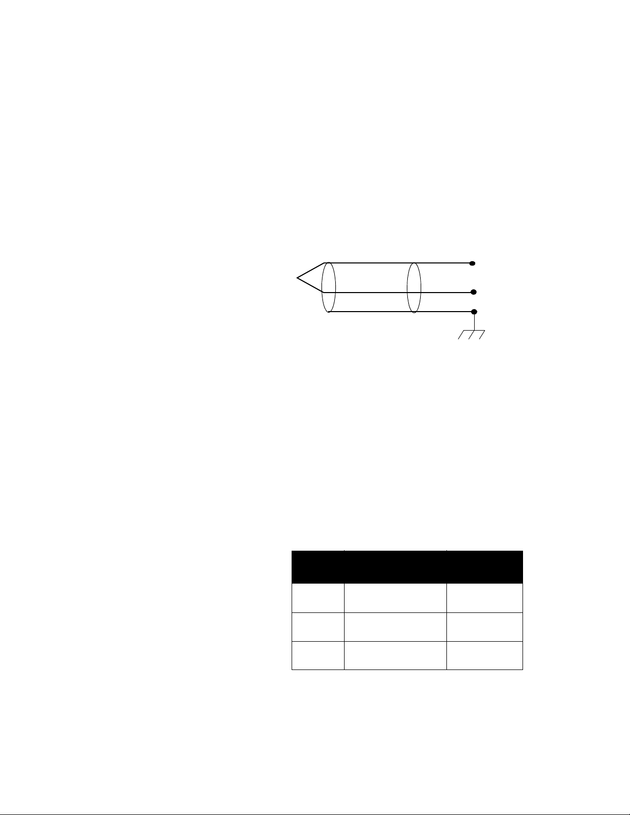
Connecting Thermocouples
Connect the positive T/C lead to the A+ terminal. Connect the negative
T/C lead to the A- terminal of TB1. The figure below shows a typical
thermocouple connection.
•
Use 20 gauge T/C extension wire for all T/C inputs.
•
If you use shielded wire, tie the shield to panel ground.
•
Install a jumper or zero ohm resistor in location RC on the AIM-TB
if it had been removed.
This figure shows a typical thermocouple connection.
RTD Inputs
White
Type J T/C
The standard industrial RTD is an 100 ohm, three-wire, platinum
assembly as shown in the next figure. Watlow-Anafaze highly
recommends that you use the three-wire RTD to prevent reading errors
due to cable resistance.
•
If you order an RTD1, RTD2, or RTD3 configuration, we will con-
figure your MLS for the standard three-wire RTD.
•
If you must use a two-wire RTD, jumper A- to AUX.
•
If you must use a four-wire RTD, do not connect the fourth wire.
Watlow-Anafaze offers three standard DIN 385 curve RTD input
ranges, as shown in the table below:
Red
Shield
IN +
IN
–
40 MLS User’s Guide
RTD
Type
RTD1 -100.0 to 300.0 C
RTD2 -120 to 840 C
RTD3 -70 to 300 C
This figure shows a typical 3-wire RTD connection.
Input Range
-148.0 to 572.0 F
-184 to 1544 F
-94 to 572 F
Resolution
0.1 C
0.1 F
1 C
1 F
1 C
1 F
Display
Page 53

Current Inputs
Voltage Inputs
Installation
Rear Terminal Block
Connections
Black
100 Ohm RTD
Black
Red
IN +
–
IN
Analog Common
To install current (milliamp) inputs, place resistors in the input section
which convert the milliamp input into a voltage. (You can get different
current input ranges if you select different resistor values.) The input
connections for these inputs are the same as the input connections for
voltage inputs.
Unused Inputs
Connect the + side of the voltage input to the A+ terminal. Connect the side of the input to the A- terminal. The voltage input range is -10 to 60
mV. Scale signals larger than 60 mV with a scaling resistor which makes
full scale input 60 mV.
The next figure shows two resistors. RA and RB are not loaded. RC is
the voltage reducing or current limiting resistor, and RD is the 60 mV
full scale dropping resistor. RD is normally less than 500 ohms, and it
should never exceed 1000 ohms.
To
Circuitry
IN +
RD
–
IN
RC
Set the input type for unused inputs to "SKIP" to avoid the default T/C
break alarms.
MLS User’s Guide 41
Page 54

Installation
Communications
The MLS is factory-configured for either RS-232 or RS-485
communications. When you order your un it, specify the type of
communications you need.
•
If you use one MLS and you connect it to a computer less than 50
feet away, you can use RS-232 communications.
•
If you use more than one comp uter, or if the computer and controller
are more than 50 feet apart, use RS-485 communications.
PC-compatible computers typically use RS-232 communications. If the
MLS is configured for RS-232 communications, you can connect it
directly to the serial communications connector on an IBM-PC or
compatible computer.
If you use RS-485 communications, attach an optically isolated RS-232/
RS-485 converter to the computer. You can use an internal converter
card or an external plug-in converter.
Changing Communications
Follow these instructions to change the unit's communications between
RS-485 and R S -232:
1. Unplug any cables connected to the MLS-PM.
2. If you already installed the MLS-PM in a panel, remove it from the
panel.
3. Unscrew the screws on the PM's casing. (There are either two or four
screws on the sides of the casing. There are two additional screws on
the top of the casing.)
4. Move jumpers JU2, JU4, and JU14 on the upper PC board.
5. If you are changing communications for the last unit on the serial
communications line, also m ov e jumper JU3. Installing this jumper
places a 200 ohm impedance on the line.
6. Reverse instructions 1-3 to reinstall the unit.
Connecting RS-232 Communications
The RS-232 interface is a standard phone cable with a 6-pin male phone
connector on one end and a 9- or 25-pin D-sub female connector on the
computer end. (You can order this cable--called an MLS COM cable-from Watlow-Anafaze. If you order it, specify the length of cable and
the type of D-sub miniature connector you need.)
42 MLS User’s Guide
Page 55
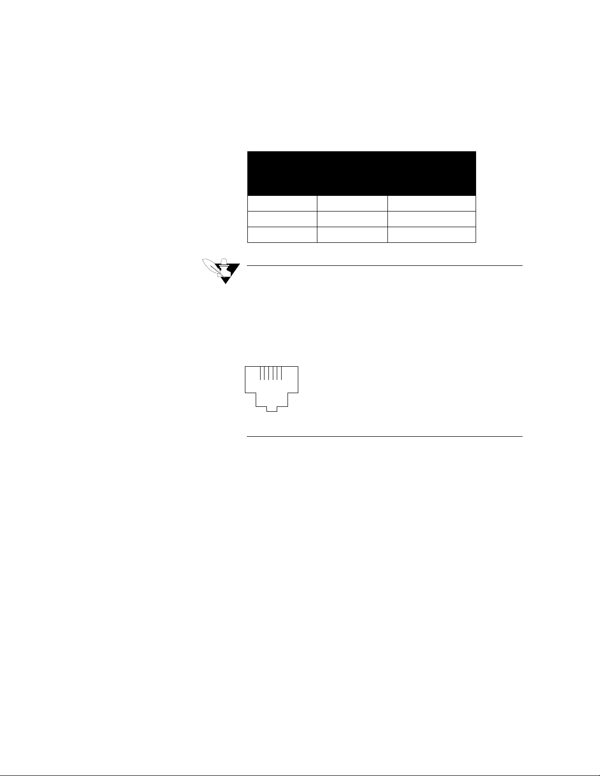
Installation
1. Plug the phone connector into the slot labeled "RS-232/RS-485" on
the rear of the MLS-PM.
2. Plug the D-sub connector into the communications connector.
This table shows RS-232 connections for 25-pin and 9-pin connectors.
Computer Connector
DB 25 DB 9
RX Pin 3 RX Pin 2 TX Pin 5 Ye llow
TX Pin 2 TX Pin 3 RX Pin 1 Blue
GND Pin 7 GND Pin 5 GND Pin 4 Green
MLS RS-232 Pin
Number
NOTE
The pin numbers and colors are not industry standard. Watlow-Anafaze numbers the pins from
right to left with 1 on the right as you’re looking at
the back of the MLS-PM. Colors vary depending
on the manufacturer. The figure below shows a
back of an MLS-PM.
16
Connecting RS-485 Communications
RS-485 specification is for "balanced line" operation; it is not true
differential, so you must supply a common ground connection. Use a
fifth wire (which should not b e shi eld, i f pos sible) or a commo n groun d
connection to establish the common ground.
Do not use the common ground connection unless the common mode
voltage between stations at your installation exceeds the RS-485
specification of 7 volts peak; in that case, use a fifth wire.
The following diagram shows the recommended system hookup. The
transmitter from the host computer connects in parallel to the controller
receivers, and the host computer receiver connects in parallel to the
controller transmitters. Watlow-Anafaze recommends that you use a
single "daisy chain" rather than "octopus connections" or "spurs". In
addition, use a terminating resistor (a 200 ohm resistor lai d acros s the
line at the furthest point from the transmitter) at each end of the
transmission line.
This figure shows the MLS RS-485 connections.
MLS User’s Guide 43
Page 56
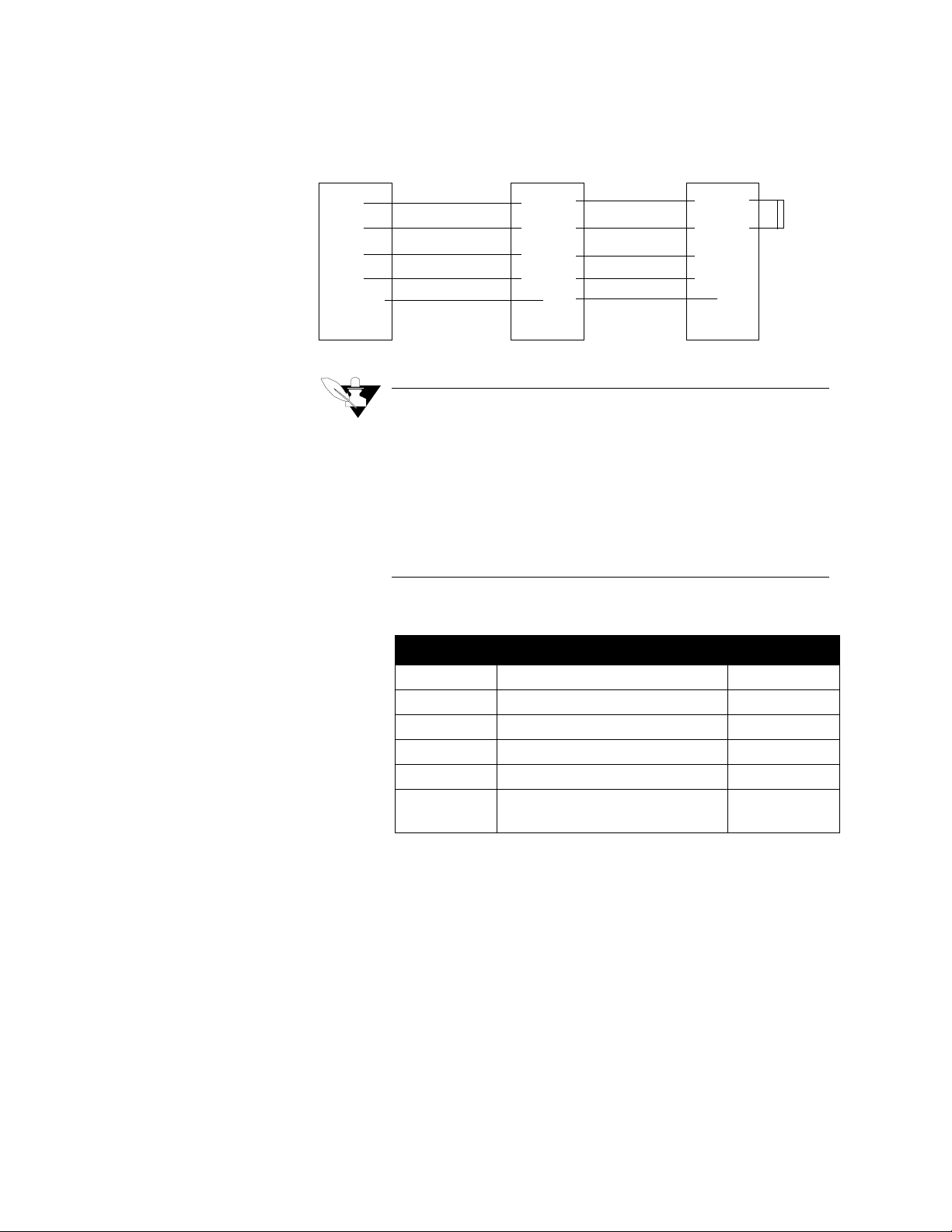
Installation
Black Box
LD 485
A
TXA
TXB
RXA
RXB
Ground
MLS T3A/B
[n] RJ12
RX+ #3
RX- #1
TX+ #2
TX- #5
#6
Red
Blue/White
Black
Yello w
Silver
MLS T3A/B
[1] RJ12
RX+ #3
RX- #1
TX+ #2
TX- #5
#6
Red
Blue/White
Black
Yello w
Silver
NOTE
Connect the shields to earth ground only at the
computer or other 485 interface. Do not connect
the shield at the MLS. Connect a 200 ohm terminating resistor between RX- and RX+ at the last
MLS (Ju3).
The loop resistance of the transmission line (wire
only, not terminating resistor) must not exceed 200
ohms.
200
Ω
This table shows RS-485 connections.
Line RS-485 Connection Color
TXB RX+Pin 1 Blue/White
TXA RX-Pin 3 Red
RXB TX+Pin 5 Yellow
RXA TX-Pin 2 Black
Ground Pin 4 Green
Shield Shield Pin 6
(Not jumpered internally)
EIA Standard RS-485 specifies the electrical characteristics of
transmitters and receivers for digital multi-point systems. WatlowAnafaze equipment meets RS-485 and RS-422 standard s. Ho wever, RS485 does not specify transmission lines, signaling rates, protocols, etc.
Watlow-Anafaze recommends the following:
•
Maximum signaling rate: 9600 baud.
•
Twisted shielded pairs for the RS-485 cab les.
44 MLS User’s Guide
Page 57

Recommended Wire Gauges
Installation
This table shows maximum distances and wire gauges for
communica tions wiring:
Distance Wire Gauge Recommended Cable
4000 ft. 24 AWG Belden #9729
Belden #9842
6000 ft. 22 AWG Belden #9184
You may wish to use a shield, dependin g on your noi se envi ronment and
grounding problems. These cables are shielded.
MLS User’s Guide 45
Page 58

Installation
46 MLS User’s Guide
Page 59
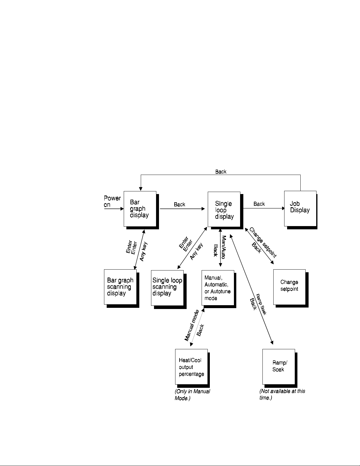
Using the MLS
This chapter explains how to use the front panel to operate the
controller. (If you are using ANASOF T, see the operation instructions in
the ANASOFT User's Guide.) The next figure shows a map of the
operator menus and displays accessible from the MLS Controller's front
panel. You don't need to enter a passkey sequence to reach these menus.
To make detailed changes to global parameters, loop inputs, control
parameters, outputs, and alarms via the setup menus, you must enter a
special sequence of keys. (F or m ore i n form at io n about the Setup menus ,
Chapter 4: Setup
see
Using the MLS
.)
MLS User’s Guide 47
Page 60

Using the MLS
Front Panel
Man/Auto
Changes loop output
control from Automatic
to Manual or Tune
Assigns output power
level of manual loops
Change Setpoint
Changes process
Setpoint
The MLS front panel provides a convenient interface with the
controller. You can use the front panel keys to program and operate the
MLS, or you can use ANASOFT, a program designed specifically for
ANAFAZE controllers. (See the
ANASOFT User's Guide
for more
information about ANASOFT, or contact ANAFAZE.)
This figure shows the MLS' front panel.
Ramp/Soak
Not available
at this time
Alarm Ack
Acknowledges
Enter
Stores data or me nu
yes
Selects a menu
Answers Yes
to Ye s/No prompts
Increases a number
or choice
Back
Aborts editing
and returns
to a previous
menu
choices & advances to
the next menu
Starts scanning mode
(if pressed twice)
No
Skips a menu
Answers No to Yes/No
prompts
Decreases a number or
choice you are editing
48 MLS User’s Guide
Page 61

Front Panel Keys
Yes (Up)
No (Down)
Yes
Press
•
•
•
•
to do these things:
Select a menu.
Answer Yes to Yes/No prompts.
Increase a number or choice you're editing.
Stop scanning mode.
Using the MLS
Back
Press No to do these things:
•
Skip a menu when the prompt is blinking.
•
Answer No to Yes/No prompts.
•
Decrease a number or choice when editing.
•
Stop scanning mode.
•
Perform a manual controller (No Key) reset (see next page).
WARNING
A manual controller (No Key) reset clears the controller's RAM and reinitializes the MLS-PM's
factory default values.
A manual controller reset is appropriate in these situations:
•
After you change the PROM.
•
In some cases when troubleshooting (see
ing
).
Chapter 6: Troubleshoot-
Back
The
•
•
•
key works like an "escape" key. Press it to:
Abort editing.
Return to a previous menu.
Stop scanning mode.
MLS User’s Guide 49
Page 62

Using the MLS
Enter
Chng SP
Man/Auto
•
Switch between Bar Graph and Single Loop display.
Press the "Enter" key to:
•
Store data or a menu choice after editing.
•
Go on to the next menu.
•
Start scanning mode (if pressed twice).
•
Press this key to change the loop setpoint.
Ramp/Soak
Alarm Ack
Press the Man/Auto key to:
•
Toggle a loop between manual and automatic control.
•
Adjust the output power level of manual loops.
•
Automatically tune the loop.
Ramp/Soak isn't available for the standard MLS. When pressing this
key, a message appears: OPTION UNAVAILABLE.
Press Alarm Ack to:
•
Acknowledge an alarm condition.
•
Reset the global alarm digital output.
50 MLS User’s Guide
Page 63

Displays
LOOP PROCESS UNITS
ALARM SETPOINT STATUS OUT%
This section describes the MLS' displays.
Viewing Several Loops: Bar Graph Display
When you connect power to the MLS, it displays general symbolic
information for loops 1-8. This display is called Bar Graph mode. The
next figure shows a picture of the Bar Graph display.
01 08
AAAA MAMA
This table explains the symbols on the to p line of the Bar Graph display.
Using the MLS
Symbol Symbol’s Meaning
<
>
Loop is in low process or low deviation alarm.
Loop is in high process or high deviation alarm.
Loop is above setpoint. If you enable the high or low devia-
tion alarm, this symbol is scaled to it. If you don’t enable
these alarms, these symbols are scaled to the setpoint +
the sensor’s range.
Loop is at setpoint. If you enable the high or low deviation
alarm, this symbol is scaled to it. If you don’t enable these
alarms, these symbols are scaled to the setpoint +
5% of the
sensor’s range.
Loop is below setpoint. If you enable the high or low devia-
tion alarm, this symbol is scaled to it. If you don’t enable
these alarms, these symbols are scaled to the setpoint +
the sensor’s range.
Blank
(
) Loop is set to SKIP.
F
Sensor has failed.
The next table explains the symbols you see on the bottom line of the
Bar Graph display and in the Single Loop display. These symbols
appear when the controller is in bot h dual ou tput mode and s ingle ou tput
mode. If the process goes into alarm, the controller automatically
switches to Single Loop display and shows an alarm code.
5% of
5% of
MLS User’s Guide 51
Page 64
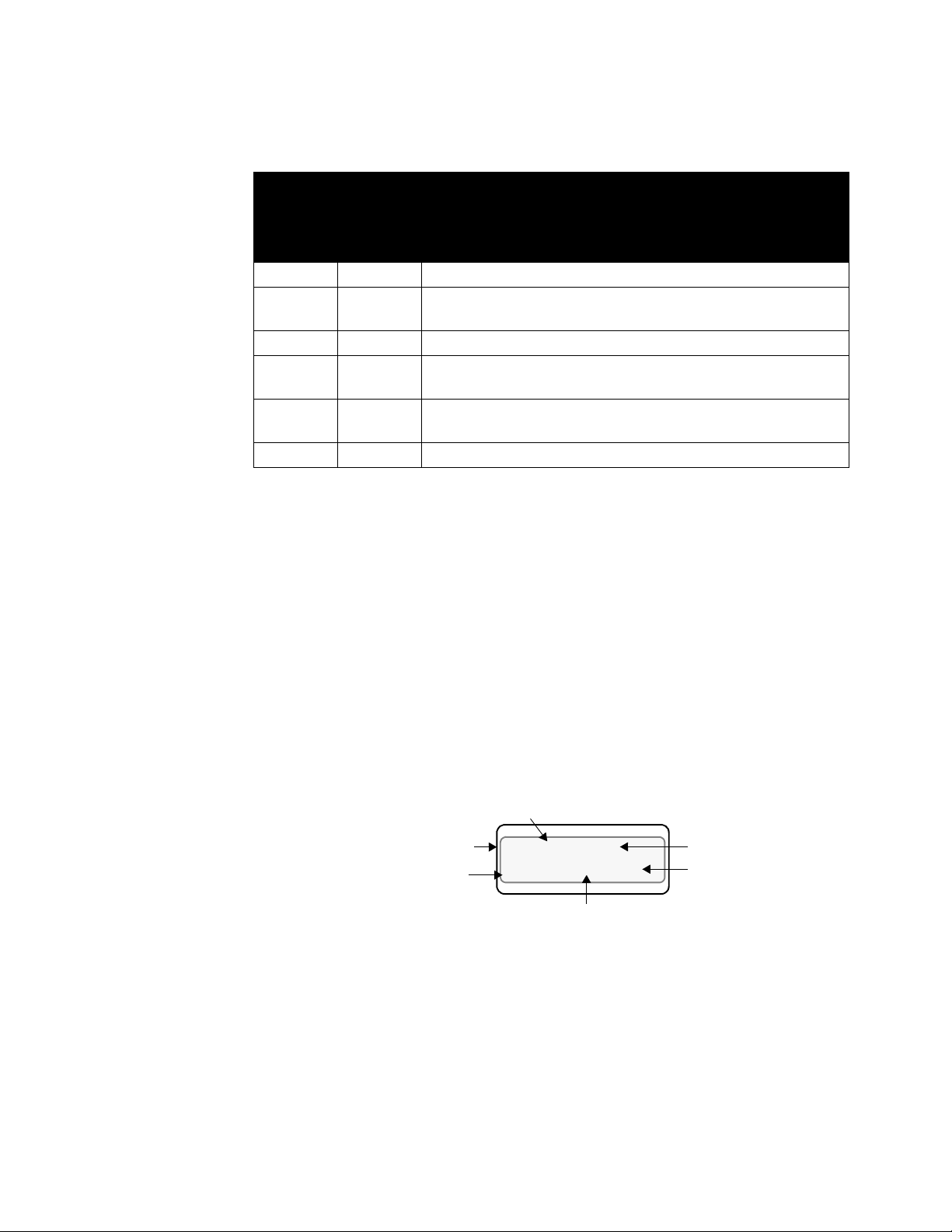
Using the MLS
Bar Graph
DisplaySy
mbol
Single
Loop
DisplaySy
mbol
Description
M MAN One or both outputs enabled. Loop is in manual control.
A AUTO Only one output (Heat or Cool) is enabled. Loop is in automatic
control.
T TUNE Indication th at the loop is in Autotune mode.
H
T
C
L
(blank) (blank)
HEAT
COOL
Both heat and cool outputs are enabled. Loop is in Automatic
control and heating.
Both heat and cool outputs are enabled. Loop is in Automatic
control and cooling.
Both outputs disabled, or input type is set to SKIP.
Navigating in Bar Graph Display
Press the Yes (up) or No (down) key to see a new group.
•
Press Enter twice to scan al l gr oups. The g roups will disp lay s equen -
tially for three seconds each. This is called Scanning Mode.
•
Press Back, Yes or No to go back to Bar Graph display.
•
From Bar Graph display, press Back once to go to Single Loop dis-
play.
Viewing One Loop: Single Loop Display
Single Loop display (below) shows detailed information for only one
loop. If the heat and co ol o utput s ar e enabled, Single Loop di s pla y lo oks
like this:
Process Variable
Loop Number
or Name
Setpoint
The control status indicator shows HEAT or COOL if the loop is in
automatic control, and MAN or TUNE if the loop is in manual control.
LOOP PROCESS UNITS
02 160
º
F
180 AUTO 100
ALARM SETPOINT STATUS OUT%
Control Status
Engineering
Units
Output
percentage
52 MLS User’s Guide
Page 65

Using the MLS
If only one output is enabled (heat or cool, but not both), Single Loop
display looks like this:
Interpreting Alarm Display
Engineering Units
º
F 0
Output Percentage
Cool
Output Percentage
Heat
Loop Number
or Name
Setpoint
Process Variable
LOOP PROCESS UNITS
02 160
180 AUTO 100
ALARM SETPOINT STATUS OUT%
Control Status
Navigating in Single Loop Display
From the single loop display,
•
Press the Back key once to get back to Bar Graph display.
•
Press Enter twice to get to the Single Loop Scanning display. (The
Single Loop Scanning display shows information for each loop in
sequence. Data for each loop displays for one second.)
•
Press Back, Yes, or No to return to the Single Loop display.
If an alarm occurs, the alarm interrupts any other display and switches
to the alarm display, as shown in the next figure. If the MLS is in Bar
Graph display, it switches to Bar Graph Alarm display. If it is in Single
Loop display, it switches to Single Loop Alarm display.
Loop Number
or Name
Alarm Symbols Loop Status
Process Variable
Loop number
or Name
Alarm Symbols
LOOP PROCESS UNITS
01 08
AAAA MAMA
ALARM SETPOINT STATUS OUT%
LOOP PROCESS UNITS
02 180
º
F
LP 180 AUTO 0
ALARM SETPOINT STATUS OUT%
Setpoint
Engineering Units
Output Percentage
MLS User’s Guide 53
Page 66

Using the MLS
This table shows the symbols used in each form of the alarm display.
Bar Graph
Symbol
> HP High Process Alarm
> HD High Deviation Alarm
< LP Low Process Alarm
< LD Low Deviation Alarm
B T/C Break Open Input Error
S
O
Aim Comm
Failure
Single Loop
Symbol
RTD Short
RTD Open
Aim Fail MLS-AIM
Description
RTD Short Alarm
RTD Open Alarm
Communications Failure
Acknowledging an Alarm
Press Alarm Ack to acknowledge the alarm. If there are other loops
with alarm conditions, the Alarm display s witches to the next loop in
alarm. Acknowledge all alarms to clear the global alarm digital output
(The keyboard and display won't work for anything else until you
acknowledge each alarm). The alarm symbols are displayed as long as
the alarm condition is valid.
54 MLS User’s Guide
Page 67

Displaying, Loading, and Saving Jobs
LOOP PROCESS UNITS
ALARM SETPOINT STATUS OUT%
LOOP PROCESS UNITS
ALARM SETPOINT STATUS OUT%
LOOP PROCESS UNITS
ALARM SETPOINT STATUS OUT%
Job display appears only if:
•
Y ou have turned on t he Remote Job Sel ect function. (This functi on is
explained in
•
You have selected a job from the job load menu.
When you load a job, Job display shows you the following screen:
JOB 3 RUNNING
If you remotely loaded the job, Job display looks like this:
Chapter 4: Setup
Using the MLS
.)
JOB 3 RUNNING
REMOTELY LOADED
If you modify a job's parameters while the job is running, you 'll see thi s
job message:
JOB 3 RUNNING
DATA MODIFIED
If an alarm occurs, the controller switches to Single Loop Display.
MLS User’s Guide 55
Page 68

Using the MLS
LOOP PROCESS UNITS
ALARM SETPOINT STATUS OUT%
Operator Menus
Changing the Setpoint
You can perform these tasks from Single Loop Display.
Chng SP
Press
01 SETPOINT ?
25
from the loop you want to change. this display appears:
•
•
•
•
Yes
Press
Press
Press
Press No or
the new setpoint.
to change the setpoint.
Yes
or No to change the setpoint value.
Enter
to save your changes and return to Single Loop Display.
Back
to return to Single Loop Display without saving
Selecting Manual, Automatic, or Tune Control
Man/Auto
Press
•
If you set the output mode to
the process according to the configuration information you give it.
•
If you set the output mode to
level.
•
If you set the output mode to
.
If the Loop is in Manual Mode
•
•
•
•
Yes
Press
Press No to skip the mode change menu and set the output level. (See
the
Press
new mode setting.
Press
to toggle the mode.
Manual Output Levels
Back
to return to the single loop display w ithout saving the
Enter
to save your changes and return to single loop display.
Auto
, the MLS automatically controls
Manual
Tune
section for instructions.)
, you need to set the output
, you can tune the PID parameters.
56 MLS User’s Guide
If the loop is in Automatic Mode
•
•
•
Yes
Press
Press
changes.
Press
Mode, set the output level. (To learn how to set the output level, see
Manual Output Levels
to toggle the mode.
Back
Enter
No
or
to return to single loop display without saving your
to save your changes and if you have selected Manual
.)
Page 69

Using the MLS
LOOP PROCESS UNITS
ALARM SETPOINT STATUS OUT%
LOOP PROCESS UNITS
ALARM SETPOINT STATUS OUT%
•
Press Enter, then Back to store the new mode and return to Single
Loop Display without setting an output level.
NOTE
If the loop outputs are disabled, you cannot toggle
between Manual and Automatic output control. If
you try it, the screen shows an error message telling you that the outputs are disabled, as shown
below.
Use the menus in the Setup Loop Outputs main
menu to enable the outputs. (See Chapter 4: Setup
for more information about the Setup menus.)
MAN/AUTO CONTROL
OUTPUTS DISABLED
Setting the Manual Output Levels
You'll only see this menu if you set the current loop to Manual control.
Use this menu to set the manual heat and cool output levels. (The cool
output level menu will only be presen t if the cool output for th e current
loop is enabled; see Outputs Enabled/Disabled in Chapter 4: Setup).
You sh ould see a display like this:
01 SET HEAT
OUTPUT ? 90%
•
Press Yes to change the output power level. (If the MLS' heat outputs
are enabled, you will be able to change the heat output power level.
If only the cool outputs are enabled, you will be able to change only
the cool output power level.)
•
Then press Yes or No to select a new output power level.
•
When you are satisfied with the power level you have chosen, press
Enter to store your changes.
•
Then press No to advance to the cool output menu (if the cool out-
puts on the MLS are enabled).
•
Press Back at any time to discard your changes and return to single
loop display.
MLS User’s Guide 57
Page 70

Using the MLS
Automatically Tuning a Loop
When you use the Autotune function, the contro ller automatically sets
the loop to Manual control, 100% output. (If you selected a continuous
output limit, the controller sets the loop to the output limit.) The
autotune function calculates the appropriate PID constants for the loop
and puts the loop in automatic control with the calculated PID values.
The Autotune function will abort if:
•
The process variable goes over 75% of t he setp oi nt. (R ememb e r, the
controller is at 100% output or at the output limit you set.)
•
The controller has not cal culated PI D constant s after 10 minutes (d ue
to heater failure, sensor failure, etc.).
If the autotune function aborts, it puts the loop into its previous contro l
state (Automatic or Manual control) at the previous output percentages.
To automatically tune a loop, follow these steps:
1. Make sure the process is cold (or stable and well below setpoint).
2. Initiate Autotune:
1. Use the front panel keypad to go to Single Loop Display.
2. Press the Man/Auto key.
3. Choose Tune.
4. Press Enter.
The Tune indicator will flash and the controller will return to Single
Loop Display. The Tune indicator will flash as long as the loop is
tuning.
58 MLS User’s Guide
Page 71
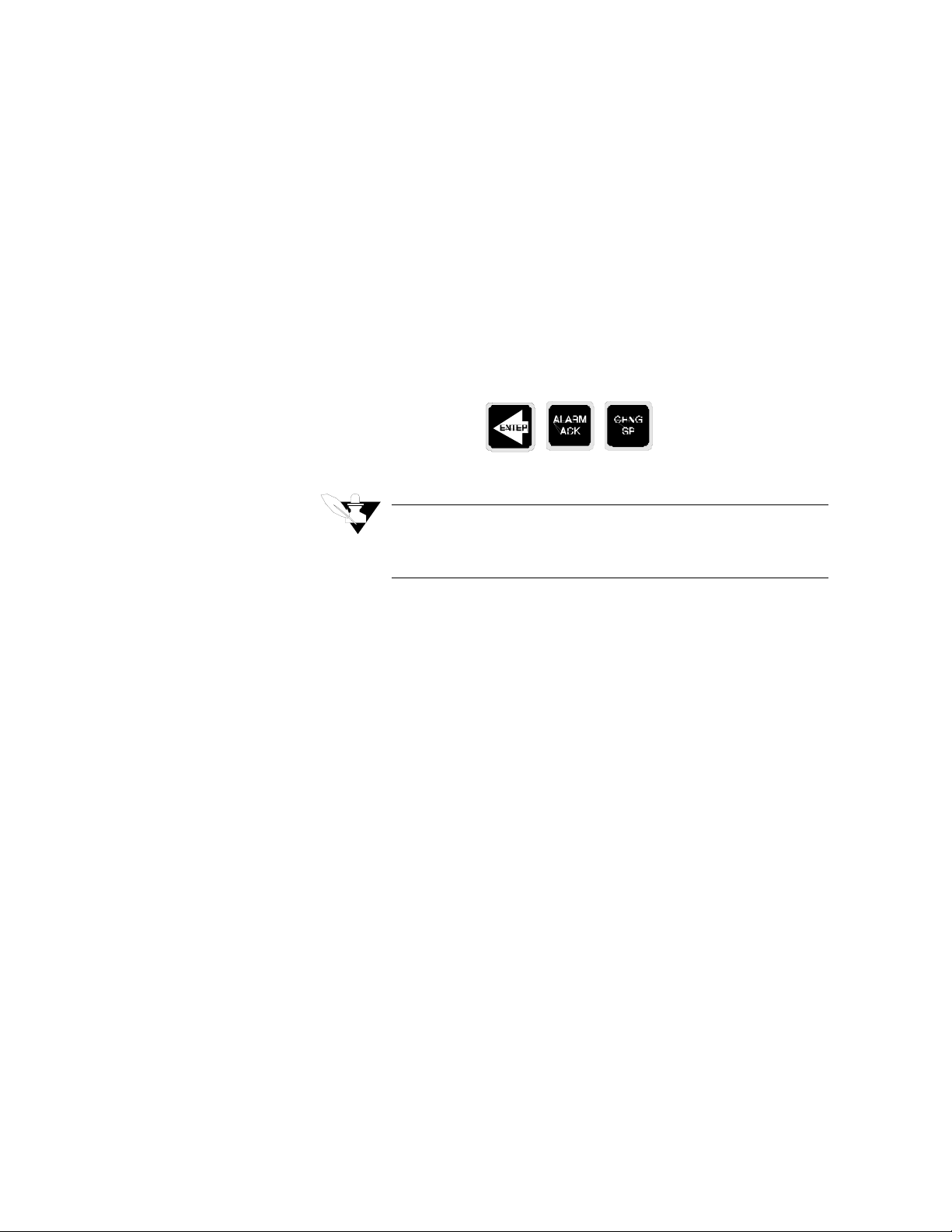
Setup
The Setup menus let you change the MLS' detailed configuration
information.
If you have not set up a Modular Loop System before, or if you don't
know what values to enter , please read first the ne xt chapter,
Control
How to enter the Setup menus?
1. In Single Loop Display, select the loop you wish to edit.
2. While still in Single Loop Display, enter the pass sequence below:
which contains PID tuning constants and useful starting values.
Press
Enter, Alarm Ack, Change Setpoint
.
Tuning and
How to edit a menu?
3. The first setup menu appears.
NOTE
For your protection, MLS reverts to Single Loop Display If you don't make any changes for three minutes.
•
Press
Yes
to select this menu or No to advance to the next menu.
•
press
Yes
or No to toggle between the options in your menu.
•
Press Enter to store the value you have selected.
If you decide not to edit the menu, press Back to stop editing and
•
return to the main menu.
In the next sections you will find detailed information about the
submenus for each of the six main menus.
Each display contains the default value for that specific menu, and
below each display you will see the range of choices for that menu.
The next page shows a diagram describing the six main menus and all
the submenus in each one of them.
MLS User’s Guide 59
Page 72
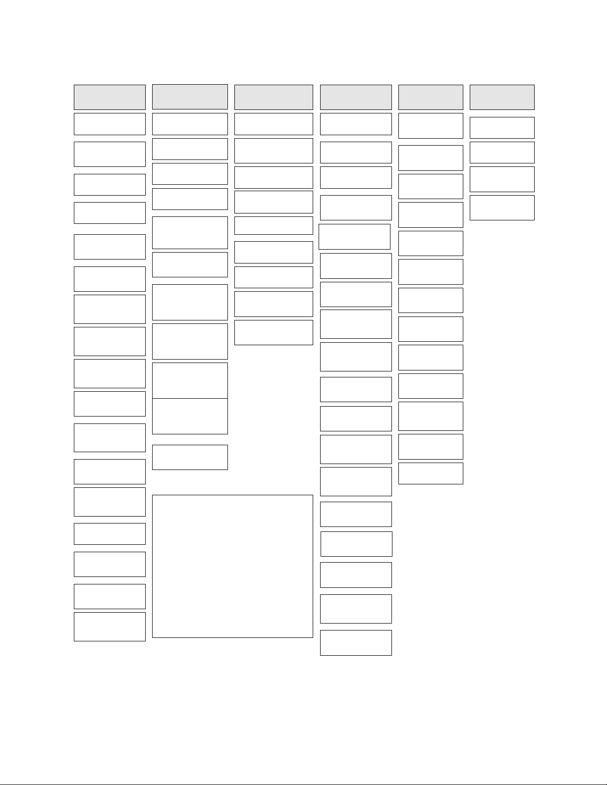
Setup
Setup Global
Parameters?
save setup to
job?
Load setup from
job?
Job control
dig inputs?
Job digital input
true?
Output override
dig input?
Override dig
in active?
Startup alarm
delay?
Keyboard lock
status?
Power up output
status?
Controller
address?
Communications
err check?
Communications
baud rate?
Allen Bradley
protocol?
AC line freq?
Digout outputs
active?
AIM comm.
failure output?
EPROM
information
Setup Loop xx
Input?
Input type?
Pulse sample time?
Loop name?
Input units?
Input reading
offset (T/C &
RTD)?
Disp format
(Linear & Pulse)?
Input scaling
Hi pv? (Linear &
Pulse)
Input scaling
Hi rdg? (Linear &
Pulse)
Input scaling
Lo pv? (Linear &
Pulse)
Input scaling
Lo RDG? (Linear
& Pulse)
Lo pass filter
value?
Setup Loop xx Setup loop xx
Control Params?
Heat control PB?
Heat control TI?
Heat control TD?
Heat control filter?
Cool control PB?
Cool control TI?
Cool control TD?
Cool control filter?
Heat/Cool
spread?
Press Enter, Alarm Ack, Change
Setpoint to reach these menus.
Press Yes to use a menu.
Press Up or Down to change a
value or select an option.
Press Enter to store the value you
have changed.
Press Back to escape a menu
without changing it.
Outputs?
Heat control out?
Heat output
type?
Heat output
cycle time? (TP)
SDAC menus
(SDAC)
Heat output
action?
Heat output
limit?
Heat output
limit time?
Sensor fail
Ht output?
Outputs heat
NLO?
Cool control out?
Cool output
type?
Cool output
cycle time?
SDAC menus
(SDAC)
Cool output
action?
Cool output
limit?
Cool output
limit time?
Sensor fail
Cl output?
Outputs cool
NLO?
Setup Loop
xx Alarms?
High process
alarm setpoint?
High process
alarm type?
High process
alarm dig out?
Deviation
alarm value?
High deviation
alarm type?
Alarm dig out?
Low deviation
alarm type?
Low deviation
alarm dig out?
Low process
alarm setpoint?
Low process
alarm type?
Low process
alarm dig out?
Alarm deadband?
Alarm delay?
Manual I/O
Test?
Digital inputs?
Keypad test?
Test digital
output?
Digital output
number?
60 MLS User’s Guide
Page 73

Setup Global Parameters Menu
The setup global parameters menu looks like this
LOOP PROCESS UNITS
Below is the setup global parameters menu tree. Notice the default
values inside the boxes.:
Setup
SETUP GLOBAL
PARAMETERS?
ALARM SETPOINT STATUS OUT%
Setup Global Parameters?
Save setup to job? 1
Load setup from job? 1
Job control digital inputs?
NONE
Job digital input true?
LOW
Output override dig
input? NONE
Override dig in active?
LOW
Startup alarm delay?
0 MINS
Keyboard lock status?
OFF
Power up output status?
OFF
Controller address? 1
Communications err
check? BCC
Communications baud
rate? 9600
Allen Bradley protocol?
NO
AC line freq.?
60 HERTZ
Digout outputs active?
LOW
AIM communications
failure output? NONE
EPROM information
MLS User’s Guide 61
Page 74

Setup
Save to Job
Use this menu to save the job information for every loop to one of eight
jobs in the MLS’ battery-backed RAM.
LOOP PROCESS UNITS
SAVE SETUP
TO JOB? 1
ALARM SETPOINT STATUS OUT%
Selectable Range: 1-8.
If you have enabled the remote job control function, you will not be able
to save a job; when you try to do it, you will see this message:
LOOP PROCESS UNITS
CANNOT SAVE JOB
REMOTE SELECT
ALARM SETPOINT STATUS OUT%
Load from Job
Use this menu to load any one of eight saved jobs from the controller’s
front panel.
LOOP PROCESS UNITS
LOAD SETUP
FROM JOB? 1
ALARM SETPOINT STATUS OUT%
Selectable values: The last job number or job 1.
The following parameters are loaded as part of a job:
1. PID constants, filter settings, setpoints, and spread values.
2. Loop control status (Automatic or Manual), and output values (If the
loop is in Manual control).
3. Alarm functions (Off, Alarm, Control), setpoints, high/low process
setpoints, high/low deviation setpoints and deadband settings, and
loop alarm delay.
If you have enabled the remote job control function, this menu is
disabled .
62 MLS User’s Guide
Page 75

Job Select Inputs
Setup
Use the Remote Job Control feature to run up to 8 jobs remotely. The
Job Select Inputs menu is the third menu under Setup Global
Parameters. It lets you set the number of job select inputs. The controller
uses these inputs as a binary code that specifies the job number to run.
The number of inputs you choose in this menu controls the number of
jobs you can select remotely. The menu looks like this:
LOOP PROCESS UNITS
JOB CONTROL DIG
INPUTS? NONE
ALARM SETPOINT STATUS OUT%
Selectable values: 1, 2, 3 , or NONE.
Below is the truth table that tells you which input states select which
jobs.
Digital
Input 3
FF F 1
FF T 2
FT F 3
FT T 4
TF F 5
TF T 6
TT F 7
TT T 8
Digital Input 2 Digital Input
1
Job #
You can choose 1, 2, or 3 inputs, or None. These choices have the
following effect:
Setting Enables
1 input Jobs 1-2
2 inputs Jobs 1-4
3 inputs Jobs 1-8
None (no inputs) Remote Select disabled
MLS User’s Guide 63
Page 76

Setup
Job Digital Input Polarity
Output Override Digital Input
Use this menu to set the polarity of the digital outputs used for job
selection. You can set the Active state to closed (Low) or open (High).
LOOP PROCESS UNITS
JOB DIGITAL INPUT
TRUE? LOW
ALARM SETPOINT STATUS OUT%
Selectable values: Low or High.
This menu lets you set a digital input that sets all loops in manual
output at output levels you select in the Outputs menu. This menu, and
the next one, let you configure a "panic button" or "kill switch" that sets
all outputs to the output override percentage you set in the Setup Loop
Outputs main menu.
OUTPUT OVERRIDE
DIG INPUT? NONE
Selectable values: Input number 1-8, or NONE.
WARNING
ANAFAZE recommends that you install additional
external safety devices or over-temperature
devices for emergency shutdowns. Do not rely
solely on the output override feature to shut down
your process.
Output Override Input Polarity
This menu lets you toggle the polarity of the Output Override digital
input. You can set the input to be active when Low or active when High.
LOOP PROCESS UNITS
OVERRIDE DIG IN
ACTIVE? LOW
LOOP PROCESS UNITS
ALARM SETPOINT STATUS OUT%
ALARM SETPOINT STATUS OUT%
64 MLS User’s Guide
Selectable values: Low or High.
Page 77

Startup Alarm Delay
Keyboard Lock Status
Setup
Use this menu to set a startup delay for process and deviation alarms for
all loops. The controller does not report these alarm conditions for the
specified number of minutes after the controller powers up. (The
controller will always report failed sensor alarms, no matter what startup
delay you set.)
LOOP PROCESS UNITS
ST AR TUP ALARM
DELAY? 0 mins
ALARM SETPOINT STATUS OUT%
Selectable Range: 0-60 minutes.
Power-Up Output Status
Use this menu to lock the front panel operator function keys Change SP,
Man/Auto, and Ramp/Soak so that pressing these keys has no effect. If
you want to use these functions, turn off the Keyboard Lock.
LOOP PROCESS UNITS
KEYBOARD LOCK
STATUS? OFF
ALARM SETPOINT STATUS OUT%
Selectable values: On or Off.
Use this menu to set the initial power-up state of the control outputs to
Off or Memory. If you choose Off, all control outputs are initially set to
Manual mode at 0% output level. If you choose Memory, the outputs are
restored to the last output state stored in memory.
LOOP PROCESS UNITS
POWER UP OUTPUT
STATUS? OFF
ALARM SETPOINT STATUS OUT%
Selectable values: Off or Memory.
WARNING
Do not set the MLS to start from memory if a
memory-based restart is unsafe for your process.
MLS User’s Guide 65
Page 78

Setup
Controller Address
Communications Error Checking
Use this menu to set the MLS controller address. The controller address
is used for multiple controller communications on a single RS-485
cable, so each MLS must have a different address. Begin with address 1
for the first controller and assign each subsequent controller the next
higher address.
LOOP PROCESS UNITS
CONTROLLER
ADDRESS? 1
ALARM SETPOINT STATUS OUT%
Selectable Range: a number between 1 and 32.
Use this menu to set the data check algorithm used in the ANAFAZE
communications protocol to Block Check Character (BCC) or to Cyclic
Redundancy Check (CRC).
CRC is a more secure error checking algorithm than BCC, but it
requires more calculation time and slows the MLS communications.
BCC ensures a high degree of communications integrity, so ANAFAZE
recommends that you use BCC unless your application specifically
requires CRC.
LOOP PROCESS UNITS
COMMUNICATIONS
ERR CHECK? BCC
ALARM SETPOINT STATUS OUT%
Selectable values: BCC or CRC.
NOTE
If you are using ANASOFT, be sure to configure
ANAINSTL for the same error checking method that
you set in this menu.
66 MLS User’s Guide
Page 79

Communications Baud Rate
Setup
Use this menu to set the Communications Baud Rate to 2400 or 9600
baud.
LOOP PROCESS UNITS
COMMUNICATIONS
BAUD RATE? 9600
ALARM SETPOINT STATUS OUT%
Selectable values: 9600 or 2400.
NOTE
If you use ANASOFT, be sure to set ANAINSTL to
the same baud rate that you set in this menu.
Allen Bradley Protocol
AC Line Frequency
Use this menu to set the protocol type to either Allen Bradley or
ANAFAZE.
LOOP PROCESS UNITS
ALLEN BRADLEY
PROTOCOL? NO
ALARM SETPOINT STATUS OUT%
Selectable values: Yes or No.
Use this menu to configure the controller to match an AC line frequency
of 50 or 60 Hz. (This function is provided for international users who
require 50 Hz lines.) Since the controller reduces the effect of power
line noise on the analog measurement by integrating the signal over the
period of the AC line frequency, the controller's noise rejection will
suffer if the line frequency is not set correctly.
LOOP PROCESS UNITS
AC LINE FREQ ?
60 HERTZ
ALARM SETPOINT STATUS OUT%
Selectable values: 60 Hz or 50 Hz.
NOTE
If you change the AC line frequency, you must switch
power to the MLS on and off for the change to take
effect.
MLS User’s Guide 67
Page 80

Setup
Digital Output Polarity
AIM Communications Failure Output
Use this menu to set the polarity of the digital outputs used for alarms.
The output can be active High or active Low.
LOOP PROCESS UNITS
DIGOUT OUTPUTS
ACTIVE? LOW
ALARM SETPOINT STATUS OUT%
Selectable values: High or Low.
Use this menu to select the digital output that activates if
communications fail between the MLS-AIM and the MLS-PM. You can
use this output, along with the Global Alarm output, to power an alarm
horn or buzzer that sounds if communications fail between the AIM and
the PM.
EPROM Information
The global alarm will activate if there is an AIM communications
failure, and will reset automatically when the problem is corrected. The
controller will revert to manual mode during an AIM communications
failure.
LOOP PROCESS UNITS
AIM COMM FAILURE
OUTPUT? NONE
ALARM SETPOINT STATUS OUT%
Selectable values: any output from 1 to 34 as long as it’s not used for
control or for SDAC clock, or NONE.
Use this last menu of the Setup Global Parameters main menu to see the
controller's EPROM version and checksum.
LOOP PROCESS UNITS
MLS
VO 2.60
ALARM SETPOINT STATUS OUT%
Press any key from this menu to return to the Setup Parameters menu.
68 MLS User’s Guide
Page 81
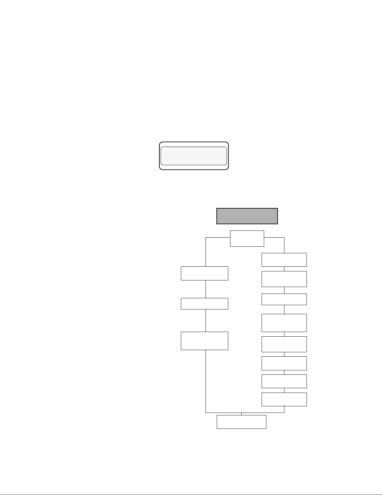
Setup Loop Input
Setup
The Setup Loop Input main menu lets you access menus which change
loop input parameters:
•
Input type
•
Input scaling and calibration
Input filtering
•
The next section explains how to configure inputs via the front panel.
LOOP PROCESS UNITS
SETUP LOOP 02
INPUT?
ALARM SETPOINT STATUS OUT%
Below is the menu tree for the Setup Loop Inputs menu. Notice the
default values inside the boxes.
Setup Loop Inputs?
Linear & PulseT/C or RTD
pulse sample
time?
Loop’s name?
Input units? __
Disp format?
-9999 to 30000
Input scaling
Hi PV? 10000
Input scaling Hi
RDG? 100.0% FS
Loop’s name?
Input units?
Input reading
offset? 0
ºF
ºF
Input T ype?
J T/C
Low pass filter
value? 3
input scaling
Lo PV? -1660
Input scaling Lo
RDG? -16.6%FS
MLS User’s Guide 69
Page 82
Setup
Input Type
Use this menu to configure the input sensor for each loop as one of these
input types:
Thermocouple types (J, K, T, S, R and B).
•
RTD. Three ranges: RTD1 (Platinum Class A), RTD2 (Platinum
•
Class B), and RTD3 (Nickel).
•
Linear and Pulse inputs.
•
Skip (an input type available for unused channels.) The scanning dis-
play doesn't show loops you've set to Skip.
LOOP PROCESS UNITS
06 INPUT TYPE?
J T/C
ALARM SETPOINT STATUS OUT%
The next table shows the MLS' input types and ranges.
Input
Type
J -350 to +1400 -212 to +760
K -450 to +2500 -268 to +1371
T -450 to +750 -268 to +399
S 0 to +3200 -18 to +1760
R 0 to +3210 -18 to +1766
B +150 to +3200 +66 to +1760
RTD1 -148.0 to +572.0 -100.0 to +300.0
RTD2 -184 to +1544 -120 to +840
RTD3 -94 to 572 -70 to 300
Pulse 0-2 KHz
Skip Loop is not scanned or displayed.
Linear see the
Fahrenheit
Range
Linear Scaling section
ter) and
Celsius Range
(this chap-
Appendix
.
70 MLS User’s Guide
Page 83
Pulse Sample Time
Setup
You can connect a digital pulse signal of up to 2 KHz to the controller’s
pulse input. Use this menu to specify the pulse sample period. Every
sample period, the number of pulses the controller receives is divided by
the sample time. The controller scales this number and uses it as the
pulse loop’s PV.
LOOP PROCESS UNITS
06 INPUT PULSE
SAMPLE TIME? 1s
ALARM SETPOINT STATUS OUT%
Selectable range: 1-20 seconds .
Loop Name
Input Units
Use this menu to name your loop. You can choose any two characters
from the set of characters used for the input units.( See table below).
LOOP PROCESS UNITS
A5 LOOP SAMPLE NAME? A5
ALARM SETPOINT STATUS OUT%
Use this menu to choose a three-character description of the loop's
engineering units.
LOOP PROCESS UNITS
06 INPUT
UNITS? º F
ALARM SETPOINT STATUS OUT%
Selectable values:
This table shows the character set for input units.
Input Character Sets for Units
thermocouples & RTDs F or C degrees
Linear and Pulse 0-9, A-Z, %, degrees, /, space
MLS User’s Guide 71
Page 84

Setup
Input Reading Offset
Use this menu to make up for the input signal's inaccuracy. For
example, at temperatures below 400 ºF, a type J thermocouple may be
inaccurate ("offset") by several degrees F. Use an independent
thermocouple or your own calibration equipment to find the offset for
your equipment. To correct for offset errors, change the factory default
setting to a positive or negative value for the loop you are editing. (A
positive value increases the reading and a negative value decreases it.)
LOOP PROCESS UNITS
06 INPUT READING
OFFSET? 0 º F
ALARM SETPOINT STATUS OUT%
Linear Scaling Menus
Selectable range:
-300 to +300.
NOTE
If the input type is Linear, Pulse, or Skip, you will not
see the Input Reading Offset menu.
The linear scaling menus appear under the Setup Loop Inputs main
menu, and they are available for Linear and Pulse inputs only. It lets you
scale the "raw" input readings (readings in millivolts or hertz) to the
engineering units of the process variable.
You'll only see the linear scaling menus if you set the
loop's input type to Linear or Pulse.
For linear inputs, the input reading is in percent (-16.6 to 100%)
representing the -10-60 mV input range of the MLS. The scaling
function is defined by two points on a conversion line. It relates the high
PV to the high reading and the low PV to the low reading to define the
line. The engineering units of the process variable can be any arbitrary
units.
72 MLS User’s Guide
Page 85

Setup
The graph below shows pressure as an example.
Before you enter the values that determine the two points for the
conversion line, you must choose an appropriate display format. The
MLS has six characters available for process variable display; select the
setting with the desired number of decimal places before and after the
decimal point. Use a display format that matches the range and
resolution of the process variable. The display format you choose is
used for the setpoint, alarms, deadband, spread, and proportional band.
Hi PV
Proces s
Varia ble
Range
Lo PV
The PV (Process Variable) range for the scaled input is between the PV
values that correspond to the -16.6% and 100% input readings. This PV
range defines the limits for the setpoint and alarms, as shown here.
0PSI
0%
0mV
0Hz
Lo
RDG
Input Reading
Hi
RDG
100%
}Line a r input type
60 mV
} Pulse input type
2000 Hz
NOTE
See Linear Scaling Examples section in this manual.
MLS User’s Guide 73
Page 86
Setup
Display Format
Use this menu to select a display format for a linear input. Choose a
format appropriate for your input range and accuracy.
LOOP PROCESS UNITS
05 DISP FORMAT
-9999 TO 30000
ALARM SETPOINT STATUS OUT%
Selectable values: The MLS has several available display formats, as
shown below. this table shows also the high and low PV values. .
Display Formats High PV Default Low PV Default
-9999 to +30000 10000 0
-999 to +3000 1000 0
-99 to +300 100 0
-9 to +30 10 0
-.9999 to +3.0000 1.0000 .0000
-9.999 to +30.000 10.000 .000
-99.99 to +300.00 100.00 .00
-999.9 to +3000.0 1000.0 .0
High Process Value
Use this menu to enter a high process value. The high process value and
the high reading value together define one of the points on the linear
scaling function's conversion line.
LOOP PROCESS UNITS
01 INPUT SCALING
HI PV? 10000 º F
ALARM SETPOINT STATUS OUT%
Selectable values: See table above.
74 MLS User’s Guide
Page 87

High Reading
Low Process Value
Setup
Use this menu to enter the input level that corresponds to the high
process value you entered in the previous menu. For linear inputs, the
high reading is a percentage of the full scale input range. For pulse
inputs, the high reading is expressed in Hz.
The 100% full scale input value is 60 mV for the linear input type.
LOOP PROCESS UNITS
09 INPUT SCALING
HI RDG = 100.0% FS
ALARM SETPOINT STATUS OUT%
Selectable range: Any value between -99.9 and 110.0. For pulse input,
the range is 0-2000 Hz, and the default is 1000 Hz.
Low Reading
Use this menu to set a low process value for input scaling purposes. The
low process value and the low reading value together define one of the
points on the linear scaling function's conversion line.
LOOP PROCESS UNITS
02 INPUT SCALING
LO PV? 0 º F
ALARM SETPOINT STATUS OUT%
Selectable values: See table on previous page.
Use this menu to enter the input level that corresponds to the low
process value you selected in the previous menu. For linear inputs, the
low reading is a percentage of the full scale input range. For pulse
inputs, the low reading is expressed in Hz.
LOOP PROCESS UNITS
12 INPUT SCALING
LO RDG ? .-16.6%FS
ALARM SETPOINT STATUS OUT%
The full scale input range for the linear input type is -10 to 60 mV,
which corresponds to -16.6 to 100.0%.
Selectable range: Any value between - 99.9 and 110.0. For pulse
inputs, the range is 0-2000 Hz, and the default is 0.
MLS User’s Guide 75
Page 88

Setup
Input Filter
Access this menu from the Setup Loop Inputs main menu. The MLS has
two different types of input filter:
• A noise rejection filter that rejects high frequency input signal noise.
This filter keeps a "trend log" of input readings. If a reading is outside the filter's "acceptance band", and later readings are within the
acceptance band, the MLS ignores the anomalous reading. (The
acceptance band for thermocouples is 5 degrees above and 5
degrees below the input reading. For linear inputs, it's 0.5% above
and 0.5% below the input reading.) If later readings are also outside
the acceptance band, the MLS accepts the anomalous reading and
calculates a new acceptance band. (This input filter does not require
adjustment.)
• A standard resistor-capacitor (RC) filter that lets you dampen the
input response if inputs change unrealistically or change faster than
the system can respond. If the input filter is enabled, the process
variable responds to a step change by going to 2/3 of the actual
value within the number of scans you set.
If all input loops are enabled (none of them are set to SKIP) the MLS
scans each input loop 2 times per second. The input filter applies to all
input types except those set to SKIP.
LOOP PROCESS UNITS
01 LOW PASS FILTER
VALUE? 3 SCANS
ALARM SETPOINT STATUS OUT%
Selectable range: 0-255 scans.
76 MLS User’s Guide
Page 89
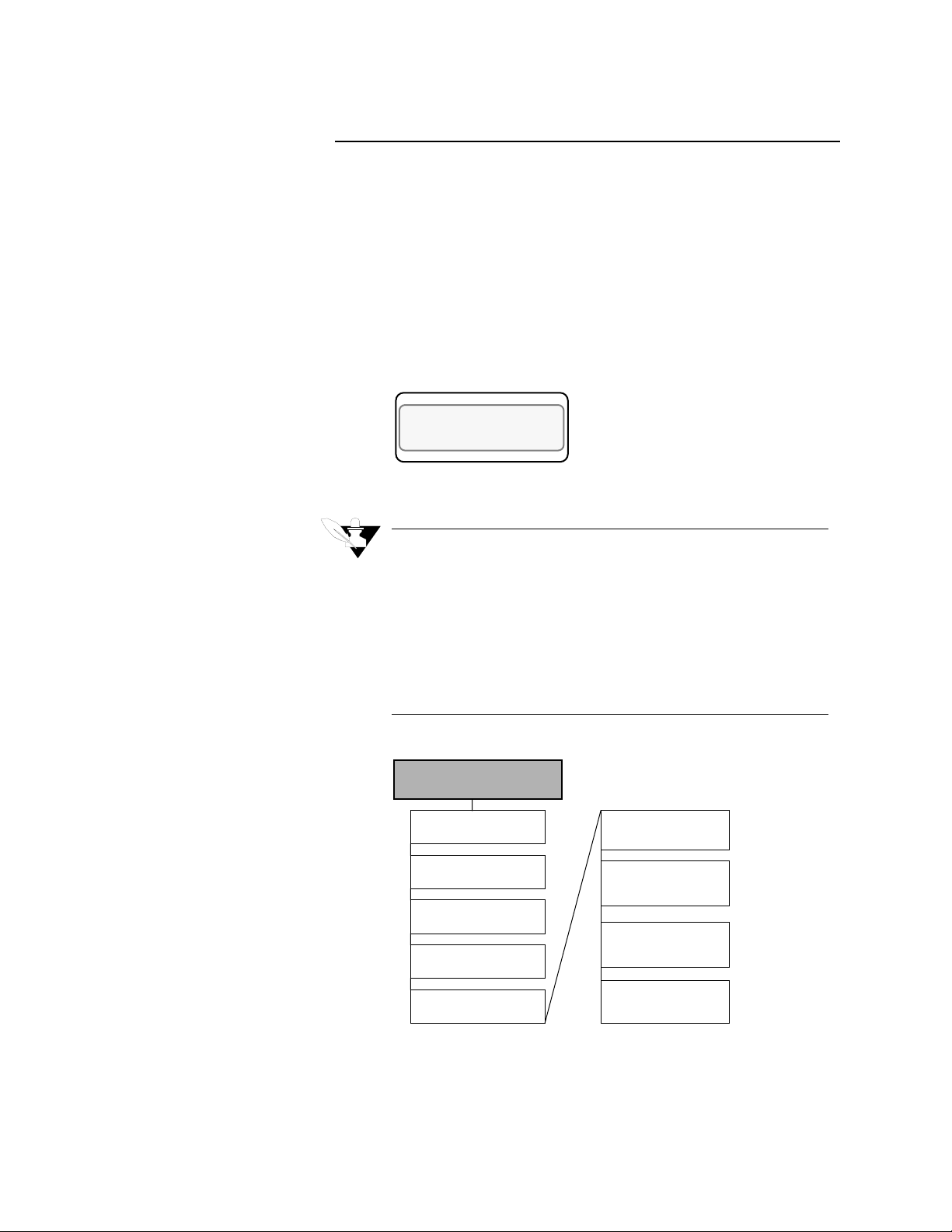
Setup Loop Control Parameters
Use these menus to change control parameters for heat and cool outputs
of the selected loop, including:
• Proportional Band (PB), Integral (TI or Reset), and Derivative (TD
or Rate) settings.
• Output Filter.
• Spread between heat and cool outputs.
The Setup Loop Control Parameters menu looks like this:
LOOP PROCESS UNITS
SETUP LOOP 01
CONTROL PARAMS?
ALARM SETPOINT STATUS OUT%
Setup
NOTE
Both heat and cool outputs have the same menus, so
only one of each menu is explained in the text. The
controller shows both heat and cool menus even if the
heat or cool output is disabled. (See Setup Loop Out-
puts for help in enabling or disabling the heat or cool
output.)
Refer to Tuning and Control section for help in
selecting control parameter values.
Setup Loop Control
Parameters?
Heat control PB?
50
ºF
Heat control TI?
60 Sec/R
Heat control TD?
0 Sec.
Heat control filter?
2
Cool control PB?
ºF
50
Cool control TI?
60 Sec/R
Cool control TD?
0 Sec.
Cool control filter?
2
Heat / Cool
spread? 5
ºF
MLS User’s Guide 77
Page 90

Setup
Heat/Cool Control PB
Use this menu to set the Proportional Band.
LOOP PROCESS UNITS
01 HEAT CONTROL
PB? 50 ºF
ALARM SETPOINT STATUS OUT%
NOTE
The MLS internally represents the proportional band
(PB) as a gain value. When you edit the PB, you'll see
the values change in predefined steps--small steps for
narrow PB values and large steps for wide PB values.
The controller calculates the default PB for each input type according to
the following equation:
Heat/Cool Control TI
Heat/Cool Control TD
Default PB =
(High Range - Low Range)
Gain
Use this menu to set the Integral term, or Reset.
LOOP PROCESS UNITS
01 HEAT CONTROL
TI ? 180 SEC/R
ALARM SETPOINT STATUS OUT%
Selectable range: 0-6000 seconds.
Use this menu to set the derivative constant.
LOOP PROCESS UNITS
15 HEAT CONTROL
TD ? 0 SEC
ALARM SETPOINT STATUS OUT%
78 MLS User’s Guide
Selectable range: 0-255 seconds.
Page 91

Heat/Cool Output Filter
Heat/Cool Spread
Setup
Use this menu to dampen the heat or cool output's response. The output
responds to a step change by going to approximately 2/3 of its final
value within the number of scans you set here.
LOOP PROCESS UNITS
07 HEAT CONTROL
FILTER ? 2
ALARM SETPOINT STATUS OUT%
Selectable range: 0-255. Setting the output filter to 0 turns it off.
Use this menu to set the spread between the heat and cool output and the
spread of the On/Off control action.
LOOP PROCESS UNITS
01 HEAT
SPREAD ? 5 ºF
ALARM SETPOINT STATUS OUT%
Selectable range: The spread ranges from 0 to 255, 25.5, 2.55, .255 or
.0255, depending on the way you set up the input menus.
MLS User’s Guide 79
Page 92

Setup
Setup Loop Outputs
Press Yes at this prompt to access menus to change loop output
parameters for the current loop, including:
• Enable or disable outputs
• Output type
• Cycle time (for TP outputs)
• SDAC parameters (for SDAC outputs)
• Control action
• Output level limit and limit time
• Output override
• Nonlinear output curve
Both heat and cool outputs have the same menus, so only one of each
menu is explained in this section. (The next page shows a menu tree.)
Here's the main menu:
LOOP PROCESS UNITS
SETUP LOOP 03
OUTPUTS ?
ALARM SETPOINT STATUS OUT%
The figure on the next page shows the menu tree for the output setup
menus. Notice the default values inside the boxes
80 MLS User’s Guide
Page 93

Setup Loop Outputs?
Heat/Cool control out?
Output
Enabled
Heat/Cool output type?
Setup
Output disabled
For SDAC outputsFor TP outputs
Heat/cool output
cycle time? 10 S
For ON/OFF DZC
Heat/Cool output action?
Reverse
Heat/Cool output limit?
100%
Sensor fail Heat/Cool
output? 0%
SDAC mode?
Voltage
SDAC Lo value?
0.00
SDAC Hi value?
10.00 VDC
Heat/Cool output limit
time? CONT
Outputs Heat/Cool NLO?
OFF
MLS User’s Guide 81
Page 94

Setup
Enable/Disable Heat and Cool Outputs
Heat or Cool Output Type
Use this menu to enable or disable the heat or cool output for the current
loop. If you want the loop to have PID control, you must enable one
output. You can also disable a heat or cool control output and use the
output pin for something else, like an alarm.
LOOP PROCESS UNITS
05 HEAT CONTROL
OUT? ENABLED
ALARM SETPOINT STATUS OUT%
Selectable values: Enabled or Disabled. The default setting enables the
heat outputs and disables the Cool outputs.
Use this menu to set the output type. .
LOOP PROCESS UNITS
14 HEAT OUTPUT
TYPE = TP
ALARM SETPOINT STATUS OUT%
The next table shows the available output types.
Display
Code
TP Time
DZC Distributed
SDAC Serial DAC Output type for optional Serial Digital-Analog
ON/OFF On / Off Output either full ON of full OFF.
Output
Type
Proportioning
Zero Crossing
Definition
Percent output converted to a percent duty
cycle over the programmed cycle time.
Output on/off state calculated for every AC line
cycle.
Converter (SCAC)
For an expanded description of these output types, see Tuning and
Control.
82 MLS User’s Guide
Page 95

Heat/Cool Cycle Time
Setup
Use this menu to set the Cycle Time for Time Proportioning outputs.
LOOP PROCESS UNITS
03 HEAT OUTPUT
CYCLE TIME ? 10S
ALARM SETPOINT STATUS OUT%
Selectable range: 1-255 seconds.
NOTE
The Cycle Time menu will only be present if the output type for the current loop is Time Proportioning.
SDAC Menus
SDAC Mode
If you attach the optional SDAC to an output, you must configure that
output for the SDAC using the following series of menus. The MLS will
also assign digital output #34 as a clock line for the SDA C. You won't be
able to assign another function to output #34 while any loop's output is
set to SDAC.
Use this menu to toggle the SDAC between current and voltage output.
The SDAC menus only appear if the output type for the loop is set to
SDAC .
LOOP PROCESS UNITS
01 SDAC MODE ?
VOLTAGE
ALARM SETPOINT STATUS OUT%
Selectable values: Current and Voltage.
MLS User’s Guide 83
Page 96

Setup
SDAC High Value
SDAC Low Value
Use this menu to set a high value for the SDAC output. Set the high and
low value to match the range of the output device. For instance, if the
output device has a 4-20 mA range, set the SDAC high value to 20.00
mA and the SDAC low value to 4.00 mA. The controller converts 0%
output to a 4.00 mA signal and 100% output to a 20.00 mA signal.
LOOP PROCESS UNITS
03 SDAC HI VALUE ?
10.00 VDC
ALARM SETPOINT STATUS OUT%
Selectable values: If the output is set to Voltage, the default high value
is 10.00 volts. If the output is set to Current, the default high value is
20.00 mA. You cannot set the high value to be less than or equal to the
low value.
Heat/Cool Output Action
Use this menu to set a low value for the SDAC output. Set the high and
low value to match the range of the output device. For instance, if the
output device has a 0.00-10.00 Vdc range, set the SDAC high value to
10.00 Vdc and the SDAC low value to 0.00 Vdc. The controller converts
0% output to a 0.00 Vdc signal and 100% output to a 10.00 Vdc signal.
LOOP PROCESS UNITS
04 SDAC LO VALUE ?
0.00 VDC
ALARM SETPOINT STATUS OUT%
Selectable values: If the output is set to Voltage, the default low value is
0.00 volts. If the output is set to Current, the default value is 4.00 mA.
You cannot set the low value to be greater than or equal to the high
value.
Use this menu to select the control action for the current output loop.
Normally, heat outputs are set to reverse action and cool outputs are set
to direct action.
LOOP PROCESS UNITS
01 HEAT OUTPUT
ACTION ? REVERSE
ALARM SETPOINT STATUS OUT%
84 MLS User’s Guide
Selectable values: Reverse or Direct.
For Heat outputs, set to Reverse; for Cool outputs, set to Direct.
Page 97

Heat/Cool Output Limit
Use this menu to limit the maximum PID control output for a loop's heat
and cool outputs. This limit may be continuous, or it may be in effect for
a specified number of seconds (see Output Limit Time on the next
page). If you choose a timed limit, the output limit restarts when the
controller powers up and when the output goes from Manual to
Automatic control (via the front panel, when the controller changes
jobs, or from ANASOFT.) The output limit only affects loops under
automatic control. It does not affect loops under manual control.
Selectable range: 0-100%
Heat/Cool Output Limit Time
Setup
LOOP PROCESS UNITS
01 HEAT OUTPUT
LIMIT ? 100%
ALARM SETPOINT STATUS OUT%
Heat/Cool Output Override
Use this menu to set a time limit for the output limit.
LOOP PROCESS UNITS
04 HEAT OUTPUT
LIMIT TIME ? CONT
ALARM SETPOINT STATUS OUT%
Selectable values: 1-999 seconds, or CONT (continuous).
Use this menu to set an output override percentage. (You can configure a
digital input for the output override in the Setup Global Parameters main
menu.) If the current loop is in Automatic mode and a sensor failure
occurs, the loop switches to the output override percentage, manual
mode. If you change the polarity of the override output to the active
state--for instance, by flipping a "kill switch" you have set up--every
loop switches to the output override percentage you set here.
LOOP PROCESS UNITS
03 SENSOR FAIL
HT OUTPUT ? 0%
ALARM SETPOINT STATUS OUT%
Selectable range: 0-100%
MLS User’s Guide 85
Page 98
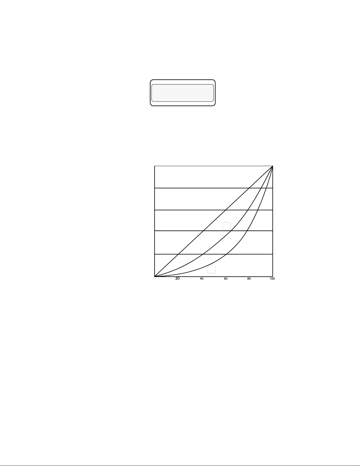
Setup
Heat/Cool Nonlinear Output Curve
Use this menu to select one of two nonlinear output curves for nonlinear
processes.
LOOP PROCESS UNITS
03 OUTPUTS HEAT
NLO ? OFF
ALARM SETPOINT STATUS OUT%
Selectable values: Curve 1, Curve 2, or Off (linear/no curve).
The linear curves are shown in the figure below. Calculated by PID
100
80
60
40
Output
20
0
0
100
90
80
79
Line ar
50
40
30
20
10
3
13
8
4
2
27
19
12
7
2
70
60
48
1
36
29
19
66
62
44
Calculated by PID
86 MLS User’s Guide
Page 99
Setup Loop Alarms
Setup
Press Yes at the Setup Loop Alarms prompt to access menus which
change alarm function parameters for the current loop. The main alarms
menu looks like this:
LOOP PROCESS UNITS
SETUP LOOP 04
ALARMS ?
ALARM SETPOINT STATUS OUT%
Below is the alarms menu tree. Notice the default values inside the
boxes.
Setup Loop Alarms?
High process
alarm setpoint?
ºF
1000
High process
alarm type?
OFF
High process alarm
dig out? NONE
Deviation alarm
value? 5
ºF
High deviation
alarm type? OFF
High deviation
alarm dig out?
NONE
Low deviation
alarm type? OFF
Low deviation
alarm dig out?
NONE
Low process
alarm setpoint?
ºF
0
Low process
alarm type? OFF
Low process
alarm dig out?
NONE
Alarm deadband?
2
ºF
Alarm delay?
0 Seconds
MLS User’s Guide 87
Page 100

Setup
Alarm Types
The MLS has three different kinds of alarms: failed sensor alarms,
global alarms, and process alarms.
Failed Sensor Alarms
Failed sensor alarms alert you to T/C breaks and these RTD open or
short failures:
• Open + or - input.
• Short between + and - input.
When the loop is in Automatic or Tune mode and a failed sensor alarm
occurs, the MLS sets the loop to Manual control at the failed sensor
percentage you set in the Setup Loop Outputs menus.
Global Alarms
Global alarms occur when a loop alarm, set to Alarm (not Control), is
unacknowledged, or when there are any unacknowledged failed sensor
alarms. (If an alarm occurs, the MLS front panel displays an appropriate
alarm code--see Chapter 4: Using the MLS for an explanation of these
codes.) Even if the alarm condition goes away, the global alarm stays on
until you use the Alarm Ack key (or ANASOFT) to acknowledge it.
Process Alarms
Process alarms include high and low deviation and high and lo w process
alarms. You can set each of these alarms to Off, Alarm, or Control, as
shown here.
Function Description
Off No alarm or control function
Alarm Standard alarm function
Control Normal alarm function, except that you
don’t have to ackowledge alarms
• High process and high deviation alarms activate when the process
variable goes above a value you set. They remain active until the
process variable goes below that value minus the deadband. (See
the diagram on the next page.)
• If you don’t use a digital output for PID control, you can assign it to
one or more process variable alarms. The output is active if any of
its alarms are active. All alarm outputs are active Low or active
High, depending on the global alarm output polarity setting.
• Low process and low deviation alarms activate when the process
variable goes below a value you set. They remain active until the
process variable goes above that value plus the deadband. (The diagram below shows these alarms.)
88 MLS User’s Guide
 Loading...