

Page 1
MINICHEFTM2000
97
Registered Company
Winona, Minnesota USA
ISO 9001
TOTAL
CUSTOMER
SATISFACTION
Applications 20 - 23
Griddle
Applications Guide
Programming & Operating Steps
Watlow Controls
1241 Bundy Blvd.
P.O. Box 5580
Winona, Minnesota U.S.A. 55987-5580
(507) 454-5300, Fax (507) 452-4507
WMC2-XAGN-0004-Rev A
May 1997
$5.00
Made in the U.S.A.
Page 2

20
Application 20
Automatic Clam Shell
Griddle
Dual Heat Channels, Six Menus
Introduction to Application 20 . . . . . . . . . . . . ....1
Configuration Mode Quick Reference . . . . . . . . . 3
Program Mode Quick Reference . . . . . . . . . . . . 4
Step 7 Design a Faceplate Overlay. . . . . . . . . . . 5
Step 8 Operate the Controller . . . . . . . . . . . . . . 6
Application 20 allows you to program as many as six menus, each of which can control
cooking temperatures and cooking times using a clam shell griddle (two-sided griddle).
For each menu, program two heat channels, Channel 1 (typically bottom griddle) and
Channel 2 (typically top griddle), and one cooking time.
Overview of Key Steps
1. Install the MINICHEF 2000.
2. Wire the controller.
3. Configure the controller.
4. Program the menus.
5. Set the controller security.
6. Set the Real-time Clock.
For instructions on Steps 1, 2, 3, 4, 5 and 6, see the Hardware & Software Setup
Guide.
7. Design, manufacture and apply faceplate overlay for end-users. (For a suggested
design to suit this application, see this section. For overlay dimensions and guidelines, see the Hardware & Software Setup Guide.)
8. Operate the controller. (See this application guide.)
Page 3
Key Functions in Configuration Mode
Input 1 Griddle Temp →
Input 2 Platen Temp →
Event Input 1 not used →
Event Input 2 not used →
→ Output 1 Griddle Heat
→ Output 2 Platen Heat
→ Event Output 1 not used
→ Event Output 2 not used
→ Output 5 Audible alarm
Heat
Menu
Menu
Menu
Menu
123
456
Your Company Logo
Menu
Menu
Heat
Heat
Menu
Menu
Menu
Menu
Menu
Menu
123
456
Your Company Logo
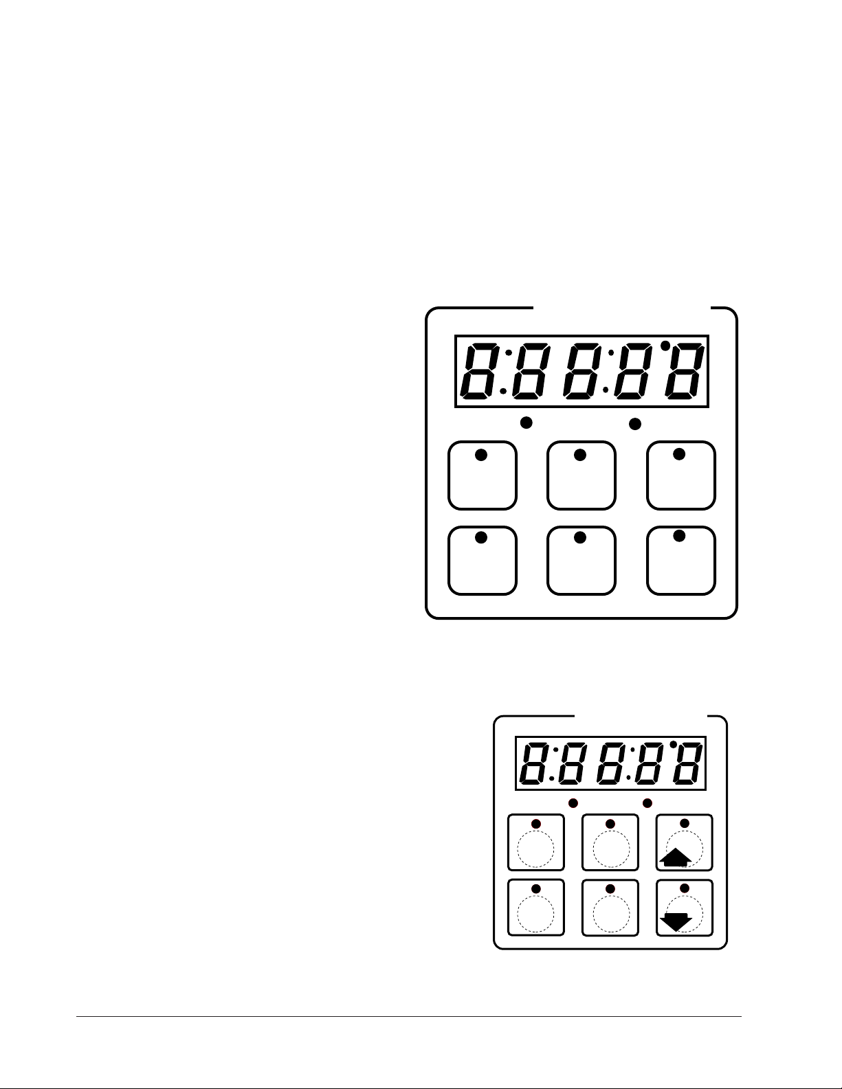
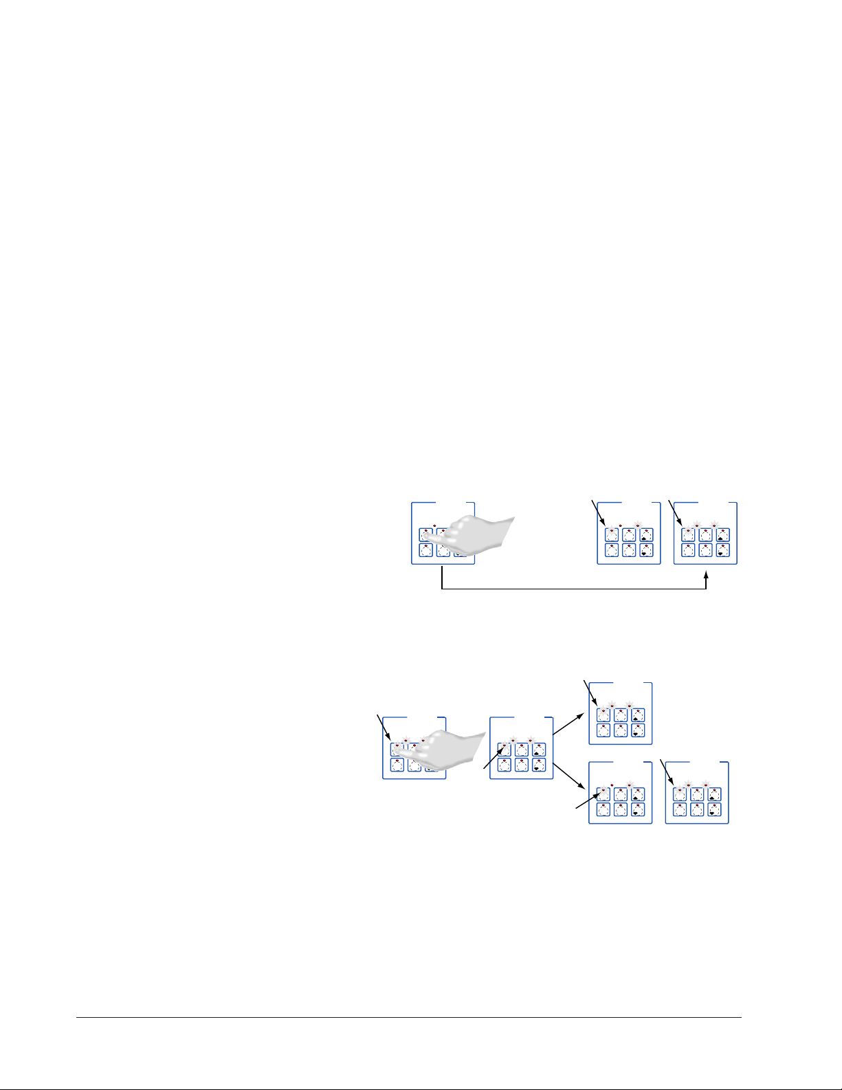
Menu Key Indicator Lights
Slow flash...Preheating
Rapid flash...Ready
Lit...Cooking
Rapid flash...Done
Slow flash...Idle and regulating
temp to previous set point
Not Lit...No menu selected
Heat Indicator Light Lit
when heat output is on.
Menu Keys Activate and
cancel menus, activate
cook cycle when
preheating, and
acknowledge alarms.
Heat
AB
DE
GH
Enter
EscapeHome
Edit
C
F
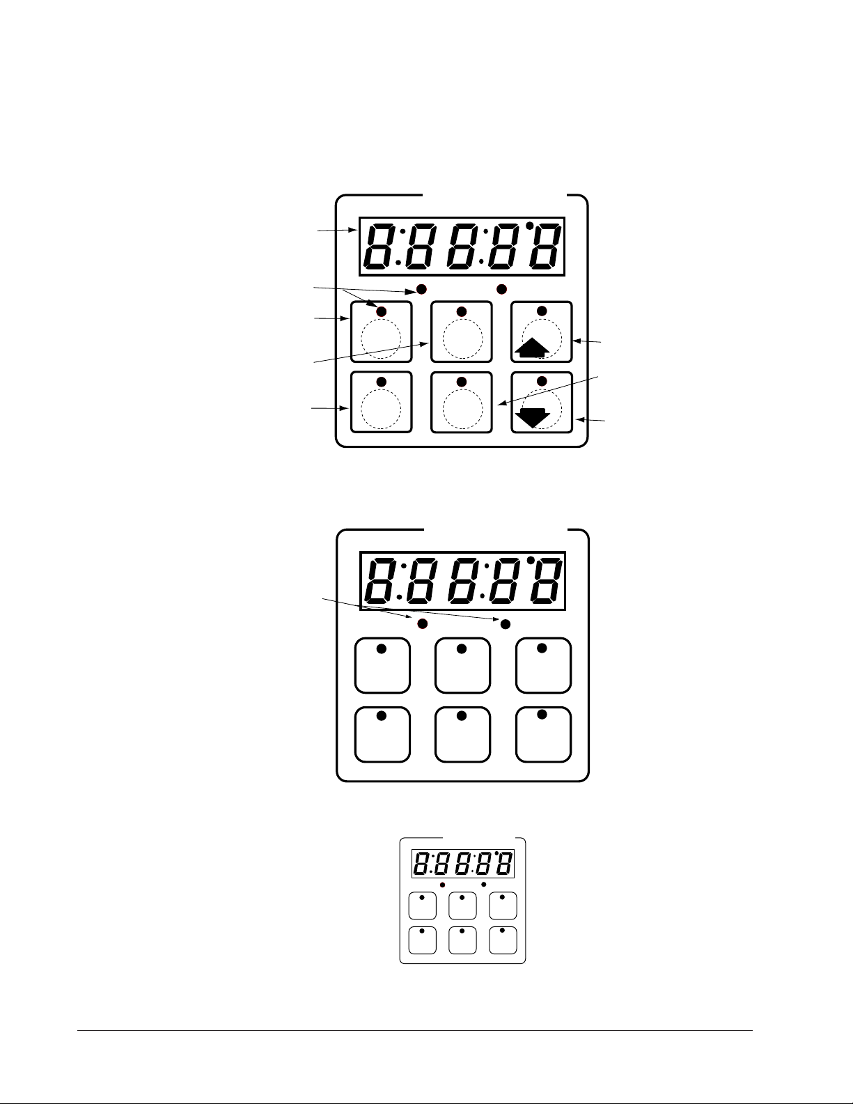
MINICHEF 2000
Display five-digit, sevensegment numeric LED
display.
Indicator lights
(1 for each key, 2 for heat
channels).
Edit key (A) Access the
next level of parameters or
values.
Enter key (B) Enter the
value and return to
previous level.
Home key (D) Move to
Operation Mode with a
two-second key press.
Up key (C) Move up the
lists.
Escape key (E) Return to
original value when editing
a parameter value.
Down key (F) Move down
the lists.
Key Functions in Operation Mode
Summary of Input/Output Functions
Note: For details, see wiring instructions in the
2 ■ Watlow MINICHEF 2000 Application 20
Hardware & Software Setup Guide
.
Page 4

Configuration Mode Quick Reference
These are the functions, parameters and values included in the Configuration Mode for
this application. You must select Application 20 to access them. For directions, see the
Hardware & Software Setup Guide. The Appendix of that guide includes an explanation
of all parameters and values.
Function Parameter Values Your Settings
[Etype] Equipment-Type [appl`] Application Number 1 - 28 20
[SEtUP] Setup [`Ç_Ï`] Temperature Display Format °C or °F
[tHErl] Thermal [tyPE`] Temperature Control Type Pid, On-Off
[`diag] WatHelp Used for equipment troubleshooting and testing. Not used when programming. See the Hardware
Diagnostics & Software Setup Guide.
[a_Loc] Application Number Yes, No
Security Lock
[Sound] Audible Alarm Sound 0 - 5
[time] Time Display Format MMM:SS, HH:MM, H:MM:SS
(H=Hours, M=Minutes, S=Seconds)
[Chirp] Key Chirp On, Off
[loc]``] Menu Security Lock Yes, No
[tc]```] Thermocouple Type J, K (shown as [````H]), E
[rtd``] RTD Curve DIN, JIS
[tconp] WatCurveTMTemperature On, Off
Compensation
[Ofst1] Temperature Offset Channel 1 -99 to 99°F (-55 to 55°C)
[Ofst2] Temperature Offset Channel 2 -99 to 99°F (-55 to 55°C)
[tr`lo] Temperature Range Low 0ºF (-18ºC) for rtd inputs
32ºF (0ºC) for tc inputs to [tr`Hi]
[tr`Hi] Temperature Range High [tr`lo] to 1200ºF/649ºC
[ready] Preheat Ready Feature Yes, No
[rband] Ready Band 1 to 1200°F (649°C)
[Cloc`] Real Time Clock Display Yes, No
[plOSS] Power Loss Menu Resume Yes, No
[al``1] Alarm for Channel 1 None, Dev, Proc, Both
[aL`P1] Absolute Process Alarm 1 100 to 1200°F (38 to 649°C)
[aLdL1] Low Deviation Alarm 1 -999 to 0°F (-555 to 0°C)
[aLdH1] High Deviation Alarm 1 0 to 999°F (0 to 555°C)
[AL``2] Alarm for Channel 2 None, Dev, Proc, Both
[AL`P2] Absolute Process Alarm 2 100 to 1200°F (38 to 649°C)
[aLdL2] Low Deviation Alarm 2 -999 to 0°F (-555 to 0°C)
[aLdH2] High Deviation Alarm 2 0 to 999°F (0 to 555°C)
[HYSt1] Hysteresis 1 1 to 99°F (1 to 55°C)
[HYSt2] Hysteresis 2 1 to 99°F (1 to 55°C)
[pid`U] PID units SI, US
[tune1] Auto-tuning 1 On, Off
[tune2] Auto-tuning 2 On, Off
[ProP1] Proportional Band 1 1 to 999°F (1 to 555°C)
[rSEt1] Reset (integral) Gain 1 0.00 to 9.99 repeats/minute
[int`1] Integral Gain 1 0.00 to 99.99 minutes/repeat
[rAtE1] Rate (derivative) Gain 1 0.00 to 9.99 minutes
[dEr`1] Derivative Gain 1 0.00 to 9.99 minutes
[CYcL1] PID Cycle Time 1 1 to 60 seconds
[ProP2] Proportional Band 2 1 to 999°F (1 to 555°C)
[rSEt2] Reset (integral) Gain 2 0.00 to 9.99 repeats/minute
[int`2] Integral Gain 2 0.00 to 99.99 minutes/repeat
[rAtE2] Rate (derivative) Gain 2 0.00 to 9.99 minutes
[dEr`2] Derivative Gain 2 0.00 to 9.99 minutes
[CYcL2] PID Cycle Time 2 1 to 60 seconds
Application 20
Watlow M
INICHEF
2000 ■ 3
Page 5

Program Mode Quick Reference
These are the functions, parameters and values included in the Program Mode for this
application. You must select Application 20 to access them. For menu programming
directions, see the Hardware & Software Setup Guide. The Appendix of that guide
includes a detailed explanation of all parameters and values.
Function Parameter Setting Your Settings
[M`--] [Stpt1
Menu Numbers 1 - 6 Temperature of channel 1. to temp range high.
[TiNe1] Time 1 Format varies based on
Menu run time. configuration. Setting at 0
[Stpt2] Set point 2 Temp range low
Auto-tuning Note:
Before auto-tuning Application 20 for zone 1, Set Point 1 of Menu 1 must first be set to
a value that is typical for zone 1. (See the Hardware & Software Setup Guide for information on programming menus.) Then set [tHErL] / [tunE1] to [```on]. After you
accept [```on], by pressing “Enter,” the controller will display [`tunE] while autotuning is taking place.
Then you can auto-tune zone 2, by first setting Set Point 1 of Menu 1 to a value that is
typical for zone 2. Then set [tHErL] / [tunE2] to [```on]. After you accept [```on],
the controller will display [`tunE] while auto-tuning is taking place.
The controller will cancel the auto-tuning process if it cannot be completed in 80 minutes. You can cancel the auto-tuning process at any time by pressing either key C or key
D and accepting [``Off], by pressing “Enter,” when it appears.
]
Set point 1 Temp range low
invalidates selected menu.
to temp range high.
4 ■ Watlow MINICHEF 2000 Application 20
Page 6
Step 7 Design a Faceplate Overlay
AB
DE
GH
Enter
EscapeHome
Edit
C
F
MINICHEF 2000
Menu
Menu
Menu
Menu
Menu
Menu
123
456
Your Company Logo
Heat
Heat
To complete the installation, you must apply a graphic membrane to the front panel of
the controller. The following artwork will help you design and create a membrane for
this application. For more dimensions and guidelines, see the Hardware & Software
Setup Guide.
Suggested End-user Overlay:
This Prototyping and Training Membrane Overlay will help you with the configuration and programming steps. To order it, see the Ordering Information
at the back of this guide.
Application 20 Watlow M
INICHEF
2000 ■ 5
Page 7
Step 8 Operating the Controller
AB
DECF
GH
MINICHEF 2000
[`idle]
Edit Accept
Back-UpExit
SLOW
FLASH
AT OPERATING TEMPERATURE
(PREHEAT CONDITION MET)
RAPID
FLASH
B
DECF
MINICHEF 2000
[100f`]
Edit Accept
Back-UpExit
B
DECF
MINICHEF 2000
[ready]
Edit Accept
Back-UpExit
G H GH
A A
[pre-`] [`Heat]
Summary of Key Functions
Key Function
A Menu 1
B Menu 2
C Menu 3
D Menu 4
E Menu 5
F Menu 6
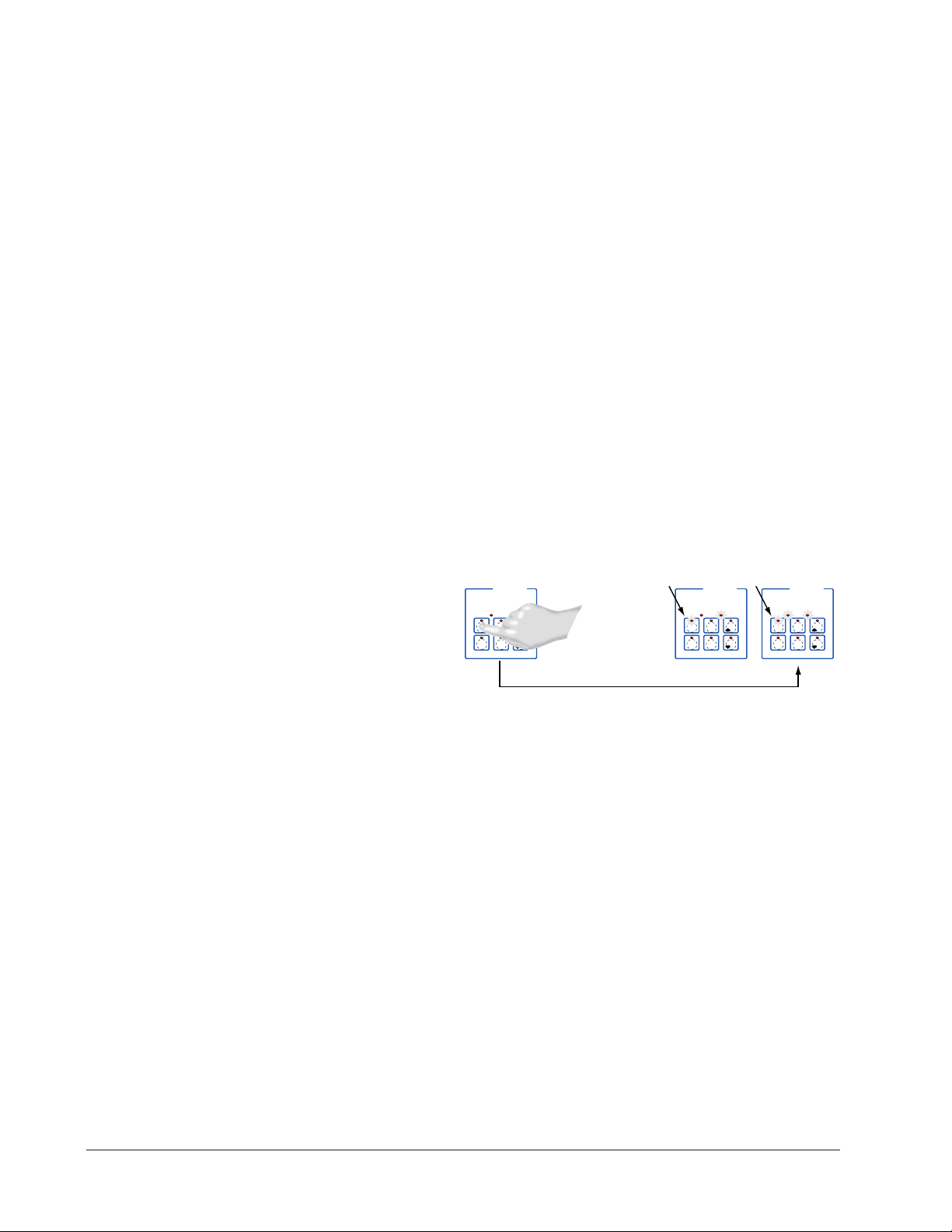
Startup
Apply power to the griddle.
[`iDle] will appear on the display.
If the Real-time Clock option is installed and [SetUp] / [CLoc`] = [``YES] the pre-
sent time of day will appear on the display.
Preheat
If the [Ready] parameter under the [SetUp] function in the Configuration mode is set
to [``yes], the controller will detect temperatures and preheat to operating temperature (above set point minus the ready band).
• Press the key for the menu you want to run. Each key selects a different menu. You
can select from up to six menus that control temperature and cooking time. Only
one menu may be run at a time.
Note: The controller will not respond if you select an invalid menu (one for which Time 1 is set to 0).
The menu you have chosen becomes the current menu for controller operation. Until
the menu is completed or canceled, the indicator light above the menu key will light
up (flashing or steady) to indicate the active menu.
• If the griddle is not at operating temperature, it will preheat. Meanwhile:
The word [Pre-`] [`Heat] will appear on the display for a few moments.
The menu key indicator light will flash slowly.
The temperature of Channel 1 will be displayed until the operating temperature for
both channels is reached.
6 ■ Watlow MINICHEF 2000 Application 20
Page 8
The heat output indicator lights (G & H, just below the display) will light up when-
DECF
MINICHEF 2000
[ready]
Edit Accept
Back-UpExit
DECF
MINICHEF 2000
[`0009]
Edit Accept
Back-UpExit
B
DECF
MINICHEF 2000
[`idle]
Edit Accept
Back-UpExit
G H
A
AB
GH
AB
GH
STEADY
ON
RAPID
FLASH
SLOW
FLASH
DECF
MINICHEF 2000
[``EnD]
Edit Accept
Back-UpExit
B
DECF
MINICHEF 2000
[`idle]
Edit Accept
Back-UpExit
G H
AAB
GH
RAPID
FLASH
SLOW
FLASH
AB
DECF
GH
MINICHEF 2000
[`idle]
Edit Accept
Back-UpExit
SLOW
FLASH
AT OPERATING TEMPERATURE
(PREHEAT CONDITION MET)
RAPID
FLASH
B
DECF
MINICHEF 2000
[100f`]
Edit Accept
Back-UpExit
B
DECF
MINICHEF 2000
[ready]
Edit Accept
Back-UpExit
G H GH
A A
[pre-`] [`Heat]
ever the controller is calling for heat.
When both channels are at operating temperature (set points minus the ready band)
[ready] will appear on the display and the menu key indicator light will flash
rapidly. You are now ready to cook with the active menu.
If the griddle is at operating temperature, the display goes directly to [Ready]
without indicating preheat or temperature.
Run a Menu (with preheat feature)
This procedure describes how to run an active menu when the preheat feature is active
(when the [Ready] parameter in the [SetUp] function of the Configuration Mode is set
to [```yes]).
1. With [`idle] or time of day on the display, press the key for the menu you want to
run.
If the preheat condition (temperatures >= set points minus the ready band) has not
been met, the griddle will preheat until [ready] appears on the display.
If the griddle is at operating temperature [ready] will appear on the display.
2. With [ready] on the display, place the food on the bottom griddle, lower the top
griddle, and press the active menu key (indicated by the rapidly flashing indicator
light).
The menu key indicator light will light up. Time will count down on the display.
3. Depending on how the controller was configured at [Etype] / [sound] the following will happen when the menu cycle is finished:
With Sound set to 0: The controller automatically switches to [`idle], where the
controller maintains the temperatures at set point and does not run time. [`idle]
or current time of day will appear on the display. The menu key indicator light
flashes slowly.
Application 20 Watlow M
If Sound is set to 1, 2, or 3, [``end] appears on the display and an audible tone
INICHEF
2000 ■ 7
Page 9
will be emitted. The menu key indicator light will flash rapidly. You can acknowl-
DECF
MINICHEF 2000
[ready]
Edit Accept
Back-UpExit
DECF
MINICHEF 2000
[`0009]
Edit Accept
Back-UpExit
B
DECF
MINICHEF 2000
[`idle]
Edit Accept
Back-UpExit
G H
A
AB
GH
AB
GH
STEADY
ON
RAPID
FLASH
SLOW
FLASH
DECF
MINICHEF 2000
[``EnD]
Edit Accept
Back-UpExit
B
DECF
MINICHEF 2000
[`idle]
Edit Accept
Back-UpExit
G H
AAB
GH
RAPID
FLASH
SLOW
FLASH
edge and silence the tone by pressing the active menu key, or it will automatically
time out within 20 seconds and go into idle while the menu key indicator light flashes slowly.
If Sound is set to 4 or 5, [``end] will appear on the display and the menu key indicator light will flash rapidly. You must acknowledge the audible tone by pressing the
active menu key. Once acknowledged, the audible tone is silenced and the controller
goes into idle.The menu key indicator light will flash slowly.
4. Raise the top griddle and remove the food.
The controller will continue to regulate at the last set point that was run. The menu
key indicator light will flash slowly.
5. To repeat cooking, repeat steps 1 through 4.
Run a Menu (without preheat feature)
This procedure describes how to run an active menu when the preheat feature is inactive (when the [Ready] parameter in the [SetUp] function of the Configuration Mode
is set to [```no]).
1. With [`idle] or time of day on the display, place the food on the griddle.
2. Lower the top griddle and press they key for the menu you want to run.
The menu key indicator light will light up. Time will count down on the display.
3. Depending on how the controller was configured at [Etype] / [sound] the following will happen when the menu cycle is finished:
With Sound set to 0: The controller automatically switches to [`idle], where the
controller maintains the temperatures at set point and does not run time. [`idle]
or current time of day will appear on the display. The menu key indicator light
flashes slowly.
If Sound is set to 1, 2, or 3, [``end] appears on the display and an audible tone
will be emitted. The menu key indicator light will flash rapidly. You can acknowledge and silence the tone by pressing the active menu key, or it will automatically
time out within 20 seconds and go into idle while the menu key indicator light flashes slowly.
If [Sound] is set to 4 or 5, [``end] will appear on the display and the menu key
indicator light will flash rapidly. You must acknowledge the audible tone by pressing
the active menu key. Once acknowledged, the audible tone is silenced and the controller goes into idle.The menu key indicator light will flash slowly.
4. Raise the top griddle and remove the food.
8 ■ Watlow MINICHEF 2000 Application 20
Page 10

The controller will continue to regulate at the last set point that was run. The menu
key indicator light will flash slowly.
5. To repeat cooking, repeat steps 1 through 4.
Cancel a Menu
Canceling a menu stops controller operation completely. The controller does not maintain set point temperatures or run time. You cancel a menu to run another menu, stop
menu operation for any reason, or are preparing to shut off the griddle.
• Press the active menu key for 2 seconds.
Heat outputs will switch off. Heat output indicator lights will switch off. [`idle]
or the time of day will be on display.
Change Menus or Restart
1. If the controller is preheating or running a menu, cancel the menu by pressing and
holding the active menu key for 2 seconds. If the controller is in [`idle] go to 2.
2. Press the key for the menu you want to run.
Based on its programming, the unit will run the menu in one of the ways described
earlier.
Temperature Alarms
The controller will alert you to temperature alarm conditions if they occur. If an alarm
occurs, take action as determined by your supervisor. See the Appendix in the Hardware
& Software Setup Guide for a Troubleshooting Chart and a summary of temperature
alarms.
Errors
The controller will alert you to errors if they occur. Errors are critical problems that
shut down the unit. If an error occurs, an error message will appear on the display. You
should switch off the power and call for service.
See the Appendix in the Hardware & Software Setup Guide for a Troubleshooting Chart
and a summary of errors.
Application 20 Watlow M
INICHEF
2000 ■ 9
Page 11

Notes
10 ■ Watlow MINIC HEF 2000 Application 20
Page 12

21
Application 21
Manual Clam Shell Griddle
Two Heat Channels
Introduction to Application 21 . . . . . . . . . . . . . 11
Configuration Mode Quick Reference . . . . . . . . 13
Step 7 Design a Faceplate Overlay . . . . . . . . . . 15
Step 8 Operate the Controller . . . . . . . . . . . . . 16
Application 21 allows you to control cooking temperatures and cooking times using a
clam shell griddle (two-sided griddle). There are two heat channels, Channel 1 (typically
bottom griddle) and Channel 2 (typically top griddle), and one cooking time.
Overview of Key Steps
1. Install the MINICHEF 2000.
2. Wire the controller.
3. Configure the controller.
4. Program the menu.
5. Set the controller security.
6. Set the Real-time Clock.
For instructions on Steps 1, 2, 3, 4, 5 and 6, see the Hardware & Software Setup Guide.
7. Design, manufacture and apply faceplate overlay for end-users. (For a suggested
design to suit this application, see this section. For overlay dimensions and guidelines, see the Hardware & Software Setup Guide.)
8. Operate the controller. (See this application guide.)
Page 13
Key Functions in Configuration Mode
Heat
1
Cook
Temp(s)
2
Cook
Time(s)
4
5
Start/
Stop
6
Down
Your Company Logo
3
Up
Input 1 Griddle Temp →
Input 2 Platen Temp →
Event Input 1 not used→
Event Input 2 not used→
→ Output 1 Griddle Heat
→ Output 2 Platen Heat
→ Event Output 1 not used
→ Event Output 2 Timer Output
→ Output 5 Audible Alarm
Heat
Heat
1
Cook
Temp(s)
2
Cook
Time(s)
4
5
Start/
Stop
6
Down
Your Company Logo
3
Up
Temp Set or display
temperature. Lights flash
rapidly if editing
parameters during menu
operation.
Time Set Time. Lights
flash rapidly if editing
parameters during menu
operation.
Not Used
Start/Stop Activate, pause
or cancel active menu.
Heat Indicator Lights
Lit when either heat output
is on.
Increment
Start/Stop Indicator Light
Slow flash...Preheating
Rapid flash...Ready
Lit...Cooking
Off...Done
Decrement
Heat
AB
DE
GH
Enter
EscapeHome
Edit
C
F
MINICHEF 2000
Display five-digit, sevensegment numeric LED
display.
Indicator lights
(1 for each key, 2 for heat
channels).
Edit key (A) Access the
next level of parameters or
values.
Enter key (B) Enter the
value and return to
previous level.
Home key (D) Move to
Operation Mode with a
two-second key press.
Up key (C) Move up the
lists.
Escape key (E) Return to
original value when editing
a parameter value.
Down key (F) Move down
the lists.
Key functions in Operation Mode
Summary of Input/Output Functions
Note: For details, see wiring instructions in the
12 ■ Watlow MINIC HEF 2000 Application 21
Hardware & Software Setup Guide.
Page 14

Configuration Mode Quick Reference
These are the functions, parameters and values included in the Configuration Mode for
this application. You must select Application 21 to access them. For directions, see the
Hardware & Software Setup Guide. The Appendix of that guide includes an explanation
of all parameters and values.
Function Parameter Value Your Settings
{Etype} Equipment-Type [appl`] Application Number 1 - 28 21
[a_Loc] Application Number Yes, No
[T`OUt] Timer Output No, Yes
[SEtUP] Setup [`Ç_Ï`] Temperature Display Format °C or °F
[time] Time Display Format MMM:SS, HH:MM, H:MM:SS
[Chirp] Key Chirp On, Off
[tc```] Thermocouple Type J, K (shown as [````H]), E
[rtd``] RTD Curve DIN, JIS
[tconp] WatCurveTMTemperature On, Off
[Ofst1] Temperature Offset Channel 1 -99 to 99°F (-55 to 55°C)
[Ofst2] Temperature Offset Channel 2 -99 to 99°F (-55 to 55°C)
[tr`lo] Temperature Range Low 0ºF (-18º C) for rtd inputs,
[tr`Hi] Temperature Range High [tr`lo] to 1200ºF (649ºC)
[ready] Preheat Ready Feature Yes, No
[rband] Ready Band 1 to 1200°F (649°C)
[Cloc`] Real Time Clock Display Yes, No
[plOSS] Power Loss Menu Resume Yes, No
[al``1] Alarms for channel 1 None, Dev, Proc, Both
[aL`P1] Absolute Process Alarm 1 100 to 1200°F (38 to 649°C)
[aLdL1] Low Deviation Alarm 1 -999 to 0°F (-555 to 0°C)
[aLdH1] High Deviation Alarm 1 0 to 999°F (0 to 555°C)
[AL``2] Alarm for channel 2 None, Dev, Proc, Both
[AL`P2] Absolute Process Alarm 2 100 to 1200°F (38 to 649°C)
[aLdL2] Low Deviation Alarm 2 -999 to 0°F (-555 to 0°C)
[aLdH2] High Deviation Alarm 2 0 to 999°F (0 to 555°C)
[tHErl] Thermal [tyPE`] Temperature Control Type PID, On-Off
[HYSt1] Hysteresis 1 1 to 99°F (1 to 55°C)
[HYSt2] Hysteresis 2 1 to 99°F (1 to 55°C)
[Pid`U] PID Units SI, US
[tune1] Auto-tuning 1 on, OFF
[tune2] Auto-tuning 2 on, OFF
[ProP1] Proportional Band 1 1 to 999°F (1 to 555°C)
[rSEt1] Reset (integral) Gain 1 0.00 to 9.99 repeats/minute
[int`1] Integral Gain 1 0.00 to 99.99 minutes/repeat
[rAtE1] Rate (derivative) Gain 1 0.00 to 9.99 minutes
[dEr`1] Derivative Gain 1 0.00 to 9.99 minutes
[CYcL1] PID Cycle Time 1 1 to 60 seconds
[ProP2] Proportional Band 2 1 to 999°F (1 to 555°C)
[rSEt2] Reset (integral) Gain 2 0.00 to 9.99 repeats/minute
[int`2] Integral Gain 2 0.00 to 99.99 minutes/repeat
[rAtE2] Rate (derivative) Gain 2 0.00 to 9.99 minutes
[dEr`2] Derivative Gain 2 0.00 to 9.99 minutes
[CYcL2] PID Cycle Time 2 1 to 60 seconds
`diag] WatHelp Used for equipment troubleshooting and testing. Not used when programming. See the Hardware
Diagnostics & Software Setup Guide.
Security Lock
(H=Hours, M=Minutes, S=Seconds)
Compensation
32ºF (0ºC) for tc inputs to [tr`Hi]
Application 21 Watlow MINICHEF 2000 ■ 13
Page 15

Auto-tuning Note:
Before auto-tuning Application 21 for zone 1, [TeNp1] must first be set to a value that
is typical for zone 1. (See the Hardware & Software Setup Guide for information on programming menus.) Then set [tHErL] / [tunE1] to [```on]. After you accept [```on],
by pressing “Enter,” the controller will display [`tunE] while auto-tuning is taking
place.
Then you can auto-tune zone 2, by first setting [TeNp1] of Menu 1 to a value that is
typical for zone 2. Then set [tHErL] / [tunE2] to [```on]. After you accept [```on],
by pressing “Enter,” the controller will display [`tunE] while auto-tuning is taking
place.
The controller will cancel the auto-tuning process if it cannot be completed in 80 minutes. You can cancel the auto-tuning process at any time by pressing either key C or key
D and accepting [``Off], by pressing “Enter,” when it appears.
14 ■ Watlow MINIC HEF 2000 Application 21
Page 16

Step 7 Design a Faceplate Overlay
AB
DE
GH
Enter
EscapeHome
Edit
C
F
MINICHEF 2000
Heat
1
Cook
Temp(s)
2
Cook
Time(s)
4
5
6
Down
Your Company Logo
Start/
Stop
3
Up
Heat
To complete the installation, you must apply a graphic membrane to the front panel of
the controller. The following artwork will help you design and create a membrane for
this application. For more dimensions and guidelines, see the Hardware & Software
Setup Guide.
Suggested End-user Overlay:
This Prototyping and Training Membrane Overlay will help you with the configuration and programming steps. To order it, see the Ordering Information
at the back of this guide.
Application 21 Watlow MINICHEF 2000 ■ 15
Page 17

Step 8 Operate the Controller
DECF
MINICHEF 2000
[tENP1]
Edit Accept
Back-UpExit
DECF
MINICHEF 2000
[650°f]
Edit Accept
Back-UpExit
AB
GH
AB
GH
DECF
MINICHEF 2000
[`idle]
Edit Accept
Back-UpExit
AB
GH
[500°F]
Summary of Key Functions in Operation Mode
Key Operation Function
A Cook Temp(s)
B Cook Time
C Up (Increment)
D Not Used
E Start/Stop
F Down (Decrement)
Startup
Apply power to the griddle.
[`iDle] will appear on the display.
If the Real-time Clock option is installed and [SetUp] / [CLoc`] = [``YES] the pre-
sent time of day will appear on the display.
Set the Menu
Set the cooking temperatures.
1. Press the Cook Temp key for [teNp1] and then the cooking temperature value will
appear on the display.
2. Press the Up-arrow or Down-arrow key until the value you want appears on the dis-
play.
3. Press the Cook Temp key again for [teNp2] and repeat steps 1 and 2.
4 Press the Cook Temp key again.
The cooking temperatures have been set.
[`idle] will appear on the display.
Set the cooking time.
1. Press the Cook Time key [tiNE1] and then the cooking time value will appear on
the display.
2. Press the Up-arrow or Down-arrow key until the value you want appears on the dis-
play.
16 ■ Watlow MINIC HEF 2000 Application 21
Page 18

3. Press the Cook Time key again.
AB
DECF
GH
MINICHEF 2000
[`idle]
Edit Accept
Back-UpExit
SLOW
FLASH
AT OPERATING TEMPERATURE
(PREHEAT CONDITION MET)
RAPID
FLASH
B
DECF
MINICHEF 2000
[100f`]
Edit Accept
Back-UpExit
B
DECF
MINICHEF 2000
[ready]
Edit Accept
Back-UpExit
G H GH
A A
[pre-`] [`Heat]
The cooking time has been set.
[`idle] will appear on the display.
Five Second Timeout
When using the up or down keys to change a value, if you do not press any key for 5
seconds, the controller will automatically be set to the last value on the display and
return to [`idle].
Preheat
If the [Ready] parameter under the [SetUp] function in the Configuration mode is set
to [``yes], the controller will detect temperatures and preheat to operating temperature (above set point minus the ready band).
Note: The controller will not respond if Time1 is set to 0.
• If the griddle is not at operating temperature, it will preheat. Meanwhile:
The word [Pre-`] [`Heat] will appear on the display for a few moments.
The Start/Stop key indicator light will flash slowly.
The temperature of Channel 1 will be displayed until the operating temperature for
both channels is reached.
The heat output indicator lights (G & H, just below the display) will light up when-
ever the controller is calling for heat.
When both channels are at operating temperature (set points minus the ready band)
[ready] will appear on the display and the Start/Stop key indicator light will flash
rapidly. You are now ready to cook with the active menu.
• If the griddle is at operating temperature, the display goes directly to [Ready]
without indicating preheat or temperature.
Run a Menu (with preheat feature)
This procedure describes how to run an active menu when the preheat feature is active
(when the [Ready] parameter in the [SetUp] function of the Configuration Mode is set
to [``yes]).
1. Set the menu as shown earlier.
2. With [`idle] or time of day on the display, press the Start/Stop key.
If the preheat condition (temperatures >= set points minus the ready band) has not
been met, the griddle will preheat until [ready] appears on the display.
If the griddle is at operating temperature [ready] will appear on the display.
Application 21 Watlow MINICHEF 2000 ■ 17
Page 19
3. With [ready] on the display, place the food on the bottom griddle, lower the top
DECF
MINICHEF 2000
[`idle]
Edit Accept
Back-UpExit
DECF
MINICHEF 2000
[`0009]
Edit Accept
Back-UpExit
B
DECF
MINICHEF 2000
[`idle]
Edit Accept
Back-UpExit
G H
A
AB
GH
AB
GH
STEADY
ON
SLOW
FLASH
DECF
MINICHEF 2000
[``EnD]
Edit Accept
Back-UpExit
B
DECF
MINICHEF 2000
[`idle]
Edit Accept
Back-UpExit
G H
AAB
GH
RAPID FLASH
SLOW FLASH
DECF
MINICHEF 2000
[ready]
Edit Accept
Back-UpExit
DECF
MINICHEF 2000
[`0009]
Edit Accept
Back-UpExit
B
DECF
MINICHEF 2000
[`idle]
Edit Accept
Back-UpExit
G H
A
AB
GH
AB
GH
STEADY
ON
RAPID
FLASH
SLOW
FLASH
DECF
MINICHEF 2000
[``EnD]
Edit Accept
Back-UpExit
B
DECF
MINICHEF 2000
[`idle]
Edit Accept
Back-UpExit
G H
AAB
GH
RAPID FLASH
SLOW FLASH
griddle, and press the Start/Stop key(indicated by the rapidly flashing indicator
light).
The Start/Stop indicator light will light up. Time will count down on the display.
4. When the cooking cycle is finished, the controller goes into idle and the Start/Stop
key indicator light will switch off. The controller will regulate to the setpoint temperature.
5. Raise the top griddle and remove the food.
6. To repeat cooking, repeat steps 2 through 5.
Run a Menu (without preheat feature)
This procedure describes how to run an active menu when the preheat feature is inactive (when the [Ready] parameter in the [SetUp] function of the Configuration Mode
is set to [```no]).
1. Set the menu as shown earlier.
2. With [`idle] or time of day on the display, press the Start/Stop key.
3. Lower the top griddle and press the Start/Stop key.
The Start/Stop indicator light will light up. Time will count down on the display.
4. When the cooking cycle is finished, the controller goes into idle and the Start/Stop
key indicator light will switch off. The controller will regulate to the setpoint temperature.
5. Raise the top griddle and remove the food.
6. To repeat cooking, repeat steps 2 through 5.
Cancel a Menu
18 ■ Watlow MINIC HEF 2000 Application 21
Canceling a menu stops controller operation completely. The controller does not main-
Page 20

tain set point temperatures or run time. You cancel a menu to run another menu, stop
menu operation for any reason, or are preparing to shut off the griddle.
• Press the Start/Stop for 2 seconds.
Heat outputs will switch off. Heat output indicator lights will switch off. [`idle]
or the time of day will be on display.
Adjust a Menu While Cooking
You can adjust the temperature and time settings during the cooking and hold
sequences by performing the actions shown under “Set the Menu” earlier in this section.
Changes can be made to temperature and time only during the portion of the cooking
sequence in which they are active. For example: a change to the first cooking temperature [tENP1] can be made only when the first cooking temperature is being run during
the cooking sequence.
Temperature changes made while cooking are saved and become part of the permanent
menu. Time changes are not saved and do not become part of the permanent menu.
Change Menus or Restart
1. If the controller is preheating or running the menu, cancel the menu by pressing
and holding the Start/Stop for 2 seconds. If the controller is in [`idle] go to 2.
2. Press the Start/Stop key.
Based on its programming, the unit will run the menu in one of the ways described
earlier.
Timer Output
If [Etype]] / [T`OUt]] in the Configuration Mode is set to [``yes], when time is counting down Event Output 2 is on. It is off during [PaUse], [`Idle] or [Hold].
Temperature Alarms
The controller will alert you to temperature alarm conditions if they occur. If an alarm
occurs, take action as determined by your supervisor. See the Appendix in the Hardware
& Software Setup Guide for a Troubleshooting Chart and a summary of temperature
alarms.
Errors
The controller will alert you to errors if they occur. Errors are critical problems that
shut down the unit. If an error occurs, an error message will appear on the display. You
should switch off the power and call for service.
See the Appendix in the Hardware & Software Setup Guide for a Troubleshooting Chart
and a summary of errors.
Application 21 Watlow MINICHEF 2000 ■ 19
Page 21

Notes
20 ■ Watlow MINIC HEF 2000 Application 21
Page 22

22
Application 22
Automatic One-Sided
Griddle
One Heat Channel, Six Menus
Introduction to Application 22 . . . . . . . . . . . . . 21
Configuration Mode Quick Reference . . . . . . . . 23
Program Mode Quick Reference. . . . . . . . . . . . 24
Step 7 Design a Faceplate Overlay . . . . . . . . . . 25
Step 8 Operate the Controller . . . . . . . . . . . . . 26
Application 22 allows you to program as many as six menu keys to control one temperature channel and cooking time for an automatic one-sided griddle.
Overview of Key Steps
1. Install the MINICHEF 2000.
2. Wire the controller.
3. Configure the controller.
4. Program the menus.
5. Set the controller security.
6. Set the Real-time Clock.
For instructions on Steps 1, 2, 3, 4, 5 and 6, see the Hardware & Software Setup Guide.
7. Design, manufacture and apply faceplate overlay for end-users. (For a suggested
design to suit this application, see this section. For overlay dimensions and guidelines, see the Hardware & Software Setup Guide.)
8. Operate the controller. (See this application guide.)
Page 23

Key Functions in Configuration Mode
Input 1 Griddle Temp →
Input 2 not used →
Event Input 1 not used →
Event Input 2 not used →
→ Output 1 Heat
→ Output 2 not used
→ Event Output 1 not used
→ Event Output 2 not used
→ Output 5 Audible alarm
Heat
Menu
Menu
Menu
Menu
123
456
Your Company Logo
Menu
Menu
Heat
Menu
Menu
Menu
Menu
Menu
Menu
123
456
Your Company Logo
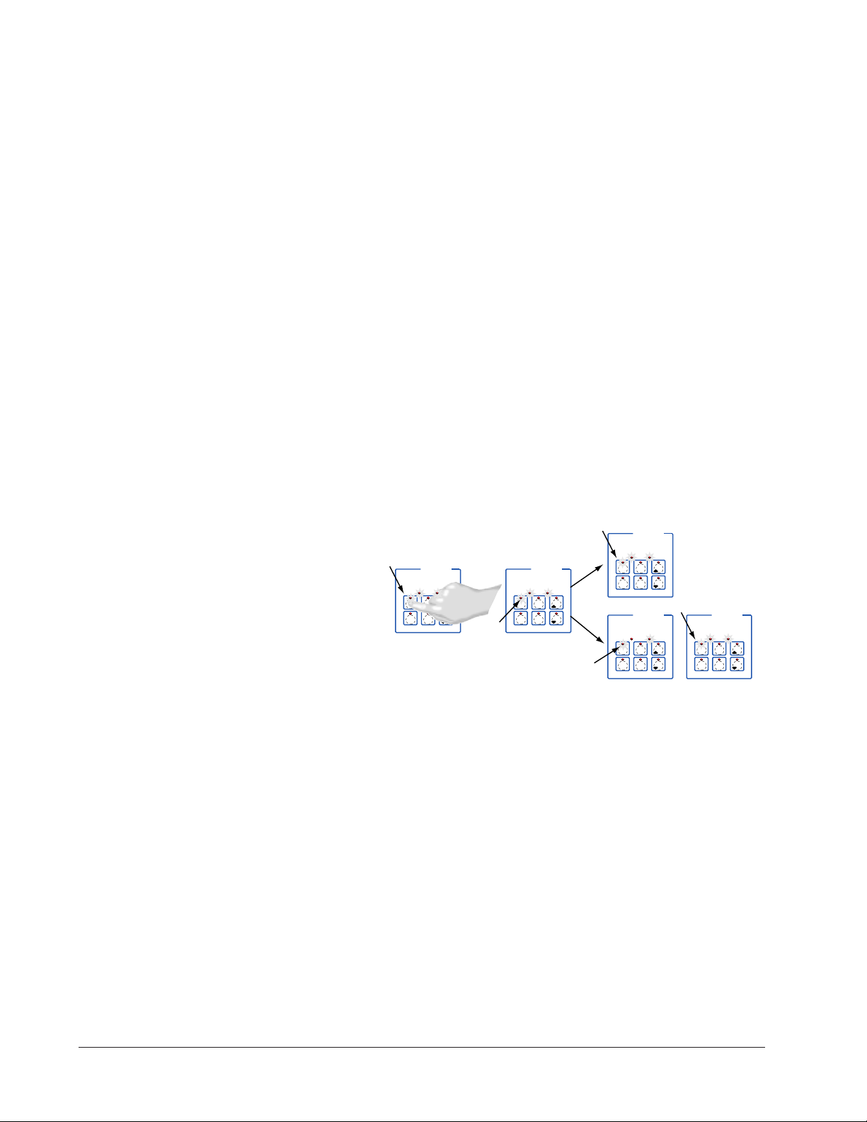
Menu Key Indicator
Lights
Slow flash.........Preheating
Rapid flash...............Ready
Lit..........................Cooking
Rapid flash.................Done
Slow flash..............Idle and
regulating temp to
previous set point
Not lit.....No menu selected
Heat Indicator Light Lit
when heat output is on.
Menu Keys Activate and
cancel menus, activate
cook cycle when
preheating, and
acknowledge alarms.
AB
DE
GH
Enter
EscapeHome
Edit
C
F
MINICHEF 2000
Display five-digit, sevensegment numeric LED
display.
Indicator lights
(1 for each key, 2 for heat
channels).
Edit key (A) Access the
next level of parameters or
values.
Enter key (B) Enter the
value and return to
previous level.
Home key (D) Move to
Operation Mode with a
two-second key press.
Up key (C) Move up the
lists.
Escape key (E) Return to
original value when editing
a parameter value.
Down key (F) Move down
the lists.
Key Functions in Operation Mode
Summary of Input/Output Functions
Note: For details, see wiring instructions in the
22 ■ Watlow MINIC HEF 2000 Application 22
Hardware & Software Setup Guide.
Page 24

Configuration Mode Quick Reference
These are the functions, parameters and values included in the Configuration Mode for
this application. You must select Application 22 to access them. For directions, see the
Hardware & Software Setup Guide. The Appendix of that guide includes an explanation
of all parameters and values.
Function Parameter Value Your Settings
{Etype} Equipment-Type [appl`] Application Number 1 - 28 22
[a_Loc] Application Number Yes, No
Security Lock
[Sound] Audible Alarm Sound 0 - 5
[SEtUP] Setup [`Ç_Ï`] Temperature Display Format °C or °F
[time] Time Display Format MMM:SS, HH:MM, H:MM:SS
(H=Hours, M=Minutes, S=Seconds)
[Chirp] Key Chirp On, Off
[loc``] Menu Security Lock Yes, No
[tc```] Thermocouple Type J, K (shown as [````H]), E
[rtd``] RTD Curve DIN, JIS
[tconp] WatCurveTMTemperature On, Off
Compensation
[Ofst1] Temperature Offset, Channel 1 -99 to 99°F (-55 to 55°C)
[tr`lo] Temperature Range Low 0ºF (-18ºC) for rtd inputs,
32ºF (0ºC) for tc inputs to [tr`Hi]
[tr`Hi] Temperature Range High [tr`lo] to 1200ºF (649ºC)
[ready] Preheat Ready Feature Yes, No
[rband] Ready Band 1 to 1200°F (649°C)
[Cloc`] Real Time Clock Display Yes, No
[plOSS] Power Loss Menu Resume Yes, No
[al``1] Alarms for channel 1 None, Dev, Proc, Both
[aL`P1] Absolute Process Alarm 1 100 to 1200°F (38 to 649°C)
[aLdL1] Low Deviation Alarm 1 -999 to 0°F (-555 to 0°C)
[aLdH1] High Deviation Alarm 1 0 to 999°F (0 to 555°C)
[tHErl] Thermal [tyPE`] Temperature Control Type PID, On-Off
[HYSt1] Hysteresis 1 1 to 99°F (1 to 55°C)
[Pid`U] PID Units SI, US
[tune1] Auto-tuning 1 on, OFF
[ProP1] Proportional Band 1 1 to 999°F (1 to 555°C)
[rSEt1] Reset (integral) Gain 1 0.00 to 9.99 repeats/minute
[int`1] Integral Gain 1 0.00 to 99.99 minutes/repeat
[rAtE1] Rate (derivative) Gain 1 0.00 to 9.99 minutes
[dEr`1] Derivative Gain 1 0.00 to 9.99 minutes
[CYcL1] PID Cycle Time 1 1 to 60 seconds
`diag] WatHelp Used for equipment troubleshooting and testing. Not used when programming. See the Hardware
Diagnostics & Software Setup Guide.
Application 22 Watlow MINICHEF 2000 ■ 23
Page 25

Program Mode Quick Reference
These are the functions, parameters and values included in the Program Mode for this
application. You must select Application 22 to access them. For menu programming
directions, see the Hardware & Software Setup Guide. The Appendix of that guide
includes a detailed explanation of all parameters and values.
Function Parameter Value Your Settings
[M`__] Menu Numbers 1 - 6 [Stpt1] Set point 1 Temp range low
Temperature of set point 1. to temp range high
[TiNe1] Time 1 Format varies based
Run time of set point 1. on configuration.
[alarn] Mid-menu Stir, Add, Flip, Turn, Alert,
Alarm None
[atine] Mid-menu 0 to Time 1
alarm time.
Auto-tuning Note:
Before auto-tuning Application 22, the Set Point 1 of Menu 1 must first be set to a value
that is typical of your application. (See the Hardware & Software Setup Guide for information on programming menus.) Then set [tHerl] / [tunE1] to [```on]. After you
accept [```on], by pressing “Enter,” the controller will display [`tunE] while autotuning is taking place.
The controller will cancel the auto-tuning process if it cannot be completed in 80 minutes. You can cancel the auto-tuning process at any time by pressing either key C or key
D and accepting [``Off], by pressing “Enter,” when it appears.
24 ■ Watlow MINIC HEF 2000 Application 22
Page 26

Step 7 Design a Faceplate Overlay
AB
DE
GH
Enter
EscapeHome
Edit
C
F
MINICHEF 2000
Heat
Menu
Menu
Menu
Menu
Menu
Menu
123
456
Your Company Logo
To complete the installation, you must apply a graphic membrane to the front panel of
the controller. The following artwork will help you design and create a membrane for
this application. For more dimensions and guidelines, see the Hardware & Software
Setup Guide.
Suggested End-user Overlay:
This Prototyping and Training Membrane Overlay will help you with the configuration and programming steps. To order it, see the Ordering Information
at the back of this guide.
Application 22 Watlow MINICHEF 2000 ■ 25
Page 27

Step 8 Operate the Controller
AB
DECF
GH
MINICHEF 2000
[`idle]
Edit Accept
Back-UpExit
SLOW
FLASH
AT OPERATING TEMPERATURE
(PREHEAT CONDITION MET)
RAPID
FLASH
B
DECF
MINICHEF 2000
[100f`]
Edit Accept
Back-UpExit
B
DECF
MINICHEF 2000
[ready]
Edit Accept
Back-UpExit
G H GH
A A
[pre-`] [`Heat]
Summary of Key Functions in Operation Mode
Key Function
A Menu 1
B Menu 2
C Menu 3
D Menu 4
E Menu 5
F Menu 6
Startup
Apply power to the griddle.
[`iDle] will appear on the display.
If the Real-time Clock option is installed and [SetUp] / [CLoc`] = [``YES] the pre-
sent time of day will appear on the display.
Preheat
If the [Ready] parameter under the [SetUp] function in the Configuration Mode is set
to [``yes]], the controller will detect the temperature and preheat to operating temperature (above set point minus the ready band).
• Press the key for the menu you want to run. Each key selects a different menu. You
can select from up to six menus that control temperature and cooking time. Only
one menu may be run at a time.
Note: The controller will not respond if you select an invalid menu (one for which Time1 is set to 0).
The menu you have chosen becomes the current menu for controller operation. Until
the menu is completed or canceled , the indicator light above the menu key will
light up (flashing or steady) to indicate the active menu.
• If the griddle is not at operating temperature, it will preheat. Meanwhile:
The word [Pre-`] [`Heat] will appear on the display for a few moments.
The menu key indicator light will flash slowly.
The temperature of Channel 1 will be displayed until the operating temperature for
Channel 1 is reached.
26 ■ Watlow MINIC HEF 2000 Application 22
Page 28

The heat output indicator light (G, just below the display) will light up whenever
DECF
MINICHEF 2000
[ready]
Edit Accept
Back-UpExit
DECF
MINICHEF 2000
[`0009]
Edit Accept
Back-UpExit
B
DECF
MINICHEF 2000
[`idle]
Edit Accept
Back-UpExit
G H
A
AB
GH
AB
GH
STEADY
ON
RAPID
FLASH
SLOW
FLASH
DECF
MINICHEF 2000
[``EnD]
Edit Accept
Back-UpExit
B
DECF
MINICHEF 2000
[`idle]
Edit Accept
Back-UpExit
G H
AAB
GH
RAPID
FLASH
SLOW
FLASH
AB
DECF
GH
MINICHEF 2000
[`idle]
Edit Accept
Back-UpExit
SLOW
FLASH
AT OPERATING TEMPERATURE
(PREHEAT CONDITION MET)
RAPID
FLASH
B
DECF
MINICHEF 2000
[100f`]
Edit Accept
Back-UpExit
B
DECF
MINICHEF 2000
[ready]
Edit Accept
Back-UpExit
G H GH
A A
[pre-`] [`Heat]
the controller is calling for heat.
When Channel 1 is at operating temperature (set point minus the ready band)
[ready] will appear on the display and the menu key indicator light will flash
rapidly. You are now ready to cook with the active menu.
• If the griddle is at operating temperature, the display goes directly to [Ready]
without indicating preheat or temperature.
Run a Menu (with preheat feature)
This procedure describes how to run an active menu when the preheat feature is active
(when the [Ready] parameter in the [SetUp] function of the Configuration Mode is set
to [``yes]).
1. With [`idle] or time of day on the display, press the key for the menu you want to
run.
If the preheat condition (temperature >= set point minus the ready band) has not
been met, the griddle will preheat until [ready] appears on the display.
If the griddle is at operating temperature [ready] will appear on the display.
2. With [ready] on the display, place the food on the griddle and press the active
menu key (indicated by the rapidly flashing indicator light).
The menu key indicator light will light up. Time will count down on the display.
3. Depending on how the controller was configured at [Etype] / [sound] the following will happen when the menu cycle is finished:
With Sound set to 0: The controller automatically switches to [`idle], where the
controller maintains the temperatures at set point. [`idle] or current time of day
will appear on the display. The menu key indicator light flashes slowly.
If Sound is set to 1, 2, or 3, [``end] appears on the display and an audible tone
will be emitted. The menu key indicator light will flash rapidly. You can acknowledge and silence the tone by pressing the active menu key, or it will automatically
time out within 20 seconds and go into idle while the menu key indicator light flash-
Application 22 Watlow MINICHEF 2000 ■ 27
Page 29

es slowly.
DECF
MINICHEF 2000
[`idle]
Edit Accept
Back-UpExit
DECF
MINICHEF 2000
[`0009]
Edit Accept
Back-UpExit
B
DE
C
F
MINICHEF 2000
[`idle]
Edit Accept
Back-UpExit
G H
A
AB
GH
AB
GH
STEADY
ON
SLOW
FLASH
DECF
MINICHEF 2000
[``EnD]
Edit Accept
Back-UpExit
B
DE
C
F
MINICHEF 2000
[`idle]
Edit Accept
Back-UpExit
G H
AAB
GH
RAPID FLASH
SLOW FLASH
If Sound is set to 4 or 5, [``end] will appear on the display and the menu key indicator light will flash rapidly. You must acknowledge the audible tone by pressing the
active menu key. Once acknowledged, the audible tone is silenced and the controller
goes into idle.The menu key indicator light will flash slowly.
4. Remove the food from the griddle.
The controller will continue to regulate at the last set point that was run. The menu
key indicator light will flash slowly.
5. To repeat cooking, repeat steps 1 through 4.
Run a Menu (without preheat feature)
This procedure describes how to run an active menu when the preheat feature is inactive (when the [Ready] parameter in the [SetUp] function of the Configuration Mode
is set to [```no]).
1. With [`idle] or time of day on the display, place the food on the griddle.
2. Press the key for the menu you want to run.
The menu key indicator light will light up. Time will count down on the display.
3. Depending on how the controller was configured at [Etype] / [sound] the following will happen when the menu cycle is finished:
With Sound set to 0: The controller automatically switches to [`idle], where the
controller maintains the temperatures at set point and does not run time. [`idle]
or current time of day will appear on the display. The menu key indicator light
flashes slowly.
If Sound is set to 1, 2, or 3, [``end] appears on the display and an audible tone
will be emitted. The menu key indicator light will flash rapidly. You can acknowledge and silence the tone by pressing the active menu key, or it will automatically
time out within 20 seconds and go into idle while the menu key indicator light flashes slowly.
If [Sound] is set to 4 or 5, [``end] will appear on the display and the menu key
indicator light will flash rapidly. You must acknowledge the audible tone by pressing
the active menu key. Once acknowledged, the audible tone is silenced and the controller goes into idle.The menu key indicator light will flash slowly.
4. Remove the food from the griddle.
28 ■ Watlow MINIC HEF 2000 Application 22
5. To repeat cooking, repeat steps 1 through 4.
The controller will continue to regulate at the last set point that was run. The menu
key indicator light will flash slowly.
Page 30

Cancel a Menu
Canceling a menu stops controller operation completely. The controller does not maintain set point temperatures or run time. You cancel a menu to run another menu, stop
menu operation for any reason, or are preparing to shut off the griddle.
• Press the active menu key for 2 seconds.
The heat output will switch off. The heat output indicator light will switch off.
[`idle] or the time of day will be on display.
Change Menus or Restart
1. If the controller is preheating or running a menu, cancel the menu by pressing and
holding the active menu key for 2 seconds. If the controller is in [`idle] go to 2.
2. Press the key for the menu you want to run.
Based on its programming, the unit will run the menu in one of the ways described
earlier.
Temperature Alarms
The controller will alert you to temperature alarm conditions if they occur. If an alarm
occurs, take action as determined by your supervisor. See the Appendix in the Hardware
& Software Setup Guide for a Troubleshooting Chart and a summary of temperature
alarms.
Errors
The controller will alert you to errors if they occur. Errors are critical problems that
shut down the unit. If an error occurs, an error message will appear on the display. You
should switch off the power and call for service.
See the Appendix in the Hardware & Software Setup Guide for a Troubleshooting Chart
and a summary of errors.
Application 22 Watlow MINICHEF 2000 ■ 29
Page 31

Notes
30 ■ Watlow MINIC HEF 2000 Application 22
Page 32

23
Application 23
Manual One-Sided Griddle
One Heat Channel
Introduction to Application 23 . . . . . . . . . . . . . 31
Configuration Mode Quick Reference . . . . . . . . 33
Step 7 Design a Faceplate Overlay . . . . . . . . . . 35
Step 8 Operate the Controller . . . . . . . . . . . . . 36
Application 23 allows you to program a menu to control one temperature channel and
cooking time for a manual one-sided griddle.
Overview of Key Steps
1. Install the MINICHEF 2000.
2. Wire the controller.
3. Configure the controller.
4. Program the menu.
5. Set the controller security.
6. Set the Real-time Clock.
For instructions on Steps 1, 2, 3, 4, 5 and 6, see the Hardware & Software Setup Guide.
7. Design, manufacture and apply faceplate overlay for end-users. (For a suggested
design to suit this application, see this section. For overlay dimensions and guidelines, see the Hardware & Software Setup Guide.)
8. Operate the controller. (See this application guide.)
Page 33

Key Functions in Configuration Mode
Heat
1
Cook
Temp(s)
2
Cook
Time(s)
4
5
Start/
Stop
6
Down
Your Company Logo
3
Up
Input 1 Griddle Temp →
Input 2 not used →
Event Input 1 not used →
Event Input 2 not used →
→ Output 1 Heat
→ Output 2 not used
→ Event Output 1 not used
→ Event Output 2 Timer Output
→ Output 5 Audible alarm
Heat
1
Cook
Temp
2
Cook
Time
4
5
Start/
Stop
6
Down
Your Company Logo
3
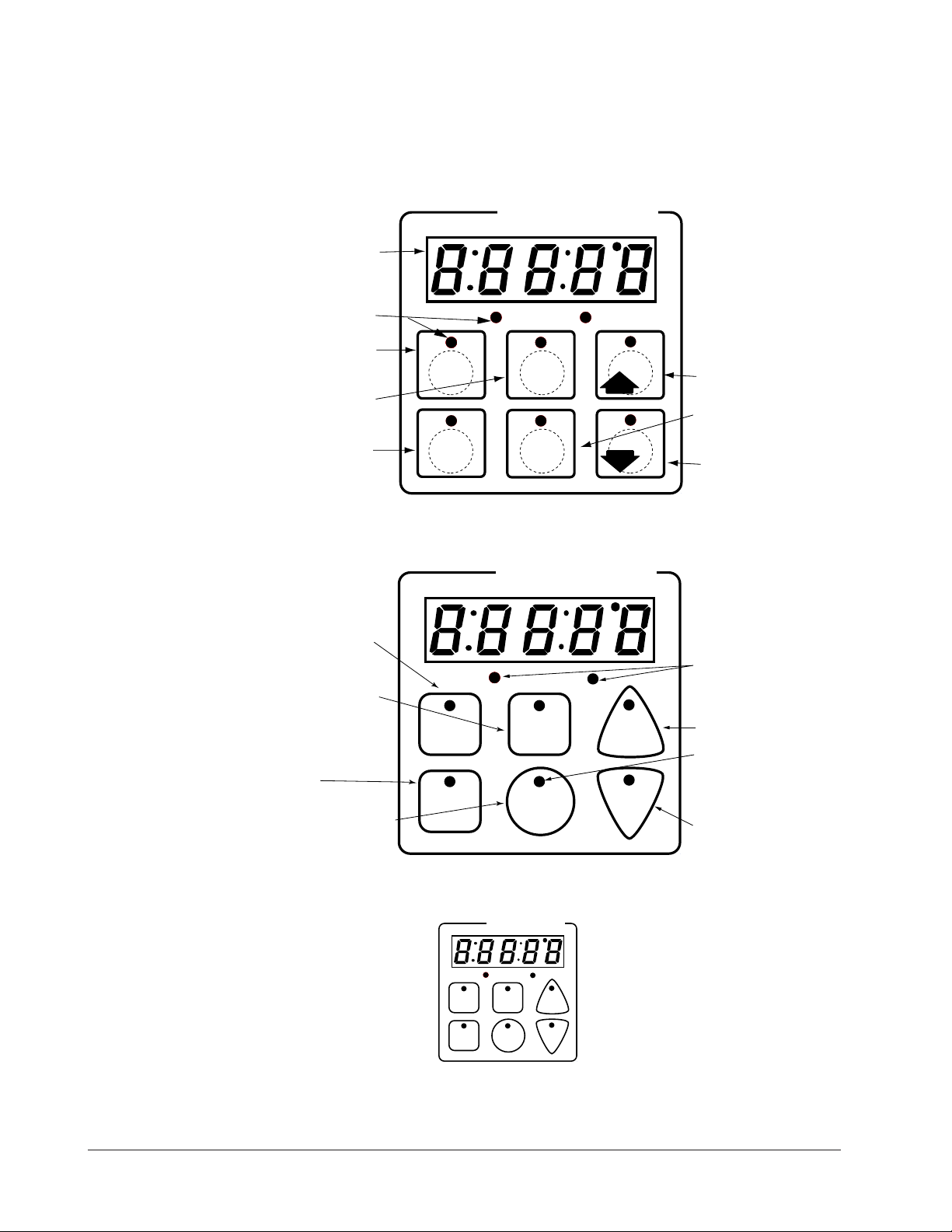
Up
Temp Set or display
temperature. Lights flash
rapidly if editing
parameters during menu
operation.
Time Set Time. Lights
flash rapidly if editing
parameters during menu
operation.
Not Used
Start/Stop Activate, pause
or cancel active menu.
Heat Indicator Light
Lit when heat output is on.
Increment
Start/Stop Indicator Light
Slow flash...Preheating
Rapid flash...Ready
Lit...Cooking
Off...Done
Decrement
AB
DE
GH
Enter
EscapeHome
Edit
C
F
MINICHEF 2000
Display five-digit, sevensegment numeric LED
display.
Indicator lights
(1 for each key, 2 for heat
channels).
Edit key (A) Access the
next level of parameters or
values.
Enter key (B) Enter the
value and return to
previous level.
Home key (D) Move to
Operation Mode with a
two-second key press.
Up key (C) Move up the
lists.
Escape key (E) Return to
original value when editing
a parameter value.
Down key (F) Move down
the lists.
Key Functions in Operation Mode
Summary of Input/Output Functions
Note: For details, see wiring instructions in the
32 ■ Watlow MINIC HEF 2000 Application 23
Hardware & Software Setup Guide
.
Page 34

Configuration Mode Quick Reference
These are the functions, parameters and values included in the Configuration Mode for
this application. You must select Application 23 to access them. For directions, see the
Hardware & Software Setup Guide. The Appendix of that guide includes an explanation
of all parameters and values.
Function Parameter Value Your Settings
{Etype} Equipment-Type [appl`] Application Number 1 - 28 23
[a_Loc] Application Number Yes, No
Security Lock
[t`OUt] Timer Output No, Yes
[SEtUP] Setup [`Ç_Ï`] Temperature Display Format °C or °F
[time] Time Display Format MMM:SS, HH:MM, H:MM:SS
(H=Hours, M=Minutes, S=Seconds)
[Chirp] Key Chirp On, Off
[tc```] Thermocouple Type J, K (shown as [````H]), E
[rtd``] RTD Curve DIN, JIS
[tconp] WatCurveTMTemperature On, Off
Compensation
[Ofst1] Temperature Offset, Channel 1 -99 to 99°F (-55 to 55°C)
[tr`lo] Temperature Range Low 0ºF (-18ºC) for rtd inputs,
32ºF (0ºC) for tc inputs to [tr`Hi]
[tr`Hi] Temperature Range High [tr`lo] to 1200ºF (649ºC)
[ready] Preheat Ready Feature Yes, No
[rband] Ready Band 1 to 1200°F (649°C)
[Cloc`] Real Time Clock Display Yes, No
[plOSS] Power Loss Menu Resume Yes, No
[al``1] Alarms for channel 1 None, Dev, Proc, Both
[aL`P1] Absolute Process Alarm 1 100 to 1200°F (38 to 649°C)
[aLdL1] Low Deviation Alarm 1 -999 to 0°F (-555 to 0°C)
[aLdH1] High Deviation Alarm 1 0 to 999°F (0 to 555°C)
[tHErl] Thermal [tyPE`] Temperature Control Type PID, On-Off
[HYSt1] Hysteresis 1 1 to 99°F (1 to 55°C)
[Pid`U] PID Units SI, US
[tune1] Auto-tuning 1 on, OFF
[ProP1] Proportional Band 1 1 to 999°F (1 to 555°C)
[rSEt1] Reset (integral) Gain 1 0.00 to 9.99 repeats/minute
[int`1] Integral Gain 1 0.00 to 99.99 minutes/repeat
[rAtE1] Rate (derivative) Gain 1 0.00 to 9.99 minutes
[dEr`1] Derivative Gain 1 0.00 to 9.99 minutes
[CYcL1] PID Cycle Time 1 1 to 60 seconds
`diag] WatHelp Used for equipment troubleshooting and testing. Not used when programming. See the Hardware
Diagnostics & Software Setup Guide.
Application 23 Watlow MINICHEF 2000 ■ 33
Page 35

Auto-tuning Note:
Before auto-tuning Application 23, [teNp1] in the operations menu must first be set to
a value that is typical of your application (See the Hardware & Software Setup Guide
for information on programming menus.). Then set [tHerl] / [tunE1] to [```on].
After you accept [```on], by pressing “Enter,” the controller will display [`tunE]
while auto-tuning is taking place.
The controller will cancel the auto-tuning process if it cannot be completed in 80 minutes. You can cancel the auto-tuning process at any time by pressing either key C or key
D and accepting [``Off], by pressing “Enter,” when it appears.
34 ■ Watlow MINIC HEF 2000 Application 23
Page 36

Step 7 Design a Faceplate Overlay
AB
DE
GH
Enter
EscapeHome
Edit
C
F
MINICHEF 2000
Heat
1
Cook
Temp(s)
2
Cook
Time(s)
4
5
6
Down
Your Company Logo
Start/
Stop
3
Up
Heat
To complete the installation, you must apply a graphic membrane to the front panel of
the controller. The following artwork will help you design and create a membrane for
this application. For more dimensions and guidelines, see the Hardware & Software
Setup Guide.
Suggested End-user Overlay:
This Prototyping and Training Membrane Overlay will help you with the configuration and programming steps. To order it, see the Ordering Information
at the back of this guide.
Application 23 Watlow MINICHEF 2000 ■ 35
Page 37

Step 8 Operate the Controller
DECF
MINICHEF 2000
[tENP1]
Edit Accept
Back-UpExit
DECF
MINICHEF 2000
[650°f]
Edit Accept
Back-UpExit
AB
GH
AB
GH
DECF
MINICHEF 2000
[`idle]
Edit Accept
Back-UpExit
AB
GH
[500°F]
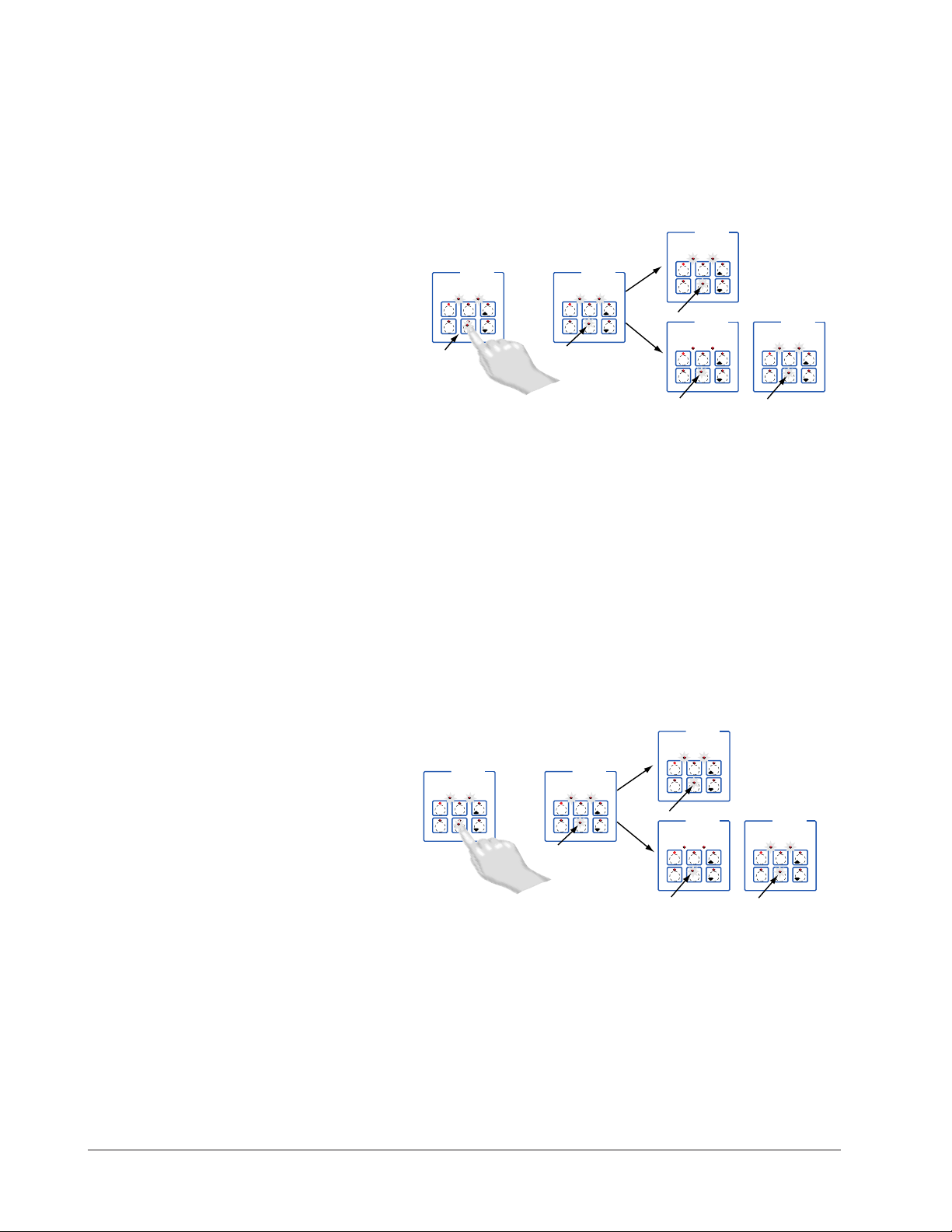
Summary of Key Functions in Operation Mode
Key Operation Function
A Cook Temp
B Cook Time
C Up (Increment)
D Not Used
E Start/Stop
F Down (Decrement)
Startup
Apply power to the griddle.
[`iDle] will appear on the display.
If the Real-time Clock option is installed and [SetUp] /[CLoc`] = [``YES] the pre-
sent time of day will appear on the display.
Set the Menu
Set the cooking temperatures.
1. Press the Cook Temp key for [teNp1] and then the cooking temperature value will
appear on the display.
2. Press the Up-arrow or Down-arrow key until the value you want appears on the display.
3 Press the Cook Temp key again.
The cooking temperature has been set.
[`idle] will appear on the display.
Set the cooking time.
1. Press the Cook Time key [tinE1] and then the cooking time value will appear on
the display.
2. Press the Up-arrow or Down-arrow key until the value you want appears on the display.
36 ■ Watlow MINIC HEF 2000 Application 23
Page 38

3. Press the Cook Time key again.
AB
DECF
GH
MINICHEF 2000
[`idle]
Edit Accept
Back-UpExit
SLOW
FLASH
AT OPERATING TEMPERATURE
(PREHEAT CONDITION MET)
RAPID
FLASH
B
DECF
MINICHEF 2000
[100f`]
Edit Accept
Back-UpExit
B
DECF
MINICHEF 2000
[ready]
Edit Accept
Back-UpExit
G H GH
A A
[pre-`] [`Heat]
The cooking time has been set.
[`idle] will appear on the display.
Five Second Timeout
When using the up or down keys to change a value, if you do not press any key for 5
seconds, the controller will automatically be set to the last value on the display and
return to [`idle].
Preheat
If the [Ready] parameter under the [SetUp] function in the Configuration mode is set
to [``yes], the controller will detect temperatures and preheat to operating temperature (above set point minus the ready band).
Note: The controller will not respond if Time1 is set to 0.
The menu you have chosen becomes the current menu for controller operation. Until
the menu is completed or canceled , the indicator light above the Start/Stop key will
light up (flashing or steady).
• If the griddle is not at operating temperature, it will preheat. Meanwhile:
The word [Pre-`] [`Heat] will appear on the display for a few moments.
The menu key indicator light will flash slowly.
The temperature of Channel 1 will be displayed until the operating temperature for
both channels is reached.
The heat output indicator light (G, just below the display) will light up whenever
the controller is calling for heat.
When the channel is at operating temperature (set points minus the ready band)
[ready] will appear on the display and the Start/Stop key indicator light will flash
rapidly. You are now ready to cook.
• If the griddle is at operating temperature, the display goes directly to [Ready]
without indicating preheat or temperature.
Run a Menu (with preheat feature)
This procedure describes how to run the menu when the preheat feature is active (when
the [Ready] parameter in the [SetUp] function of the Configuration Mode is set to
[```Yes]).
1. Set the menu as shown earlier.
2. With [`idle] or time of day on the display, press the Start/Stop key.
If the preheat condition (temperatures >= set point minus the ready band) has not
been met, the griddle will preheat until [ready] appears on the display.
If the griddle is at operating temperature [ready] will appear on the display.
Application 23 Watlow MINICHEF 2000 ■ 37
Page 39

3. With [ready] on the display, place the food on the griddle and press the Start/Stop
DECF
MINICHEF 2000
[`idle]
Edit Accept
Back-UpExit
DECF
MINICHEF 2000
[`0009]
Edit Accept
Back-UpExit
B
DECF
MINICHEF 2000
[`idle]
Edit Accept
Back-UpExit
G H
A
AB
GH
AB
GH
STEADY
ON
SLOW
FLASH
DECF
MINICHEF 2000
[``EnD]
Edit Accept
Back-UpExit
B
DECF
MINICHEF 2000
[`idle]
Edit Accept
Back-UpExit
G H
AAB
GH
RAPID FLASH
SLOW FLASH
DECF
MINICHEF 2000
[ready]
Edit Accept
Back-UpExit
DECF
MINICHEF 2000
[`0009]
Edit Accept
Back-UpExit
B
DECF
MINICHEF 2000
[`idle]
Edit Accept
Back-UpExit
G H
A
AB
GH
AB
GH
STEADY
ON
RAPID
FLASH
SLOW
FLASH
DECF
MINICHEF 2000
[``EnD]
Edit Accept
Back-UpExit
B
DECF
MINICHEF 2000
[`idle]
Edit Accept
Back-UpExit
G H
AAB
GH
RAPID FLASH
SLOW FLASH
key(indicated by the rapidly flashing indicator light).
The Start/Stop indicator light will light up. Time will count down on the display.
4. When the cooking cycle is finished, the controller goes into idle and the Start/Stop
key indicator light will switch off. The controller will continue to regulate to the setpoint.
5. Remove the food from the griddle.
6. To repeat cooking, repeat steps 2 through 5.
Run a Menu (without preheat feature)
This procedure describes how to run the menu when the preheat feature is inactive
(when the [Ready] parameter in the [SetUp] function of the Configuration Mode is set
to [```no]).
1. Set the menu as shown earlier.
2. With [`idle] or time of day on the display, press the Start/Stop key.
3. The Start/Stop indicator light will light up. Time will count down on the display.
4. When the cooking cycle is finished, the controller goes into idle and the Start/Stop
key indicator light will switch off. The controller will continue to regulate to the setpoint.
5. Remove the food from the griddle.
6. To repeat cooking, repeat steps 2 through 5.
Adjust a Menu While Cooking
You can adjust the temperature and time settings during the cooking and hold
sequences by performing the actions shown under “Set the Menu” earlier in this section.
38 ■ Watlow MINIC HEF 2000 Application 23
Page 40

Changes can be made to temperature and time only during the portion of the cooking
sequence in which they are active. For example: a change to the first cooking temperature [tENP1] can be made only when the first cooking temperature is being run during
the cooking sequence.
Temperature changes made while cooking are saved and become part of the permanent
menu. Time changes are not saved and do not become part of the permanent menu.
Cancel a Menu
Canceling a menu stops controller operation completely. The controller does not maintain set point temperatures or run time. You cancel a menu to run another menu, stop
menu operation for any reason, or are preparing to shut off the griddle.
• Press the Start/Stop for 2 seconds.
Heat outputs will switch off. The heat output indicator light will switch off.
[`idle] or the time of day will be on display.
Change Menus or Restart
1. If the controller is preheating or running a menu, cancel the menu by pressing and
holding the Start/Stop for 2 seconds. If the controller is in [`idle] go to 2.
2. Press the key for the menu you want to run.
Based on its programming, the unit will run the menu in one of the ways described
earlier.
Timer Output
If [Etype]] / [T`OUt]] in the Configuration Mode is set to [``yes], when time is counting down Event Output 2 is on. It is off during [Pause], [`Idle] or [Hold].
Temperature Alarms
The controller will alert you to temperature alarm conditions if they occur. If an alarm
occurs, take action as determined by your supervisor. See the Appendix in the Hardware
& Software Setup Guide for Troubleshooting Chart and a summary of temperature
alarms.
Errors
The controller will alert you to errors if they occur. Errors are critical problems that
shut down the unit. If an error occurs, an error message will appear on the display. You
should switch off the power and call for service.
See the Appendix in the Hardware & Software Setup Guide for a Troubleshooting Chart
and a summary of errors.
Application 23 Watlow MINICHEF 2000 ■ 39
Page 41

Specifications (1032)
Control Mode
• Single and dual heat channels, PID or on/off.
• Microprocessor-based, programmable, reverse-acting
control outputs.
• User-selectable embedded application software defines
operation of display, keys, inputs, outputs, timing action.
• One-step auto-tuning, WatHelp diagnostics, WatCurve
temperature compensation.
Agency
• CE approved:
89/336/EEC Electromagnetic Compatibility Directive
-EN 50081-1: Emissions
-EN 50082-1: Immunity
73/23/EEC Low-Voltage Directive
-EN 60730-1 and EN 60730-2-9: Safety
• NSF Listed, Criteria 2.
5
• AGA: UL tested to AGA standard Z21.23, UL File
#E43684.
• UL and C-UL recognized, UL 197, 873, 991 and CSA
standard C22.2-24, File # E43684.
Operator Interface
• Membrane overlay, contamination and water resistant,
(supplied by customer).
• LED display, 5-digit, 0.56 in high, red.
• Displays times, temperatures, user prompts and
diagnostic codes.
• User-selectable time and temperature display formats.
• Temperature display formats
—˚F or ˚C.
• Time display formats—H:MM:SS, HH:MM, or MMM:SS.
• 8 discrete indicator LEDs, red.
• 6 tactile feedback keys.
• Menu-driven operation and manual modes available.
• WatHelp diagnostics.
• Real-time clock option displays time of day.
Accuracy
• Calibration accuracy and sensor conformity
for Type J thermocouple and RTD, ± 0.35% of span for
Type K and E thermocouples, ±1 LSD, 77°F ± 5°F
ambient and rated line voltage of ±10%.
• Accuracy span: 1000°F (540°C) minimum.
• Temperature stability: ± 0.15˚F/˚F (0.15˚C/˚C) change
in ambient typical.
Sensors/Inputs
• Contact inputs, TTL compatible with internal pull-up
resistor, two available.
• Thermocouple,
3
software selectable Type J, K or E,
32 to 1200°F. (Dual-channel applications require at least
one ungrounded thermocouple).
3
•RTD,
2- or 3-wire, platinum, 100, 500, 1000Ω, at 0°C,
software selectable DIN or JIS curves, 0 to 1200°F
(3-wire will function as 2-wire).
• Input A /D resolution: 15 bit.
Output Options
• Solid-state relay, 0.4A, with or without contact suppression.
• Switched dc signal, 4.5V to 5.25V, 30mAmaximum
output, minimum load resistance > 150Ω, non-isolated.
1
2
: ± 2.0°F
Audible Output Options
• Switched dc signal, 4.5V to 5.25V, 30mAmaximum
output, minimum load resistance > 150Ω, non-isolated.
• Internal audible alarm, 75dB at 10 cm.
Connectors
• Sensor Input Terminal Strip
quick-connect.
• Power Supply & Input/Output Terminal
4
: RIACON, 6-position,
4
: AMP,
15-position, quick-connect.
Power/Line Voltage
• 20.4 to 26.4VÅ (ac), 47 to 63Hz.
• 15VA maximum.
• For CE applications, input power must be limited to
15W external to the control.
• Program retention upon power failure via non-volatile
memory.
• Battery/real-time clock option: 6-year lithium battery,
provides power backup upon power failure, operation
resumption after power recovery, ability to display time
of day.
Operating Environment
• 32 to 176°F (0 to 80°C), 0 to 90% RH, non-condensing.
Storage Temperature
• -40 to 176°F (-40 to 80°C).
Mechanical
• Case: polycarbonate Lexan with adjustable mounting
collar (vertical or horizontal orientation), designed for
mounting on 16-, 18-, 20- and 22-gauge panels.
• Internal panel mounting requires a specified panel
cutout and four #6-32 studs or equivalent.
• Overall width x height x depth: horizontal - 4.13 in x
3.25 in x 2.00 in; vertical - 3.25 in x 4.13 in x 2.00 in
(Assumes mating connectors are attached. Does not
include wire bundle space requirements.).
• Vibration: 2g, 10 to 150Hz, applied in any one of three
axes.
• Weight: 6.50oz maximum.
Program Storage
• All non-embedded user and factory programs are
stored in non-volatile memory. Can be changed by
reprogramming.
Sample/Update Rates
• 1 input: 4Hz.
• 2 inputs: 4Hz.
• PID: 1Hz.
• Control outputs: 100Hz.
• Display: 10Hz.
1
The MINICHEF 2000 controller is to be used in systems with an
external high temperature limiting device.
2
Thermocouple lead resistance of 200Ω causes < 1°C error. RTD, 22
gauge wire will not contribute more than 0.086°F error /ft.
3
Dual channel applications require either two thermocouple sensors or two identical RTD sensor types.
4
For mating connector information, see Ordering Information
Accessory section.
5
Certified for thermometer accuracy (oven and hot food holding
applications from 32°F to 60°F) when used with RTD or type J thermo
couple probes.
40 ■ Watlow MINIC HEF 2000 Specifications
Page 42

Ordering Information
(1033)
F 2 H A - _ _ _ 1 - _ _ A A
M
INICHEF™ 2000
Cooking controller with numerous food
equipment application software sets,
single and dual channel on/off or PID
temperature regulation, timer and
machine-function control, microprocessorbased, programmable, auto-tuning,
WatCurve, WatHelp diagnostics,
24V
Å
(ac) power input, agency approved,
flush mounted (membrane faceplate
supplied by customer).
Inputs
1 = Dual thermocouple, Type J, K or E
2 = Dual RTD, platinum, 100Ω, curve
selectable
3 = Dual RTD, platinum, 500Ω, curve
selectable
4 = Dual RTD, platinum, 1000Ω, curve
selectable
Note: All models include two event inputs,
switched dc logic signal, non-isolated.
Output Number 1
1 = Switched dc, 5V nominal, 30mA,
non-isolated
2 = Solid-state relay, Form A, 0.4A,
without RC suppression
3 = Solid-state relay, Form A, 0.4A,
with RC suppression
Output Number 2
1 = Switched dc, 5V nominal, 30mA,
non-isolated
2 = Solid-state relay, Form A, 0.4A,
without RC suppression
3 = Solid-state relay, Form A, 0.4A,
with RC suppression
Event Outputs 1 and 2
1 = 2 event outputs, switched dc, 5V nominal,
30mA, non-isolated
Battery and Real-time Clock
0 = None
1 = Includes battery and real-time clock
Audible Alarm
0 = Alarm signal available at connector,
switched dc, 5V nominal, 30mA, non-isolated
1 = Internal alarm included
Software
AA = Standard Food Equipment Application
Software Set
XX =
Custom Set-up parameters or Made-To-Order
custom
Sales Engineer. Code number assigned by factory.
software. Consult your local Watlow
Ordering Information Watlow MINIC HEF 2000 ■ 41
Page 43

Ordering Information: Part Numbers & Accessories
MINICHEF 2000 Accessories
0836-0442-0000 Sensor Input Mating Connector,
(RIACON #31007106), 6-position,
quick-connect terminal, screw
connection for 28-14 AWG wires,
tighten to 7in/lb
A001-0298-0000 Power Supply and I /O Mating
Connector Kit. Includes:
– 1 AMP #1-640523-0, 15-position,
quick-connect terminal
– 15 AMP #641300-1 crimp pins
0238-0679-0000
0830-0479-0000 Prototyping EPROM Extraction Tool,
A001-0249-0001 120VÅ to 24VÅ (ac), stepdown
A001-0249-0002 208 /240VÅ to 24VÅ (ac), step-
Prototyping & Training Membrane
Overlay, adhesive-backed,
4.75 in x 4.75 in
AMP #821980-1
transformer, class 2, quick-connect
terminals included
down transformer, class 2, quickconnect terminals included
Recommended Sources of Supply
for Miscellaneous Items
DURA-TECH, Inc. •
LaCrosse, WI
(608) 781-2570
Custom Membrane Faceplates
MINICHEF 2000 Documentation
WMC2-XUGN-0000 The Complete
2000 User Guide
WMC2-XADN-0000 The Complete
2000 User Guide on CD
M
WMC2-XTDN-0000
WMC2-XSGN-0000 Hardware & Software
WMC2-XAGN-0001 Cook & Hold Oven
WMC2-XAGN-0002 Convection Oven
WMC2-XAGN-0003 Deepfat Fryer Application
WMC2-XAGN-0004 Griddle Application Guide
WMC2-XAGN-0005 T imer Application Guide
WMC2-XAGN-0006 Shelf-T imer Application
WMC2-XAGN-0007 Rotisserie Oven
INICHEF
Disk
Setup Guide
Application Guide
Application Guide
Guide
Guide
Application Guide
M
INICHEF
M
INICHEF
2000 Tutorial
AMP, Inc. •
Harrisburg, PA
1-800-522-6752
RIA Electronic, Inc.
Eatontown, NJ
(908) 389-1300
Prototyping EPROM Extraction
Tool
Part No. 821980-1
•
Pin Crimping Hand Tools
Part No. 90325-1 or 58514-1
•
Pin Extraction Hand Tool
Part No. 455822-2
•
RIACON Connectors
42 ■ Watlow MINIC HEF 2000 Ordering Information
Page 44

Watlow Controls
Watlow Controls is a division of Watlow Electric Mfg. Co., St. Louis, Missouri, a manufacturer of industrial electric heating products since 1922. Watlow begins with a full set
of specifications and completes an industrial product that is manufactured totally inhouse, in the U.S.A. Watlow products include electric heaters, sensors, controls and
switching devices. The Winona operation has been designing solid state electronic control devices since 1962, and has earned the reputation as an excellent supplier to original equipment manufacturers. These OEMs depend upon Watlow Controls to provide
compatibly engineered controls that they can incorporate into their products with confidence. Watlow Controls resides in a 100,000-square-foot marketing, engineering and
manufacturing facility in Winona, Minnesota.
Technical Assistance
If you encounter a problem with your Watlow controller, refer to the Troubleshooting
Chart in this guide. Also review all of your configuration information for each step of
the setup to verify that your selections are consistent with your applications.
If the problem persists after checking all the steps, you can get technical assistance by
calling Watlow Controls at (507) 454-5300, between 7 a.m. and 5 p.m. CST, and asking
for an applications engineer. When you call have the following information on hand: the
controller’s part number, date code, serial number, software revision number, and application number. Much of this information is available on the controller case. All of this
information is also available via the MINICHEF 2000 main display by accessing the
WatHelp Diagnostics Function under [`diag] in the Configuration Mode.
We Value Your Feedback
Your comments and suggestions on this manual are welcome. Please send them to,
Technical Writer, Watlow Controls, 1241 Bundy Blvd., P.O. Box 5580, Winona, MN
55987-5580 or call (507) 454-5300 or fax (507) 452-4507.
Contact
• Phone: (507) 454-5300.
• Fax: (507) 452-4507.
• For technical support, ask for an Applications Engineer.
• To place an order, ask for Customer Service.
• To discuss a custom option, ask for the MINICHEF 2000 Product Manager.
Warranty
The MINICHEF 2000 is warranted to be free of defects in material and workmanship for
36 months after delivery to the first purchaser for use, providing that the unit has not
been misapplied. Since Watlow has no control over its use, or misuse, we cannot guarantee against failure. Watlow's obligations hereunder, at Watlow's option, are limited to
replacement or refund of purchase price of a unit which upon examination proves to be
defective within the warranty period. This warranty does not apply to damage resulting
from transportation, alteration, misuse, or abuse.
Returns
• Call or fax Customer Service for a Return Material Authorization (RMA) number
before returning a control.
• Put the RMA number on the shipping label, and also on a description of the problem.
• 20% of net price restocking charge applies to all standard units returned to stock.
Note: All documentation of the MINICHEF 2000 is subject to change without notice.
Warranty and Returns Watlow MINICHEF 2000 ■ 43
Page 45

Notes
44 ■ Watlow MINIC HEF 2000 Application 23
Page 46

Watlow MINICHEF™ 2000 Griddle Applications Guide
Watlow Controls, 1241 Bundy Blvd., P.O. Box 5580, Winona, MN U.S.A. 55987-5580 Phone: (507) 454-5300, Fax: (507) 452-4507
 Loading...