

Page 1
W A T L O W
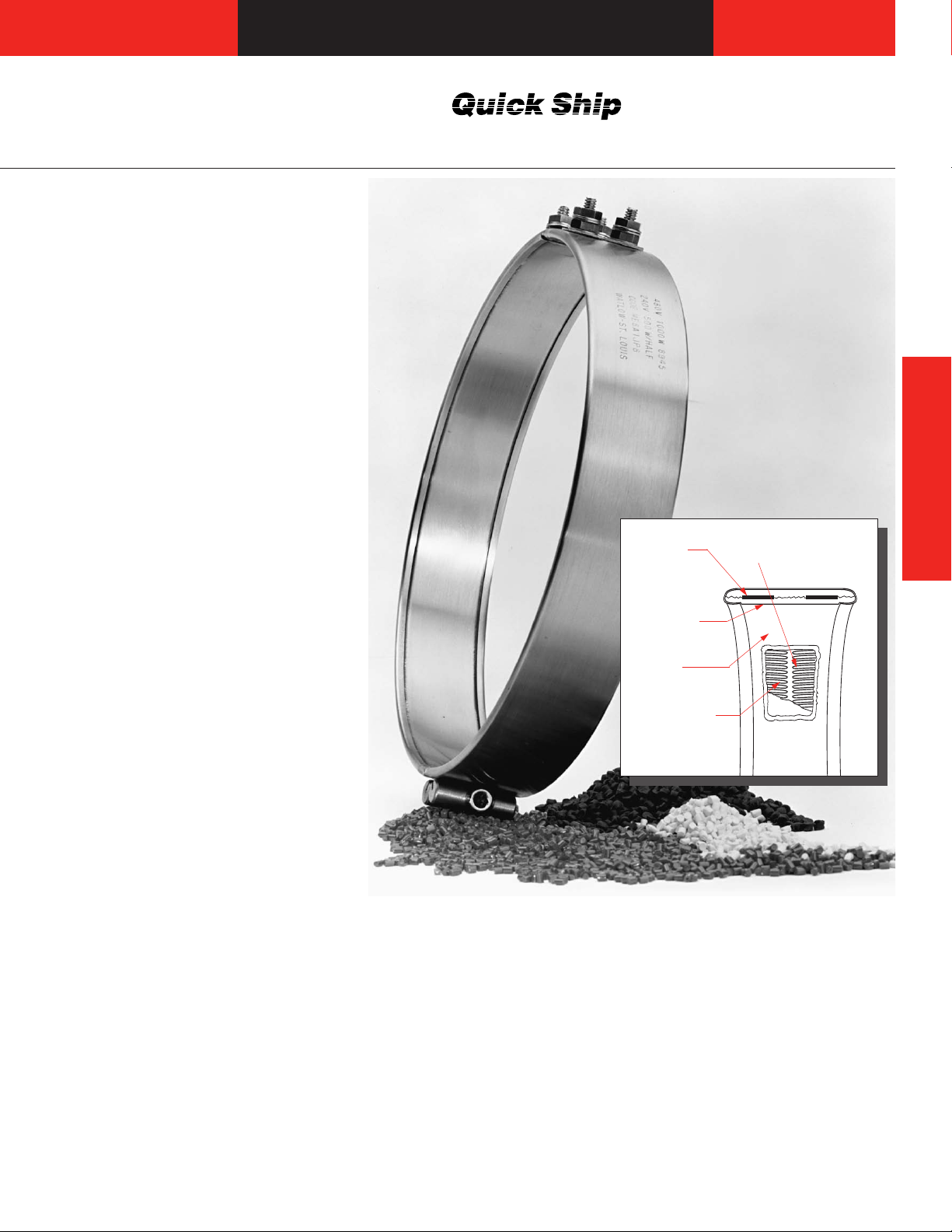
Band Heaters
MI Barrel and Nozzle
The MI band is a high performance
heater. Its performance and name
are derived from Watlow’s exclusive
mineral insulation—a material that
has much higher thermal
conductivity than the mica and
hard ceramic insulators used in
conventional heaters.
A thin layer of the “high” thermal
conductive MI material is used to
electrically insulate the element wire
from the inside diameter of the
heater sheath. A thicker, “low”
thermal conductivity layer backs up
the element wire, directing the heat
inward toward the part that is being
heated. The result is more efficient
heat transfer—a performance
solution that lowers element wire
temperatures and increases
heater life.
Performance Capabilities
• Heater operating temperatures to
760°C (1400°F)
• Watt densities to 230 W/in
(35.6 W/cm2) available on
small diameter nozzle bands
• Watt densities to 100 W/in
(15.5 W/cm2) available on large
diameter barrel bands
Features and Benefits
Operating temperatures to
F)
760
C (1400
°
°
• Safely melts resins such as
Peek®, Teflon®, Ultem®and
®
Zytel
Higher watt densities
Contributes faster heat-up and
•
through-put for increased
productivity
High thermal conductivity of MI
and low mass construction
Gives an almost instant r
•
to temperature control
Eliminates ther
•
mal lag and
temperature overshoot associated
with ceramic knuckle heaters
2
2
esponse
Stainless steel co
old design
f
ver and side
• Resists contamination by
ow of plastic or other
overfl
owing materials
ee-fl
fr
Side folds tur
•
n to the inside
diameter rather than the outside
diameter
lamp bar
ermanentl
P
y attac
hed c
• Eliminates cumbersome
clamping straps, which make
installation easier
Same day shipment on all stock heaters with post
•
erminals or Type B leads.
t
Thick Low
Conductivity
MI Backing
Thin High
Conductivity
MI Insulation
Stainless
Steel Sheath
Element Wire in
Mineral Insulation
Coiled or Sinuated
Wire Element
Applications
Extruders
•
• Blown film dies
• Injection molding machines
Other cylinder heating
•
applications
s
®
on
efl
T
and Zytel®ar
of E.I. du Pont de Nemours & Company
®
Ultem
is a registered trademark of General
Electric Corporation.
®
is a registered trademark of Greene,
Peek
Tweed & Company.
egistered trademarks
e r
Band Heaters
.
1
Page 2

Band Heaters
MI Barrel and Nozzle
Applications and Technical Data
The
Physical Limitations of
Variations
table shows you the
availability of widths, inside
diameters and terminations for
Watlow’s MI band heaters. To make
sure the available terminations will
meet your application needs, refer
Physical Limitations of Variations
Widths I.D. Available—in. (mm)
in. (mm) 1 pc. Construction Expandable 2 pc. Construction Available Terminations
Minimum Maximum Minimum Maximum Minimum Maximum
in. (mm) in. (mm) in. (mm) in. (mm) in. (mm) in. (mm)
1 (25.4) 1 (25.4) – 14 (355.6) 3 (76.2) – 14 (355.6) 3 (76.2) – 14 (255.6) All
3
⁄8 (34.9) 1 (25.4) – 3 (76.2) 3 (76.2) – 6 (152.4) 3 (76.2) – 6 (152.4) All
1
11⁄2 (38.1) 1 (25.4) – 14 (355.6) 3 (76.2) – 14 (355.6) 3 (76.2) – 28 (711.2) All
2 (50.8) 11⁄4 (31.8) – 14 (355.6) 3 (76.2) – 14 (355.6) 3 (76.2) – 28 (711.2) All
1
⁄2 (63.5) 11⁄4 (31.8) – 14 (355.6) 3 (76.2) – 14 (355.6) 3 (76.2) – 28 (711.2) All
2
3 (76.2) 11⁄4 (31.8) – 14 (355.6) 3 (76.2) – 14 (355.6) 3 (76.2) – 28 (711.2) All
31⁄2 (88.9) 13⁄4 (44.5) – 14 (355.6) 3 (76.2) – 14 (355.6) 3 (76.2) – 28 (711.2) All - Except 90° “B” Leads
4 (101.6) 2 (50.8) – 14 (355.6) 3 (76.2) – 14 (355.6) 3 (76.2) – 28 (711.2) All
1
⁄2 (114.3) 21⁄4 (57.2) – 14 (355.6) 3 (76.2) – 14 (355.6) 3 (76.2) – 28 (711.2) All
4
5 (127.0) 2
51⁄2 (139.7) 23⁄4 (69.85) – 14 (355.6) 3 (76.2) – 14 (355.6) 4 (101.6) – 28 (711.2) Post Terminals, SLE
6 (152.4) 3 (76.2) – 14 (355.6) 3 (76.2) – 14 (355.6) 4 (101.6) – 28 (711.2) All
7 (177.8) 4 (101.6) – 14 (355.6) Post Terminals, SLE
1
⁄2 (63.5) – 14 (355.6) 3 (76.2) – 14 (355.6) 4 (101.6) – 28 (711.2) All - Except 90° “B” Leads
N/A
N/A
N/A
to the illustrations of termination
variations in this section.
If you need to exceed limitations
shown, contact your Watlow sales
engineer or authorized distributor.
N/A
General Limitations:
• Maximum width of 1 inch (25 mm)
diameter heater is 1.5 inches wide
(38 mm).
Maximum heater width = 2x heater
•
diameter
Minimum I.D. for T
•
ype B, C, E and H
leads = 1 inch (25 mm)
• Minimum I.D. for Type B
—
90 degree
leads = 11⁄8 inches (28 mm)
• Maximum lead amps: 12.5A per pair
• Maximum amps (post terminals): 30A
per pair
• Minimum diameter and width for SLE
is 4 inches x 11⁄2 inch width
SLE maximum 17.0 amps
•
90 degr
•
250V
ee bends not available over
Å(ac)
Standard Gaps:
•≤3 inches = 1⁄8 inch nominal
• 3 inches ≤6 inches = 1⁄4 inch
nominal ±1⁄8 inch
• 6 inches ≤14 inches = 3⁄8 inch
nominal ±1⁄8 inch
• >14 inches = 1⁄2 inch nominal
±1⁄4 inch
2
Page 3
W A T L O W
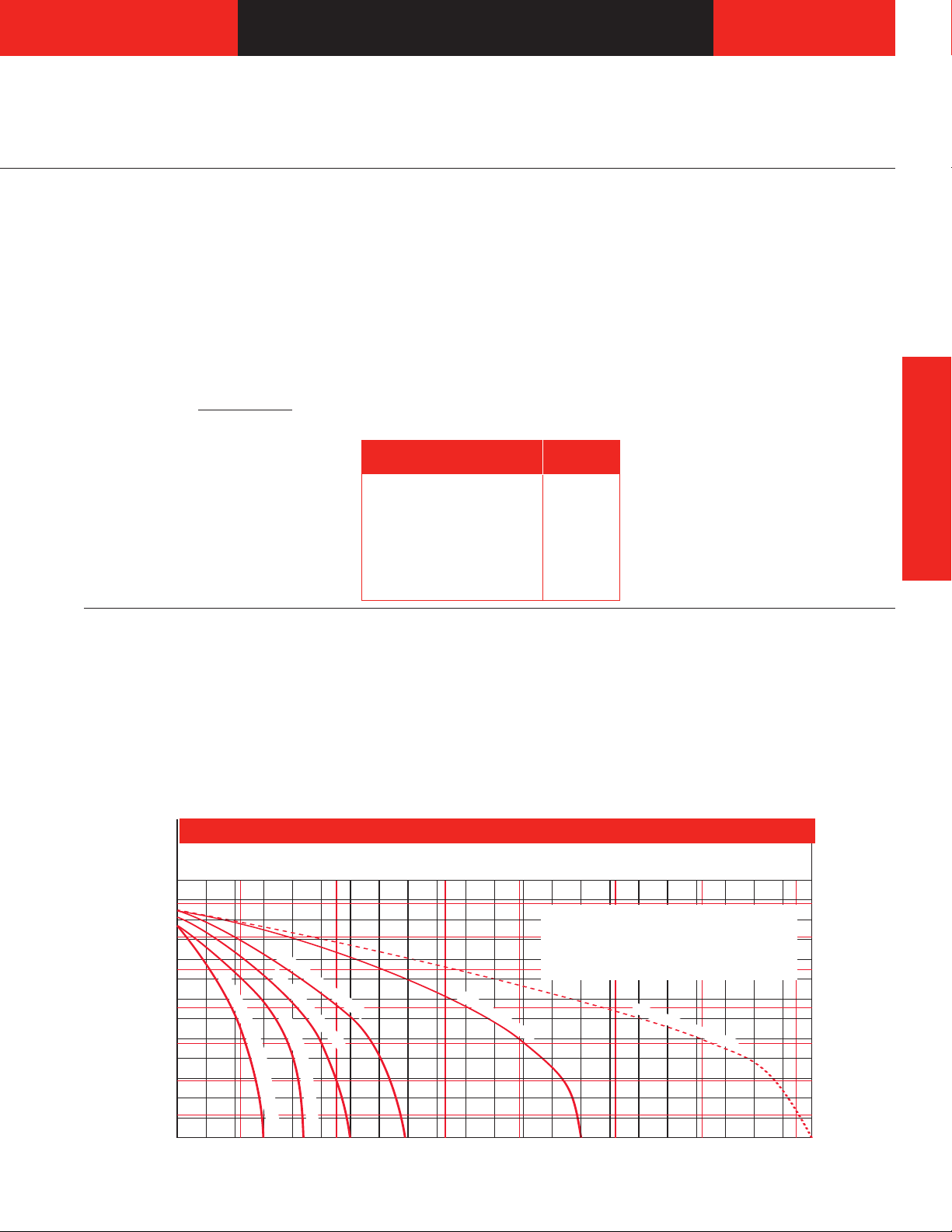
100
Watt Density–W/in
2
Part Temperature–°C
200
300
400
500
600
1300
200
1200
1100
1000
900
800
700
600
500
400
300
10 20 30 40 50 60 70 80 90 100 110 120 130 140 150 160 170 180 190 200 210 220 230
700
Part Temperature–°F
5 10 15 20 25 30 35
Watt Density–W/cm
2
1
1
/
2
in. (38.1 mm) I.D.
3 in. (76.2 mm) I.D.
6 in. (152.4 mm) I.D.
10 in. (254 mm) I.D.
1
4
i
n
.
(
3
5
5
.
6
m
m
)
I
.
D
.
&
2
P
i
e
c
e
1
2
i
n
.
(
3
0
4
.
8
m
m
m
)
I
.
D
.
Band Heaters
MI Barrel and Nozzle
Applications and
Technical Data
Calculating Watt Density
Watt density is the amount of
wattage per square inch of heated
area. To determine watt density,
divide the total wattage by the
heated area.
Watt Density =
To apply this equation, we must
define the term "heated area."
Total Watts
Heated Area
Heated area is the total contact
surface of the heater less areas of
no-heat that are found around
terminals, mounting holes, etc.
Heated Area =
Total Contact Area - No-Heat Area
To calculate the heated area:
1.Locate the no-heat factor from
the chart below that corresponds
Type Factor
in.
1 pc. lead unit Type B, C,
H, E or 90°B 1.37
1 pc. post terminal 1.60
1 pc. expandable post term 3.18
1 pc. expandable lead unit 3.00
True 2 pc. post term 3.20
True 2 pc. leads 2.74
SLE 3.68
to the type of heater being
considered.
2.To use the formula below, insert
the no-heat factors, diameter and
width (in inches).
Heated Area =
(3.14 x Diameter - No-Heat
Factor) x Width
Band Heaters
Maximum Allowable Watt Density
The following derating factors apply
to the
Maximum Allowable Watt
Density
chart, which are shown in
both inch base and metric for your
convenience. Please review these
factors and the chart to determine
the correct watt density curve for
your application.
Derating Factors:
• For units over two inches
(51 mm) in width, multiply watt
density by 0.80.
• In applications where unusual
operating conditions are present,
such as irregular mounting
surfaces, contact the Watlow
factory in St. Louis, Missouri,
for watt density limitations.
Maximum Allowable Watt Density
Allowable watt density for 11⁄2 in. wide
MI band heaters:
• Moderate cycling
• Heaters properly clamped
• Heaters mounted on a smooth cylinder
• For two-piece units used in
vertical applications, refer to
Clamping Matrix Application
Guide
.
• For applications where insulating
blankets are used, multiply W/in
(W/cm2) by 0.75.
2
3
Page 4

Band Heaters
80
75
70
65
60
55
50
45
40
35
30
25
20
15
10
0
4
1
2
Watt Density–W/in
2
Dia.
Width
8>10
10 >12
12 >14 14 >16
16 >18
18 >20
20 >22 22 >24
24 >26
26 >28
Above Recommended Watt Densities
Consult Engineering
1
1
2
"
to
4"
4
1
2
"
to
7"
1
1
2
"
to
4"
4
1
2
"
to
7"
1
1
2
"
to
4"
4
1
2
"
to
7"
1
1
2
"
to
4"
4
1
2
"
to
7"
1
1
2
"
to
4"
4
1
2
"
to
7"
1
1
2
"
to
4"
4
1
2
"
to
7"
1
1
2
"
to
4"
4
1
2
"
to
7"
1
1
2
"
to
4"
4
1
2
"
to
7"
1
1
2
"
to
4"
4
1
2
"
to
7"
1
1
2
"
t
o
4"
4
1
2
"
t
o
7"
B
B
B
B
A
A
A
A
B
A
C
A
DCDCD
C
DCDCD
D
C
B
D
C
D
C
D
C
D
C
D
C
DCD
C
MI Barrel and Nozzle
Applications and
Technical Data
MI Band Clamping Matrix Application Guide
• Review the
Watt Density
chart to
ensure the application does not
exceed the maximum watt
density at operating temperature
after applying derating factors.
• Locate clamping guideline for
unit diameter, width and watt
density.
• Description of guideline letters
are at the bottom of the
MI Band
Clamping Matrix Application
.
Guide
• Note: Upward arrows are up to
and not including specified watt
density. Downward arrows are
greater than or equal to specified
watt density.
Note: One inch wide heaters use welded barr
A
B
C
D
clamp bars.
=
=
=
=
Standar
Spring clamps, expandable or one piece construction
Spring clamps, at one gap, welded barr
Spring clamps, spring clamps at both gaps
d clamping, expandable or one piece construction
4
el nuts at other gap
≥ 5 in. (127 mm)
Width
≥ 3 in. (76.2 mm)
3 in. (76.2 mm)
<
Clamp P
oints at Eac
3
2
1
h Gap
el nuts rather than
Page 5

W A T L O W
0.36 in.
(9 mm)
0.16 in.
(4 mm)
1
2 in.
(
305 mm)
1.250 in.
(32 mm)
W
idth 0.0625 in.
(1.6 mm)
I.D.
0
.812 in.
(
21 mm)
termination types
(64A,B,C)
0.36 in.
(9 mm)
0.625 in.
(16 mm)
N
om.
0.75 in.
(19.05 mm) Nom.
0.656 in.
(16.70 mm) Dia.
0.557 in.
(14.10 mm)
0.191 in.
(4.90 mm)
I.D.
0.75 in.
(19 mm)
0.625 in.
(16 mm)
N
om.
0.16 in.
(
4 mm)
Width0.0625 in.
(1.6 mm)
I.D.
1.250 in.
(32 mm)
I
.D.
0
.16 in.
(
4 mm)
1.250 in.
(32 mm)
W
idth
0
.0625 in.
(
1.6 mm)
0.75 in.
(19.05 mm) Nom.
I.D.
0.191 in.
(4.90 mm)
0.656 in.
(16.70 mm) Dia.
0.635 in.
(16.10 mm)
0
.44 in.
(11.17 mm) Dia.
0.656 in.
(16.70 mm) Dia.
0.635 in.
(16.10 mm)
I.D.
0.191 in.
(4.90 mm)
0.75 in.
(19.05 mm) Dia.
0.656 in.
(16.70 mm) Dia.
0.635 in.
(16.10 mm)
0.191 in.
(4.90 mm)
I.D.
0.75 in.
(19.05 mm) Nom.
I.D.
0.656 in.
(16.70 mm) Dia.
0.557 in.
(14.10 mm)
0.191 in.
(4.90 mm)
0.75 in.
(19.05 mm) Nom.
12 in. (305 mm) Standard Type B
Lead Wire Length
25˚
Stainless Steel Sheath
R.375 in.
3 in.
(76.2 mm)
1
9
/
16
in.
(39.7 mm)
Band Heaters
MI Barrel and Nozzle
Termination Variations
Leads Type B, Type B—90 degree
Rotation,Type B—180 degree
Rotation or Type C: Two fiberglassinsulated lead wires exit in a single
metal braid for good abrasion
protection, lead flexibility and wiring
convenience. Leads are two inches
(51 mm) longer than braid. Shipped
with 12 inch (305 mm) leads, unless
longer length is specified. To order,
specify
Sealed Lead Option
Non-Stock
type and length.
Type B
Stock
Type B—90 Degree Rotation
Non-Stock
Type B—180 Degree Rotation
Stock
Band Heaters
Type C
Stock
Post Terminals
Stock
Post terminals provide optimum
connections. Screw thread is 10-24.
To order, specify post terminals
(metric threads available).
Type K
Stock
Type K: Flexible lead wires exit vertically from the heater. These leads
can be bent adjacent to the heater
for a quick and easy connection. To
order, specify Type K and length.
Type E
Stock
ype E: Loose metal braid encloses
T
two fiberglass leads for good
abrasion protection, lead flexibility
and wiring convenience. Leads ar
e
two inches (51 mm) longer than
braid. Shipped with 12 inch
(305 mm) leads, unless longer
length is specified. To order, specify
Type E and length.
Type H
Stock
Type F
Stock
ype F: Loose fi
T
berglass sleeving
encloses two fiberglass leads for
additional insulation pr
e high temperatur
wher
otection
e or minor
abrasion is present. Leads are two
inches (51 mm) longer than the
sleeving. T
o order, specify
ype F
T
and length.
ype H: A fl
T
exible steel hose
encloses the leads for maximum
abrasion pr
otection. Leads are two
inches (51 mm) longer than hose.
Shipped with 12 inch (305 mm)
leads, unless longer length is
specifi
ype H
T
, specify
der
o or
ed. T
and length.
5
Page 6

Band Heaters
1
1
/
2
in. (38 mm) wide
and greater
0.4375 in.
(11 mm)
Strain Relief
Spot Welded to
Heater Sheath
MI Barrel and Nozzle
Variations
Lead Wire
Heaters rated at less than
Å(ac) use UL®approved lead
250V
insulation for operations to 250°C
(480°F) as standard. Lead insulation
®
rated for operation to 450°C
UL
(840°F) is available for high
temperature applications where the
Thermocouple
ASTM Type J or K thermocouples are
available on lead Type B with loose
braid. The thermocouple junction,
spot-welded to heater sheath which
provides a signal for measuring
relative heater temperature. A
separate thermocouple is available.
leads are shrouded or enclosed with
the heater. These leads are available
in any of the Type B with loose
braid, as well as T
ypes E, F and H
lead configurations. All heaters rated
at more than 250V
Å(ac) use this
wire. When ordering, specify 450˚C
(850°F) wire.
Ground Wire
Insulated ground wire is available,
consult factory.
Expandable Heaters With Post Terminals or Leads
Expandable heaters are two-piece
units with a common top metal that
allows the heater to expand open to
the full diameter of the barrel. On
expandable bands, each half will be
one half of the total wattage. Plus,
on both expandable and two-piece
bands, each half will be rated at full
operating voltage, unless otherwise
ed.
specifi
1
MI Band heater
mm) wide
(38
s 1
or gr
hes
⁄2 inc
eater will have
post terminals located next to the
expansion joint. Leads may be
located anywher
e along the
circumference except near the gap
and at the expansion joint. Two sets
of leads required.
On one inch (25 mm) wide
MI band heaters, post terminals will
be located 90 degr
expansion joint. Leads may be
located anywher
cumfer
cir
ence except near the gap
and at the expansion joint. Two sets
of leads r
xpandable.
e
equired. To order, specify
are designed to be opened for new
installation only.
om the
ees fr
e along the
Expandable heaters
6
Type SLE
berglass lead wir
wo fi
T
es exit a
single, tightly woven metal braid at
right angle on the expandable
construction verses two sets of
leads. The minimum diameter
ed trademark of
UL®is a r
Underwriter's Laboratories, Inc.
egister
capability is four inches (100 mm).
Minimum width capability is
1
1
⁄2 inches (38 mm). To order,
specify T
ype SLE
and length.
Page 7

0.250 in.
(6.4 mm)
113/16 in.
(46 mm)
17/16 in.
(37 mm)
3
1
/2in. for 31/2-515/16 in. I.D.
4 in. for 6-28 in. I.D.
W A T L O W
15/8in.
(41 mm)
4 in.
(102 mm)
2 in.
(51 mm)
21/4in.
(
57 mm)
27/8in.
(73 mm)
15/
1
6
in.
(33 mm)
Band Heaters
MI Barrel and Nozzle
Variations
Continued
High Temperature “Quick Disconnect” European Style Plugs
ertical
V
Right Angle
Code# N6027AF049
Horizontal
Code# N6027ZZ028
Straight
They provide the simplest and
safest way to apply power to
band heaters. The combination of
high temperature male and female
quick disconnect plug assemblies
potential hazard to employees or
machine. Maximum 15 amps at
Å(ac), maximum 240 volts. To
240V
order, specify
vertical or horizontal
European plug.
eliminates all live exposed terminals
and electrical wiring that can be a
High Temperature “Quick Disconnect” European Style Female Adapters
Available as an accessory item that
must be used in conjunction with
high temperature “quick
To order, specify code number
N2027AF049 or N6027ZZ028 and
quantity.
disconnect” European style plugs.
Heavy Duty Strain Relief
Heavy duty strain relief is
recommended for applications
where there is great stress or
continued flexing of the leads.
The strain relief is available on
Type B, Type B—90 degree and
Type B—180 degree
order, specify
heavy duty strain
leads only. To
relief. Note: not available with loose
braid or fiberglass sleeving.
Band Heaters
Ceramic Terminal Cover
Ceramic covers, with openings
for leads, are screwed on to post
terminals, providing a convenient,
o order,
economical insulator
. T
Metallic Terminal Box
Metallic terminal boxes are available
from stock on 31⁄2 inches inside
diameter x 11⁄2 inches wide (89 mm
x 38 mm) or larger heaters. Terminal
boxes, which attach directly to the
, act as a safety feature by
heater
covering the terminals. Conduit may
be attached to the box through 7⁄8 inch
(22 mm) diameter holes in the ends
specify code number
Z-4918 and
quantity. Ceramic terminal covers
are also available in metric, specify
ead.
thr
of the box. Two-piece heaters require
two boxes. To order, specify
terminal bo
x.
Oversized terminal boxes are
available on heaters two inches
(51 mm) and wider. Consult a
Watlow representative for more
mation.
infor
7
Page 8

0.75 in.
(19 mm)
5.8 in. (147 mm)
5
/16 in. 18 Screw
0.563 in.
(14 mm)
Tig Welded
1
/4in. 2 Screw
I.D.
0.45 in.
(11 mm)
8-32 Screw
Band Heaters
0.420 in.
(11 mm)
0.875 in.
(22 mm)
3 in. (76 mm) min. O.D,
14 in. (356 mm) max.
MI Barrel and Nozzle
Variations
Continued
MI Band Heater With Holes
Clamping Variations
MI band heaters with holes are
available on all widths except one
inch wide. Consult the Watlow
factory in St. Louis, Missouri for hole
order, specify
location. There is a three inch inside
diameter minimum. See technical
letter “MI Band #2” for location.
hole size and
sizes and location restraints. To
Outside Diameter Heater
Two fiberglass insulated lead wires
rated to 450°C (840°F) exit a metal
braid 180 degrees opposite from
gap, Type B outside diameter
designed and constructed to mate
with inside diameter of cylinders. To
order, specify
outside diameter and
width of heater.
Tig Welded Barrel Nuts with Spring Loaded Clamping
Welded barrel nuts with spring
loaded clamping are used during
start-up to maintain a tight heater fit
on large barrels. This clamping
variation is standard for all MI band
heaters that are greater than
14 inches (355 mm) in diameter and
11⁄2 inches (38 mm) or greater in
width. Refer to MI Band
Matrix Application Guide
smaller diameter heaters, it is
an option and must be ordered
separately. To order, specify
loaded clamping.
Clamping
. For
spring
8
Tig Welded Barrel Nuts
An ideal way to provide access
for instrumentation is to specify an
oversized gap between the heater
ends. If the clamp bar screw
interferes with the positioning of
Low Profile Tig Welded Barrel Nuts
Low profile barrel nuts are available
on all widths. Low profile barrel nuts
have a clearance of 0.406 inch
Low Profile Clamp Bars
Low profile clamp bars are available
on both one (25 mm) and 11⁄2 inch
(38 mm) wide heaters, for wider
widths consult factory. The bars are
the instrumentation device, welded
el nuts are recommended. To
barr
order, specify
and gap dimension when
nuts
tig welded barrel
ordering.
(10 mm). To order, specify low
profile tig welded barrel nuts.
1
⁄4 inch (6 mm) diameter with an
8-32 screw. To order, specify low
lamp bars.
le c
ofi
pr
Page 9

W A T L O W
Band Heaters
MI Barrel and Nozzle
MI Stock Product
F.O.B.: St. Louis, Missouri
Watt Approx.
I.D. Width Construction Volts Watts Density Termination Net. Wt. Avail. Code No.
in. (mm) in. (mm) W/in
1 (25.4) 1 (25.4) 1 pc 120 150 92 (14.2)
1 1 (25.4) 1 pc 120 100 61 (9.4)
(25.4) 1 pc 120 200 122 (18.9)
1
1 (25.4) 1 pc 240 200 122 (18.9)
1
1
⁄2 (38.1) 1 pc 240 300 106 (16.4)
1
1 1
1 1
1
⁄4 (31.8) 1 (25.4) 1 pc 240 250 104 (16.1)
1
⁄2 (38.1) 1 pc 120 300 106 (16.4)
1
⁄2 (38.1) 1 pc 240 200 70 (10.8)
1 1 (25.4) 1 pc 120 250 104 (16.1)
1 (25.4) 1 pc 240 300 124 (19.2)
1
1 1
1 1
1
⁄2 (38.1) 1 (25.4) 1 pc 240 300 93 (14.4)
1
⁄2 (38.1) 1 pc 240 350 87 (13.5)
1
⁄2 (38.1) 1 pc 120 350 87 (13.5)
1
⁄2 (38.1) 1 pc 240 450 112 (17.3)
1
1 1 (25.4) 1 pc 120 300 93 (14.4)
1 1 (25.4) 1 pc 240 200 62 (9.6)
1 (25.4) 1 pc 240 400 125 (19.3)
1
1 1
1 1
1 1
⁄2 (38.1) 1 pc 120 300 58 (9.0)
1
1
⁄2 (38.1) 1 pc 240 450 87 (13.5)
1
⁄2 (38.1) 1 pc 240 300 58 (9.0)
1
⁄2 (38.1) 1 pc 240 600 116 (17.9)
1
1
⁄2 (38.1) 1 pc 240 450 96 (14.8) Post 0.2 (0.09) Stock MB1J1JP6
2 (50.8) 1 pc 240 450 57 (8.8)
2 (50.8) 1 pc 240 300 42 (6.5)
2 (50.8) 1 pc 240 900 125 (19.3)
1 3 (76.2) 1 pc 240 500 45 (7.0)
1 3 (76.2) 1 pc 240 350 31 (4.8)
3
1
⁄4 (44.5) 13⁄8 (34.9) 1 pc 240 450 83 (12.8)
1
⁄2 (38.1) 1 pc 240 300 47 (7.3)
1
1
13⁄4 1
⁄2 (38.1) 1 pc 120 300 50 (7.7)
1
1
⁄2 (38.1) 1 pc 240 700 110 (17.0)
2 (50.8) 1 pc 240 750 86 (13.3)
(25.4)
(50.8)
2
2
1
(25.4) 1 pc 120 350 73 (11.3)
1
1 pc
240
350 73 (11.3)
1 (25.4) 1 pc 240 450 94 (14.5)
1 pc 240 350 79 (12.2)
1 pc
240
750
2 1
2
(25.4)
1
1
⁄2 (38.1) 1 pc 240 400 53 (8.2)
(50.8)
2
(50.8) 1 pc 240 1200 125 (19.3)
2
2 (50.8) 1 pc 240 750 75 (11.6)
1
⁄4 (57.2) 2 (50.8) 1 pc 240 750 63 (9.7)
2
2
(W/cm2) lbs (kg)
Type B,C,E, F or H
Type B,C,E, F or H
ype B,C,E, F or H0.1 (0.05) Stock MB1A1AN3
T
Type B,C,E, F or H
Type B,C,E, F or H
Type B,C,E, F or H
Type B,C,E, F or H
Type B,C,E, F or H
Type B,C,E, F or H
Type B,C,E, F or H
Type B,C,E, F or H
Type B,C,E, F or H
Type B,C,E, F or H
Type B,C,E, F or H
Type B,C,E, F or H
Type B,C,E, F or H
Type B,C,E, F or H
Type B,C,E, F or H
Type B,C,E, F or H
Type B,C,E, F or H
Type B,C,E, F or H
Type B,C,E, F or H
Type B,C,E, F or H
Type B,C,E, F or H
Type B,C,E, F or H
Type B,C,E, F or H
36" 90˚ B type braid
w/HD strain relief
Type B,C,E, F or H
Type B,C,E, F or H
Type B,C,E, F or H
Type B,C,E, F or H
ype B,C,E, F or H
T
ype B,C,E, F or H
T
Type B,C,E, F or H
36" 90˚ B type braid
w/HD strain relief
Type B,C,E, F or H
(11.3)
73
ype B,C,E, F or H
T
ype B,C,E, F or H
T
36" 90˚ B type braid
w/HD strain r
elief
120" 180˚ B type
0.1 (0.05) Stock MB1A1AN1
0.1 (0.05) Stock MB1A1AN2
0.1 (0.05) Stock MB1A1AN4
0.1 (0.05) Stock MB1A1JN1
0.1 (0.05) Stock MB1A1JN2
0.1 (0.05) Stock MB1A1JN3
0.1 (0.05) Stock MB1E1AN1
0.1 (0.05) Stock MB1E1AN2
0.1 (0.05) Stock MB1E1AN3
0.2 (0.09) Stock MB1E1JN1
0.2 (0.09) Stock MB1E1JN2
0.2 (0.09) Stock MB1E1JN3
0.1 (0.05) Stock MB1J1AN1
0.1 (0.05) Stock MB1J1AN2
0.1 (0.05) Stock MB1J1AN3
0.1 (0.05) Stock MB1J1AN5
0.2 (0.09) Stock MB1J1JN1
0.2 (0.09) Stock MB1J1JN2
0.2 (0.09) Stock MB1J1JN3
0.2 (0.09) Stock MB1J1JN4
0.3 (0.14) Stock MB1J2AN1
0.3 (0.14) Stock MB1J2AN2
0.3 (0.14) Stock MB1J2AN3
0.4 (0.18) Stock MB1J3AN1
0.4 (0.18) Stock MB1J3AN2
0.2 (0.09) Stock MB1N1GX3A
0.2 (0.09) Stock MB1N1JN1
0.2 (0.09) Stock MB1N1JN2
0.2 (0.09) Stock MB1N1JN3
0.3 (0.14) Stock MB1N2AN1
0.2
0.2
Stock MB2A1AN2
(0.09)
Stock
(0.09)
0.2 (0.09) Stock MB2A1AN3
Stock MB2A1AX6B
(0.09)
0.2
0.3 (0.14) Stock MB2A1JN1
Stock
(0.18)
0.4
(0.18) Stock MB2A2AN2
0.4
0.2 (0.09) Stock MB2A2AX2A
0.2 (0.09) Stock MB2E2AX7
braid w/HD
strain relief
Type B,C,E, F or H
ype B,C,E, F or H
T
Type B,C,E, F or H
0.5 (0.23) Stock MB2E2JN1
Stock
(0.09)
0.2
0.4 (0.18) Stock MB2J1JN1
1
⁄2 (63.5)
2
21⁄2 1
1
2
⁄2 (63.5) 1 pc 240 1000 72 (11.2)
(25.4)
1
1
⁄2 (38.1) 1 pc 240 500 50 (7.7)
1 pc
240
400
63 (9.7)
MB2A1AN1
MB2A2AN1
MB2J1AN1
CCOONNTTIINNUUEED
Band Heaters
D
9
Page 10

Band Heaters
F.O.B.: St. Louis, Missouri
MI Barrel and Nozzle
MI Stock Product (con’t)
att Approx.
W
.D. Width Construction Volts Watts Density Termination Net. Wt. Avail. Code No.
I
n. (mm) in. (mm) W/in
i
(76.2) 1 (25.4) 1 pc 240 400 54 (8.4) Post 0.3 (0.14) Stock MB3A1AP1
3
3 1
3 1
1
3
⁄2 (88.9) 2 (50.8) 1 pc 240 800 42 (6.5) Post 0.7 (0.32) Stock MB3J2AP2
5
3
⁄8 (92.1) 11⁄2 (38.1) 2 pc exp 230/460 650 51 (7.9) Post 0.5 (0.23) Stock ME3L1JP5
(101.6) 1 (25.4) 1 pc 240 700 62 (9.6) Post 0.4 (0.18) Stock MB4A1AP1
4
4 1
4 1
1
⁄2 (114.3) 21⁄2 (63.5) 1 pc 240 1250 40 (6.2) Post 1.0 (0.45) Stock MB4J2JP1
4
5 (127.0) 1
1
⁄4 (133.4) 11⁄2 (38.1) 2 pc exp 230/460 600 29 (4.5) Post 0.7 (0.32) Stock ME5E1JP9
5
5 4 3 (76.2) 2 pc exp 230/460 1700 40 (6.2) Post 1.5 (0.68) Stock ME5E3AP5
1
4
5
1
⁄2 (139.7) 11⁄2 (38.1) 2 pc exp 240/480 1000 46 (7.1) Post 0.9 (0.40) Stock ME5J1JP1
5
6 (152.4) 1
1
⁄2 (165.1) 11⁄2 (38.1) 2 pc exp 240/480 1250 47 (7.3) Post 1.0 (0.45) Stock ME6J1JP5
6
3
⁄4 (171.5) 4 (101.6) 2 pc exp 230/460 2600 35 (5.4) Post 2.5 (1.1) Stock ME6N4AP2
6
1
⁄2 (190.5) 11⁄2 (38.1) 2 pc exp 240/480 1500 47 (7.3) Post 1.1 (0.50) Stock ME7J1JP4
7
8 (203.2) 1
9 (228.6) 1
1
9
⁄2 (241.3) 3 (76.2) 2 pc exp 230/460 3000 37 (5.7) Post 2.6 (1.2) Stock ME9J3AP2
1
11
⁄4 (285.8) 5 (127.0) 2 pc exp 230/460 5100 31 (4.8) Post 5.2 (2.4) Stock ME11E5AP1
1
⁄2 (38.1) 1 pc 240 500 40 (6.2) Post 0.4 (0.18) Stock MB3A1JP1
1
⁄2 (38.1) 2 pc exp 230/460 525 53 (8.2) Post 0.4 (0.18) Stock ME3A1JP10
1
⁄2 (38.1) 1 pc 240 800 48 (7.4) Post 0.6 (0.27) Stock MB4A1JP2
1
⁄2 (38.1) 2 pc exp 230/460 625 43 (6.6) Post 0.6 (0.27) Stock ME4A1JP11
1
1
⁄2 (38.1) 2 pc exp 230/460 725 50 (7.8) Post 0.6 (0.27) Stock ME4A1JP12
1
⁄2 (38.1) 2 pc exp 240/480 1000 52 (8.1) Post 0.8 (0.36) Stock ME5A1JP8
41⁄2 (114.3) 2 pc exp 230/460 2400 38 (5.9) Post 2.2 (1.0) Stock ME5E4JP2
1
⁄2 (38.1)
1
⁄2 (38.1) 2 pc exp 240/480 1250 37 (5.7) Post 1.2 (0.54) Stock ME8A1JP4
1
⁄2 (38.1) 2 pc exp 240/480 1500 39 (6.0) Post 1.4 (0.64) Stock ME9A1JP1
2 pc exp 240/480 1000 41 (6.4) Post 0.9 (0.40) Stock ME6A1JP2
2
W/cm
(
2
)
lbs (kg)
How to Order
To order your stock MI band heater,
specify:
• Quantity
• Watlow code number
• Options
Lead type and length, or
•
terminal type configuration (If
code number has an “N” as the
last letter in the code, you must
specify termination type and lead
length. The leads supplied are
twelve inches if not otherwise
specified.)
Right angle leads not available
•
on leadless stock (“N”).
Availability
Stock: Same day shipment on
MI Band heaters with post terminals
or 12 inch (305 mm) Type B leads.
Longer lead lengths or other
terminations will ship next day. 90
degree Type B leads are not
available from stock.
Made-to-Order: If stock units do
not meet application needs, Watlow
can manufacture MI Band heaters to
special requirements. Please consult
a Watlow sales engineer or
authorized distributor.
10
 Loading...