

Page 1
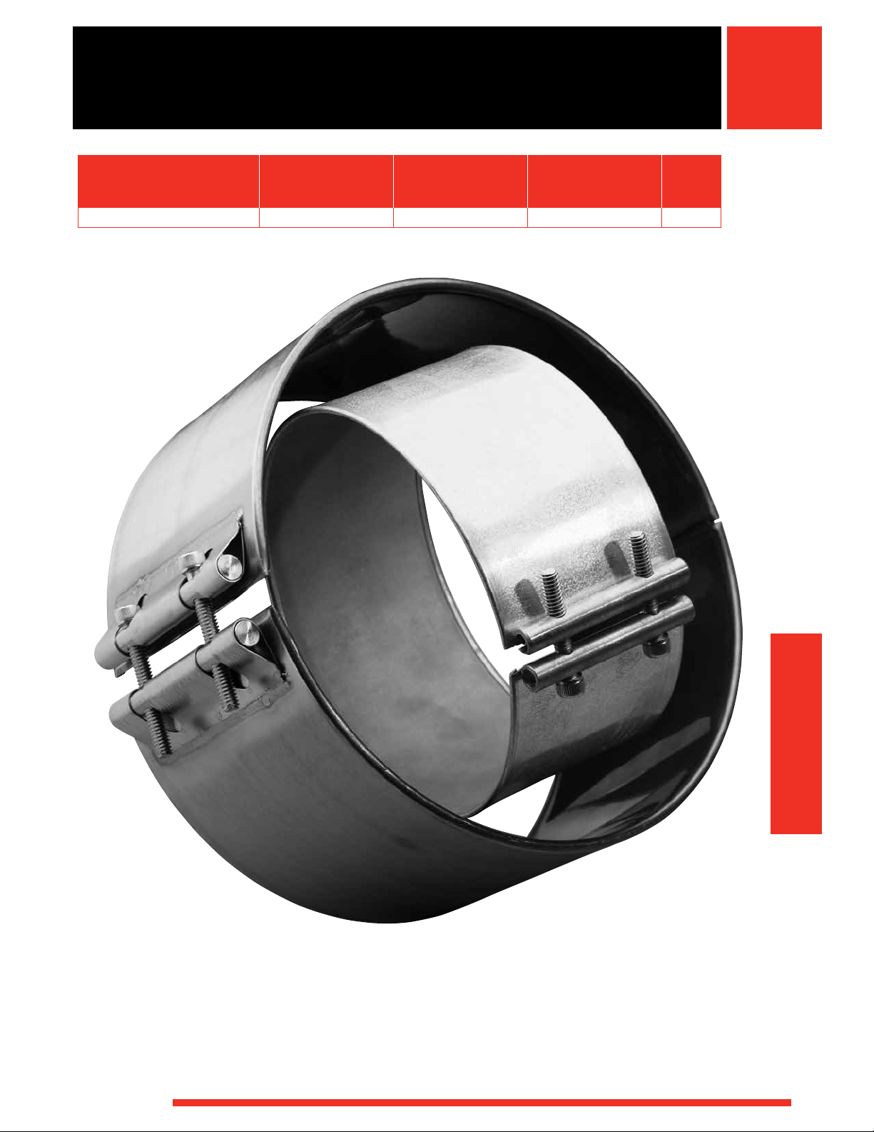
Band/Barrel Heaters
Max. Operating Typical Max.
Temperatures Watt Densities
Band/Barrel Heaters Sheath Materials °F °C W/in2 W/cm
Mineral Insulated (MI) Stainless steel 1400 760 100 15.5 493
2
Page
Band/Barrel Heaters
WATLOW
®
491
Page 2

492
WATLOW
®
Page 3
Band/Barrel Heaters
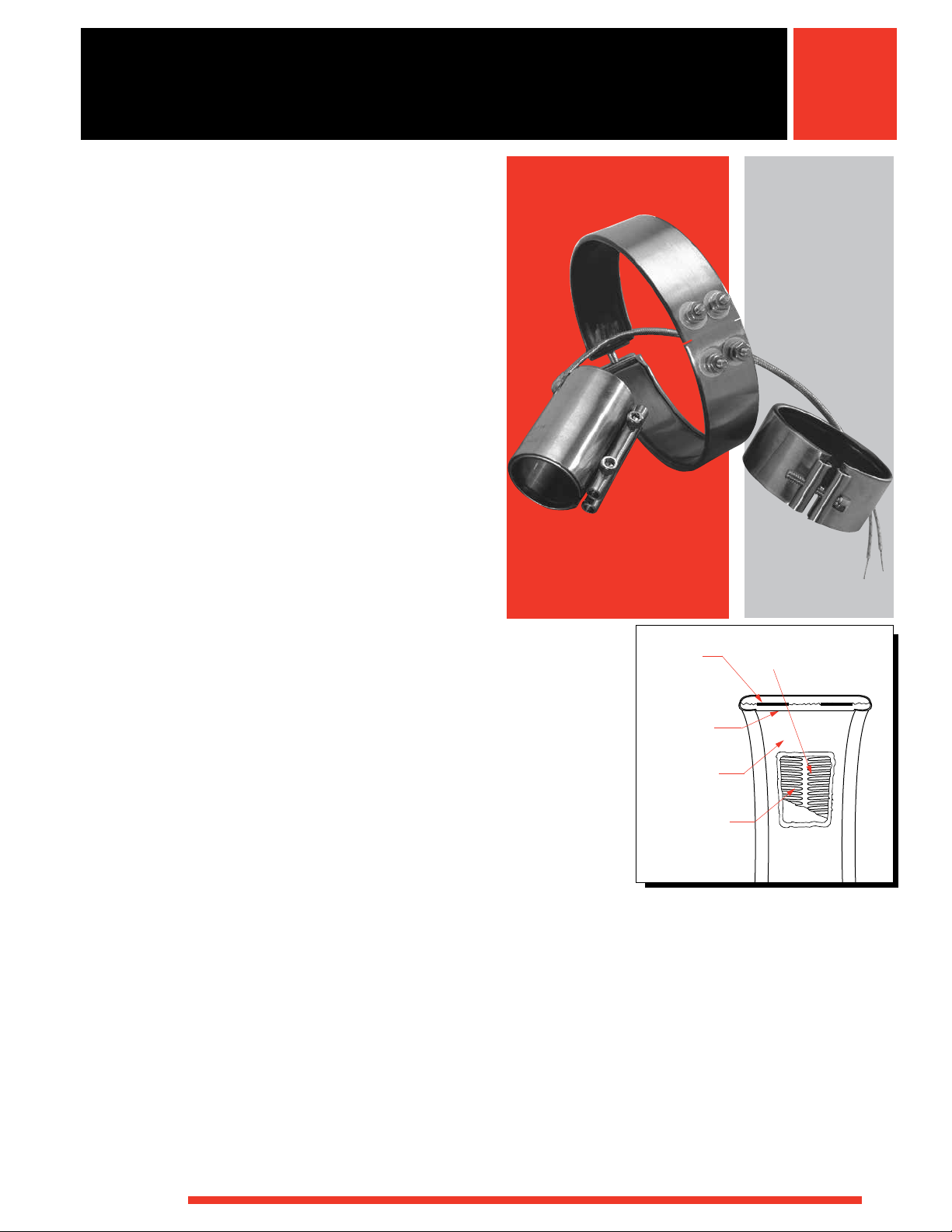
Mineral Insulated (MI) Band Heaters
The mineral insulated (MI) band heater from Watlow® is
a high-performance heater that incorporates Watlow’s
exclusive mineral insulation. This material offers much
higher thermal conductivity than mica and hard ceramic
insulators that are used in conventional heaters.
A thin layer of the “high” thermally conductive MI material
electrically insulates the element wire from the inside
diameter of the heater sheath. A thicker, low thermally
conductivity layer backs up the element wire directing the
heat inward toward the part being heated. The result is
more efficient heat transfer, which lowers element wire
temperatures and increases heater life.
Performance Capabilities
• Heater operating temperatures up to 1400°F (760°C)
• Watt densities up to 100 W/in
on large diameter barrel bands
• Maximum voltage to 480V
2
(15.5 W/cm2) available
Features and Benefits
High thermal conductivity of MI and low mass
construction
• Provides an almost instant response to temperature
control
• Eliminates thermal lag and temperature overshoot
associated with ceramic insulated heaters
Operating temperatures up to 1400°F (760°C)
• Allows safe melting of resins such as PEEK™,
Teflon®, Ultem® and Zytel®
Higher watt densities
• Contributes to faster heat-up and throughput for
increased productivity
Stainless steel cover and side fold design
• Resists contamination from overflow of plastic or other
free-flowing materials
Attached clamp bars
• Eliminates cumbersome clamping straps to ease
installation
Typical Applications
• Extruders
• Blown film dies
• Injection molding machines
• Other cylinder heating applications
Thick Low
Conductivity
MI Backing
Thin High
Conductivity
MI Insulation
430 Stainless
Steel Sheath
Element Wire in
Mineral Insulation
Coiled or Sinuated
Wire Element
WATLOW
®
493
Page 4
Band/Barrel Heaters
Mineral Insulated (MI) Band Heaters
Applications and Technical Data
The Physical Limitations of Variations table shows the
availability of widths, inside diameters and terminations
If the application requires a heater exceeding limitations
shown, contact your Watlow representative.
for Watlow’s MI band, barrel and nozzle heaters. To
ensure available terminations meet application needs,
refer to the termination variation illustrations in this
section.
Physical Limitations of Variations
I.D. Available—in. (mm)
1 pc. Construction Expandable 2 pc. Construction
Width Min. Max. Min. Max. Min. Max.
in. (mm) in. (mm) in. (mm) in. (mm) in. (mm) in. (mm) in. (mm) Available Terminations
1 (25) 1 (25) – 6 (152) 3 (76) – 12 (305) 3 (76) – 12 (305) All
3
1
/8 (35) 1 (25) – 3 (76) 3 (76) – 6 (152) 3 (76) – 6 (152) All - Except SLE
1
1
/2 (38) 1 (25) – 14 (356) 3 (76) – 14 (356) 3 (76) – 28 (711) All
2 (51) 1
1
2
/2 (64) 11/4 (32) – 14 (356) 3 (76) – 14 (356) 3 (76) – 28 (711) All
3 (76) 1
1
3
/2 (89) 13/4 (45) – 14 (356) 3 (76) – 14 (356) 3 (76) – 28 (711) All - Except 90° “B” Leads
4 (102) 2 (51) – 14 (356) 3 (76) – 14 (356) 3 (76) – 28 (711) All
1
4
/2 (114) 21/4 (57) – 14 (356) 3 (76) – 14 (356) 3 (76) – 28 (711) All
5 (127) 2
1
5
/2 (140) 23/4 (70) – 14 (356) 3 (76) – 14 (356) 4 (102) – 28 (711) Post Terminals, SLE only
6 (152) 3 (76) – 14 (356) 3 (76) – 14 (356) 4 (102) – 28 (711) All
7 (178) 4 (102) – 14 (356) Post Terminals, SLE only
1
/4 (32) – 14 (356) 3 (76) – 14 (356) 3 (76) – 28 (711) All
1
/2 (38) – 14 (356) 3 (76) – 14 (356) 3 (76) – 28 (711) All
1
/2 (64) – 14 (356) 3 (76) – 14 (356) 4 (102) – 28 (711) All - Except 90° “B” Leads
General Limitations
• Maximum width of 1 in. (25 mm) diameter heater:
11/2 in. (38 mm)
• Maximum heater width: 2x heater diameter
• Minimum I.D. for Type B, C, E and H leads:
1 in. (25 mm)
• Minimum I.D. for Type B—90° leads: 1
• Maximum lead amperes: 12.5A per pair
• SLE maximum: 17.0A
• Maximum amperes (post terminals): 30A per pair
• Minimum diameter and width for SLE: 4 in. x 1
(102 mm x 38 mm) width
• 90° leads not available over 250VAC
• Minimum I.D. for post terminals: 1
• Actual width for 7 in. (178 mm) wide heater:
7
6
/8 in. (175 mm)
1
/8 in. (29 mm)
1
/4 in. (32 mm)
1
/2 in.
Gaps
• ≤ 3 in. = 1/8 in. nomin al
• 3 in.
≤ 6 in. =
• 6 in.
≤14 in. =
• >14 in. =
1
/4 in. nominal ±1/8 in.
3
/8 in. nominal ±1/8 in.
1
/2 in. nominal ±1/4 in.
494
WATLOW
®
Page 5
Band/Barrel Heaters
03
Mineral Insulated (MI) Band Heaters
Applications and Technical Data (Continued)
Calculating Watt Density
Watt density is the amount of wattage per square inch of
heated area. To determine watt density, divide the total
wattage by the heated area.
Watt Density =
Total Watts
Heated Area
To apply this equation, the term “heated area” must be
defined. Heated area is the total contact surface of the
heater less the areas of no-heat found around terminals,
mounting holes, etc.
Heated Area = Total Contact Area - No-Heat Area
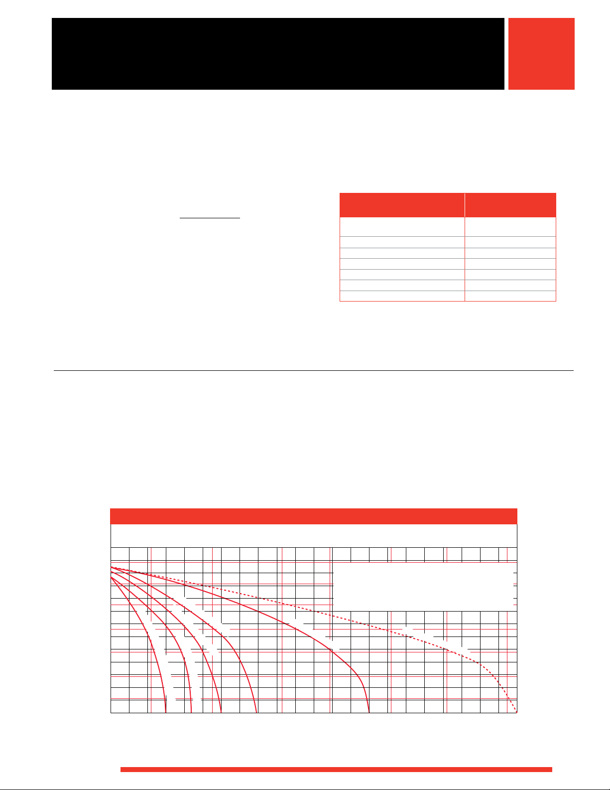
Maximum Allowable Watt Density
The following derating factors apply to the Maximum
Allowable Watt Density chart, which are displayed in both
inches and millimeters. Review these factors and the
chart to determine the correct watt density curve for
the application.
Derating Factors:
• For units over 2 in. (51 mm) in width, multiply the watt
density by 0.80.
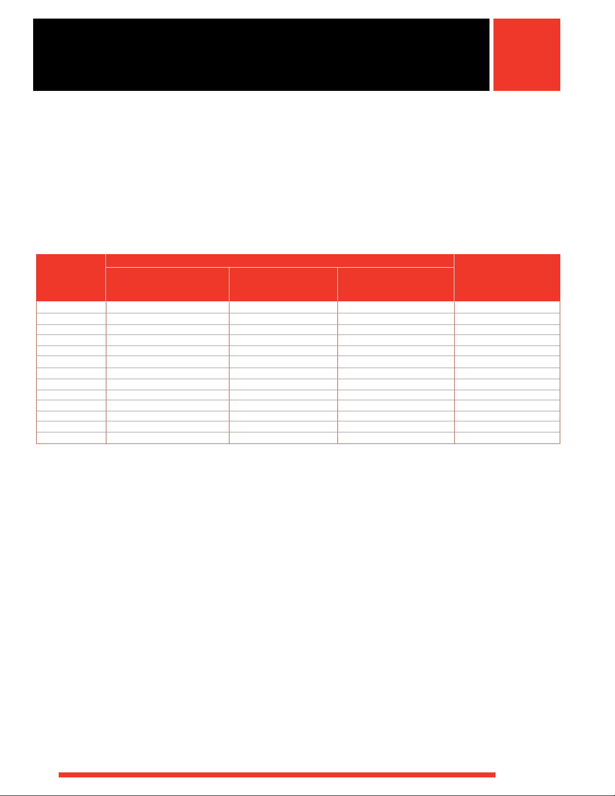
To calculate the heated area:
1. Locate the no-heat factor from the chart below that
corresponds to the type of heater being considered.
Type No-Heat Factor
in.
1 pc. lead unit Type B, C, H, E
or 90°B
1 pc. post terminal 1.60
1 pc. expandable post term 3.18
1 pc. expandable lead unit 3.00
True 2 pc. post term 3.20
True 2 pc. leads 2.74
SLE 3.68
1.37
2. To use the formula below, insert the no-heat factors,
diameter and width (in inches).
Heated Area =
(3.14 x Diameter - No-Heat Factor) x Width
• For applications where unusual operating conditions
are present, such as irregular mounting surfaces,
contact your Watlow representative for watt density
limitations.
• For two-piece units used in vertical applications, refer
to Clamping Matrix Application Guide on page 496.
• For applications where insulating blankets are used,
multiply watt density by 0.75.
1300
1200
1100
1000
900
800
700
600
500
Part Temperature — °F
400
300
200
WATLOW
Maximum Allowable Watt Density
Watt Density - W/cm
5101520253
6 in. (152 mm) I.D.
1
10 20 30 40 50 60 70 80 90 100 110 120 130 140 150 160 170 180 190 200 210 220 230
®
10 in. (254 mm) I.D.
4
i
n
.
(
3
5
6
m
m
)
I
.
D
.
&
2
P
i
e
c
e
3 in. (76 mm) I.D.
1
2
i
n
.
(
3
0
5
m
m
)
I
.
D
.
Watt Density — W/in
2
Allowable watt density for 11⁄2 in. (38 mm) wide
MI band heaters:
• Moderate cycling
• Heaters properly clamped
• Heaters mounted on a smooth cylinder
1
1
/
2
in. (38 mm) I.D.
2
5
700
600
500
400
300
200
100
Part Temperature — °C
495
Page 6

Band/Barrel Heaters
Mineral Insulated (MI) Band Heaters
Applications and Technical Data (Continued)
• Review the Watt Density chart to ensure the
• Description of guideline letters are at the bottom of
application does not exceed the maximum watt
density at operating temperature after applying
• Note: Upward arrows are up to and not including
derating factors.
• Locate clamping guideline for unit diameter, width and
watt density.
MI Band Clamping Matrix Application Guide
Dia. 8 ≥ 10 10 ≥ 12 12 ≥ 14 14 ≥ 16 16 ≥ 18 18 ≥ 20 20 ≥ 22 22 ≥ 24 24 ≥ 26 26 ≥ 28
11/2 to
41/2 to
11/2 to
41/2 to
11/2 to
41/2 to
11/2 to
41/2 to
11/2 to
4 in.
7 in.
4 in.
7 in.
4 in.
7 in.
4 in.
Width
(38 to
(114
(38 to
(114
(38 to
102
to 178
102
mm)
mm)
80
75
70
2
65
60
55
50
45
40
35
Watt Density–W/in
30
25
20
15
10
0
Note: 1 in. (25 mm) wide heaters use welded barrel nuts rather than clamp bars.
B
B
A
A
A = Clamp bars, expandable or one piece construction Width Clamp Points at Each Gap
B = Spring clamps, expandable or one piece construction ≥ 5 in. (127 mm) 3
C = Spring clamps, at one gap, welded barrel nuts at other gap ≥ 3 in. (76 mm) 2
D = Spring clamps, spring clamps at both gaps < 3 in. (76 mm) 1
mm)
B
A
to 178
mm)
B
A
102
mm)
B
A
(114
to 178
mm)
B
A
(38 to
102
mm)
D
C
7 in.
(114
to 178
mm)
DCDCD
4 in.
(38 to
102
mm)
41/2 to
7 in.
(114
to 178
mm)
the MI Band Clamping Matrix Application Guide.
specified watt density. Downward arrows are greater
than or equal to specified watt density.
11/2 to
41/2 to
11/2 to
41/2 to
11/2 to
41/2 to
11/2 to
41/2 to
4 in.
7 in.
4 in.
7 in.
(38 to
(114
to 178
mm)
(38 to
102
mm)
C
102
mm)
Above Recommended Watt Densities
Contact your Watlow Representative
DCDCD
C
(114
to 178
mm)
D
C
4 in.
(38 to
102
mm)
D
C
7 in.
(114
to 178
mm)
D
C
4 in.
(38 to
102
mm)
D
C
7 in.
(114
to 178
mm)
D
C
11/2 to
4 in.
(38 to
102
mm)
DCD
41/2 to
7 in.
(114
to 178
mm)
C
496
WATLOW
®
Page 7

Band/Barrel Heaters
Mineral Insulated (MI) Band Heaters
Termination Variations
Post Terminals
Stock
0.625 in. (15.9 mm)
Nom.
0.75 in.
(19 mm)
0.16 in.
(4.1 mm)
Post terminals provide optimum connections. Screw
thread is 10-24. To order, specify post terminals
(metric threads available).
1.25 in.
(32 mm)
Width ±0.0625 in.
(1.6 mm)
Lead Wire
Heaters rated at less than 250VAC use UL® approved
lead insulation for operations to 480°F (250°C) as
standard. Lead insulation UL® rated for operation to 840°F
(450°C) is available for high-temperature applications
where the leads are shrouded or enclosed with the
heater. These leads are available in any of the Type
B with loose braid as well as Types E, F and H lead
configurations. All heaters rated at more than 250VAC
use this wire. When ordering, specify 850°F (450˚C) wire.
Leads Type B, Type B - 90° rotation, Type B - 180°
rotation or Type C: Two fiberglass-insulated lead wires
exit in a single metal braid for good abrasion protection,
lead flexibility and wiring convenience. Leads are 2 in.
(51 mm) longer than braid. Shipped with 12 in. (305 mm)
leads, unless longer length is specified. To order, specify
type and length.
Type B
Stock
0.36 in.
(9 mm)
12 in.
(305 mm)
0.81 in.
(21 mm)
Type B - 90° Rotation
Non-Stock
0.36 in.
(9 mm)
1.25 in.
(32 mm)
Type B - 180° Rotation
Stock
0.16 in.
(4.1 mm)
I.D.
0.625 in.
(15.9 mm)
Nom.
Width ±0.0625 in.
(1.6 mm)
WATLOW
I.D.
1.25 in.
(32 mm)
®
0.16 in.
(4.1 mm)
Width ±0.0625 in.
(1.6 mm)
1.25 in.
(32 mm)
Width ±0.0625 in.
(1.6 mm)
497
Page 8

Band/Barrel Heaters
Mineral Insulated (MI) Band Heaters
Termination Variations (Continued)
Lead Wire (Continued)
Type C
Stock
0.656 in.
(16.7 mm) Dia.
0.191 in.
(4.9 mm)
I.D.
0.557 in.
(14.1 mm)
0.75 in.
(19 mm) Nom.
Type F
Stock
0.191 in.
(4.9 mm)
I.D.
1.25 in.
(32 mm)
0.656 in.
(16.7 mm) Dia.
0.635 in.
(16.1 mm)
0.75 in.
(19 mm) Dia.
Width ±0.0625 in.
(1.6 mm)
1.25 in.
(32 mm)
Width ±0.0625 in.
(1.6 mm)
Type E
Stock
0.44 in.
(11.2 mm) Dia.
0.656 in.
0.191 in.
(4.9 mm)
I.D.
1.25 in.
(32 mm)
(16.7 mm) Dia.
0.635 in.
(16.1 mm)
Width ±0.0625 in.
(1.6 mm)
0.75 in.
(19 mm) Nom.
Type E: Loose metal braid encloses two fiberglass leads
for good abrasion protection, lead flexibility and wiring
convenience. Leads are 2 in. (51 mm) longer than the
braid. Shipped with 12 in. (305 mm) leads, unless longer
length is specified. To order, specify Type E and length.
Type F: Loose fiberglass sleeving encloses two fiberglass
leads for additional insulation protection where high
temperature or minor abrasion is present. Leads are
2 in. (51 mm) longer than the sleeving. To order, specify
Type F and length.
Type H
Stock
0.656 in.
(16.7 mm) Dia.
0.191 in.
(4.9 mm)
I.D.
1.25 in.
(32 mm)
0.635 in.
(16.1 mm)
0.75 in.
(19 mm) Nom.
Width ±0.0625 in.
(1.6 mm)
Type H: A flexible steel hose encloses the leads for
maximum abrasion protection. Leads are 2 in. (51 mm)
longer than hose. Shipped with 12 in. (305 mm) leads,
unless longer length is specified. To order, specify
Type H and length.
498
WATLOW
®
Page 9

Band/Barrel Heaters
f
Mineral Insulated (MI) Band Heaters
Termination Variations (Continued)
Lead Wire (Continued)
Type K
Stock
Type SLE
0.656 in.
0.191 in.
(4.9 mm)
I.D.
1.25 in.
(32 mm)
(16.7 mm) Dia.
0.557 in.
(14.1 mm)
0.75 in.
(19 mm) Nom.
Width ±0.0625 in.
(1.6 mm)
Type K: Flexible lead wires exit vertically from the heater.
These leads can be bent adjacent to the heater
for a quick and easy connection. To order, specify
Type K and length.
Variations
Thermocouple
0.4375 in.
(11.1 mm)
Strain Relie
Two fiberglass lead wires exit a single, tightly woven metal
braid at a right angle on the expandable construction vs.
two sets of leads. The minimum diameter capability is
4 in. (102 mm). Minimum width capability is 1
1
/2 in.
(38 mm). To order, specify Type SLE and length.
Heavy Duty Strain Relief
0.25 in.
(6 mm)
Spot Welded to
Heater Sheath
ASTM Type J or K thermocouples are available on lead
Type B with loose braid and fiberglass sleeving. They are
also available on E, F and H leads. The thermocouple
junction, spot-welded to the heater sheath, provides a
signal for measuring relative heater temperature.
A separate thermocouple is available.
WATLOW
®
Heavy duty strain relief is recommended for applications
where there is great stress or continued flexing of the
leads. The strain relief is available on Type B,
Type B - 90° and
Type B
-
180°
leads only. To order,
specify heavy-duty strain relief. Note: not available
with loose braid or fiberglass sleeving.
499
Page 10

Band/Barrel Heaters
Mineral Insulated (MI) Band Heaters
Variations (Continued)
Expandable Heaters With Post Terminals or Leads
Expandable heaters are two-piece units with a common
top metal allowing the heater to expand open to the
full diameter of the barrel. On expandable bands, each
half will be one half of the total wattage. Plus, on both
expandable and two-piece bands, each half will be rated
at full operating voltage, unless otherwise specified.
MI band heaters 11/2 in. (38 mm) wide or greater have
post terminals located next to the expansion joint. Leads
may be located anywhere along the circumference except
near the gap and at the expansion joint. Two sets of leads
required.
On 1 in. (25 mm) wide MI band heaters, post terminals
will be located 90° from the expansion joint. Leads may
be located anywhere along the circumference except
near the gap and at the expansion joint. Two sets of
leads are required. To order, specify expandable.
Expandable heaters are designed to be opened for
new installation only.
Metallic Terminal Box
3½ in. for 3½-5⁄ in. I.D.
4 in. for 6-28 in. I.D.
1⁄ in.
(46 mm)
1⁄ in.
(36.5 mm)
Metallic terminal boxes are available from stock on 31/2 in.
inside diameter x 11/2 in. wide (89 mm x 38 mm) or larger
heaters. Terminal boxes, which attach directly to the heater,
act as a safety feature by covering the terminals. Conduit
may be attached to the box through 7/8 in. (22 mm)
diameter holes in the ends of the box. Two-piece heaters
require two boxes. To order, specify terminal box.
MI Band Heater with Holes
Ceramic Terminal Cover
Ceramic covers, with openings for leads, are screwed
on to post terminals, providing a convenient, economical
insulator. To order, specify part number Z-4918 and
quantity. For metric sizes specify thread needed.
Note: Ceramic terminal covers will not fit on some stock
expandable MI bands or nozzles. Contact your Watlow
representative for more information.
500
MI band heaters with holes are available on all widths
except 1 in. (25 mm) wide. Contact your Watlow
representative for hole sizes and location constraints.
To order, specify hole size and location. The inside
diameter minimum is 3 in. (76 mm). Note: a minimum
charge per line item applies.
WATLOW
®
Page 11

Band/Barrel Heaters
Mineral Insulated (MI) Band Heaters
Clamping Variations
Tig-Welded Barrel Nuts with Spring Loaded Clamping
5⁄16 in. 18 Screw
5.8 in. (147 mm)
0.75 in.
(19 mm)
Welded barrel nuts with spring loaded clamping are
used to maintain a tight heater fit on large barrels during
start-up. This clamping variation is recommended for all
MI band heaters greater than 14 in. (356 mm) in diameter
and 11/2 in. (38 mm) or greater in width. Refer to MI Band
Clamping Matrix Application Guide. For smaller diameter
heaters, it is an option and must be ordered separately.
To order, specify spring loaded clamping.
Low-Profile Tig-Welded Barrel Nuts
Low-profile barrel nuts are available on all widths and
provide a clearance of 0.470 in. (12 mm). However, this
value can be higher depending on how far the clamp
screw extends past the barrel nut. To order, specify
low-profile tig-welded barrel nuts.
Tig-Welded Barrel Nuts
¼
in. 2 Screw
0.563 in.
(14.3 mm)
Tig Welded
Tig-welded barrel nuts can function like a hinge to allow
two-piece heaters to be more easily installed. If a large
gap is specified to provide access for instrumentation,
tig-welded barrel nuts can be situated in such a way
that the clamp screws do not interfere with the sensor.
To order, specify gap size and sensor location.
Note: a gap greater than 1 in. (25 mm) wide is
considered extended capability.
Options
Thermocouple Pocket
Low-Profile Clamp Bars
I.D.
0.45 in.
(11.4 mm)
Low-profile clamp bars are available on both
1 in. (25 mm) and 11/2 in. (38 mm) wide heaters, for
wider widths contact your Watlow representative. Watlow
recommends not using low-profile clamping on diameters
and widths greater than 3 in. (76 mm). The bars are
1
/4 in. (6 mm) diameter with an 8-32 screw. To order,
specify low-profile clamp bars.
WATLOW
®
8-32 Screw
A thermocouple pocket welded to the surface accepts a
0.063 in. (2 mm) diameter thermocouple (not included).
This option provides accurate temperature sensing of the
heater and easy thermocouple replacement.
501
Page 12

Band/Barrel Heaters
4 in.
2 in.
Extended Capabilities For
Mineral Insulated (MI) Band Heaters
Variations
xtEndEd
E
apability
C
High Temperature “Quick Disconnect”
European Style Plugs
(51 mm)
(102 mm)
15⁄8 in.
(41.3 mm)
2 7⁄8 in.
(73 mm)
2 ¼ in.
(57 mm)
15⁄16 in.
(33.3 mm)
Vertical Horizontal
They provide the simplest and safest way to apply power
to band heaters. The combination of high-temperature
male and female “quick disconnect” plug assemblies
eliminates all live exposed terminals and electrical wiring
that can be a potential hazard to employees or machine.
Maximum 15 amperes at 240VAC, maximum 240V.
To order, specify vertical or horizontal European plug.
Ground Wire
Insulated ground wire is available, contact your Watlow
representative.
Outside Diameter Heater
3 in. (76 mm) min. O.D,
14 in. (356 mm) max.
0.420 in.
(10.7 mm)
0.875 in.
(22.2 mm)
Two fiberglass-insulated lead wires rated to 840°F (450°C)
exit a metal braid 180° opposite from gap, Type B outside
diameter designed and constructed to mate with inside
diameter of cylinders. Maximum width for outside
diameter heaters is 6 in. (152 mm). To order, specify
outside diameter and width of heater.
502
WATLOW
®
Page 13

ww
RAPID SHIP
Band/Barrel Heaters
Mineral Insulated (MI) Band Heaters
Heater Part Numbers
Watt Approx.
I.D. Width Density Net Wt. Part
in. (mm) in. (mm) Construction Volts Watts W/in2 (W/cm2) Termination lbs (kg) Delivery Number
1 (25) 1 (25) 1 pc 120 150 92 (14.2) Type B,C,E, F or H 0.1 (0.05) RS MB1A1AN1
1 (25) 1 pc 120 100 61 (9.4) Type B,C,E, F or H 0.1 (0.05) RS MB1A1AN2
1 (25) 1 pc 120 200 122 (18.9) Type B,C,E, F or H 0.1 (0.05) RS MB1A1AN3
1 (25) 1 pc 240 200 122 (18.9) Type B,C,E, F or H 0.1 (0.05) RS MB1A1AN4
1 1/2 (38) 1 pc 240 300 106 (16.4) Type B,C,E, F or H 0.1 (0.05) RS MB1A1JN1
1 1/2 (38) 1 pc 120 300 106 (16.4) Type B,C,E, F or H 0.1 (0.05) RS MB1A1JN2
11/2 (38) 1 pc 240 200 70 (10.8) Type B,C,E, F or H 0.1 (0.05) RS MB1A1JN3
11/2 (38) 1 pc 120 200 70 (10.8) Type B,C,E, F or H 0.1 (0.05)
1 1/2 (38) 1 pc 240 400 141 (21.8) Type B,C,E, F or H 0.1 (0.05) RS MB1A1JN5
11/4 (32) 1 (25) 1 pc 240 250 104 (16.1) Type B,C,E, F or H 0.1 (0.05) RS MB1E1AN1
1 (25) 1 pc 120 250 104 (16.1) Type B,C,E, F or H 0.1 (0.05) RS MB1E1AN2
1 (25) 1 pc 240 300 124 (19.2) Type B,C,E, F or H 0.1 (0.05) M MB1E1AN3
1 1/2 (38) 1 pc 240 350 87 (13.5) Type B,C,E, F or H 0.2 (0.09) RS MB1E1JN1
1 1/2 (38) 1 pc 120 350 87 (13.5) Type B,C,E, F or H 0.2 (0.09) RS MB1E1JN2
1 1/2 (38) 1 pc 240 450 112 (17.3) Type B,C,E, F or H 0.2 (0.09) M MB1E1JN3
11/2 (38) 1 (25) 1 pc 240 300 93 (14.4) Type B,C,E, F or H 0.1 (0.05) M MB1J1AN1
1 (25) 1 pc 120 300 93 (14.4) Type B,C,E, F or H 0.1 (0.05) RS MB1J1AN2
1 (25) 1 pc 240 200 62 (9.6) Type B,C,E, F or H 0.1 (0.05) RS MB1J1AN3
1 (25) 1 pc 120 200 62 (9.6) Type B,C,E, F or H 0.1 (0.05) RS MB1J1AN4
1 (25) 1 pc 240 400 125 (19.3) Type B,C,E, F or H 0.1 (0.05) RS MB1J1AN5
11/2 (38) 1 pc 120 300 62 (9.6) Type B,C,E, F or H 0.2 (0.09) RS MB1J1JN1
1 1/2 (38) 1 pc 240 450 87 (13.5) Type B,C,E, F or H 0.2 (0.09) RS MB1J1JN2
1 1/2 (38) 1 pc 240 300 62 (9.6) Type B,C,E, F or H 0.2 (0.09) RS MB1J1JN3
1 1/2 (38) 1 pc 240 600 116 (17.9) Type B,C,E, F or H 0.2 (0.09) M MB1J1JN4
1 1/2 (38) 1 pc 240 300 62 (9.6) Post 0.2 (0.09) M MB1J1JP4
1 1/2 (38) 1 pc 240 450 96 (14.8) Post 0.2 (0.09) RS MB1J1JP6
2 (51) 1 pc 240 450 57 (8.8) Type B,C,E, F or H 0.3 (0.14) RS MB1J2AN1
2 (51) 1 pc 240 300 42 (6.5) Type B,C,E, F or H 0.3 (0.14) RS MB1J2AN2
2 (51) 1 pc 240 900 125 (19.3) Type B,C,E, F or H 0.3 (0.14) RS MB1J2AN3
3 (76) 1 pc 240 500 45 (7.0) Type B,C,E, F or H 0.4 (0.18) RS MB1J3AN1
3 (76) 1 pc 240 350 31 (4.8) Type B,C,E, F or H 0.4 (0.18) M MB1J3AN2
3 (76) 1 pc 240 1000 104 (16.1) Type B,C,E, F or H 0.4 (0.18) M MB1J3AN3
13/4 (45) 1 3/8 (35) 1 pc 240 450 83 (12.9) 36 in. 90° Type B 0.2 (0.09) RS
braid w/HD strain
relief
11/2 (38) 1 pc 240 300 47 (7.3) Type B,C,E, F or H 0.2 (0.09) RS MB1N1JN1
1 1/2 (38) 1 pc 120 300 50 (7.7) Type B,C,E, F or H 0.2 (0.09) RS MB1N1JN2
1 1/2 (38) 1 pc 240 700 110 (17.0) Type B,C,E, F or H 0.2 (0.09) RS MB1N1JN3
2 (51) 1 pc 240 750 86 (13.3) Type B,C,E, F or H 0.3 (0.14) M MB1N2AN1
2 (51) 1 (25) 1 pc 240 350 73 (11.3) Type B,C,E, F or H 0.2 (0.09) RS MB2A1AN1
1 (25) 1 pc 120 350 73 (11.3) Type B,C,E, F or H 0.2 (0.09) RS MB2A1AN2
1 (25) 1 pc 240 450 94 (14.5) Type B,C,E, F or H 0.2 (0.09) RS MB2A1AN3
1 (25) 1 pc 240 350 73 (10.3) 36 in. 90° Type B 0.2 (0.09) RS
braid w/HD strain
relief
M
MB1A1JN4
MB1N1GX3A
MB2A1AX6B
CONTINUED
• RS - Next day shipment
• M - Manufacturing lead times
WATLOW
®
Notes:
All lead units are available with any length Type B, C, E, F or Type H leads.
Type B 90° rotation not available as RAPID SHIP.
503
Page 14

Band/Barrel Heaters
RAPID SHIP
Mineral Insulated (MI) Band Heaters
Heater Part Numbers (Continued)
Watt Approx.
I.D. Width Density Net Wt. Part
in. (mm) in. (mm) Construction Volts Watts W/in2 (W/cm2) Termination lbs (kg) Delivery Number
2 (51) 11/2 (38) 1pc 240 400 53 (8.2) Type B,C,E, F or H 0.3 (0.14) RS MB2A1JN1
11/2 (38) 1pc 240 1000 132 (20.4) Type B,C,E, F or H 0.3 (0.14) M MB2A1JN2
2 (51) 1pc 240 750 75 (11.6) Type B,C,E, F or H 0.4 (0.18) M MB2A2AN1
2 (51) 1pc 240 1200 125 (19.3) Type B,C,E, F or H 0.4 (0.18) RS MB2A2AN2
2 (51) 1pc 240 750 75 (11.6) 36 in. 90° Type B 0.2 (0.09) RS
braid w/HD strain
relief
21/4 (57) 2 (51) 1pc 240 750 63 (9.7) 120 in. 180° Type B 0.2 (0.09) RS
braid w/HD strain
relief
21/2 (64) 1 pc 240 1000 72 (11.2) Type B,C,E, F or H 0.5 (0.23) RS MB2E2JN1
21/2 (64) 1 (25) 1 pc 240 400 63 (9.7) Type B,C,E, F or H 0.2 (0.09) RS MB2J1AN1
11/2 (38) 1 pc 240 500 50 (7.7) Type B,C,E, F or H 0.4 (0.18) RS MB2J1JN1
3 (76) 1 (25) 1 pc 240 400 54 (8.4) Post 0.3 (0.14) M MB3A1AP1
11/2 (38) 1 pc 240 500 40 (6.2) Post 0.4 (0.18) RS MB3A1JP1
11/2 (38) 2 pc exp 230/460 525 53 (8.2) Post 0.4 (0.18) M ME3A1JP10
31/2 (89) 2 (51) 1 pc 240 800 42 (6.5) Post 0.7 (0.32) RS MB3J2AP2
35/8 (92) 11/2 (38) 2 pc exp 230/460 650 51 (7.9) Post 0.5 (0.23) M ME3L1JP5
4 (102) 1 (25) 1 pc 240 700 62 (9.6) Post 0.4 (0.18) RS MB4A1AP1
11/2 (38) 1 pc 240 800 48 (7.4) Post 0.6 (0.27) RS MB4A1JP2
11/2 (38) 2 pc exp 230/460 625 43 (6.7) Post 0.6 (0.27) RS ME4A1JP11
11/2 (38) 2 pc exp 230/460 725 50 (7.8) Post 0.6 (0.27) RS ME4A1JP12
41/2 (114) 21/2 (64) 1pc 240 1250 40 (6.2) Post 1.0 (0.45) RS MB4J2JP1
5 (127) 11/2 (38) 2 pc exp 240/480 1000 52 (8.1) Post 0.8 (0.36) RS ME5A1JP8
51/4 (133) 11/2 (38) 2 pc exp 240/480 1000 48 (7.4) Post 0.8 (0.36) M ME5E1JP1
11/2 (38) 2 pc exp 230/460 600 29 (4.5) Post 0.7 (0.32) M ME5E1JP9
3 (76) 2 pc exp 230/460 1700 40 (6.2) Post 1.5 (0.68) RS ME5E3AP5
41/2 (114) 2 pc exp 230/460 2400 38 (5.9) Post 2.2 (1.00) RS ME5E4JP2
41/2 (114) 2 pc exp 230/460 2700 43 (6.6) Post 2.2 (1.00) M ME5E4JP3
51/2 (140) 11/2 (38) 2 pc exp 240/480 1000 46 (7.1) Post 0.9 (0.40) RS ME5J1JP1
6 (152) 11/2 (38) 2 pc exp 240/480 1000 41 (6.4) Post 0.9 (0.40) M ME6A1JP2
61/2 (165) 11/2 (38) 2 pc exp 240/480 1250 47 (7.3) Post 1.0 (0.45) RS ME6J1JP5
63/4 (171) 11/2 (38) 2 pc exp 230/460 815 29 (4.5) Post 0.9 (0.40) M ME6N1JP6
11/2 (38) 2 pc exp 230/460 1000 36 (5.6) Post 0.9 (0.40) M ME6N1JP7
4 (102) 2 pc exp 230/460 2600 35 (5.4) Post 2.5 (1.10) M ME6N4AP2
5 (127) 2 pc exp 230/460 3700 40 (6.2) Post 3.2 (1.50) M ME6N5AP3
6 (152) 2 pc exp 230/460 3750 33 (5.1) Post 3.8 (1.70) M ME6N6AP5
7 (178) 11/2 (38) 2 pc exp 240/480 1250 43 (6.6) Post 1.1 (0.50) M ME7A1JP4
71/2 (191) 11/2 (38) 2 pc exp 240/480 1500 47 (7.3) Post 1.1 (0.50) M ME7J1JP4
75/8 (194) 3 (76) 2 pc exp 230/460 1800 28 (4.3) Post 2.2 (1.00) M ME7L3AP1
8 (203) 11/2 (38) 2 pc exp 240/480 1250 37 (5.7) Post 1.2 (0.54) M ME8A1JP4
9 (229) 11/2 (38) 2 pc exp 240/480 1500 39 (6.0) Post 1.4 (0.64) M ME9A1JP1
91/2 (241) 3 (76) 2 pc exp 230/460 3000 37 (5.7) Post 2.6 (1.20) M ME9J3AP2
111/4 (286) 3 (76) 2 pc exp 230/460 2400 24 (3.7) Post 3.2 (1.50) M ME11E3AP2
5 (127) 2 pc exp 230/460 5100 31 (4.8) Post 5.2 (2.40) M ME11E5AP1
Notes:
All lead units are available with any length Type B, C, E, F or Type H leads.
• RS - Next day shipment
Type B 90° rotation not available as RAPID SHIP.
• M - Manufacturing lead times
MB2A2AX2A
MB2E2AX7
504
WATLOW
®
 Loading...