

Page 1
6 mm (
1
/
4
in.)
No-Heat
Heated
Length
6 mm (
1
/
4
in.)
No-Heat
WW AA TT LL OO W
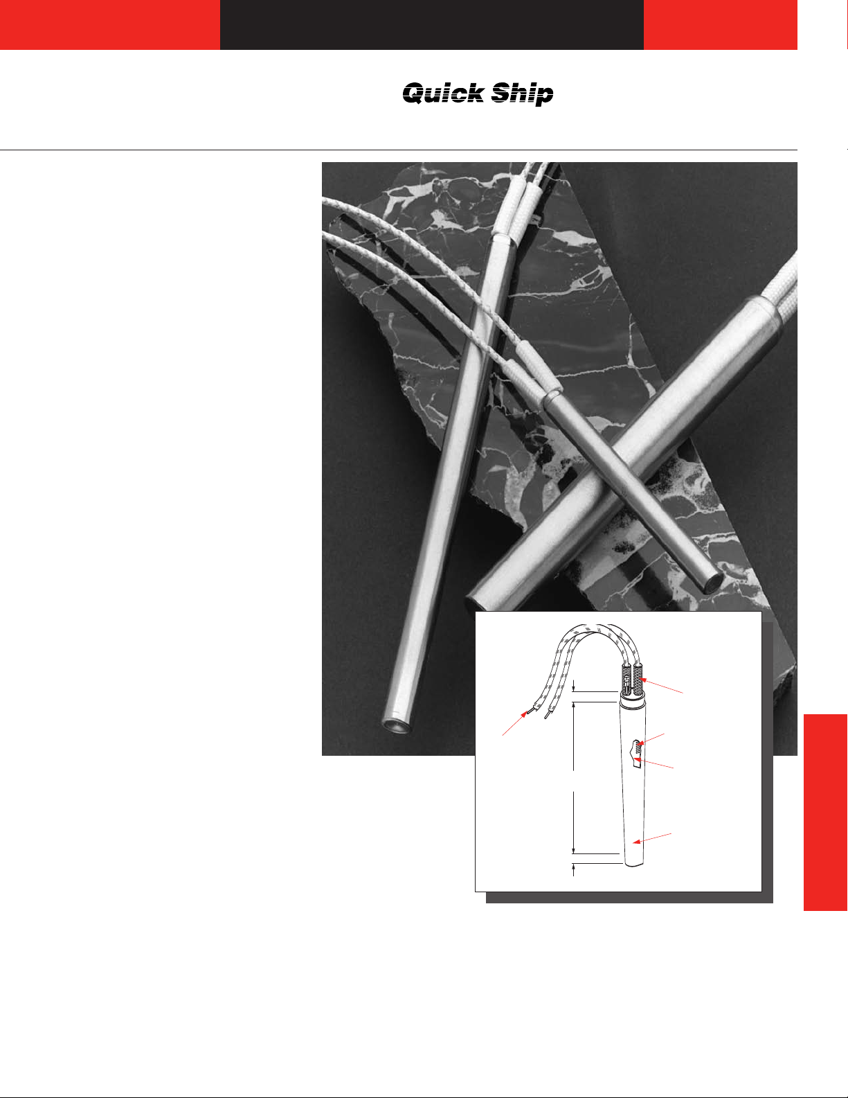
Cartridge Heaters
Metric EB Cartridge
The Watlow EB cartridge heater is a
proven performer like the metric
FIREROD®. That’s because the
same quality materials go into its
construction; MgO insulation, nickelchromium resistance wire,
silicone-fiberglass insulated lead
wires. The only difference is that the
EB cartridge is packaged in a more
economical design. Instead of
having the high watt density
capabilities of a metric FIREROD,
it’s made for medium watt density
applications.
Performance Capabilities
• Part temperatures to 600°C
(1100°F)
• Maximum watt density to
2
30 W/cm
• Maximum voltage to 480VÅ(ac)
Features and Benefits
• Magnesium oxide insulation,
compacted to the proper density,
results in high dielectric strength
and contributes to faster heat-up.
• Nickel-chromium resistance
wire, precisely woundthrough the
heated length, assures even,
efficient distribution of heat to the
sheath.
• Metallurgically-bonded
conductor pins, crimpconnected to the resistance wires,
ensure trouble-free electrical
continuity. This process provides
lead flexibility just 8 mm (5⁄16 inch)
from the end of the heater.
• Flexible stranded wires, with
silicone-fiberglass sleeve, insulate
the wires to temperatures of
250°C (480°F).
• Optional lead end with silicone
rubber seal protects the leads
against moisture and other
contaminants.
(190 W/in2)
FFiibbeerrggllaassss
IInnssuullaatteedd
CCrriimmppeedd oonn
s
LLeeaadds
• VDE component recognition to
230VÅ(ac) according to VDE
0721 part 1/3.78 and part 2/3.78
Section E in connection with VDE
0720 part 1/11.74.
W
Next day shipment on all stock units.
•
d
SSoolliid
CCoonndduuccttoorrs
NNiicckkeell--CChhrroommiiuum
RReessiissttaannccee WWiirre
MMaaggnneessiiuum
OOxxiidde
IInnssuullaattiioon
SSttaaiinnlleesss
SStteeeell SShheeaatth
Applications
• Plastic injection molds, dies and
sealing jaws
Hot melt systems, labeling
•
Industrial and textile
•
manufacturing equipment
s
m
e
m
e
n
s
h
Cartridge Heaters
127
Page 2
Cartridge Heaters
0
Watt Density—W/cm
2
Fit in Hole—mm
1 2 3 4 5 10 15 20 30 40 50
2.5
2.0
1.0
0
.5
0.25
0.1
0.05
0.01
100°C
300°C
400°C
500°C
600°C
200°C
10 20 40 60 80 100 200 300
0.10
0.050
0.020
0.010
0.005
0.002
0.001
Watt Density—W/in
2
Fit in Hole—inches
1100°F
900°F
700°F
500°F
200°F
Metric EB Cartridge
Applications and Technical Data
Continued
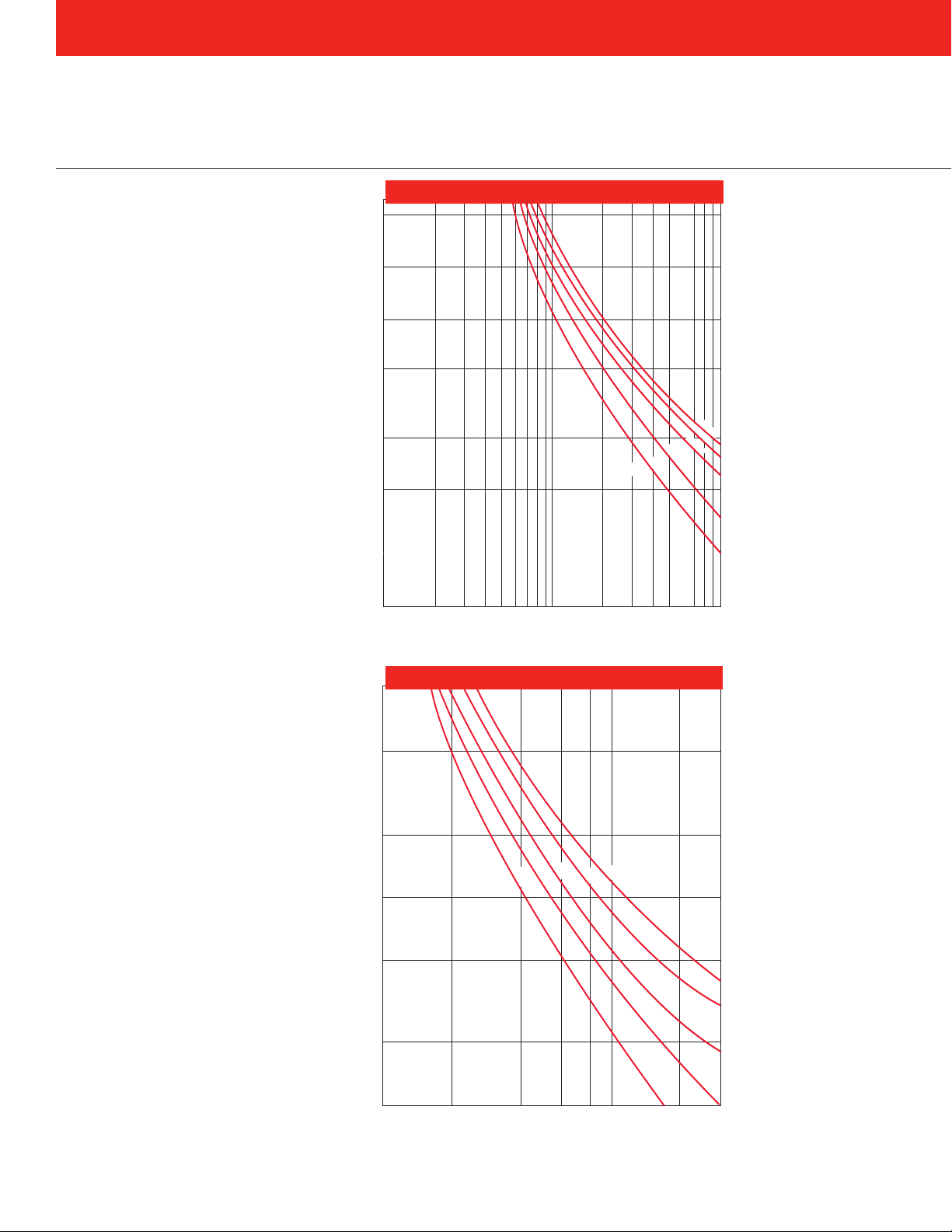
Maximum Allowable Watt Density
Both the Maximum Allowable Watt
Density metric and inch-base charts
will tell you either the hole fit or
recommended watt density in
relationship to part temperature.
Enter the chart with either known
variable, part fit in hole dimension or
watt density. Then find the part
temperature by reading up or over
on the chart. The part temperature
curves shown are measured
13 mm (
mild steel block. For stainless steel
blocks, enter the graph with a fit of
0.04 mm (0.0015 inch) larger than
actual. For aluminum and brass
blocks, enter the graph with a
temperature 55°C (100°F) above
actual block temperature.
On-Off Cycling: On-off cycling
shortens heater life. If the heater
cycles more than once per hour,
multiply the watt density, shown on
the chart, by 0.8 to determine the
maximum allowable watt density for
the application. If the heater cycles
more than once a minute, multiply
by 0.7.
Tolerances
Diameter: -0.02 mm, -0.08 mm
Length: ±
Resistance: +5 percent, -10
Wattage: +10 percent, -5 percent.
1
⁄2 inch) from the heater in a
(-0.0008 inch, -0.0031 inch)
3 percent with
3
(±
⁄32 inch) minimum
percent. Resistance is measured
at room temperature following first
heater operation.
Wattage decreases approximately
5 percent with temperature.
Wattage tolerances are for
heaters at operating temperature.
2.4 mm
±
Maximum Allowable Watt Density
Maximum Allowable Watt Density
128
Page 3
WW AA TT LL OO W
6 mm
(
1
/
4
"
)
As
Specified
B
A
W
Cartridge Heaters
Metric EB Cartridge
Applications and
Technical Data
Continued
Dimensional & Electrical Data
Heater Diameter (mm) 6.5 8 10 12.5 16 20
Nominal Diameter (in) 0.256 0.315 0.394 0.492 0.630 0.787
Maximum Voltage 250 250 250 400 480 480
Crimped-on Leads
Maximum Amps 4.4 4.4 6.7 9.7 23 23
Maximum Wattage @ 230V 1010 1010 1540 2230 5290 5290
Maximum Wattage @ 400V
Swaged-in Leads
Maximum Amps 3.1/4.4
Maximum Wattage @ 230V 710/1010 710/1010 1010 1750/2875 1750/2875 2875
Maximum Wattage @ 400V
➀
— — — 3040/5000 3040/5000 5000
3.1/4.4
➀
4.4 7.6/12.5 ➁7.6/12.5 12.5
3880 9200 9200
➀ On certain lead construction, maximum amperage is 3.1. Please consult Watlow.
➁ On certain lead construction, maximum amperage is 7.6. Please consult Watlow.
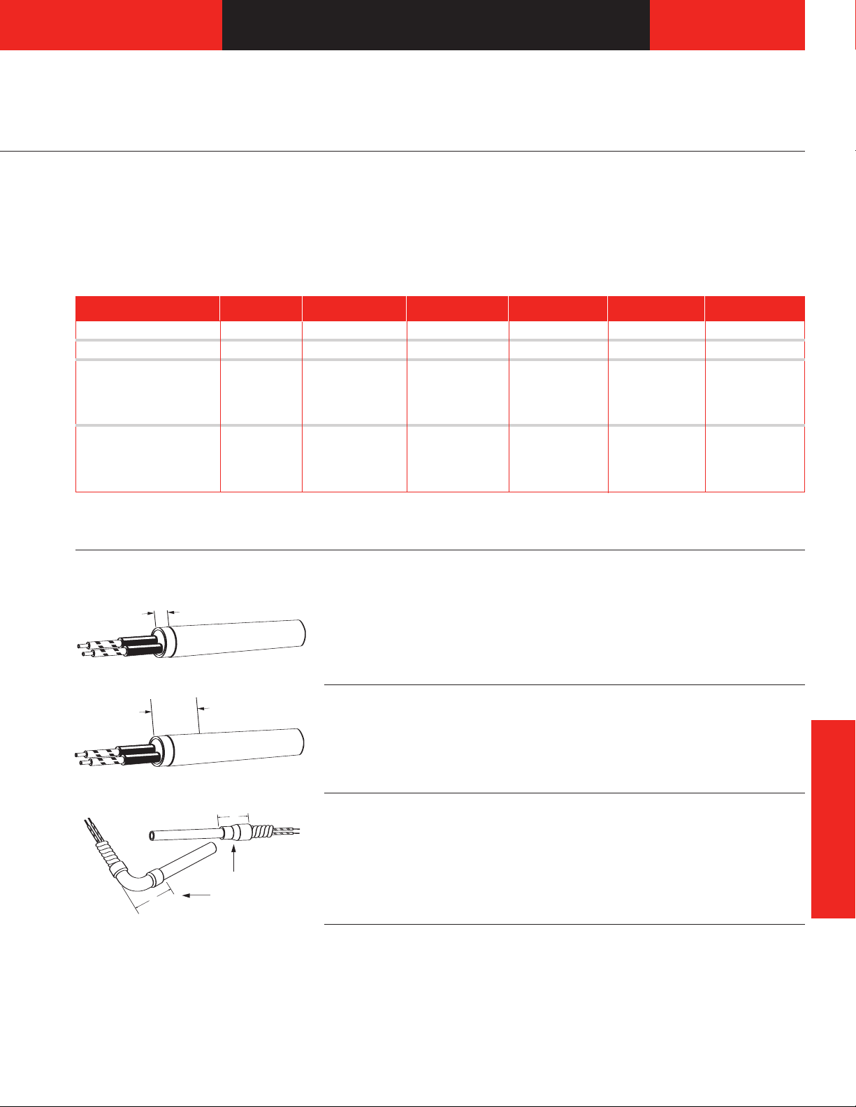
Termination Options
Crimped-on Lead
Crimped-on leads with a 6 mm
(1⁄4 inch) unheated section are
recommended for applications
where the lead wire temperature
does not exceed 250°C (480°F).
No-Heat Zone
An unheated section can be used to
extend the leads safely into a cool
zone in a high temperature
Galvanized Conduit
Flexible galvanized conduit can be
installed over the leads for abrasion
protection. It is attached with either a
Straight
Right Angle
straight or 90 degree elbow copper
coupler. The copper coupler
Unless a longer length is specified,
250 mm (10 inch) leads will be
supplied. To order, request
crimped-on leads and desired lead
length.
application. Leads should be kept
below 250°C (480°F) for maximum
service life. To order, specify no-
heat zone and length of unheated
section.
overlaps the heater sheath by
6 mm (1⁄4 inch). A no-heat section
is required. To order, specify
galvanized conduit, straight or
right angle.
Cartridge Heaters
Stainless Steel Hose
Stainless steel hose also protects
leads against abrasion. It is attached
with a straight or 90 degree elbow
copper coupler. The copper coupler
overlaps the heater sheath by
6 mm (1⁄4 inch).
It can also be swaged-in straight or
silver soldered to the heater sheath
at a right angle. A no-heat section is
required. To order, specify stainless
steel hose, straight or right angle
with copper coupler, straight
swaged-in or right angle silver
soldered.
129
Page 4

25 mm
(1")
Min
6 mm
(
1
/
4
"
)
No-Heat
B
A
Cartridge Heaters
No-Heat
Section
Minimum
No-Heat
Minimum
No-Heat
Metric EB Cartridge
Termination Options
Continued
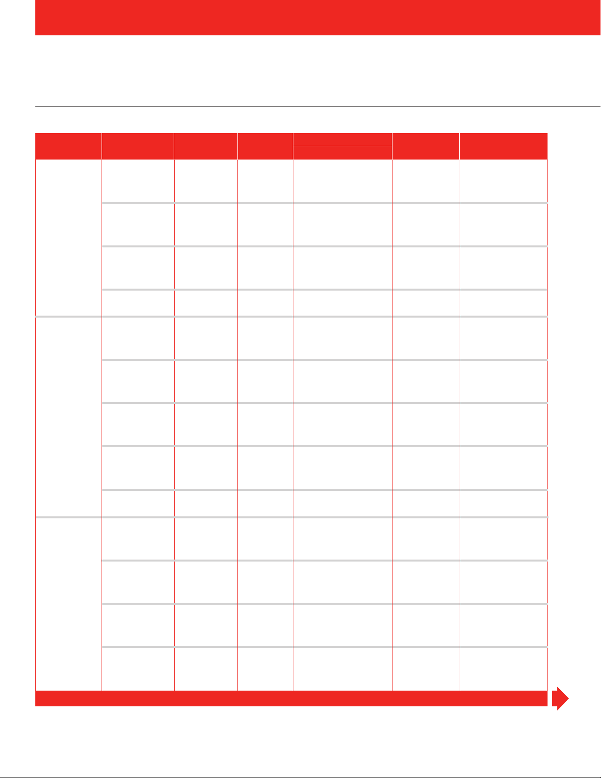
Galvanized Conduit and
Stainless Steel Hose Dimensions
Heater Minimum Dimension Dimension Galvanized Stainless Steel
Diameter No-Heat Length A B Conduit O.D. Hose O.D.
mm mm (inches) mm (inches) mm (inches) mm (inches) mm (inches)
6.5 12 (7⁄16)22(
812(
10 14 (
12.5 16 (
16 19 (
20 22 (
Dimensions are shown for designs with copper coupler only.
7
⁄16)22(
1
⁄2)22(
5
⁄8) 28 (1 1⁄8) 30 (1 3⁄16)14(
3
⁄4) 28 (1 1⁄8) 34 (1 3⁄8)14(
7
⁄8) 29 (1 1⁄8) 36 (1 7⁄16)16(
7
⁄8) 29 (1 1⁄8)10(
7
⁄8) 29 (1 1⁄8)10(
7
⁄8) 29 (1 1⁄8)10(
3
⁄8) 5.6 (3⁄16)
3
⁄8) 6.5 (1⁄4)
3
⁄8) 7.2 (5⁄16)
9
⁄16) 9.5 (3⁄8)
9
⁄16) 12.7 (1⁄2)
5
⁄8) 15.9 (5⁄8)
Brass Stainless Steel
Stainless Steel Braid
Like stainless steel hose, stainless
steel braid also protects against
abrasion. Stainless steel braid is
swaged-in straight or crimped-on to
the heater at a right angle. Metal
Swaged-in Flexible Lead
Swaged-in flexible leads, with a
silicone-fiberglass insulation, are
recommended for applications in
which the leads must be bent at the
exit point from the heater. Unless
longer length is specified, 250 mm
(10 inch) leads are supplied.
Moisture Resistant Seal
Silicone rubber moisture resistant
seals can be provided at the lead
end to virtually seal the heater. This
seal is rated to 230°C (450°F)
continuous operation.
A 25 mm (one inch) no-heat section
is required at the lead end. Solid pin
leads exit through the seal with
Threaded Fitting
Either brass or stainless steel threaded fittings for screw-in mounting can
be added to units that have moisture
resistant seals. Available dimensions
are shown on the Threaded Fittings
braid is recommended when
excellent flexibility with good
physical protection is needed.
A unheated section is required. To
order, specify stainless steel braid,
straight or right angle.
Heaters 140 mm (5 1⁄2 inches) or
shorter generally have a six mm
1
⁄4 inch) no-heat section. Heaters to
(
250 mm (10 inches) require a 25 mm
(one inch) no-heat section. Heaters
greater than 250 mm may require
more than a 25 mm no-heat section.
To order, please specify swaged-in
flexible leads.
crimped-on silicone rubber insulated
lead wires and silicone rubber
sleeves that extend into the seal.
Swaged-in leads are also an option
where flexibility at the lead exit is
required. To order specify, silicone
rubber moisture resistant seal and
either crimped-on or swaged-in
leads
.
charts. To order, please request
brass or stainless steel threaded
fittings and location on the heater.
Note: For liquid immersion
applications, please also specify
heavy weld end disc.
130
Page 5

WW AA TT LL OO W
13 mm (
1
/
2
in.)
No-Heat
W
Cartridge Heaters
Metric EB Cartridge
Termination Options
Continued
DIN Thread Size
Heater Minimum Dimension Dimension Length of
Diameter No-Heat Length Thread Size A B Threaded Section
mm mm (inches) DIN 13 mm (inches) mm (inches) mm (inches)
6.5 16 (5⁄8) M 10 X 1 10 (3⁄8)12(
816(
10 18 (
12.5 19 (
16 20 (
20 22 (
5
⁄8) M 12 X 1 10 (3⁄8)14(
11
⁄16) M 14 X 1.5 11 (7⁄16)17(
3
⁄4) M 16 X 1.5 12 (7⁄16)19(
3
⁄4) M 20 X 1.5 14 (9⁄16)24(
7
⁄8) M 26 X 1.5 15 (9⁄16) 30 (1 3⁄16)10(
NPT Thread Size
Heater Minimum Thread Size Dimension Dimension Length of
Diameter No-Heat Length NPT A B Threaded Section
mm mm (inches) inches mm (inches) mm (inches) mm (inches)
6.5 19 (3⁄4)
8 22 (
10 22 (
12.5 25 (1)
16 28 (1
20 32 (1
7
7
1
⁄8)
⁄8)
⁄8)
1
⁄4)
1
⁄8 13 (1⁄2) 11 (7⁄16) 10 (3⁄8)
1
⁄4 16 (5⁄8) 14 (1⁄2) 13 (1⁄2)
1
⁄4 16 (5⁄8) 14 (1⁄2) 13 (1⁄2)
3
⁄8 19 (3⁄4) 17.5 (11⁄16)15(
1
⁄2 22 (7⁄8) 22 (7⁄8) 16 (5⁄8)
3
⁄4 25 (1) 29 (1 1⁄8)19(
7
⁄16)6(
1
⁄2) 6.5 (1⁄4)
5
⁄8) 6.5 (1⁄4)
3
⁄4) 7.5 (5⁄16)
15
⁄16)9(
1
⁄4)
3
⁄8)
3
⁄8)
9
⁄16)
3
⁄4)
Style A
Style B
Style C
Thermocouple Types
ASTM Conductor Characteristics Temperature Range
Code
J Copper Constantan (Silver Color) -60 to 370 (-75 to 700)
K Chromel
For other ASTM types, contact Watlow.
Positive Negative
®
(Non-Magnetic) Alumel®(Magnetic) -20 to 1260 (0 to 2300)
How to Order
To order stock AB cartridge heaters,
please specify:
• Code number
• Termination options, and length
of leads
Alumel®and Chromel®are registered
trademarks of Hoskins Manufacturing Co.
Internal Thermocouple
Style A is used to evaluate heat
transfer efficiency of an application.
The junction is located in the heater
core to monitor the internal
temperature of the heater.
Style B approximates part
temperature, and is available in all
diameters. The thermocouple
junction can be in contact with the
inside of the heater sheath, located
in the 13 mm (1⁄2 inch) no-heat
For made-to-order units, please
specify:
Diameter
•
Overall length
•
• Watts
Termination options, and length of
•
leads
section anywhere along the heater
length.
Style C is useful in applications
where material flows past the end of
the heater. This junction is embedded
in a special end disc. Type C is
available only on 6.5, 8,10, 12.5 and
16 mm diameter units.
To order, specify internal
thermocouple, Style A, B or C and
thermocouple ASTM Type J, T, K or
E. If not specified, 250 mm (10 inch)
thermocouple leads are supplied.
°C (°F)
Availability
Stock: Next day shipment
Made-to-Order: Shipment within
three weeks
Cartridge Heaters
131
Page 6
Cartridge Heaters
Metric EB Cartridge
Made in Kronau, Germany
Diameter Sheath Length No-Heat Length Watt Density
mm mm (inches) mm Watts W/cm
2
(W/in2) Availability Code No.
6.5 40 (1 9⁄16) 50 9 (58) Stock KEBE0040C001A
40 (1 9⁄16) 75 14 (90) Stock KEBE0040C002A
40 (1 9⁄16) 100 19 (123) Stock KEBE0040C003A
40 (1 9⁄16) 125 24 (155) Stock KEBE0040C004A
40 (1 9⁄16) 150 28 (181) Stock KEBE0040C005A
60 (2 3⁄8) 50 5 (32) Stock KEBE0060C001A
60 (2 3⁄8) 100 11 (71) Stock KEBE0060C002A
60 (2 3⁄8) 150 16 (103) Stock KEBE0060C003A
60 (2 3⁄8) 200 21 (135) Stock KEBE0060C004A
60 (2 3⁄8) 250 27 (174) Stock KEBE0060C005A
80 (3 1⁄8) 100 7 (45) Stock KEBE0080C001A
80 (3 1⁄8) 150 11 (71) Stock KEBE0080C002A
80 (3 1⁄8) 200 15 (97) Stock KEBE0080C003A
80 (3 1⁄8) 300 22 (142) Stock KEBE0080C004A
80 (3 1⁄8) 450 33 (213) Stock KEBE0080C005A
100 (3 15⁄16) 100 6 (39) Stock KEBE0100C001A
100 (3 15⁄16) 200 11 (71) Stock KEBE0100C002A
100 (3
1
5
⁄16) 300 17 (110) Stock KEBE0100C003A
8.0 40 (1 9⁄16) 50 8 (52) Stock KEBF0040C001A
40 (1 9⁄16) 75 11 (71) Stock KEBF0040C002A
40 (1 9⁄16) 100 15 (97) Stock KEBF0040C003A
40 (1 9⁄16) 150 23 (148) Stock KEBF0040C004A
40 (1 9⁄16) 200 31 (200) Stock KEBF0040C005A
60 (2 3⁄8) 75 6 (39) Stock KEBF0060C001A
60 (2 3⁄8) 150 13 (84) Stock KEBF0060C002A
60 (2 3⁄8) 200 17 (110) Stock KEBF0060C003A
60 (2 3⁄8) 250 22 (142) Stock KEBF0060C004A
60 (2 3⁄8) 300 26 (168) Stock KEBF0060C005A
80 (3 1⁄8) 100 6 (39) Stock KEBF0080C001A
80 (3 1⁄8) 200 12 (77) Stock KEBF0080C002A
80 (3 1⁄8) 300 18 (116) Stock KEBF0080C003A
80 (3 1⁄8) 25 400 33 (213) Stock KEBF0080D001A
80 (3 1⁄8) 25 500 41 (265) Stock KEBF0080D002A
5
100 (3
100 (3 15⁄16) 250 12 (77) Stock KEBF0100C002A
100 (3
100 (3 15⁄16) 25 500 29 (187) Stock KEBF0100D002A
100
130
130
1
⁄16) 100 5 (32) Stock KEBF0100C001A
5
1
⁄16) 25 400 23 (148) Stock KEBF0100D001A
5
(3
(5
(5
1
⁄16)
1
⁄8)
1
⁄8)
25
25
25
600
200 8 (52) Stock
350
35
14
(226) Stock
(90)
Stock
KEBF0100D003A
KEBF0130D001A
KEBF0130D002A
130 (5 1⁄8) 25 500 20 (129) Stock KEBF0130D003A
10.0 40 (1 9⁄16) 50 6 (39) Stock KEBG0040C001A
40 (1 9⁄16) 100 12 (77) Stock KEBG0040C002A
40
(1
9
⁄16)
150
18 (116) Stock
KEBG0040C003A
40 (1 9⁄16) 200 24 (155) Stock KEBG0040C004A
40 (1 9⁄16) 250 31 (200) Stock KEBG0040C005A
60 (2 3⁄8) 100 7 (45) Stock KEBG0060C001A
60 (2 3⁄8) 150 10 (65) Stock KEBG0060C002A
60 (2 3⁄8) 200 14 (90) Stock KEBG0060C003A
60 (2 3⁄8) 300 21 (135) Stock KEBG0060C004A
60
80
80
(2
(3
(3
3
⁄8)
1
⁄8)
1
⁄8)
400
100
200
28
5
10
(181)
(32) Stock
(65)
Stock
Stock
KEBG0060C005A
KEBG0080C001A
KEBG0080C002A
80 (3 1⁄8) 300 14 (90) Stock KEBG0080C003A
80 (3 1⁄8) 400 19 (123) Stock KEBG0080C004A
80
100
100 (3
100 (3
100
1
(3
⁄8)
15
(3
⁄16)
5
1
⁄16) 300 11 (71) Stock KEBG0100C002A
5
1
⁄16) 400 15 (97) Stock KEBG0100C003A
15
(3
⁄16)
600
200
500 19 (123) Stock
29 (187) Stock
7
(45)
Stock
KEBG0080C005A
KEBG0100C001A
KEBG0100C004A
100 (3 15⁄16) 25 700 33 (213) Stock KEBG0100D001A
CONTINUED
Note: All stock EB cartridge heaters 230VÅ(ac) and 1000 mm fiberglass insulated swaged-in leads.
132
Page 7

WW AA TT LL OO W
W
Cartridge Heaters
Metric EB Cartridge
D
iameter Sheath Length No-Heat Length Watt Density
mm mm (inches) mm Watts W/cm
10.0 130 (5 1⁄8) 200 5 (32) Stock KEBG0130C001A
12.5 80 (3 1⁄8) 150 6 (39) Stock KEBJ0080C001A
16.0 80 (3 1⁄8) 200 6 (39) Stock KEBL0080C001A
130 (5 1⁄8) 400 11 (71) Stock KEBG0130C002A
130 (5 1⁄8) 25 600 19 (123) Stock KEBG0130D001A
130 (5 1⁄8) 25 800 26 (168) Stock KEBG0130D002A
1
30 (5
160 (6 5⁄16) 25 200 5 (32) Stock KEBG0160D001A
160 (6 5⁄16) 25 500 12 (77) Stock KEBG0160D002A
1
⁄8)
25 1000 32 (206) Stock
160 (6 5⁄16) 25 800 20 (129) Stock KEBG0160D003A
160 (6 5⁄16) 25 1000 25 (161) Stock KEBG0160D004A
160 (6 5⁄16) 25 1200 30 (194) Stock KEBG0160D005A
200 (7 7⁄8) 25 300 6 (39) Stock KEBG0200D001A
200 (7 7⁄8) 25 600 11 (71) Stock KEBG0200D002A
200 (7 7⁄8) 25 1000 19 (123) Stock KEBG0200D003A
200 (7 7⁄8) 25 1200 23 (148) Stock KEBG0200D004A
200 (7 7⁄8) 25 1400 27 (174) Stock KEBG0200D005A
250 (9 7⁄8) 25 400 6 (39) Stock KEBG0250D001A
250 (9 7⁄8) 25 700 10 (65) Stock KEBG0250D002A
250 (9 7⁄8) 25 1000 15 (97) Stock KEBG0250D003A
250 (9 7⁄8) 25 1400 20 (129) Stock KEBG0250D004A
300 (11 13⁄16) 30 500 6 (39) Stock KEBG0300D004A
300 (11 13⁄16) 30 1000 12 (77) Stock KEBG0300D002A
300 (11 13⁄16) 30 1500 18 (116) Stock KEBG0300D003A
80 (3 1⁄8) 300 12 (77) Stock KEBJ0080C003A
80 (3 1⁄8) 400 15 (97) Stock KEBJ0080C004A
80 (3 1⁄8) 500 19 (123) Stock KEBJ0080C002A
80 (3 1⁄8) 700 27 (174) Stock KEBJ0080C005A
100 (3 15⁄16) 200 6 (39) Stock KEBJ0100C001A
100 (3 15⁄16) 400 12 (77) Stock KEBJ0100C002A
100 (3 15⁄16) 600 18 (116) Stock KEBJ0100D003A
100 (3
5
1
⁄16) 800 24 (155) Stock KEBJ0100D004A
100 (3 15⁄16) 25 1000 37 (239) Stock KEBJ0100D001A
130 (5 1⁄8) 250 5 (32) Stock KEBJ0130C001A
130 (5 1⁄8) 500 11 (71) Stock KEBJ0130C002A
130 (5 1⁄8) 25 800 21 (135) Stock KEBJ0130D001A
130 (5 1⁄8) 25 1000 26 (168) Stock KEBJ0130D002A
130 (5 1⁄8) 25 1400 36 (232) Stock KEBJ0130D003A
5
160
160 (6 5⁄16) 25 600 12 (77) Stock KEBJ0160D002A
160
(6
(6
⁄16)
5
⁄16)
25 300 6 (39) Stock
25
1000
160 (6 5⁄16) 25 1400 28 (181) Stock KEBJ0160D004A
160 (6 5⁄16) 25 1700 34 (219) Stock KEBJ0160D005A
200 (7 7⁄8) 25 400 6 (39) Stock KEBJ0200D002A
200 (7 7⁄8) 25 700 11 (71) Stock KEBJ0200D003A
200 (7 7⁄8) 25 1000 15 (97) Stock KEBJ0200D004A
200 (7 7⁄8) 25 1500 23 (148) Stock KEBJ0200D005A
200 (7 7⁄8) 25 2000 30 (194) Stock KEBJ0200D006A
250 (9 7⁄8) 25 500 6 (39) Stock KEBJ0250D001A
250 (9 7⁄8) 25 1000 12 (77) Stock KEBJ0250D002A
250 (9 7⁄8) 25 1500 18 (116) Stock KEBJ0250D003A
250 (9 7⁄8) 25 2000 23 (148) Stock KEBJ0250D004A
300 (11 13⁄16) 30 600 6 (39) Stock KEBJ0300D001A
300
80
80 (3 1⁄8) 600 18 (116) Stock KEBL0080C003A
80
100
100
(11
(3
(3
(3
(3
13
⁄16)
1
⁄8)
1
⁄8)
15
⁄16)
15
⁄16)
30
1500
400
800
300 7 (45) Stock
500
100 (3 15⁄16) 700 16 (103) Stock KEBL0100C003A
100 (3 15⁄16) 25 1000 29 (187) Stock KEBL0100D001A
2
(W/in2) Availability Code No.
20 (129) Stock
15
12
(97)
(77)
Stock
Stock
24 (155) Stock
12
(77) Stock
Made in Kronau, Germany
K
EBG0130D003A
KEBJ0160D001A
KEBJ0160D003A
KEBJ0300D002A
KEBL0080C002A
KEBL0080C004A
KEBL0100C001A
KEBL0100C002A
CONTINUED
Cartridge Heaters
Note: All stock EB cartridge heaters 230VÅ(ac) and 1000 mm fiberglass insulated swaged-in leads.
133
Page 8

Cartridge Heaters
Metric EB Cartridge
Made in Kronau, Germany
Diameter Sheath Length No-Heat Length Watt Density
mm mm (inches) mm Watts W/cm
16.0 130 (5 1⁄8) 25 400 8 (52) Stock KEBL0130D001A
130 (5 1⁄8) 25 600 12 (77) Stock KEBL0130D002A
2
(W/in2) Availability Code No.
130 (5 1⁄8) 25 800 16 (103) Stock KEBL0130D003A
130 (5 1⁄8) 25 1200 24 (155) Stock KEBL0130D004A
160 (6 5⁄16) 25 500 8 (52) Stock KEBL0160D001A
160 (6 5⁄16) 25 700 11 (71) Stock KEBL0160D002A
160 (6 5⁄16) 25 1000 16 (103) Stock KEBL0160D003A
160 (6 5⁄16) 25 1500 23 (148) Stock KEBL0160D004A
160 (6 5⁄16) 25 2000 31 (200) Stock KEBL0160D005A
200 (7 7⁄8) 25 600 7 (45) Stock KEBL0200D001A
200
(7
7
⁄8)
25 1000 12 (77) Stock
200 (7 7⁄8) 25 1500 18 (116) Stock KEBL0200D003A
200 (7 7⁄8) 25 2000 24 (155) Stock KEBL0200D004A
250 (9 7⁄8) 25 700 6 (39) Stock KEBL0250D001A
250
(9
7
⁄8)
25 1500 14 (90) Stock
250 (9 7⁄8) 25 2000 18 (116) Stock KEBL0250D003A
3
300 (11
1
⁄16) 30 1000 8 (52) Stock KEBL0300D001A
300 (11 13⁄16) 30 1500 11 (71) Stock KEBL0300D002A
300 (11 13⁄16) 30 2000 15 (97) Stock KEBL0300D003A
20.0 200 (7 7⁄8) 25 1000 9 (58) Stock KEBN0200D001A
200 (7 7⁄8) 25 1500 14 (90) Stock KEBN0200D002A
200 (7 7⁄8) 25 2000 19 (123) Stock KEBN0200D003A
300 (11 13⁄16) 30 1000 6 (39) Stock KEBN0300D001A
300 (11
3
1
⁄16) 30 1500 9 (58) Stock KEBN0300D002A
300 (11 13⁄16) 30 2500 15 (97) Stock KEBN0300D003A
400 (15 3⁄4) 40 1000 5 (32) Stock KEBN0400D001A
400 (15 3⁄4) 40 2500 11 (71) Stock KEBN0400D002A
400 (15 3⁄4) 40 4000 18 (116) Stock KEBN0400D003A
1
500 (19
500 (19 11⁄16) 50 2500 9 (58) Stock KEBN0500D002A
500 (19
1
⁄16) 50 1000 4 (26) Stock KEBN0500D001A
1
1
⁄16) 50 4000 14 (90) Stock KEBN0500D003A
Note: All stock EB cartridge heaters 230VÅ(ac) and 1000 mm fiberglass insulated swaged-in leads.
KEBL0200D002A
KEBL0250D002A
134
 Loading...