

Page 1

LogicPro
User’s Guide
Watlow Anafaz
314 Westridge Drive
Watsonville, CA 95076
Phone: (831) 724-3800
Fax: (831) 724-0320
Part No. 28002-00. Revision 3.00
September 2000
e
Page 2

Copyright © 2000
Watlow Anafaze
Information in this manual is subject to change without notice. No part of this publication may be
reproduced, stored in a retrieval system, or transmitted in any form without written permission from
Watlow Anafaze.
Anafaze developed package includes licensed proprietary material of Intellution, Inc.
© Intellution, Inc. 1996.
Warranty
Watlow Anafaze, Incorporated warrants that the products furnished under this Agreement will be
free from defects in material and workmanship for a period of three years from the date of shipment. The Customer shall provide notice of any defect to Watlow Anafaze, Incorporated within one
week after the Customer's discovery of such defect. The sole obligation and liability of Watlow
Anafaze, Incorporated under this warranty shall be to repair or replace, at its option and without
cost to the Customer, the defective product or part.
Upon request by Watlow Anafaze, Incorporated, the product or part claimed to be defective shall
immediately be returned at the Customer's expense to Watlow Anafaze, Incorporated. Replaced or
repaired products or parts will be shipped to the Customer at the expense of Watlow Anafaze, Incorporated.
There shall be no warranty or liability for any products or parts that have been subject to misuse,
accident, negligence, failure of electric power or modification by the Customer without the written
approval of Watlow Anafaze, Incorporated. Final determination of warranty eligibility shall be
made by Watlow Anafaze, Incorporated. If a warranty claim is considered invalid for any reason,
the Customer will be charged for services performed and expenses incurred by Watlow Anafaze,
Incorporated in handling and shipping the returned unit.
If replacement parts are supplied or repairs made during the original warranty period, the warranty
period for the replacement or repaired part shall terminate with the termination of the warranty
period of the original product or part.
The foregoing warranty constitutes the sole liability of Watlow Anafaze, Incorporated and the Customer's sole remedy with respect to the products. It is in lieu of all other warranties, liabilities, and
remedies. Except as thus provided, Watlow Anafaze, Inc. disclaims all warranties, express or
implied, including any warranty of merchantability or fitness for a particular purpose.
Please Note
: External safety devices must be used with this equipment.
Page 3

Table of Contents
List of Figures. . . . . . . . . . . . . . . . . . . . . . . . . . . . . . . . . . XI
List of Tables . . . . . . . . . . . . . . . . . . . . . . . . . . . . . . . . . .XV
1 Introduction. . . . . . . . . . . . . . . . . . . . . . . . . . . . . . . . . . 1
This Manual. . . . . . . . . . . . . . . . . . . . . . . . . . . . . . . . . . . . . . . . . . . . . . . . . 1
Where Do I Look?. . . . . . . . . . . . . . . . . . . . . . . . . . . . . . . . . . . . . . . 1
Conventions Used. . . . . . . . . . . . . . . . . . . . . . . . . . . . . . . . . . . . . . . 3
Safety symbols . . . . . . . . . . . . . . . . . . . . . . . . . . . . . . . . . . . . . . . . . . . . . . 4
2 LogicPro Workplace. . . . . . . . . . . . . . . . . . . . . . . . . . . 5
Menu Bar. . . . . . . . . . . . . . . . . . . . . . . . . . . . . . . . . . . . . . . . . . . . . . . . . . . 6
File Menu . . . . . . . . . . . . . . . . . . . . . . . . . . . . . . . . . . . . . . . . . . . . . 7
Edit Menu . . . . . . . . . . . . . . . . . . . . . . . . . . . . . . . . . . . . . . . . . . . . . 8
View Menu . . . . . . . . . . . . . . . . . . . . . . . . . . . . . . . . . . . . . . . . . . . 11
Tools Menu . . . . . . . . . . . . . . . . . . . . . . . . . . . . . . . . . . . . . . . . . . 11
UDFB (User Defined Function Block) Menu . . . . . . . . . . . . . . . . . . 12
Execution Menu . . . . . . . . . . . . . . . . . . . . . . . . . . . . . . . . . . . . . . . 13
Simulation Menu . . . . . . . . . . . . . . . . . . . . . . . . . . . . . . . . . . . . . . 13
Options Menu . . . . . . . . . . . . . . . . . . . . . . . . . . . . . . . . . . . . . . . . . 14
Windows Menu . . . . . . . . . . . . . . . . . . . . . . . . . . . . . . . . . . . . . . . . 16
Help Menu . . . . . . . . . . . . . . . . . . . . . . . . . . . . . . . . . . . . . . . . . . . 17
Status Bar . . . . . . . . . . . . . . . . . . . . . . . . . . . . . . . . . . . . . . . . . . . . . . . . . 18
Toolbars . . . . . . . . . . . . . . . . . . . . . . . . . . . . . . . . . . . . . . . . . . . . . . . . . . 18
Standard Toolbar . . . . . . . . . . . . . . . . . . . . . . . . . . . . . . . . . . . . . . 18
Language Toolbars . . . . . . . . . . . . . . . . . . . . . . . . . . . . . . . . . . . . 20
Using Standard Windows Features . . . . . . . . . . . . . . . . . . . . . . . . . . . . . 22
SFC Actions . . . . . . . . . . . . . . . . . . . . . . . . . . . . . . . . . . . . . . . . . . 22
Ladder Rungs . . . . . . . . . . . . . . . . . . . . . . . . . . . . . . . . . . . . . . . . . 22
Standard Text . . . . . . . . . . . . . . . . . . . . . . . . . . . . . . . . . . . . . . . . . 23
Doc.# 28002-00 Rev 3.00 Watlow Anafaze III
Page 4

Table of Contents LogicPro User’s Guide
3 Projects . . . . . . . . . . . . . . . . . . . . . . . . . . . . . . . . . . . .25
Creating a Project . . . . . . . . . . . . . . . . . . . . . . . . . . . . . . . . . . . . . . . . . . . 26
Opening a Project . . . . . . . . . . . . . . . . . . . . . . . . . . . . . . . . . . . . . . . . . . . 27
Copying Projects . . . . . . . . . . . . . . . . . . . . . . . . . . . . . . . . . . . . . . . . . . . . 28
Backing Up a Project . . . . . . . . . . . . . . . . . . . . . . . . . . . . . . . . . . . . . . . . 29
Closing a Project . . . . . . . . . . . . . . . . . . . . . . . . . . . . . . . . . . . . . . . . . . . . 31
Deleting a Project . . . . . . . . . . . . . . . . . . . . . . . . . . . . . . . . . . . . . . . . . . . 31
4 Resources . . . . . . . . . . . . . . . . . . . . . . . . . . . . . . . . . .33
Creating a Resource . . . . . . . . . . . . . . . . . . . . . . . . . . . . . . . . . . . . . . . . . 33
Editing a Resource . . . . . . . . . . . . . . . . . . . . . . . . . . . . . . . . . . . . . . . . . . 36
Copying Resources . . . . . . . . . . . . . . . . . . . . . . . . . . . . . . . . . . . . . . . . . . 36
Resource Backup . . . . . . . . . . . . . . . . . . . . . . . . . . . . . . . . . . . . . . . . . . . 37
Deleting a Resource . . . . . . . . . . . . . . . . . . . . . . . . . . . . . . . . . . . . . . . . . 38
Opening a Resource . . . . . . . . . . . . . . . . . . . . . . . . . . . . . . . . . . . . . . . . . 39
5 Programs . . . . . . . . . . . . . . . . . . . . . . . . . . . . . . . . . . . 41
Creating a New Program . . . . . . . . . . . . . . . . . . . . . . . . . . . . . . . . . . . . . 41
Opening a Program . . . . . . . . . . . . . . . . . . . . . . . . . . . . . . . . . . . . . . . . . 42
Saving a Program . . . . . . . . . . . . . . . . . . . . . . . . . . . . . . . . . . . . . . . . . . . 43
Closing a Program . . . . . . . . . . . . . . . . . . . . . . . . . . . . . . . . . . . . . . . . . . 43
Copying Programs . . . . . . . . . . . . . . . . . . . . . . . . . . . . . . . . . . . . . . . . . . 44
Saving a Program with a New Name (Save As) . . . . . . . . . . . . . . . . . . . .45
Backing Up a Program . . . . . . . . . . . . . . . . . . . . . . . . . . . . . . . . . . . . . . . 45
Deleting a Program . . . . . . . . . . . . . . . . . . . . . . . . . . . . . . . . . . . . . . . . . . 47
6 Variables . . . . . . . . . . . . . . . . . . . . . . . . . . . . . . . . . . .49
Naming Conventions . . . . . . . . . . . . . . . . . . . . . . . . . . . . . . . . . . . . . . . . . 49
Retentive Variables . . . . . . . . . . . . . . . . . . . . . . . . . . . . . . . . . . . . . . . . . . 50
System Variables . . . . . . . . . . . . . . . . . . . . . . . . . . . . . . . . . . . . . . . . . . . 50
Project Variables . . . . . . . . . . . . . . . . . . . . . . . . . . . . . . . . . . . . . . . . . . . . 51
Adding a Project Variable . . . . . . . . . . . . . . . . . . . . . . . . . . . . . . . . 52
Editing a Project Variable . . . . . . . . . . . . . . . . . . . . . . . . . . . . . . . . 53
Deleting a Project Variable . . . . . . . . . . . . . . . . . . . . . . . . . . . . . . . 54
Cloning a Project Variable . . . . . . . . . . . . . . . . . . . . . . . . . . . . . . . 55
Resource Variables . . . . . . . . . . . . . . . . . . . . . . . . . . . . . . . . . . . . . . . . . . 56
Adding a Resource/Program Variable . . . . . . . . . . . . . . . . . . . . . . 56
Editing a Resource/Program Variable . . . . . . . . . . . . . . . . . . . . . . 59
Deleting Resource/Program Variables . . . . . . . . . . . . . . . . . . . . . . 60
Cloning a Resource or Program Variable . . . . . . . . . . . . . . . . . . . . 61
Program Variables . . . . . . . . . . . . . . . . . . . . . . . . . . . . . . . . . . . . . . . . . . 61
Finding and Replacing a Variable In a Program . . . . . . . . . . . . . . . . . . . . 62
Using the Find Command . . . . . . . . . . . . . . . . . . . . . . . . . . . . . . . . 62
Using the Replace Command . . . . . . . . . . . . . . . . . . . . . . . . . . . . . 64
Import/Export . . . . . . . . . . . . . . . . . . . . . . . . . . . . . . . . . . . . . . . . . . . . . . 65
Importing an ASCII file . . . . . . . . . . . . . . . . . . . . . . . . . . . . . . . . . . 65
Verifying the Import Operation . . . . . . . . . . . . . . . . . . . . . . . . . . . . 67
Creating or Editing an ASCII file . . . . . . . . . . . . . . . . . . . . . . . . . . . 67
Exporting an ASCII file . . . . . . . . . . . . . . . . . . . . . . . . . . . . . . . . . . 70
Verifying the Export Operation . . . . . . . . . . . . . . . . . . . . . . . . . . . . 70
IV Watlow Anafaze Doc.# 28002-00 Rev 3.00
Page 5

LogicPro User’s Guide Table of Contents
7 Sequential Function Charts. . . . . . . . . . . . . . . . . . . . 71
About SFC . . . . . . . . . . . . . . . . . . . . . . . . . . . . . . . . . . . . . . . . . . . . . . . . 71
Using SFCs in LogicPro . . . . . . . . . . . . . . . . . . . . . . . . . . . . . . . . . . . . . . 71
SFC Toolbar . . . . . . . . . . . . . . . . . . . . . . . . . . . . . . . . . . . . . . . . . . . . . . . 72
Selector . . . . . . . . . . . . . . . . . . . . . . . . . . . . . . . . . . . . . . . . . . . . . 73
Origin Step . . . . . . . . . . . . . . . . . . . . . . . . . . . . . . . . . . . . . . . . . . . 73
Step . . . . . . . . . . . . . . . . . . . . . . . . . . . . . . . . . . . . . . . . . . . . . . . . 73
Simultaneous Transition . . . . . . . . . . . . . . . . . . . . . . . . . . . . . . . . . 74
Loop Back . . . . . . . . . . . . . . . . . . . . . . . . . . . . . . . . . . . . . . . . . . . 77
Action . . . . . . . . . . . . . . . . . . . . . . . . . . . . . . . . . . . . . . . . . . . . . . . 78
Comments . . . . . . . . . . . . . . . . . . . . . . . . . . . . . . . . . . . . . . . . . . . 79
Cross Reference . . . . . . . . . . . . . . . . . . . . . . . . . . . . . . . . . . . . . . 79
8 Ladder Diagrams . . . . . . . . . . . . . . . . . . . . . . . . . . . . 81
Ladder Toolbar . . . . . . . . . . . . . . . . . . . . . . . . . . . . . . . . . . . . . . . . . . . . . 82
Selector. . . . . . . . . . . . . . . . . . . . . . . . . . . . . . . . . . . . . . . . . . . . . . 83
Normally Open Contact . . . . . . . . . . . . . . . . . . . . . . . . . . . . . . . . . 83
Normally Closed Contact . . . . . . . . . . . . . . . . . . . . . . . . . . . . . . . . 84
Off To On Transitional Contact . . . . . . . . . . . . . . . . . . . . . . . . . . . 84
On To Off Transitional Contact . . . . . . . . . . . . . . . . . . . . . . . . . . . 85
Normal Coil . . . . . . . . . . . . . . . . . . . . . . . . . . . . . . . . . . . . . . . . . . 85
Latched Coil . . . . . . . . . . . . . . . . . . . . . . . . . . . . . . . . . . . . . . . . . . 85
Unlatched Coil . . . . . . . . . . . . . . . . . . . . . . . . . . . . . . . . . . . . . . . . 86
Function Block . . . . . . . . . . . . . . . . . . . . . . . . . . . . . . . . . . . . . . . . 86
Comments . . . . . . . . . . . . . . . . . . . . . . . . . . . . . . . . . . . . . . . . . . . 86
Cross Reference . . . . . . . . . . . . . . . . . . . . . . . . . . . . . . . . . . . . . . 87
Viewing the Grid . . . . . . . . . . . . . . . . . . . . . . . . . . . . . . . . . . . . . . . 87
Creating and Editing Ladder Diagrams . . . . . . . . . . . . . . . . . . . . . . . . . . 88
Inserting Rungs . . . . . . . . . . . . . . . . . . . . . . . . . . . . . . . . . . . . . . . 88
Inserting Elements . . . . . . . . . . . . . . . . . . . . . . . . . . . . . . . . . . . . . 88
Inserting Function Blocks . . . . . . . . . . . . . . . . . . . . . . . . . . . . . . . . 89
Connecting Function Blocks to Other Ladder Elements . . . . . . . . 90
Inserting Parallel (Or) Branches . . . . . . . . . . . . . . . . . . . . . . . . . . . 93
Inserting Multiple Output Coil branches . . . . . . . . . . . . . . . . . . . . . 96
Inserting Elements From the Left Power Rail . . . . . . . . . . . . . . . . . 97
Cutting Rungs . . . . . . . . . . . . . . . . . . . . . . . . . . . . . . . . . . . . . . . . 98
Copying Rungs . . . . . . . . . . . . . . . . . . . . . . . . . . . . . . . . . . . . . . . . 99
Pasting Rungs . . . . . . . . . . . . . . . . . . . . . . . . . . . . . . . . . . . . . . . . 99
Deleting Elements . . . . . . . . . . . . . . . . . . . . . . . . . . . . . . . . . . . . 100
Moving Elements . . . . . . . . . . . . . . . . . . . . . . . . . . . . . . . . . . . . . 100
Assigning Labels to Rungs . . . . . . . . . . . . . . . . . . . . . . . . . . . . . . 100
Assigning Variable Names . . . . . . . . . . . . . . . . . . . . . . . . . . . . . . . . . . . 101
Naming and Assigning Variables to Function Blocks . . . . . . . . . . . . . . . 102
Adding Comments to Ladder Diagrams . . . . . . . . . . . . . . . . . . . . . . . . . 104
Hiding Rung Comments . . . . . . . . . . . . . . . . . . . . . . . . . . . . . . . . 104
Doc.# 28002-00 Rev 3.00 Watlow Anafaze V
Page 6

Table of Contents LogicPro User’s Guide
9 Function Block Diagrams. . . . . . . . . . . . . . . . . . . . .105
FBD Toolbar . . . . . . . . . . . . . . . . . . . . . . . . . . . . . . . . . . . . . . . . . . . . . . 105
Selector . . . . . . . . . . . . . . . . . . . . . . . . . . . . . . . . . . . . . . . . . . . . 106
Straight Connections . . . . . . . . . . . . . . . . . . . . . . . . . . . . . . . . . .106
Inverted Connections . . . . . . . . . . . . . . . . . . . . . . . . . . . . . . . . . . 106
Variables . . . . . . . . . . . . . . . . . . . . . . . . . . . . . . . . . . . . . . . . . . . 107
Function Blocks . . . . . . . . . . . . . . . . . . . . . . . . . . . . . . . . . . . . . . 107
Cross Reference . . . . . . . . . . . . . . . . . . . . . . . . . . . . . . . . . . . . . . 107
Creating an FBD Program . . . . . . . . . . . . . . . . . . . . . . . . . . . . . . . . . . . 107
Inserting Function Blocks . . . . . . . . . . . . . . . . . . . . . . . . . . . . . . . 108
Inserting Variable Elements . . . . . . . . . . . . . . . . . . . . . . . . . . . . . 109
Connecting Inputs and Outputs . . . . . . . . . . . . . . . . . . . . . . . . . . 109
Assigning Variables to Variable Elements . . . . . . . . . . . . . . . . . . 110
Assigning Names and Execution Orders to
Function Blocks . . . . . . . . . . . . . . . . . . . . . . . . . . . . . . . . . 111
Cutting, Copying, Pasting, and Deleting . . . . . . . . . . . . . . . . . . . . 112
10 Function Blocks . . . . . . . . . . . . . . . . . . . . . . . . . . . .115
Standard Function Blocks . . . . . . . . . . . . . . . . . . . . . . . . . . . . . . . . . . . . 115
Timing and Counting Elements . . . . . . . . . . . . . . . . . . . . . . . . . . . . . . . . 115
Counter Up (CTU) . . . . . . . . . . . . . . . . . . . . . . . . . . . . . . . . . . . . 116
Counter Down (CTD) . . . . . . . . . . . . . . . . . . . . . . . . . . . . . . . . . . 117
Counter Up Down (CTUD) . . . . . . . . . . . . . . . . . . . . . . . . . . . . . . 119
Timer Pulse (TP) . . . . . . . . . . . . . . . . . . . . . . . . . . . . . . . . . . . . . 121
Timer On-Delay (TON) . . . . . . . . . . . . . . . . . . . . . . . . . . . . . . . . . 123
Timer Off-Delay (TOF) . . . . . . . . . . . . . . . . . . . . . . . . . . . . . . . . . 124
Comparison . . . . . . . . . . . . . . . . . . . . . . . . . . . . . . . . . . . . . . . . . . . . . . . 126
Greater Than (GT) . . . . . . . . . . . . . . . . . . . . . . . . . . . . . . . . . . . . 126
Less Than (LT) . . . . . . . . . . . . . . . . . . . . . . . . . . . . . . . . . . . . . . . 127
Equal To (EQ) . . . . . . . . . . . . . . . . . . . . . . . . . . . . . . . . . . . . . . . . 128
Arithmetic . . . . . . . . . . . . . . . . . . . . . . . . . . . . . . . . . . . . . . . . . . . . . . . . 130
Add (ADD) . . . . . . . . . . . . . . . . . . . . . . . . . . . . . . . . . . . . . . . . . . 130
Subtract (SUB) . . . . . . . . . . . . . . . . . . . . . . . . . . . . . . . . . . . . . . . 131
Multiply (MULT) . . . . . . . . . . . . . . . . . . . . . . . . . . . . . . . . . . . . . . 132
Divide (DIV) . . . . . . . . . . . . . . . . . . . . . . . . . . . . . . . . . . . . . . . . . 133
Data Manipulation . . . . . . . . . . . . . . . . . . . . . . . . . . . . . . . . . . . . . . . . . . 135
First In - First Out (FIFO) . . . . . . . . . . . . . . . . . . . . . . . . . . . . . . . 135
Last In - First Out (LIFO) . . . . . . . . . . . . . . . . . . . . . . . . . . . . . . . 137
Bit Shift (SL) . . . . . . . . . . . . . . . . . . . . . . . . . . . . . . . . . . . . . . . . . 140
Scan Time Counter (SCAN) . . . . . . . . . . . . . . . . . . . . . . . . . . . . . 142
Move (MOVE) . . . . . . . . . . . . . . . . . . . . . . . . . . . . . . . . . . . . . . . . 143
Scale (SCL) . . . . . . . . . . . . . . . . . . . . . . . . . . . . . . . . . . . . . . . . . 144
Real Number Function Blocks . . . . . . . . . . . . . . . . . . . . . . . . . . . . . . . . 145
Real Greater Than (RGT) . . . . . . . . . . . . . . . . . . . . . . . . . . . . . . . 145
Real Less Than (RLT) . . . . . . . . . . . . . . . . . . . . . . . . . . . . . . . . . 146
Real Equal To (REQ) . . . . . . . . . . . . . . . . . . . . . . . . . . . . . . . . . . 147
Real Add (RADD) . . . . . . . . . . . . . . . . . . . . . . . . . . . . . . . . . . . . . 148
Real Subtract (RSUB) . . . . . . . . . . . . . . . . . . . . . . . . . . . . . . . . . 149
Real Multiply (RMUL) . . . . . . . . . . . . . . . . . . . . . . . . . . . . . . . . . . 151
Real Divide (RDIV) . . . . . . . . . . . . . . . . . . . . . . . . . . . . . . . . . . . . 152
Real Move (RMOV) . . . . . . . . . . . . . . . . . . . . . . . . . . . . . . . . . . . 153
Integer To Real (ITOR) . . . . . . . . . . . . . . . . . . . . . . . . . . . . . . . . . 154
VI Watlow Anafaze Doc.# 28002-00 Rev 3.00
Page 7

LogicPro User’s Guide Table of Contents
Real to Integer (RTOI) . . . . . . . . . . . . . . . . . . . . . . . . . . . . . . . . . 155
Square Root (SRT) . . . . . . . . . . . . . . . . . . . . . . . . . . . . . . . . . . . 155
Logical . . . . . . . . . . . . . . . . . . . . . . . . . . . . . . . . . . . . . . . . . . . . . . . . . . 157
Logical And (AND) . . . . . . . . . . . . . . . . . . . . . . . . . . . . . . . . . . . . 157
Logical Or (OR) . . . . . . . . . . . . . . . . . . . . . . . . . . . . . . . . . . . . . . 157
Vendor Provided Function Blocks . . . . . . . . . . . . . . . . . . . . . . . . . . . . . . 158
Comparison (CMP) . . . . . . . . . . . . . . . . . . . . . . . . . . . . . . . . . . . 158
Calculation (CALC) . . . . . . . . . . . . . . . . . . . . . . . . . . . . . . . . . . . 159
Jump (JMP) . . . . . . . . . . . . . . . . . . . . . . . . . . . . . . . . . . . . . . . . . 161
InterLock (IL) . . . . . . . . . . . . . . . . . . . . . . . . . . . . . . . . . . . . . . . . 162
InterLock-Clear (ILC) . . . . . . . . . . . . . . . . . . . . . . . . . . . . . . . . . . 162
Rotation (RROT/LROT) . . . . . . . . . . . . . . . . . . . . . . . . . . . . . . . . 163
Shift (RSFT/LSFT) . . . . . . . . . . . . . . . . . . . . . . . . . . . . . . . . . . . 164
Negation (NEG) 1 . . . . . . . . . . . . . . . . . . . . . . . . . . . . . . . . . . . . . 165
11 User Defined Function Blocks. . . . . . . . . . . . . . . . . 167
Overview . . . . . . . . . . . . . . . . . . . . . . . . . . . . . . . . . . . . . . . . . . . . . . . . . 167
Getting Started . . . . . . . . . . . . . . . . . . . . . . . . . . . . . . . . . . . . . . . . . . . . 167
Defining a New or Editing an Existing UDFB . . . . . . . . . . . . . . . . . . . . . 168
In’s, Out's and Internals . . . . . . . . . . . . . . . . . . . . . . . . . . . . . . . . 169
UDFB Files . . . . . . . . . . . . . . . . . . . . . . . . . . . . . . . . . . . . . . . . . . . . . . . 172
Compiling and Building a Library . . . . . . . . . . . . . . . . . . . . . . . . . . . . . . 174
UDFB in Simulation . . . . . . . . . . . . . . . . . . . . . . . . . . . . . . . . . . . . . . . . 175
Working with UDFB Files . . . . . . . . . . . . . . . . . . . . . . . . . . . . . . . . . . . . 177
Editing UDFB Files . . . . . . . . . . . . . . . . . . . . . . . . . . . . . . . . . . . . 177
Opening UDFB Files . . . . . . . . . . . . . . . . . . . . . . . . . . . . . . . . . . 177
Closing UDFB Files . . . . . . . . . . . . . . . . . . . . . . . . . . . . . . . . . . . 177
Saving UDFB Files . . . . . . . . . . . . . . . . . . . . . . . . . . . . . . . . . . . . 178
Deleting UDFBs . . . . . . . . . . . . . . . . . . . . . . . . . . . . . . . . . . . . . . 178
UDFB Tutorial . . . . . . . . . . . . . . . . . . . . . . . . . . . . . . . . . . . . . . . . . . . . . 179
12 Input/Output Drivers. . . . . . . . . . . . . . . . . . . . . . . . . 185
Variable Types . . . . . . . . . . . . . . . . . . . . . . . . . . . . . . . . . . . . . . . . . . . . 186
Input/Output . . . . . . . . . . . . . . . . . . . . . . . . . . . . . . . . . . . . . . . . . . . . . . 187
IO Size . . . . . . . . . . . . . . . . . . . . . . . . . . . . . . . . . . . . . . . . . . . . . . . . . . 187
PPC-2000 IO Drivers . . . . . . . . . . . . . . . . . . . . . . . . . . . . . . . . . . . . . . . 188
IO Driver Choice . . . . . . . . . . . . . . . . . . . . . . . . . . . . . . . . . . . . . . 188
IO Physical Addresses . . . . . . . . . . . . . . . . . . . . . . . . . . . . . . . . . 188
Using the IO Drivers . . . . . . . . . . . . . . . . . . . . . . . . . . . . . . . . . . . 192
CPC400 IO Drivers . . . . . . . . . . . . . . . . . . . . . . . . . . . . . . . . . . . . . . . . . 208
IO Driver Choice . . . . . . . . . . . . . . . . . . . . . . . . . . . . . . . . . . . . . . 208
IO Physical Addresses . . . . . . . . . . . . . . . . . . . . . . . . . . . . . . . . . 208
Using the IO Drivers . . . . . . . . . . . . . . . . . . . . . . . . . . . . . . . . . . . 210
13 Compiler Setup . . . . . . . . . . . . . . . . . . . . . . . . . . . . . 221
Setting up the Compiler . . . . . . . . . . . . . . . . . . . . . . . . . . . . . . . . . . . . . 221
Doc.# 28002-00 Rev 3.00 Watlow Anafaze VII
Page 8

Table of Contents LogicPro User’s Guide
14 Simulation . . . . . . . . . . . . . . . . . . . . . . . . . . . . . . . . .225
Building a Program for Simulation . . . . . . . . . . . . . . . . . . . . . . . . . . . . . 226
Using the Simulation Tools . . . . . . . . . . . . . . . . . . . . . . . . . . . . . . . . . . . 227
Simulation Setup . . . . . . . . . . . . . . . . . . . . . . . . . . . . . . . . . . . . . . 228
Timer Ticks . . . . . . . . . . . . . . . . . . . . . . . . . . . . . . . . . . . . . . . . . . 229
Increment Simulation Timer Ticks . . . . . . . . . . . . . . . . . . . . . . . . . 230
Scan Simulation Logic. . . . . . . . . . . . . . . . . . . . . . . . . . . . . . . . . . 230
Number of Scan . . . . . . . . . . . . . . . . . . . . . . . . . . . . . . . . . . . . . . 230
Resetting the Simulation . . . . . . . . . . . . . . . . . . . . . . . . . . . . . . . . 231
Change Simulation Variables . . . . . . . . . . . . . . . . . . . . . . . . . . . . 231
Change Simulation Constants . . . . . . . . . . . . . . . . . . . . . . . . . . . 232
Viewing Individual Steps and Actions within a Simulation . . . . . . . . . . . 233
Closing the Simulation . . . . . . . . . . . . . . . . . . . . . . . . . . . . . . . . . . . . . . 233
15 Downloading and Monitoring. . . . . . . . . . . . . . . . . .235
Executable . . . . . . . . . . . . . . . . . . . . . . . . . . . . . . . . . . . . . . . . . . . . . . . 235
Downloading to a controller through an RS-232 Port . . . . . . . . . . 235
Monitoring a Program . . . . . . . . . . . . . . . . . . . . . . . . . . . . . . . . . . . . . . . 237
Monitoring Sequential Function Charts . . . . . . . . . . . . . . . . . . . . 239
Monitoring Ladder Diagrams . . . . . . . . . . . . . . . . . . . . . . . . . . . . 239
Monitoring Function Block Diagrams . . . . . . . . . . . . . . . . . . . . . . 240
Forcing I/O . . . . . . . . . . . . . . . . . . . . . . . . . . . . . . . . . . . . . . . . . . . . . . . 240
Variable Watch . . . . . . . . . . . . . . . . . . . . . . . . . . . . . . . . . . . . . . . . . . . . 241
Configuring Variable Watch . . . . . . . . . . . . . . . . . . . . . . . . . . . . . 242
Selecting and Viewing Variables . . . . . . . . . . . . . . . . . . . . . . . . .242
Changing the Value of a Variable . . . . . . . . . . . . . . . . . . . . . . . . . 243
Forcing Variables . . . . . . . . . . . . . . . . . . . . . . . . . . . . . . . . . . . . . 243
Watch Grid View . . . . . . . . . . . . . . . . . . . . . . . . . . . . . . . . . . . . . . 244
On-Line Constant Changes . . . . . . . . . . . . . . . . . . . . . . . . . . . . . . . . . . 246
16 Cross-Referencing . . . . . . . . . . . . . . . . . . . . . . . . . .249
Using Cross-Referencing . . . . . . . . . . . . . . . . . . . . . . . . . . . . . . . . . . . . 249
SFC On-line Cross-Reference . . . . . . . . . . . . . . . . . . . . . . . . . . . 249
Ladder On-line Cross-Reference . . . . . . . . . . . . . . . . . . . . . . . . . 250
Function Block Diagram On-line Cross-Reference . . . . . . . . . . . . 251
Cross-Reference Output . . . . . . . . . . . . . . . . . . . . . . . . . . . . . . . . . . . . . 251
Output Printing . . . . . . . . . . . . . . . . . . . . . . . . . . . . . . . . . . . . . . . 253
Report Setup . . . . . . . . . . . . . . . . . . . . . . . . . . . . . . . . . . . . . . . . 254
Variables Setup . . . . . . . . . . . . . . . . . . . . . . . . . . . . . . . . . . . . . .255
Ladder Setup . . . . . . . . . . . . . . . . . . . . . . . . . . . . . . . . . . . . . . . . 255
SFC Setup . . . . . . . . . . . . . . . . . . . . . . . . . . . . . . . . . . . . . . . . . . 256
FBD Setup . . . . . . . . . . . . . . . . . . . . . . . . . . . . . . . . . . . . . . . . . . 257
VIII Watlow Anafaze Doc.# 28002-00 Rev 3.00
Page 9

LogicPro User’s Guide Table of Contents
17 Dynamic Data Exchange . . . . . . . . . . . . . . . . . . . . . 259
How to Access a Remote Item . . . . . . . . . . . . . . . . . . . . . . . . . . . . . . . . 259
Installation . . . . . . . . . . . . . . . . . . . . . . . . . . . . . . . . . . . . . . . . . . . . . . . 260
Starting the LogicPro DDE Application . . . . . . . . . . . . . . . . . . . . . . . . . . 260
Configuration . . . . . . . . . . . . . . . . . . . . . . . . . . . . . . . . . . . . . . . . . . . . . 260
Creating the Application FPR File . . . . . . . . . . . . . . . . . . . . . . . . . . . . . 261
Topics . . . . . . . . . . . . . . . . . . . . . . . . . . . . . . . . . . . . . . . . . . . . . . . . . . . 262
Creating A New Topic . . . . . . . . . . . . . . . . . . . . . . . . . . . . . . . . . 262
Open a Topic . . . . . . . . . . . . . . . . . . . . . . . . . . . . . . . . . . . . . . . . 263
Close a Topic . . . . . . . . . . . . . . . . . . . . . . . . . . . . . . . . . . . . . . . . 263
Modify a Topic . . . . . . . . . . . . . . . . . . . . . . . . . . . . . . . . . . . . . . . 263
Delete a Topic . . . . . . . . . . . . . . . . . . . . . . . . . . . . . . . . . . . . . . . 263
Item Point Naming . . . . . . . . . . . . . . . . . . . . . . . . . . . . . . . . . . . . . . . . . 264
Finding The Available Item Names . . . . . . . . . . . . . . . . . . . . . . . 264
Excel Spreadsheet DDE Sample . . . . . . . . . . . . . . . . . . . . . . . . . . . . . . 264
Setting Up Excel to Read . . . . . . . . . . . . . . . . . . . . . . . . . . . . . . . 266
Glossary . . . . . . . . . . . . . . . . . . . . . . . . . . . . . . . . . . . . . 269
Doc.# 28002-00 Rev 3.00 Watlow Anafaze IX
Page 10

Table of Contents LogicPro User’s Guide
X Watlow Anafaze Doc.# 28002-00 Rev 3.00
Page 11

List of Figures
1 Introduction. . . . . . . . . . . . . . . . . . . . . . . . . . . . . . . . . . . . . . . . . 1
2 LogicPro Workplace. . . . . . . . . . . . . . . . . . . . . . . . . . . . . . . . . . 5
Figure 2.1—The LogicPro Workplace . . . . . . . . . . . . . . . . . . . . . . . . . . . . . . . . . . . . . . 6
Figure 2.2—Two Views of the LogicPro Standard toolbar, showing
various active buttons . . . . . . . . . . . . . . . . . . . . . . . . . . . . . . . . . . . . . . . . 18
3 Projects . . . . . . . . . . . . . . . . . . . . . . . . . . . . . . . . . . . . . . . . . . . 25
Figure 3.1—Projects Hierarchy . . . . . . . . . . . . . . . . . . . . . . . . . . . . . . . . . . . . . . . . . . . 25
Figure 3.2—New Project Dialog Box . . . . . . . . . . . . . . . . . . . . . . . . . . . . . . . . . . . . . . 26
Figure 3.3—Open Project Dialog Box . . . . . . . . . . . . . . . . . . . . . . . . . . . . . . . . . . . . . 27
Figure 3.4—Rebuild Project List Dialog Box . . . . . . . . . . . . . . . . . . . . . . . . . . . . . . . . . 28
Figure 3.5—Copy Project Dialog Box . . . . . . . . . . . . . . . . . . . . . . . . . . . . . . . . . . . . . . 30
Figure 3.6—Delete Project Dialog Box . . . . . . . . . . . . . . . . . . . . . . . . . . . . . . . . . . . . . 32
4 Resources . . . . . . . . . . . . . . . . . . . . . . . . . . . . . . . . . . . . . . . . . 33
Figure 4.1—New Resource Dialog Box. . . . . . . . . . . . . . . . . . . . . . . . . . . . . . . . . . . . . 33
Figure 4.2—PPC-2000 Attributes Dialog Box . . . . . . . . . . . . . . . . . . . . . . . . . . . . . . . . 34
Figure 4.3—Edit Resource Dialog Box . . . . . . . . . . . . . . . . . . . . . . . . . . . . . . . . . . . . . 36
Figure 4.4—Copy Resource Dialog Box . . . . . . . . . . . . . . . . . . . . . . . . . . . . . . . . . . . . 38
Figure 4.5—Delete Resource Dialog Box . . . . . . . . . . . . . . . . . . . . . . . . . . . . . . . . . . . 39
Figure 4.6—Open Resource Dialog Box. . . . . . . . . . . . . . . . . . . . . . . . . . . . . . . . . . . . 39
5 Programs. . . . . . . . . . . . . . . . . . . . . . . . . . . . . . . . . . . . . . . . . . 41
Figure 5.1—New Program Dialog Box . . . . . . . . . . . . . . . . . . . . . . . . . . . . . . . . . . . . 42
Figure 5.2—Open Program Dialog Box. . . . . . . . . . . . . . . . . . . . . . . . . . . . . . . . . . . . . 43
Figure 5.3—Verify Dialog Box . . . . . . . . . . . . . . . . . . . . . . . . . . . . . . . . . . . . . . . . . . . 44
Figure 5.4—Copy Program Dialog Box . . . . . . . . . . . . . . . . . . . . . . . . . . . . . . . . . . . . 46
Figure 5.5—Delete Program Dialog Box . . . . . . . . . . . . . . . . . . . . . . . . . . . . . . . . . . . 47
6 Variables . . . . . . . . . . . . . . . . . . . . . . . . . . . . . . . . . . . . . . . . . . 49
Figure 6.1—Project Variables Dialog Box. . . . . . . . . . . . . . . . . . . . . . . . . . . . . . . . . . . 51
Figure 6.2—Add Project Variable . . . . . . . . . . . . . . . . . . . . . . . . . . . . . . . . . . . . . . . . . 52
Figure 6.3—Edit Project Variable Dialog Box . . . . . . . . . . . . . . . . . . . . . . . . . . . . . . . . 54
Figure 6.4—Resource Variable Dialog Box. . . . . . . . . . . . . . . . . . . . . . . . . . . . . . . . . . 57
Figure 6.5—Program Variable Dialog Box . . . . . . . . . . . . . . . . . . . . . . . . . . . . . . . . . . 57
Doc.# 28002-00 Rev 3.00 Watlow Anafaze XI
Page 12

List of Figures LogicPro User’s Guide
Figure 6.6—Add Resource Variable Dialog Box . . . . . . . . . . . . . . . . . . . . . . . . . . . . . .58
Figure 6.7—Program Variables Dialog Box. . . . . . . . . . . . . . . . . . . . . . . . . . . . . . . . . .62
Figure 6.8—Find Variable . . . . . . . . . . . . . . . . . . . . . . . . . . . . . . . . . . . . . . . . . . . . . . .63
7 Sequential Function Charts . . . . . . . . . . . . . . . . . . . . . . . . . . .71
Figure 7.1—Simultaneous Transition. . . . . . . . . . . . . . . . . . . . . . . . . . . . . . . . . . . . . . .74
Figure 7.2—Parallel and / or Single Transitions . . . . . . . . . . . . . . . . . . . . . . . . . . . . . .75
Figure 7.3—Simultaneous Transition Conditions. . . . . . . . . . . . . . . . . . . . . . . . . . . . . .75
8 Ladder Diagrams. . . . . . . . . . . . . . . . . . . . . . . . . . . . . . . . . . . .81
Figure 8.1—Element without Handles . . . . . . . . . . . . . . . . . . . . . . . . . . . . . . . . . . . . . .83
Figure 8.2—Selected Element with Handles . . . . . . . . . . . . . . . . . . . . . . . . . . . . . . . . .83
Figure 8.3—Rungs with Multiple Branches . . . . . . . . . . . . . . . . . . . . . . . . . . . . . . . . . .88
Figure 8.4—Function Block Dialog Box. . . . . . . . . . . . . . . . . . . . . . . . . . . . . . . . . . . . .89
Figure 8.5—Rung Before Adding a Function Block. . . . . . . . . . . . . . . . . . . . . . . . . . . .90
Figure 8.6—Rung With a Function Block Added . . . . . . . . . . . . . . . . . . . . . . . . . . . . . .90
Figure 8.7—Ladder Diagram Before Elements Are Added to Function Block. . . . . . . .91
Figure 8.8—Ladder Diagram After Elements Are Added to Function Block . . . . . . . . .91
Figure 8.9—Inserting an Input Element on a Function Block . . . . . . . . . . . . . . . . . . . .92
Figure 8.10—Element Inserted Between Left Power Rail and Second Input Bit. . . . . .92
Figure 8.11—Connecting an Element to a Function Block’s Output . . . . . . . . . . . . . . .93
Figure 8.12—Function Block After Connecting Output Element . . . . . . . . . . . . . . . . . .93
Figure 8.13—Adding the Parallel Branch. . . . . . . . . . . . . . . . . . . . . . . . . . . . . . . . . . . .94
Figure 8.14—After Adding the Parallel Branch . . . . . . . . . . . . . . . . . . . . . . . . . . . . . . .94
Figure 8.15—Adding Another Branch . . . . . . . . . . . . . . . . . . . . . . . . . . . . . . . . . . . . . .95
Figure 8.16—Branch Added . . . . . . . . . . . . . . . . . . . . . . . . . . . . . . . . . . . . . . . . . . . . .95
Figure 8.17—Creating a New Parallel Branch from the Left Power Rail . . . . . . . . . . .96
Figure 8.18—After Creating a New Parallel Branch from the Left Power Rail. . . . . . . .96
Figure 8.19—Before Creating Multiple Output Coil Branches . . . . . . . . . . . . . . . . . . .97
Figure 8.20—After Creating Multiple Output Coil Branches . . . . . . . . . . . . . . . . . . . . 97
Figure 8.21—Multiple Output Coil Branches
after the Top Coil is Removed . . . . . . . . . . . . . . . . . . . . . . . . . . . . . . . .97
Figure 8.22—Adding an Extension from the Left Power Rail. . . . . . . . . . . . . . . . . . . . 98
Figure 8.23—After Adding an Extension from the Left Power Rail . . . . . . . . . . . . . . . .98
Figure 8.24—Variables Dialog Box . . . . . . . . . . . . . . . . . . . . . . . . . . . . . . . . . . . . . . .101
Figure 8.25—Assign Function Block Symbolic Input/Output Dialog Box. . . . . . . . . . .103
Figure 8.26—Symbolic Name on Function Block in a Ladder Diagram Program . . . .103
Figure 8.27—Rung Comment Dialog Box . . . . . . . . . . . . . . . . . . . . . . . . . . . . . . . . . .104
9 Function Block Diagrams. . . . . . . . . . . . . . . . . . . . . . . . . . . .105
Figure 9.1—Function Block Dialog Box. . . . . . . . . . . . . . . . . . . . . . . . . . . . . . . . . . . .108
Figure 9.2—Placed Function Blocks . . . . . . . . . . . . . . . . . . . . . . . . . . . . . . . . . . . . . .109
Figure 9.3—Symbolic Name on Function Block in a FBD program . . . . . . . . . . . . . .110
Figure 9.4—Assign Name to Function Block Dialog Box . . . . . . . . . . . . . . . . . . . . . .111
Figure 9.5—Execution Order in FBD . . . . . . . . . . . . . . . . . . . . . . . . . . . . . . . . . . . . .112
Figure 9.6—Function Blocks in FBD with Handles . . . . . . . . . . . . . . . . . . . . . . . . . . .113
Figure 9.7—Pasted Function Block in FBD . . . . . . . . . . . . . . . . . . . . . . . . . . . . . . . . .113
Figure 9.8—Function Block Before Deletion, With Handles . . . . . . . . . . . . . . . . . . . .114
Figure 9.9—Function Block After Deletion. . . . . . . . . . . . . . . . . . . . . . . . . . . . . . . . . .114
XII Watlow Anafaze Doc.#28002-00 Rev 3.00
Page 13

LogicPro User’s Guide List of Figures
10 Function Blocks . . . . . . . . . . . . . . . . . . . . . . . . . . . . . . . . . . . 115
Figure 10.1—Counter Up Function Block . . . . . . . . . . . . . . . . . . . . . . . . . . . . . . . . . . 116
Figure 10.2—Assign Function Block Symbolic Input/Output Dialog Box. . . . . . . . . . . 117
Figure 10.3—Counter Down Function Block. . . . . . . . . . . . . . . . . . . . . . . . . . . . . . . . 118
Figure 10.4—Counter Up Down Function Block . . . . . . . . . . . . . . . . . . . . . . . . . . . . . 119
Figure 10.5—Timer Pulse Function Block. . . . . . . . . . . . . . . . . . . . . . . . . . . . . . . . . . 121
Figure 10.6—Relationship between the Input and Output of TP Function Block . . . .123
Figure 10.7—Timer On-Delay Function Block . . . . . . . . . . . . . . . . . . . . . . . . . . . . . . 123
Figure 10.8—Relationship Between Inputs and Outputs of TON Function Block . . . .124
Figure 10.9—Timer Off-Delay Function Block. . . . . . . . . . . . . . . . . . . . . . . . . . . . . . . 125
Figure 10.10—Relationship Between Inputs and Outputs of TOF Function Block . . . 126
Figure 10.11—Greater Than Function Block. . . . . . . . . . . . . . . . . . . . . . . . . . . . . . . . 126
Figure 10.12—Less Than Function Block . . . . . . . . . . . . . . . . . . . . . . . . . . . . . . . . . .128
Figure 10.13—Equal To Function Block . . . . . . . . . . . . . . . . . . . . . . . . . . . . . . . . . . . 129
Figure 10.14—ADD Function Block . . . . . . . . . . . . . . . . . . . . . . . . . . . . . . . . . . . . . . 130
Figure 10.15—Subtract Function Block. . . . . . . . . . . . . . . . . . . . . . . . . . . . . . . . . . . . 131
Figure 10.16—Multiply Function Block . . . . . . . . . . . . . . . . . . . . . . . . . . . . . . . . . . . . 132
Figure 10.17—Divide Function Block . . . . . . . . . . . . . . . . . . . . . . . . . . . . . . . . . . . . . 134
Figure 10.18—First In - First Out Function Block . . . . . . . . . . . . . . . . . . . . . . . . . . . . 135
Figure 10.19—Last In - First Out Function Block . . . . . . . . . . . . . . . . . . . . . . . . . . . . 138
Figure 10.20—Bit Shift Function Block . . . . . . . . . . . . . . . . . . . . . . . . . . . . . . . . . . . . 140
Figure 10.21—Example of How Bits Shift Through the SL Function Block. . . . . . . . . 141
Figure 10.22—Scan Time Counter Function Block . . . . . . . . . . . . . . . . . . . . . . . . . . 142
Figure 10.23— Move Function Block . . . . . . . . . . . . . . . . . . . . . . . . . . . . . . . . . . . . . 143
Figure 10.24— Scale Function Block . . . . . . . . . . . . . . . . . . . . . . . . . . . . . . . . . . . . . 144
Figure 10.25—ROUT as a function of INP . . . . . . . . . . . . . . . . . . . . . . . . . . . . . . . . . 145
Figure 10.26— Real Greater Than Function Block . . . . . . . . . . . . . . . . . . . . . . . . . . 146
Figure 10.27— Real Less Than Function Block . . . . . . . . . . . . . . . . . . . . . . . . . . . . . 147
Figure 10.28— Real Equal To Function Block . . . . . . . . . . . . . . . . . . . . . . . . . . . . . . 148
Figure 10.29— Real Add Function Block . . . . . . . . . . . . . . . . . . . . . . . . . . . . . . . . . . 149
Figure 10.30— Real Subtract Function Block . . . . . . . . . . . . . . . . . . . . . . . . . . . . . . . 150
Figure 10.31— Real Multiply Function Block. . . . . . . . . . . . . . . . . . . . . . . . . . . . . . . . 151
Figure 10.32— Real Divide Function Block. . . . . . . . . . . . . . . . . . . . . . . . . . . . . . . . . 152
Figure 10.33— Real Move Function Block . . . . . . . . . . . . . . . . . . . . . . . . . . . . . . . . . 153
Figure 10.34— Integer to Real Function Block . . . . . . . . . . . . . . . . . . . . . . . . . . . . . . 154
Figure 10.35— Real to Integer Function Block . . . . . . . . . . . . . . . . . . . . . . . . . . . . . . 155
Figure 10.36— Square Root Function Block. . . . . . . . . . . . . . . . . . . . . . . . . . . . . . . . 156
Figure 10.37— The Logical AND Function Block . . . . . . . . . . . . . . . . . . . . . . . . . . . . 157
Figure 10.38— The Logical OR Function Block . . . . . . . . . . . . . . . . . . . . . . . . . . . . . 157
Figure 10.39—Vendor Provided Function Block diagram . . . . . . . . . . . . . . . . . . . . . . 158
Figure 10.40— The Comparison Function Block. . . . . . . . . . . . . . . . . . . . . . . . . . . . . 159
Figure 10.41— The Calculation Function Block . . . . . . . . . . . . . . . . . . . . . . . . . . . . . 160
Figure 10.42— The Jump Function Block . . . . . . . . . . . . . . . . . . . . . . . . . . . . . . . . . 161
Figure 10.43— The InterLock Function Block. . . . . . . . . . . . . . . . . . . . . . . . . . . . . . . 162
Figure 10.44— The InterLock Clear Function Block . . . . . . . . . . . . . . . . . . . . . . . . . . 162
Figure 10.45— The Right and Left Rotation Function Blocks . . . . . . . . . . . . . . . . . . .163
Figure 10.46— The Right and Left Shift Function Blocks . . . . . . . . . . . . . . . . . . . . . . 164
Figure 10.47— The Negation Function Block . . . . . . . . . . . . . . . . . . . . . . . . . . . . . . . 165
11 User Defined Function Blocks. . . . . . . . . . . . . . . . . . . . . . . . 167
Figure 11.1—New UDFB Dialog Box . . . . . . . . . . . . . . . . . . . . . . . . . . . . . . . . . . . 169
Figure 11.2—Add Symbol Definition Dialog Box. . . . . . . . . . . . . . . . . . . . . . . . . . . . . 171
Doc.# 28002-00 Rev 3.00 Watlow Anafaze XIII
Page 14

List of Figures LogicPro User’s Guide
Figure 11.3—Edit Symbol Definition Dialog Box . . . . . . . . . . . . . . . . . . . . . . . . . . . . .171
Figure 11.4—Build UDFB Library for Execution . . . . . . . . . . . . . . . . . . . . . . . . . . . . .174
Figure 11.5—Build UDFB Library for Simulation Dialog Box. . . . . . . . . . . . . . . . . . . .176
Figure 11.6—Open User Defined Function Block Dialog Box . . . . . . . . . . . . . . . . . . .177
Figure 11.7—Delete User Defined Function Block Dialog Box . . . . . . . . . . . . . . . . . .178
Figure 11.8—ADD1 Function Block . . . . . . . . . . . . . . . . . . . . . . . . . . . . . . . . . . . . . .180
12 Input/Output Drivers . . . . . . . . . . . . . . . . . . . . . . . . . . . . . . . .185
13 Compiler Setup . . . . . . . . . . . . . . . . . . . . . . . . . . . . . . . . . . . .221
Figure 13.1—Simulation Compiler. . . . . . . . . . . . . . . . . . . . . . . . . . . . . . . . . . . . . . . .221
Figure 13.2—Compiler Paths. . . . . . . . . . . . . . . . . . . . . . . . . . . . . . . . . . . . . . . . . . . .222
Figure 13.3—Select Borland Compiler . . . . . . . . . . . . . . . . . . . . . . . . . . . . . . . . . . . .222
14 Simulation . . . . . . . . . . . . . . . . . . . . . . . . . . . . . . . . . . . . . . . .225
Figure 14.1—Compiler Dialog Box . . . . . . . . . . . . . . . . . . . . . . . . . . . . . . . . . . . . . . .227
Figure 14.2—Borland C++ Compiler DOS window . . . . . . . . . . . . . . . . . . . . . . . . . . .227
Figure 14.3—Simulation Setup Dialog Box . . . . . . . . . . . . . . . . . . . . . . . . . . . . . . . . .229
Figure 14.4—Change Variables Dialog Box . . . . . . . . . . . . . . . . . . . . . . . . . . . . . . . .231
Figure 14.5—On-Line Function Block Constant Change. . . . . . . . . . . . . . . . . . . . . . .232
15 Downloading and Monitoring. . . . . . . . . . . . . . . . . . . . . . . . .235
Figure 15.1—Downloading . . . . . . . . . . . . . . . . . . . . . . . . . . . . . . . . . . . . . . . . . . . . .237
Figure 15.2—LogicPro Monitoring Window . . . . . . . . . . . . . . . . . . . . . . . . . . . . . . . . .238
Figure 15.3—Active Step in an SFC . . . . . . . . . . . . . . . . . . . . . . . . . . . . . . . . . . . . . .239
Figure 15.4—Monitoring Ladder Diagrams . . . . . . . . . . . . . . . . . . . . . . . . . . . . . . . . .240
Figure 15.5—Force - Clear IO Dialog Box. . . . . . . . . . . . . . . . . . . . . . . . . . . . . . . . . .241
Figure 15.6—The Watch Grid in the Variable Watch Window. . . . . . . . . . . . . . . . . . .245
Figure 15.7—On-Line Function Block Variables Change Dialog Box . . . . . . . . . . . . .247
16 Cross-Referencing . . . . . . . . . . . . . . . . . . . . . . . . . . . . . . . . .249
Figure 16.1—The Cross-Reference Pointer . . . . . . . . . . . . . . . . . . . . . . . . . . . . . . . .250
Figure 16.2—Print Dialog Box . . . . . . . . . . . . . . . . . . . . . . . . . . . . . . . . . . . . . . . . . . .253
Figure 16.3—Report Setup Dialog Box . . . . . . . . . . . . . . . . . . . . . . . . . . . . . . . . . . . .254
Figure 16.4—Variable Setup Dialog Box. . . . . . . . . . . . . . . . . . . . . . . . . . . . . . . . . . .255
Figure 16.5—Ladder Setup Dialog Box. . . . . . . . . . . . . . . . . . . . . . . . . . . . . . . . . . . .256
Figure 16.6—SFC Setup Dialog Box. . . . . . . . . . . . . . . . . . . . . . . . . . . . . . . . . . . . . .256
Figure 16.7—FBD Setup Dialog Box. . . . . . . . . . . . . . . . . . . . . . . . . . . . . . . . . . . . . .257
17 Dynamic Data Exchange. . . . . . . . . . . . . . . . . . . . . . . . . . . . .259
Figure 17.1—Example 1 . . . . . . . . . . . . . . . . . . . . . . . . . . . . . . . . . . . . . . . . . . . . . . .265
Figure 17.2—Spreadsheet Example . . . . . . . . . . . . . . . . . . . . . . . . . . . . . . . . . . . . . .266
XIV Watlow Anafaze Doc.#28002-00 Rev 3.00
Page 15

List of Tables
1 Introduction. . . . . . . . . . . . . . . . . . . . . . . . . . . . . . . . . . 1
Table 1.1—Chapter Descriptions . . . . . . . . . . . . . . . . . . . . . . . . . . . . . . . . 2
Table 1.2—Conventions Used. . . . . . . . . . . . . . . . . . . . . . . . . . . . . . . . . . . 4
2 LogicPro Workplace. . . . . . . . . . . . . . . . . . . . . . . . . . . 5
Table 2.1—The File Menu. . . . . . . . . . . . . . . . . . . . . . . . . . . . . . . . . . . . . . 7
Table 2.2—The Edit Menu. . . . . . . . . . . . . . . . . . . . . . . . . . . . . . . . . . . . . . 9
Table 2.3—The View Menu. . . . . . . . . . . . . . . . . . . . . . . . . . . . . . . . . . . . 11
Table 2.4—The Tools Menu . . . . . . . . . . . . . . . . . . . . . . . . . . . . . . . . . . . 12
Table 2.5—The UDFB Menu. . . . . . . . . . . . . . . . . . . . . . . . . . . . . . . . . . . 13
Table 2.6—The Execution Menu. . . . . . . . . . . . . . . . . . . . . . . . . . . . . . . . 13
Table 2.7—The Simulation Menu . . . . . . . . . . . . . . . . . . . . . . . . . . . . . . . 14
Table 2.8—The Options Menu . . . . . . . . . . . . . . . . . . . . . . . . . . . . . . . . . 14
Table 2.9—The Windows Menu . . . . . . . . . . . . . . . . . . . . . . . . . . . . . . . . 16
Table 2.10—Levels of Help. . . . . . . . . . . . . . . . . . . . . . . . . . . . . . . . . . . . 17
Table 2.11—Help Menu Options. . . . . . . . . . . . . . . . . . . . . . . . . . . . . . . . 17
Table 2.12—Toolbar Definitions . . . . . . . . . . . . . . . . . . . . . . . . . . . . . . . . 18
Table 2.13—The SFC Toolbar . . . . . . . . . . . . . . . . . . . . . . . . . . . . . . . . . 20
Table 2.14—The Ladder Toolbar . . . . . . . . . . . . . . . . . . . . . . . . . . . . . . . 21
Table 2.15—The FBD Toolbar . . . . . . . . . . . . . . . . . . . . . . . . . . . . . . . . . 21
3 Projects . . . . . . . . . . . . . . . . . . . . . . . . . . . . . . . . . . . . 25
4 Resources . . . . . . . . . . . . . . . . . . . . . . . . . . . . . . . . . . 33
5 Programs. . . . . . . . . . . . . . . . . . . . . . . . . . . . . . . . . . . 41
6 Variables . . . . . . . . . . . . . . . . . . . . . . . . . . . . . . . . . . . 49
Table 6.1—File Format Specification of Import/Export . . . . . . . . . . . . . . . 68
Table 6.2—Selected Explanations of the Example Import/Export File . . . 69
7 Sequential Function Charts. . . . . . . . . . . . . . . . . . . . 71
Table 7.1—The SFC Toolbar . . . . . . . . . . . . . . . . . . . . . . . . . . . . . . . . . . 72
Table 7.2—Transition Condition Expressions . . . . . . . . . . . . . . . . . . . . . . 76
Doc.# 28002-00 Rev 3.00 Watlow Anafaze XV
Page 16

List of Tables LogicPro User’s Guide
8 Ladder Diagrams. . . . . . . . . . . . . . . . . . . . . . . . . . . . .81
Table 8.1—Ladder Diagrams Toolbar . . . . . . . . . . . . . . . . . . . . . . . . . . . . 82
9 Function Block Diagrams. . . . . . . . . . . . . . . . . . . . .105
Table 9.1—FBD Toolbar Functions . . . . . . . . . . . . . . . . . . . . . . . . . . . . . 106
10 Function Blocks . . . . . . . . . . . . . . . . . . . . . . . . . . . .115
Table 10.1—Symbol Operation . . . . . . . . . . . . . . . . . . . . . . . . . . . . . . . . 160
11 User Defined Function Blocks . . . . . . . . . . . . . . . . .167
12 Input/Output Drivers . . . . . . . . . . . . . . . . . . . . . . . . .185
Table 12.1—Variable Types . . . . . . . . . . . . . . . . . . . . . . . . . . . . . . . . . . 186
Table 12.2—Input and Output . . . . . . . . . . . . . . . . . . . . . . . . . . . . . . . . . 187
Table 12.3—
Table 12.4—Data Accessed by the IO Drivers . . . . . . . . . . . . . . . . . . . . 188
Table 12.5—Categories of IO Drivers . . . . . . . . . . . . . . . . . . . . . . . . . . . 189
Table 12.6—Address Syntax for Module Specific Drivers. . . . . . . . . . . . 189
Table 12.7—I/O Type Digit in IO Physical Address. . . . . . . . . . . . . . . . . 190
Table 12.8—Addresses Used with Parameter Specific IO Drives. . . . . .190
Table 12.9—Address Syntax for Database Driver. . . . . . . . . . . . . . . . . 191
Table 12.10—Data Accessed by the IO Drivers . . . . . . . . . . . . . . . . . . . 208
Table 12.11—Categories of IO Drivers . . . . . . . . . . . . . . . . . . . . . . . . . . 208
Table 12.12—Addresses Used for Hardware Specific Drivers . . . . . . . .209
Table 12.13—Addresses Used with Parameter Specific IO Drivers . . . . 209
Table 12.14—Address Syntax for Database Driver. . . . . . . . . . . . . . . . 210
IO Sizes Used with IO Drivers . . . . . . . . . . . . . . . . . . . . . . 187
13 Compiler Setup . . . . . . . . . . . . . . . . . . . . . . . . . . . . .221
14 Simulation . . . . . . . . . . . . . . . . . . . . . . . . . . . . . . . . .225
Table 14.1—Simulation Tools . . . . . . . . . . . . . . . . . . . . . . . . . . . . . . . . 228
15 Downloading and Monitoring. . . . . . . . . . . . . . . . . .235
Table 15.1—The Columns in the Watch Grid . . . . . . . . . . . . . . . . . . . . . 245
16 Cross-Referencing . . . . . . . . . . . . . . . . . . . . . . . . . .249
17 Dynamic Data Exchange. . . . . . . . . . . . . . . . . . . . . . 259
XVI Watlow Anafaze Doc.# 28002-00 Rev 3.00
Page 17

1
Introduction
This Manual
Where Do I Look?
Welcome to
programming environment that allows you to create and
debug programs, and manage real-time distributed or
embedded control systems.
graphically write a “C” program without knowing the
language.
LogicPro
programming languages like
These languages have evolved into proven, effective solutions
for automation and control projects.
If it relates to
these covers with few exceptions.
Take some time familiarizing yourself with the layout and
design of this manual. Refer to
complete listing of the section numbers and titles along with a
general overview of what you can expect to find in each
chapter.
LogicPro
use the familiar conventions of typical graphical
LogicPro
, a Microsoft Windows based graphical
LogicPro
Grafcet, Ladder Logic,
, you should be able to find it between
allows you to
Table 1.1 on page 2
etc.
for a
Doc.# 28002-00 Rev 3.00 Watlow Anafaze 1
Page 18

Chapter 1: Introduction LogicPro User’s Guide
Table 1.1 Chapter Descriptions
Chapter Title Description
1 Introduction
2
3 Projects
4 Resources
5 Programs
6 Variables
7
The LogicPro
Workplace
Sequential
Function Charts
Introduction and general
information.
The LogicPro Workplace
and screen layout.
Creating, using, and
changing LogicPro
Projects.
Creating, using, and
changing LogicPro
Resources.
Creating, using, and
changing LogicPro Programs within a resource.
Creating, using, and
changing LogicPro Variables within projects,
resources, and programs.
Explanation of the tools
available for programming in the SFC (Sequential Function Chart)
language in LogicPro .
8 Ladder Diagrams
9
10 Function Blocks
Function Block
Diagrams
Explanation of the tools
available for programming in the Ladder Diagram (LD) language in
LogicPro .
Explanation of the tools
available for programming in the FBD (Function
Block Diagram) language
in LogicPro .
Information on Standard
IEC 1131-3 and Vendor
provided function blocks:
specific information on
many of the most common function blocks, how
to use function blocks in
your programs, and where
to look for more information.
2 Watlow Anafaze Doc.# 28002-00 Rev 3.00
Page 19

LogicPro User’s Guide Chapter 1: Introduction
Chapter Title Description
11
12 I/O Drivers
13 Compilers
14 Simulation
15
16 Cross-Referencing
17
User Defined
Function Blocks
Downloading and
Monitoring
Dynamic Data
Exchange
Information about creating and using User
Defined Function Blocks.
Information on input/output drivers, examples,
and where to look for
more information.
Information about using
the Borland C++ compiler.
Information on the simulator function of LogicPro ,
specifically, how to use it.
How to download a program to your hardware
and monitor it once it’s
been downloaded.
How to use the CrossReferencing functions of
LogicPro .
Using DDE for accessing
and editing LogicPro data.
Conventions Used
Definitions of the terms,
Glossary
Index
acronyms, and expressions used in this manual.
Where to find the information you’re looking for.
To help improve the readability of this manual we use
different fonts and styles to identify specific actions you will
initiate in the program.
Table 1.2 on page 4 lists the conventions used as well as a
brief description of each.
Doc.# 28002-00 Rev 3.00 Watlow Anafaze 3
Page 20

Chapter 1: Introduction LogicPro User’s Guide
Table 1.2 Conventions Used
Convention Explanation
Italics
Capitalization
Bold Sans Serif
[Bold San Serif in
Square Brackets]
<Bold serif text in
Angular Brackets>
ALL CAPS,
SANS SERIF,
MONOSPACE
Unbolded,
serif,
monospace
Unbolded Sans Serif
Indicates references to Chapters,
sections, Figures and Tables .
Indicates the proper name of an element of LogicPro .
Indicates LogicPro menu headings
or options.
Indicates the name of a button or
tool on the screen.
Indicates a specific key or combination of keys on your keyboard.
Indicates text as it appears in function blocks in the program editor.
Indicates a filename or code as it
appears in the User-Defined Function Block programming windows , or
text as it appears in ASCII files.
Sample cross-reference print out.
Safety symbols
∫
WARNING!
ç
CAUTION!
NOTE!
These symbols are used throughout this manual:
Indicates a potentially hazardous situation which,
if not avoided, could result in death or serious injury.
Indicates a potentially hazardous situation which,
if not avoided, could result in minor or moderate
injury or property damage.
Indicates pertinent information or an item that
may be useful to document or label for later reference.
4 Watlow Anafaze Doc.# 28002-00 Rev 3.00
Page 21

2
LogicPro Workplace
LogicPro
Interface (GUI) as its operating environment. By using
standard Windows, the
easily accomplish development tasks in an environment that
you are already familiar and comfortable with.
To successfully use
Windows. The following sections provide a description of
LogicPro’s
the more common Windows features you will use. For
additional information, please refer to your Microsoft
Windows documentation.
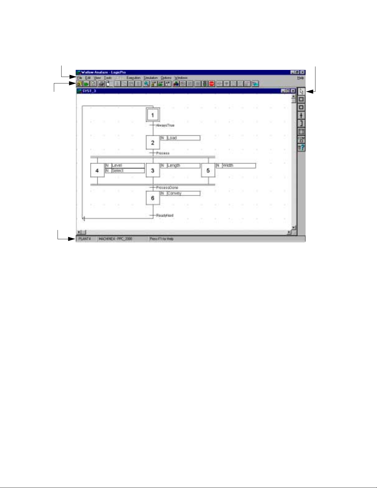
The Workplace is made up of several different Screen
Elements.
workspace and identifies the following elements:
• Menu Bar
• Status Bar
• Standard Toolbar
• Language Toolbars
uses the Microsoft Windows’ Graphical User
LogicPro
LogicPro
screen elements, as well as a reference to some of
Figure 2.1 on page 6
environment allows you to
, you should know how to use
illustrates the
LogicPro
Doc.# 28002-00 Rev 3.00 Watlow Anafaze 5
Page 22
Chapter 2: LogicPro Workplace LogicPro User’s Guide
Menu Bar
Standard
Toolbar
Status
Bar
Language
Toolbar
Menu Bar
Figure 2.1 The LogicPro Workplace
There are two ways to choose an item from a menu:
• With the mouse, click a menu then click the item.
– or –
• Press the
menu’s name, and press the underlined letter in the
item’s name.
There are ten (10) menus available:
• File
• Edit
• View
• Tools
• UDFB
• Execution
• Simulation
• Options
<ALT>
key, press the underlined letter in the
6 Watlow Anafaze Doc.# 28002-00 Rev 3.00
Page 23

LogicPro User’s Guide Chapter 2: LogicPro Workplace
• Windows
• Help
LogicPro enables the appropriate menus. Each of these menus
allows control of a specific part of LogicPro.
File Menu
This menu provides easy access to most tools you will need
for creating, opening and saving files and printing reports.
Additionally, tools for Importing and Exporting variables are
available. See Table 2.1 for a detailed listing of menu items.
Table 2.1 The File Menu
Menu Option Description
Creates a new file type from the
menu:
Project…
New
Open
Close
Delete
Save
Save As…
Resource…
Program…
User Defined Function Block…
Opens a file type from the menu:
Project…
Resource…
Program…
User Defined Function Block…
Closes the chosen type of item:
Project…
Resource…
Program…
User Defined Function Block…
Simulation
Monitoring
Deletes the chosen type of item:
Project…
Resource…
Program…
User Defined Function Block…
Saves the program in the active (top)
window.
Saves the information in the active
window under a different file name.
Doc.# 28002-00 Rev 3.00 Watlow Anafaze 7
Page 24

Chapter 2: LogicPro Workplace LogicPro User’s Guide
Menu Option Description
Creates a backup copy of the chosen
type of item:
Backup
Import Variable
Export Variable
Report Setup…
Print Setup…
Print…
Exit
Project…
Resource…
Program…
Reads data from an ASCII, commadelimited file. Allows you to create
and edit resource and program variables externally to LogicPro.
Writes data to an ASCII, commadelimited file. Allows you to edit
resource and program variables
external to LogicPro.
Allows you to customize your documentation by specifying what information appears in the printout.
Customize user defined print options:
Which printer to print on.
Size and orientation of the paper, and
how to print (single-sided or doublesided if your printer can print doublesided).
Printer resolution, intensity, and
graphics mode.
The kinds of fonts to use while printing.
Things like print quality and memory
tracking for the printer.
Prints selected portion of an open
project or program.
Closes all open projects and shuts
down LogicPro.
Edit Menu
This menu provides useful tools for managing changes for the
data in the active window. See Table 2.2 on page 9 for a
detailed listing of menu items.
8 Watlow Anafaze Doc.# 28002-00 Rev 3.00
Page 25

LogicPro User’s Guide Chapter 2: LogicPro Workplace
Table 2.2 The Edit Menu
Menu Option
Undo
Cut
<Ctrl X>
Copy
<Ctrl C>
Paste
<Ctrl V>
Find…
Replace…
Description
Note: This option is only available while
editing UDFB C/C++ source (*.c) and
header (*.h) files.
Also, note that the Undo buffer is only
one level deep: it only contains the last
keystroke . Selecting Undo twice will perform a ‘double-undo’, or redo.
Restores what you are working on to the
way it was before your very last action.
For example if you overwrite a line of
code, this command will remove your
edits and restore the line as it was
before you began.
Removes the selected objects and
places them in a temporary file. This
material remains in the temporary file
until overwritten by subsequent Cut or
Copy actions, or until you close
LogicPro.
The Cut feature works the same way
when working with UDFBs, except that
the data is stored on the Windows Clipboard, not the LogicPro temporary file.
Creates a duplicate of the selected
object without removing it (see note
below), and places it in a temporary file.
This material remains in the temporary
file until overwritten by subsequent Cut
or Copy actions, or until you close
LogicPro.
The Copy feature works the same way
when working with UDFBs, except that
the data is stored on the Windows Clipboard, not the LogicPro temporary file.
Places the content of the temporary file
into the active window at the insertion
point. If you are pasting in a UBFB, it is
the content of the clipboard that is
placed in the active window.
Pasting does not clear the temporary
file. The last item placed into it stays
there until subsequent Copy or Cut
actions, or until you close LogicPro.
Searches the active window for a specific variable.
Searches the active window for every
instance of a specific value and replaces
it with a new, user-defined value.
Doc.# 28002-00 Rev 3.00 Watlow Anafaze 9
Page 26

Chapter 2: LogicPro Workplace LogicPro User’s Guide
Menu Option
Clear
Del
Variables
Attributes
Description
Deletes the selected area from the
active window. This operation cannot be
undone.
Opens a dialog box and allows you to
manage the different kinds of variables.
Select the variable type from the following list:
Project…
Resource…
Program…
Changes the attributes of an object
within an existing project.
Modifies the different configurations
dependent on your selection from the
following submenu:
Resource…
Driver…
Program…
Action…
User Defined Function Block…
NOTE! Changes to variables within LogicPro (such as
Add, Edit, or Delete) take place immediately and
do not depend on a Program save.
Cut, Copy and Paste functions are available primarily with text and cannot be used with most
graphical program objects. To test if an object can
be cut, copied or pasted, select it then select the
Edit menu item to see if the Cut and Copy selections are available.
You can only paste cut or copied elements or text
into a window of the same type. For example, if
you copy a rung from a ladder diagram you can
only paste it into a ladder diagram. LogicPro disables the paste function if you are in a different
language type window.
10 Watlow Anafaze Doc.# 28002-00 Rev 3.00
Page 27

LogicPro User’s Guide Chapter 2: LogicPro Workplace
View Menu
This menu allows you to customize the appearance of your
workspace. See Table 2.3 for a detailed listing of each menu
item. An enabled selection is easily identified by a checkmark
to the left of a menu item.
Table 2.3 The View Menu
Menu Option Description
Changes the magnification for the
active window from 10% - 200%. This
option allows you to view as little or as
much of the active window as you
Zoom…
Repaint
Grid
Comments
Monitor Program
Monitor On/Off
Configuration
desire.
Zoom settings are only kept while the
window is open. The next time you
open the window the zoom setting
reverts to the default 100% setting.
Redraws the active window and displays the latest changes recorded in
the system.
Superimposes a grid pattern over the
workspace as an aid to placing items.
Allows you to toggle ladder rung comments on and off in the active window.
Allows you to see the real-time status
of the downloaded PLC program.
Allows you to selectively suspend
real-time monitoring messages to a
PLC program on a window by windo w
basis.
Displays a partial IEC 1131-3 configuration descriptor.
Tools Menu
This menu contains the tools associated with your choice of
programming language. Choose your programming language
in the first menu item. The other available options are driven
by this choice. See Table 2.4 on page 12 for a detailed listing
of the languages and their options.
Doc.# 28002-00 Rev 3.00 Watlow Anafaze 11
Page 28

Chapter 2: LogicPro Workplace LogicPro User’s Guide
Table 2.4 The Tools Menu
Menu Option Description
Select the programming language for
the active window from the submenu:
SFC - Grafcet Sequential Function
Chart language. This is the LogicPro
default language for any program window. You may change the defaults
Language
Tools
using the Options menu.
LD - Ladder This option selects the
Ladder Diagram language for the
active window.
FBD - This option selects the Function
Block Diagram language for the active
window.
The selected language determines the
options for the rest of this menu. The
options displayed correspond directly
with the tools available from the different Language Toolbars. For more information, please refer to the appropriate
section concerning the language you
wish information on.
NOTE: Once you select a language
and start to build a program, LogicPro
prevents you from changing the language as long as any element exists in
the window.
UDFB (User Defined Function Block) Menu
This menu gives you control over the various tools available
when you’re creating or editing a UDFB. There are compile
and build options available for both execution and simulation
purposes because each creates its own variant of the UDFB
and saves it in the corresponding library. See Table 2.5 on
page 13 for a detailed list and explanation of the items on the
UDFB menu.
12 Watlow Anafaze Doc.# 28002-00 Rev 3.00
Page 29

LogicPro User’s Guide Chapter 2: LogicPro Workplace
Table 2.5 The UDFB Menu
Menu Option Description
Compiles and error checks a
Compile for
Execution
Build Execution
Lib…
Compile for
Simulation
Build Simulation
Lib…
UDFB in the active window for
downloading, using the compiler
selected for the particular
resource.
Performs the same function as
Compile for Execution (above),
but also adds the .OBJ file to the
UDFB library for this resource
type. You must add a UDFB to the
library before you can use it in a
program.
Compiles and error checks the
UDFB in the active window for
simulation using the Borland
C++ compiler.
Performs the same function as
Compile for Simulation (above),
but also adds the .OBJ file to the
UDFB library for this resource
type. You must add a UDFB to the
library before you can use it in a
program.
Execution Menu
Simulation Menu
This menu contains many useful tools that you will need to
compile, link, download, stop, and start a project. See
Table 2.6 for a detailed list and explanation of the items on the
Execution menu.
Table 2.6 The Execution Menu
Menu Option Description
Build All and
Run
Download and
Run
Start Executable
Terminate Stops the currently running program.
This menu gives you control over all aspects of running a
simulation. Refer to Table 2.7 on page 14.
Compiles, downloads and starts the
program.
Downloads and starts a previously
compiled program.
Starts a previously downloaded program.
Doc.# 28002-00 Rev 3.00 Watlow Anafaze 13
Page 30

Chapter 2: LogicPro Workplace LogicPro User’s Guide
Table 2.7 The Simulation Menu
Menu Option Description
Build All and
Run
Simulation
Setup…
Simulation Reset
Scan
Increment Timer
Change
Variable…
Compiles and links a program for
simulation and runs the simulation.
Opens the Simulation Setup dialog
box, allowing you to set the number
of milliseconds that elapse per scan,
as well as establishing the number of
logic scans per simulation scan.
Resets all variables and the program
state back to their original values.
Executes a single scan of the simulation based on the simulation setup
criteria. This feature is only available
if you are not in the continuous scan
mode.
Advances the timer by the number of
“ticks” defined in the Simulation
Setup dialog box.
Opens the Change Variables dialog
box, allowing you to change the v alue
of any variable in the program for simulation purposes.
Options Menu
This menu allows you to customize the LogicPro
development environment. To activate an option, select the
menu item. A check mark appearing to the left of an item
indicates the option is active. If there is no check mark, the
option is inactive. See Table 2.8.
Table 2.8 The Options Menu
Menu Option Description
Resource
Compiler
Selection
Allows you to establish a path to the
directory containing the compiler,
linker, includes, etc.
14 Watlow Anafaze Doc.# 28002-00 Rev 3.00
Page 31

LogicPro User’s Guide Chapter 2: LogicPro Workplace
Menu Option Description
Customize the application workspace
using the following submenu:
Display Grid by Default - Toggles the
default setting for displa y grid between
either on or off. The grid can also be
turned on or off independently on a
window-by-window basis on the View
menu.
Display Comments by Default - Tog-
Program Window
Variable
AutoSave
FastLink Config
Fording Options
gles the default setting for display
comments between either on or off.
Comments can also be turned on or
off independently on a window-by-window basis on the View menu.
Default Language - Selects the
default language for ne w prog ram windows. The options are:
SFC (default language)
Ladder
FBD
Customize how variables are handled.
Confirm Deletion - If selected, Log-
icPro prompts you to confirm your
intention to make a deletion.
Confirm Edit Change - If selected,
LogicPro prompts you to confirm your
intention to save a change.
Auto SFC Operator - If selected, the
operator dialog box opens automatically if you attempt to build a transition
expression.
Allows you to toggle the AutoSave
feature (on and off) and set the save
interval (from 5 to 120 minutes).
Establishes a connection between
FastLink, the LogicPro data API and a
single LogicPro project. This allows
you to browse for the .FLK file-path
establishing Access Time, Poll Rate
and Message Time Out.
When monitoring a program, items on
this menu allow you to enable, disable, or clear fording of v ariables. See
Forcing I/O on page 240.
Doc.# 28002-00 Rev 3.00 Watlow Anafaze 15
Page 32

Chapter 2: LogicPro Workplace LogicPro User’s Guide
Windows Menu
This menu offers additional tools for customizing your
LogicPro workspace. Specifically, it provides a list of open
windows and allows you to change the dimensions and
arrangement of those windows. Refer to Table 2.9.
Table 2.9 The Windows Menu
Menu Option Description
Arranges all of the open windows in
Cascade
Tile
Arrange Icons
Close All
(Open Window)
an overlapping fashion so that the
title bars of each are visible, with the
currently active window on top.
Arranges all of the open windows
next to each other.
NOTE: Tile displays all of the open
windows equally and side-by-side
within the program window . The more
windows you have open when you
tile, the less of each you will see.
Organizes the icons that represent
the minimized windows in your program. This option arranges the icons
along the lower left-hand edge of the
workspace.
Closes all the windows associated
with the:
Program
Simulation
Monitoring
UDFB
All Windows
Currently open windows, if any, are
listed. To change the active window
to any of the currently open windows,
simply point to the desired window
on the list and click. A check-mark
appears to the left of the active window.
16 Watlow Anafaze Doc.# 28002-00 Rev 3.00
Page 33

LogicPro User’s Guide Chapter 2: LogicPro Workplace
Help Menu
The Help menu gives you access to the online documentation
system. This allows you to obtain information about software
features and functions while in the middle of a development
task.
There are three levels of information in the online help
system, as described in Table 2.10.
Table 2.10 Levels of Help
Type of Help Access
Complete online help. Use the Help menu.
Information about the
active dialog box or
pull-down menu.
Information about the
selected menu item.
Help Menu Commands
Click a Help button or press <F1>.
Press <F1>.
Table 2.11 briefly describes each Help menu command.
Table 2.11 Help Menu Options
Command Description
Accesses the LogicPro Help Contents. Simply click on any of the
Index…
Search for Help
On…
How to Use Help…
About LogicPro
underlined topics to navigate
through the Help system. This will
display either the appropriate help
topic or an index of related topics.
Lets you define a keyword to
search on. The Help system then
lists the keyword's related topics
and lets you select one.
Explains how to use the online help
system.
Displays copyright and version
information along with other product information and limits (Demo,
Standard, Unlimited.)
Doc.# 28002-00 Rev 3.00 Watlow Anafaze 17
Page 34

Chapter 2: LogicPro Workplace LogicPro User’s Guide
Status Bar
The Status bar displays project, resource, and resource type
names, from left to right at the bottom of the screen, and is
available to the developer within the development
environment. The Status bar also provides information about
the currently highlighted menu item.
Toolbars
There are two different types of toolbars:
• Standard toolbar
• Language toolbars
Each contains tools designed to make creating and managing
LogicPro projects a fast, easy and intuitive process.
Standard Toolbar
The Standard toolbar appears across the top of the screen
under the menu bar. It provides quick access to common
operations, such as deleting an object, adjusting the screens
zoom setting, saving, monitoring, compiling, starting and
stopping. ToolTips display on-screen descriptions of all
toolbar buttons simply by pausing the pointer on them.
Figure 2.2 Two Views of the LogicPro
Standard toolbar, showing
various active buttons
Table 2.12 Toolbar Definitions
Button Description
Open Project
Open Resource
Open Program
18 Watlow Anafaze Doc.# 28002-00 Rev 3.00
Page 35

LogicPro User’s Guide Chapter 2: LogicPro Workplace
Button Description
Print Documentation
Save
Edit Cut
Edit Copy
Edit Paste
Edit Delete
Zoom Ratio
Edit Project Variable(s)
Edit Resource Variable(s)
Edit Program Variable(s)
Build All and Run Execution
Download and Run
Open Program for Monitoring
Disabled Status Update
Run Execution
Terminate Execution
Simulation Setup
Simulation Reset
Scan Simulating Logic
Increment Simulation Timer Tick
Change Simulation Variable(s)
Repaint Window
Doc.# 28002-00 Rev 3.00 Watlow Anafaze 19
Page 36

Chapter 2: LogicPro Workplace LogicPro User’s Guide
Language Toolbars
The Language toolbars appear down the right side of the
screen. Tools represent each of the language elements used in
building a program in a particular language. This Toolbar
automatically changes to reflect the current programming
language. ToolTips are available on all the buttons so that you
can easily identify their functions.
Each of the tools available on these toolbars is full explained
in the section covering the particular language.
Toolbar Explanation Page
Sequential Function Charts 72
Ladder 82
Function Block Diagram 106
NOTE! The Language toolbar is only visible when a pro-
gram editor window is open and on top.
Table 2.13 The SFC Toolbar
Tool Description
Selector
Origin Step
Step
Simultaneous Transition
(Directed Link)
Loop Back (Connection)
Action
Comments
Cross Reference
20 Watlow Anafaze Doc.# 28002-00 Rev 3.00
Page 37

LogicPro User’s Guide Chapter 2: LogicPro Workplace
Table 2.14 The Ladder Toolbar
Tool Description
Selector
Normally Open Contact
Normally Closed Contact
Off to On Transitional Contact (Positive)
On to Off Transitional Contact (Negative)
Normal Coil
Latched Coil (Set)
Unlatched Coil (Reset)
Function Block
Comments
Cross Reference
Table 2.15 The FBD Toolbar
Tool Description
Selector
Straight Connector
Inverted Connector
Variable
Function Block
Cross Reference
Doc.# 28002-00 Rev 3.00 Watlow Anafaze 21
Page 38

Chapter 2: LogicPro Workplace LogicPro User’s Guide
Using Standard Windows Features
LogicPro provides standard Windows features. If you are
already familiar with Windows, the Select, Cut, Copy and
Paste tasks are familiar.
You can access the Cut, Copy or Paste commands from
Edit on the Menu Bar, or from the buttons on the Standard
toolbar. You can also access these features using the short cut
keys (<Ctrl + X>, <Ctrl + C>, and <Ctrl + V> respectively).
SFC Actions
Programming
Language
SFC Actions
Ladder Diagram Ladder Rungs
UDFB Text
Cut and copy SFC actions in the following manner:
1. Click the action with the Selector tool. This creates
handles around the action.
2. Use the short cut keys or menu options to either
Copy the action onto the clipboard.
3. Paste the action into other SFC diagrams using either
the Edit menu or short cut keys.
If you paste the action on to the same level of SFC, you must
change the action name. The editor will prompt you for this
change when required.
Pasted items appear at the bottom of the list. If you need the
pasted section to appear higher-up in your diagram you must
cut everything above it and paste it below.
Items that can be Cut, Copied
or Pasted
Cut or
Ladder Rungs
Edit Ladder rungs in the following manner:
1. Click the rung number to the left of the ladder rung with
the Selector tool. Multiple rungs can be simultaneously
selected, or lassoed.
2. Use the short cut keys or menu options to either Cut or
Copy the selection onto the clipboard.
3. Paste the contents of the clipboard into any ladder diagram using either the Edit menu or short cut keys.
22 Watlow Anafaze Doc.# 28002-00 Rev 3.00
Page 39

LogicPro User’s Guide Chapter 2: LogicPro Workplace
Standard Text
To Cut, Copy and Paste text from the UDFB editor:
1. Select the text you wish to copy by holding down the left
mouse button while dragging it across the desired text.
2. Use the short cut keys or menu options to either Cut or
Copy the selection onto the clipboard.
Paste the contents of the clipboard into any part of the UDFB
editor using either the Edit menu or short cut keys.
Doc.# 28002-00 Rev 3.00 Watlow Anafaze 23
Page 40

Chapter 2: LogicPro Workplace LogicPro User’s Guide
24 Watlow Anafaze Doc.# 28002-00 Rev 3.00
Page 41

3
Projects
Before you begin it is important that you understand the structure and building blocks of a LogicPro Project. The Project
itself resides at the highest level of this hierarchy. The next
level is called the Resource level. A Resource is the controller
hardware that will run a logic program. A project may consist
of many resources, or as few as one. Each resource contains
one or more Programs. At the lowest level is the Action.
Actions reside within the programs. The following diagram
illustrates these building blocks and their relationship to each
other.
Project P
Resource A
Program R
Action a
Action b
Action c
Program m
Action 3
Figure 3.1 Projects Hierarchy
Each LogicPro project resides within a separate directory or
folder. The software creates a new directory for each new
project. As the developer, you can organize projects by
selecting where LogicPro creates the directory.
Doc.# 28002-00 Rev 3.00 Watlow Anafaze 25
Resource 1
Program V
Action e
Action r
Program m
Action 3
Program 4
Action 0
Page 42

Chapter 3: Projects LogicPro User’s Guide
The directory’s name corresponds to the project’s name and
the contains all of the resource subdirectories. These
subdirectories, in turn, contain all the resource and program
files.
In LogicPro, the project is a receptacle for all related
resources and programs. The project contains all the
programmable controller elements necessary to describe and
implement an automated task.
Projects can contain any number of resources and programs.
This enables you to set-up Projects with numerous controllers
and steps, or smaller projects with only one or two resources.
Creating a Project
Creating a Project is the first task when using LogicPro. You
must create a Project before you can:
• Configure a controller resource.
• Design a program for a device.
• Define individual action steps.
To create a new project:
1. Select the File menu.
2. Select New.
3. Select Project. The New Project dialog box appears,
as shown in Figure 3.2.
Figure 3.2 New Project Dialog Box
26 Watlow Anafaze Doc.# 28002-00 Rev 3.00
Page 43

LogicPro User’s Guide Chapter 3: Projects
4. Select the directory in which you want to store your new
project.
5. Enter the name for the New Project. The Project name
must conform to standard DOS naming conventions and
have no more than eight characters.
6. Click [OK].
LogicPro creates a new directory on your drive. This directory
contains all the files related to this Project. LogicPro
automatically prompts you to create a New Resource. See
“Editing a Resource” on page 36 for how to create a New
Resource. You cannot use resources that have been created
under other Projects with your New Project.
Opening a Project
To open an existing Project:
1. Select the File menu.
2. Select Open.
3. Select Project. The Open Project dialog box appears,
as shown in Figure 3.3.
Figure 3.3 Open Project Dialog Box
Doc.# 28002-00 Rev 3.00 Watlow Anafaze 27
Page 44

Chapter 3: Projects LogicPro User’s Guide
4. Click on a Project in the box.
5. Click [OK]. LogicPro automatically prompts you to
open a Resource and then a Program if any exist or to
create them. See Chapter 5, Programs.
6. If you cannot find the Project you are looking for,
a) Select Build List from the dialog box. The
Rebuild Project List dialog box appears, as
shown in Figure 3.4.
b) Enter a drive in the Start Drive and End Drive
fields. LogicPro searches the drive(s) entered and
produces a list of all available projects.
Figure 3.4 Rebuild Project List Dialog Box
Copying Projects
Projects, Resources and Programs are stored in files and
directories that can be copied to a floppy or another drive
location. However, the structure between these must be
maintained for LogicPro to read files correctly. Each Project
has its own directory with the same name as the project. Each
Resource also has its own directory with the same name as the
Resource; it is located in the associated Project directory.
Programs are composed of several files which are located in
the Resource directory.
28 Watlow Anafaze Doc.# 28002-00 Rev 3.00
Page 45

LogicPro User’s Guide Chapter 3: Projects
To copy a Project:
1. If a Project is being used by LogicPro, close it.
a) Select File.
b) Select Close.
c) Select Project.
2. Copy the Project directory using any file utility such as
Windows Explorer. Copy the entire directory including
all files and subdirectories. Do not rename any directory
or file name; LogicPro will not recognize a Project in a
folder if the name has been changed.
3. Open the Project.
a) Select File.
b) Select Open.
c) Select Project. The Open Project dialog box ap-
d) The Project will not be listed. Select Build List
e) Enter a drive in the Start Drive and End Drive
f) Click on the copied Project.
g) Click [OK].
Backing Up a Project
You can back up or copy a project to any location that is
accessible to the computer. Backing up is the equivalent to
Save As for projects. To backup a project:
NOTE! A project must be closed before you can back it
up!
pears, as shown in Figure 3.3 on page 27.
from the dialog box. The Rebuild Project List
dialog box appears, as shown in Figure 3.4 on page
28.
fields. LogicPro searches the drive(s) entered and
produces a list of all available Projects.
Doc.# 28002-00 Rev 3.00 Watlow Anafaze 29
Page 46

Chapter 3: Projects LogicPro User’s Guide
1. Select the File menu.
2. Select Backup.
3. Select Project. The Copy Project dialog box appears,
as shown in Figure 3.5.
4. Select the Project to be backed up from the list of
Existing Project(s). Enter the new name for the
backup copy of the project.
5. Select the drive and directory in which LogicPro should
place the copy.
NOTE! If you are backing up the project to protect it from
mechanical failure, then it should be stored on a
different disk drive or storage
media.
6. Click [OK].
Figure 3.5 Copy Project Dialog Box
30 Watlow Anafaze Doc.# 28002-00 Rev 3.00
Page 47

LogicPro User’s Guide Chapter 3: Projects
Closing a Project
To close a Project:
1. Select the File menu.
2. Select Close.
3. Select Project.
If any of the Programs within the Project you are closing have
changed, LogicPro prompts you to save your changes before
it closes the Project.
Deleting a Project
NOTE! A Project must be closed before it will appear on
the list of Projects that may be deleted.
To delete a Project:
1. Select the File menu.
2. Select Delete.
3. Select Project. The Delete Project dialog box
appears, as shown in Figure 3.6 on page 32.
4. Select the Project or Projects you want to delete from the
list. By default, no projects are selected when the dialog
box appears. Click on a Project once to select it for
deletion. Click on it a second time to deselect it. Double
clicking on an unselected Project is equivalent to
selecting it and clicking the [OK] button.
5. Click [OK]. A message dialog box appears to confirm
deletion of the Project and all its Resources and
Programs.
NOTE! If you click [OK], you remove the Project names
from the list and delete all associated Resource
and Program files. There is no way to recover this
information. Be certain you want to delete these
files before you click [OK].
6. Click [OK] to confirm the deletion
– or –
[Cancel] to abort the deletion.
Doc.# 28002-00 Rev 3.00 Watlow Anafaze 31
Page 48

Chapter 3: Projects LogicPro User’s Guide
Figure 3.6 Delete Project Dialog Box
32 Watlow Anafaze Doc.# 28002-00 Rev 3.00
Page 49

Resources are the individual controllers that execute the logic
you created in a LogicPro Program.
Creating a Resource
To create a Resource:
1. Select the File menu.
2. Select New.
3. Select Resource. The New Resource dialog box
appears, as shown in Figure 4.1.
4
Resources
Figure 4.1 New Resource Dialog Box
4. Select PPC_2000 or CPC400 from the Target
Environment list.
Doc.# 28002-00 Rev 3.00 Watlow Anafaze 33
Page 50

Chapter 4: Resources LogicPro User’s Guide
5. Enter a Name for the Resource you want to define.
LogicPro saves this Resource as a database in the Project
subdirectory.
6. Click [OK] to define the Resource. The Attributes
dialog box appears.
– or –
Click [Cancel] to exit the dialog box.
Figure 4.2 PPC-2000 Attributes Dialog Box
PPC-2000 Attributes
The following LogicPro default communications settings will
match the PPC-2000’s port 1 when the rotary CONFIG switch
is set to position A.
• Baud: 19200
• Parity: Even
• Device Address: 1
34 Watlow Anafaze Doc.# 28002-00 Rev 3.00
Page 51

LogicPro User’s Guide Chapter 4: Resources
To configure communications with the PPC-2000:
1. Select the correct Communication Port for your PC.
2. Select a Parity of Even, Odd or None.
3. In the Device Address field, enter the controller
address for the PPC-2000.
4. In the ROM Size field, enter 128kB. (Controllers with
2.03 and earlier firmware support up to 40 kB.
5. Select a Baud Rate. The PPC-2000 supports 9600 and
19200.
6. In the Time out field, enter 2000 milliseconds.
7. Click [OK]
-or-
Click [Cancel] to exit this screen.
CPC400 Attributes
The CPC400 has the following default communication
settings:
• Baud Rate: 19200
• Controller Address: 1
To configure communications with the CPC400:
1. Select the correct Communication Port for your PC.
2. Select a Parity of None.
3. In the Device Address field enter the controller
address you set in the CPC400.
4. In the ROM Size field, enter 64 kB.
5. Select a Baud Rate. The CPC400 supports 2400, 9600
and 19200.
6. In the Time out field enter 2000 milliseconds.
7. Click [OK]
-or-
Click [Cancel] to exit this screen.
Doc.# 28002-00 Rev 3.00 Watlow Anafaze 35
Page 52

Chapter 4: Resources LogicPro User’s Guide
Editing a Resource
To edit the open Resource:
1. Select the Edit menu.
2. Select Attributes.
3. Select Resource. The Edit Resource dialog box
appears. See Figure 4.3 with the current Resource type
highlighted.
4. Click [OK] to open the Attributes dialog box
– or –
Click [Cancel] to exit the dialog box.
5. Make the desired changes to the settings.
NOTE! This is the same dialog box used when creating a
New Resource. See “Creating a Resource” on
page 33 for an explanation of the various Resource parameters.
Figure 4.3 Edit Resource Dialog Box
Copying Resources
Resources must be copied within the context of their Projects.
To copy a Resource:
1. Copy or back up the Project containing the target
Resource and then open it. See “Copying Projects” on
page 28 and See “Backing Up a Project” on page 29
36 Watlow Anafaze Doc.# 28002-00 Rev 3.00
Page 53

LogicPro User’s Guide Chapter 4: Resources
2. Since the project may contain many different Resources,
delete any unnecessary Resources.
a) Select File.
b) Select Delete.
c) Select Resources. The Delete Resources di-
alog box appears.
d) Select the Resources to delete.
e) Click [OK].
The temp directories can be deleted to minimize the size of the
project. Using any file utility such as Windows Explorer
delete the temp directories (1bk~ through 5bk~) located
within the Project directory.
Resource Backup
Backup, the precautionary copying of your Resource files to
an alternative location, is an important step in protecting your
work from equipment failure. You must meet two conditions
in order to backup a Resource.
• The Resource must exist within the open Project.
• The Resource must be closed.
You cannot move or copy a Resource outside its original
Project.
To backup a Resource:
1. Select the File menu.
2. Select Backup.
3. Select Resource. The Copy Resource dialog box
appears, as shown in Figure 4.4 on page 38.
4. Select the Resource you want to back up by clicking on
it in the Existing Resources list.
5. Enter a new name in the New Resource Name field.
6. Click [OK].
NOTE! This is very useful for duplicating controller ele-
ments that repeat.
Doc.# 28002-00 Rev 3.00 Watlow Anafaze 37
Page 54

Chapter 4: Resources LogicPro User’s Guide
Figure 4.4 Copy Resource Dialog Box
Deleting a Resource
This option irreversibly removes an existing Resource from
the current Project.
1. Select the File menu.
2. Select Delete.
3. Select Resource. The Delete Resource dialog box
appears, as shown in Figure 4.5 on page 39.
4. Select the Resource or Resources you want to delete
from the list. You can delete multiple Resources
simultaneously. By default no Resources are selected
when the dialog box appears. Click on a Resource once
to select it. Click a second time to deselect it. Double
clicking an unselected Resource is equivalent to
selecting it and clicking [OK].
5. Click [OK]. A message dialog box appears to confirm
deletion of the Resource and all its Programs.
NOTE! By clicking [OK], you remove the Resource name
from the list and delete all associated Program
files. There is no way to recover this information,
so be absolutely certain you want to delete these
files before you click [OK].
6. Click [OK] to accept the deletion
– or –
Click [Cancel] to abort the deletion.
38 Watlow Anafaze Doc.# 28002-00 Rev 3.00
Page 55

LogicPro User’s Guide Chapter 4: Resources
Figure 4.5 Delete Resource Dialog Box
Opening a Resource
This option makes the Resource available to you.
1. Select the File menu.
2. Select Open.
3. Select Resource. The Open Resource dialog box
appears, as shown in Figure 4.6.
4. Select the Resource you want to open from the list of
Resources.
5. Click [OK]. The Resource opens displaying its name on
the status line. You are then prompted to open a Program.
See “Opening a Program” on page 42.
Figure 4.6 Open Resource Dialog Box
Doc.# 28002-00 Rev 3.00 Watlow Anafaze 39
Page 56

Chapter 4: Resources LogicPro User’s Guide
40 Watlow Anafaze Doc.# 28002-00 Rev 3.00
Page 57

5
Programs
Programs form the base unit of the LogicPro development
environment. Programs are defined in IEC 1131-3 as logical
assemblies of all the programming language elements and
constructs necessary for the intended signal processing
needed to control a machine or process by a programmable
controller system.
One or more Programs can be contained within a Resource.
Within each Program, there may be any number (including
zero) of steps, actions, relay elements, or function blocks.
While you can write multiple Programs for each controller,
only one Program can actually run on the Resource at any
time.
Creating a New Program
1. Select the File menu.
2. Select New.
3. Select Program. The New Program dialog box ap-
pears, as shown in Figure 5.1 on page 42.
Doc.# 28002-00 Rev 3.00 Watlow Anafaze 41
Page 58

Chapter 5: Programs LogicPro User’s Guide
Figure 5.1 New Program Dialog Box
4. Enter the name for the new Program. Since the Program
name is used as the name of DOS data files, the name
must conform to DOS standards for file names. The
name cannot be the same as the Resource name. See
Appendix A for details on naming conventions.
5. Click [OK].
Opening a Program
To open an existing Program:
1. Select the File menu.
2. Select Open.
3. Select Program. The Open Program dialog box
appears, as shown in Figure 5.2 on page 43.
4. Select the Program you want to open from the list.
5. Click [OK].
42 Watlow Anafaze Doc.# 28002-00 Rev 3.00
Page 59

LogicPro User’s Guide Chapter 5: Programs
Figure 5.2 Open Program Dialog Box
Saving a Program
When you save a Program, LogicPro creates a backup file that
contains the previously saved version of the Program. The
Program appears as a .THR file and the backup file appears as
a .BAK file in the Resource directory.
To save the currently active Program window:
1. Select the File menu.
2. Select Save.
Closing a Program
To close a Program:
1. Select the editor window with the Program you wish to
2. Select the File menu.
3. Select Close.
4. Select Program. A message dialog box appears as
close from the Windows menu if it is not already select-
ed (on top).
shown in Figure 5.3 on page 44 if any changes have been
made and not saved.
Doc.# 28002-00 Rev 3.00 Watlow Anafaze 43
Page 60

Chapter 5: Programs LogicPro User’s Guide
5. Click [Yes] to save the Program and create a backup file
of the old Program.
– or –
Click [No] to close the Program without saving.
– or –
Click [Cancel] to leave the Program open.
NOTE! Additions and deletions of variable definitions are
saved when made and do not depend on saving
the Program.
Figure 5.3 Verify Dialog Box
Copying Programs
Programs must be copied within the context of their Projects
and resources. To copy a Program:
1. Copy or back up the Project containing the target Pro-
2. Since the Project may contain many Resources, delete all
gram and then open it. “Copying Projects” on page 28.
and “Backing Up a Project” on page 29.
Resources that do not contain the target Program.
a) Select File.
b) Select Delete.
c) Select Resources. The Delete Resources
dialog box appears.
d) Select the Resources to delete.
e) Click [OK].
44 Watlow Anafaze Doc.# 28002-00 Rev 3.00
Page 61

LogicPro User’s Guide Chapter 5: Programs
3. Since the Resource may contain many different
Programs, delete any unnecessary Programs.
a) Select File.
b) Select Delete.
c) Select Programs. The Delete Program dialog
box appears.
d) Select the Programs to delete.
e) Click [OK].
The temp directories can be deleted to minimize the size of the
Project. Using any file utility such as Windows Explorer
delete the temp directories (1bk~ through 5bk~) located
within the Project directory.
Saving a Program with a New Name (Save As)
The Save As feature allows you to save an open Program
under a new name. To use this feature:
1. Select the File menu.
2. Select Save As.
3. Enter the new name you wish the Program to be saved as.
A list of the existing Program names display below this
field. LogicPro will not allow you to overwrite an existing Program.
4. Click [OK] to finish the save.
– or –
Click [Cancel] to go back to the Program window.
Backing Up a Program
You can backup or copy a Program if:
• The backed-up Program is located within the same
Resource.
• The Program is closed.
You cannot move or copy a Program outside the original
Resource.
Doc.# 28002-00 Rev 3.00 Watlow Anafaze 45
Page 62

Chapter 5: Programs LogicPro User’s Guide
To backup a Program:
1. Select the File menu.
2. Select Backup.
3. Select Program. The Copy Program dialog box
appears, as shown in Figure 5.4.
4. Select the Program you want to backup by clicking on it
in the Existing Program(s) list.
5. Enter the new Program name in the New Program
Name field. A list of the existing Program names is dis-
played below this field to help insure that you do not use
a name that is already assigned.
6. Click [OK] to finish the save
– or –
Click [Cancel] to abort the backup.
If a Program already exists in the Resource with the name you
entered, you are prompted to confirm overwriting the existing
Program.
7. Click [OK] to overwrite the existing Program
– or –
Click [No] to go back to the Copy Program dialog box
and enter a unique name.
Figure 5.4 Copy Program Dialog Box
46 Watlow Anafaze Doc.# 28002-00 Rev 3.00
Page 63

LogicPro User’s Guide Chapter 5: Programs
Deleting a Program
To delete an existing Program:
1. Select the File menu.
2. Select Delete.
3. Select Program. The Delete Program dialog box ap-
pears, as shown in Figure 5.5.
4. Select the Program you want to delete.
Multiple Programs can be selected by clicking on one
Program name after another. To deselect a Program click on
its name a second time.
5. Click [OK]. A message dialog box appears to confirm
that you want to delete the Program and all its associated
variables.
NOTE ! If you click [OK], you remove the Program from
the list and delete all associated files. There is no
way to recover this information, so be certain you
want to delete these files before you click [OK].
6. Click [OK] to delete the Program
-or-
[Cancel] to abort the deletion.
Figure 5.5 Delete Program Dialog Box
Doc.# 28002-00 Rev 3.00 Watlow Anafaze 47
Page 64

Chapter 5: Programs LogicPro User’s Guide
48 Watlow Anafaze Doc.# 28002-00 Rev 3.00
Page 65

A LogicPro Variable is the name tag given to a piece of data
used by various execution elements of the Program. Variables
are both physical I/O and internally represented data.
LogicPro uses several types of Variables, including:
• Project Variables
• Resource Variables
• Program Variables
Naming Conventions
When naming Variables try to be as descriptive as possible
especially if there are more than a few Variables in the
Program. For example, Go_Light_On will prove more useful
a name than Variable_1.
6
Variables
Variables may be up to 28 characters long.
lnitial Value—When a logic program is first run all of
the variables are set equal to the initial values specified
when the variables are declared or created. If an initial
value is not explicitly entered in the Add Variable
dialog box, the variable is set equal to zero. Unless a
variable is set as retentive, it is set equal to its intitial
value each time the logic program is run.
Doc.# 28002-00 Rev 3.00 Watlow Anafaze 49
Page 66

Chapter 6: Variables LogicPro User’s Guide
Retentive Variables
A Retentive Variable is a Variable that:
• Remembers its last state if power is interrupted.
• Returns that value after power has been restored.
LogicPro forgets all of the Variable values when a power
down of a Resource occurs unless they are tagged as
Retentive.
System Variables
System Variables give you access to internal system status
and allow you to view items such as I/O Driver and Resource
status. LogicPro generates these Variables automatically. You
can access System Variables through the Variable List
dialog box in the same manner as Project, Resource, and
Program Variables.
Whenever an driver is referenced in your Program, LogicPro
creates two Variables, Flag and Stat, for each driver.
• Flag Variable — is Boolean in nature and goes high if
an error is detected.
• Stat Variable — is an integer and contains the river
status bits or error code.
LogicPro also creates system variables whenever function
blocks are added to a program. These variables can be used
elsewhere in the program. The system variables are named by
concatenating the user set name of the function block, and the
function block’s I/O symbols. For example, MYTIMER.Q is
a system variable that holds a value of 0 when the output of
function block named MYTIMER is off and a value of 1 when
the output of that function block is on.
To view the existing system variables or assign one to a
program element:
1. Double-click a program element.
2. For Variable Type, select System
3. For Data Type, select All
NOTE! You can view System Variables, only after having
defined a Variable associated with a particular
driver, and you cannot add, delete, or edit them.
50 Watlow Anafaze Doc.# 28002-00 Rev 3.00
Page 67

LogicPro User’s Guide Chapter 6: Variables
Project Variables
Project Variables are available to all elements in a Project.
Project Variables are always internal, they cannot be a
reference to physical I/O or database registers. To add, edit,
and delete Project Variables:
1. Select the Edit menu.
2. Select Variables.
3. Select Project.
This will open the Project Variables dialog box, see Figure
6.1 on page 51.
4. To add a Variable, click [Add]. See “Adding a Re-
source/Program Variable” on page 56.
5. To clone a Variable, select it and click [Clone]. See
“Cloning a Project Variable” on page 55.
6. To edit a Variable, select it and click [Edit]. See “Edit-
ing a Project Variable” on page 53.
7. To delete a Variable, select it and click [Delete]. See
“Deleting a Project Variable” on page 54.
8. Click [OK] to accept the changes
– or –
Click [Cancel] to cancel all the changes.
Figure 6.1 Project Variables Dialog Box
Doc.# 28002-00 Rev 3.00 Watlow Anafaze 51
Page 68

Chapter 6: Variables LogicPro User’s Guide
Adding a Project Variable
To add a Project Variable:
1. Click [Add] in the Project Variable dialog box. This
dialog box to opens, as shown in Figure 6.2.
Figure 6.2 Add Project Variable
2. Enter the Variable name. This name must follow the
Variable naming conventions discussed in “Naming
Conventions” on page 49.
3. If you want to create several Variables with similar
names, enter the root name in the Name field and enter
a starting number and ending number in the Increment
field. By this method, multiple Variables are created,
each named with the root name and each appended with
a number.
4. Select the Variable type from the list of types, either:
• BOOL (Boolean)
• INT (Integer)
• LONG (Long integer)
• REAL (Floating Point)
5. Enter the Initial Variable Value. If this field is left
blank, zero is the default value. The Variable holds the
value of zero until the Program changes that value. Initial
value can be used for constant values of function blocks
or constant true/false Variables.
52 Watlow Anafaze Doc.# 28002-00 Rev 3.00
Page 69

LogicPro User’s Guide Chapter 6: Variables
Boolean Variables — are 1 bit in length and can have a
value of 1 or 0, corresponding to true and false respectively.
Integer Variables — are 16-bit numeric Variables ranging in value from –32,768 to 32,767 including zero.
Long Integer Variables — are 32-bit (double-word) numeric variables ranging in value from -2,147,483,648 to
2,147,483,647.
Real Variables — are numeric variables with floating
point decimals ranging in value from -3.4 x 10
38
.
10
38
to 3.4 x
6. Enter any comments you wish to make about the Vari-
able in the Comment field.
7. Click [OK] when all the parameters for this Variable are
defined.
– or –
Click [OK/Continue] to add the Variable and keep the
Add Project Variable dialog box open and add anoth-
er Variable.
The Variable with the parameters you selected now appears in
the dialog box list. The next time you add a Variable, the Add
Variable dialog box remembers the previously entered type
and size fields. This makes it easier and faster to add many
similar Variables to a Project.
Editing a Project Variable
To edit a Project Variable:
1. Highlight the Variable you want to edit in the list in the
Project Variable dialog box.
2. Click [Edit]. The Edit Project Variable dialog box ap-
pears, as shown in Figure 6.3 on page 54.
3. Edit the Variable name, type or initial value.
4. Click [OK] when all the parameters for this Variable are
defined.
With the Edit Project Variable dialog box open you can:
• Open a new Edit Project Variable dialog box and add
a New Variable by clicking the [Add] button.
• Duplicate the existing Variable’s settings in a new Edit
Project Variable dialog box by clicking the [Clone]
button.
• Delete the Variable you are editing by clicking the
[Delete] button.
Doc.# 28002-00 Rev 3.00 Watlow Anafaze 53
Page 70

Chapter 6: Variables LogicPro User’s Guide
Figure 6.3 Edit Project Variable Dialog Box
Deleting a Project Variable
To delete a single Project Variable:
1. Select the Variable you want to delete in the Project
Variables dialog box.
2. Click the [Delete] button. The Verify dialog box ap-
pears.
NOTE! You are prompted to confirm deletion only if the
Options/Variable/Confirm/Deletion
choice is selected.
3. Click [Yes] to delete the Variable
– or –
Click [No] to cancel the deletion.
To delete multiple Variables simultaneously:
1. Select the first Variable you want to delete in the
Project Variables dialog box.
2. To select another non-sequential Variable:
a) Press and hold <CTRL>.
b) Click the additional Variables you want to delete.
Only the first selection and the additional Variables
are highlighted.
54 Watlow Anafaze Doc.# 28002-00 Rev 3.00
Page 71

LogicPro User’s Guide Chapter 6: Variables
To select a sequence of Variables:
c) Press and hold <SHIFT>.
d) Click on the last in the sequence of Variables you
want to delete. This action highlights the first selection, the last selection, and all of the Variables in
between the two.
3. Click [Delete]. The Verify dialog box appears.
NOTE! You are prompted to confirm deletion only if the
Options/Variable/Confirm/Deletion
choice is selected.
4. Click [Yes] to delete the Variables.
–or –
Click [No] to cancel the deletion.
NOTE ! If you make a mistake, you can use the [Cancel]
button to restore all settings to the state in which
they existed when you first opened the Project
Variables dialog box.
Cloning a Project Variable
Cloning a Variable creates an exact duplicate of that Variable
and highlights the symbolic name of the copied Variable. This
makes the creation of similar Variables easier.
To clone a Project Variable:
1. Select the Variable you want to clone from the list in the
Project Variables dialog box.
2. Click [Clone]. The Add Project Variable dialog box
is opened with the cloned Variable.
3. Edit the Variable name. Give the Variable a unique
name.
4. Edit any other parameters that you wish to be different
from the model for the cloned Variable.
5. Click [OK] to add the Variable
– or –
Click [Cancel] to return to the Project Variable dia-
log box without adding the cloned Variable.
–or –
Click [OK/Continue]. This button behaves like the
standard [OK]. The only difference between them is that
[OK/Continue] will not cause the dialog box to close.
Doc.# 28002-00 Rev 3.00 Watlow Anafaze 55
Page 72

Chapter 6: Variables LogicPro User’s Guide
However, just like the [OK], all of the information that
you entered or changed is confirmed.
NOTE ! If you make a mistake, you can use the [Cancel]
button to restore all settings to the state in which
they existed when you first opened the Project
Variables dialog box.
Resource Variables
A Resource Variable can be internal or can be associated with
a physical I/O point or a database register. Resource Variables
are available to all Programs written for a Resource. To add,
edit, and delete Resource Variables:
1. Select the Edit menu.
2. Select Variables.
3. Select Resource. The Resource Variables dialog
box appears.
4. Add Variables by clicking [Add], edit Variables by
clicking [Edit], or delete Variables by clicking [Delete].
Additional information on these functions is available in
the following pages.
5. Click [OK] to accept the changes
– or –
Click [Cancel] to cancel all the changes you made to
Variables.
Adding a Resource/Program Variable
Resource and Program Variables are added in the same
manner. To add a Resource/Program Variable:
1. Select the Edit menu.
2. Select Variables.
3. Select Resource or Program. This opens the Re-
source Variables or Program Variables dialog box,
as shown in Figure 6.4 and Figure 6.5 on page 57.
56 Watlow Anafaze Doc.# 28002-00 Rev 3.00
Page 73

LogicPro User’s Guide Chapter 6: Variables
Figure 6.4 Resource Variable Dialog Box
Figure 6.5 Program Variable Dialog Box
4. Click [Add] in the Resource/Program Variables di-
alog box. The Add Resource/Program Variable di-
alog box appears, as shown in Figure 6.6 on page 58.
Doc.# 28002-00 Rev 3.00 Watlow Anafaze 57
Page 74

Chapter 6: Variables LogicPro User’s Guide
Figure 6.6 Add Resource Variable Dialog Box
5. Enter the Variable name in the Name field. This name
must follow the Variable naming conventions discussed
in “Naming Conventions” on page 49.
6. If you want to create a numbered range of Variables, en-
ter a start and an end number in each of the Increment
fields. Otherwise, leave the fields blank.
7. Select the Variable Type from the list of types, either:
• BOOL (Boolean)
• INT (Integer)
• LONG (Long Integer)
• REAL (Floating Point)
Refer to “Adding a Project Variable” on page 52 , for a more
detailed discussion of allowable parameters for Variable
types.
8. Enter the Initial Variable Value. If this field is left
blank, zero is the default value. The Variable holds the
value of zero until the Program or an I/O reading changes
that value. Initial value can be used for constant values of
function blocks or constant true/false Variables.
9. To associate a Variable with a physical I/O point or a
database register, follow these steps:
58 Watlow Anafaze Doc.# 28002-00 Rev 3.00
Page 75

LogicPro User’s Guide Chapter 6: Variables
a) Place a check mark in either the Input or the Out-
put check box.
b) Select the I/O driver from the list. The drivers in the
list are determined by the Resource you selected.
Information on these drivers is located in Chapter
12, “I/O Drivers.”
c) Enter the I/O physical address. See Chapter 12,
“I/O Drivers,” for addressing information.
d) Select one of the following I/O sizes from the list of
sizes:
• Bit — a binary digit that can hold the value of
0 or 1.
• Word — 16 bits in length.
10. Enter any comments in the Comment field.
11. Click [OK].
NOTE! If the I/O point is an Input, you must choose Input.
If the point is an output, choose Output if you intend for the logic Program to set the output’s
state. You may also choose Input for a physical
output if its state is set by the closed-loop control
Program and the logic Program is only interested
in sensing the value or state of the physical output. For database registers, choose Input or Out-
put based on whether the logic Program sets the
value (output) or just reads it (input).
The Variable appears in the dialog box list. The next time you
add a Variable, the Add Variable dialog box remembers the
previously entered type and size fields. This makes it easier
and faster to add many similar Variables to a Resource/
Program.
Editing a Resource/Program Variable
Resource and Program Variables are edited in the same
manner. To edit a Resource/Program Variable:
1. Select the Variable you want to edit in the Resource/
Program Variables dialog box.
2. Click [Edit]. The Edit Variable dialog box appears.
3. Enter the appropriate information in all the dialog box
fields, according to the procedure in “Adding a Re-
source/Program Variable” on page 56.
Doc.# 28002-00 Rev 3.00 Watlow Anafaze 59
Page 76

Chapter 6: Variables LogicPro User’s Guide
Deleting Resource/Program Variables
To delete a single Resource/Program Variable:
1. Select the Variable you want to delete in the Resource/
Program Variables dialog box.
2. Click [Delete]. The Verify dialog box appears.
NOTE! You are prompted to confirm deletion only if the
Options/Variable/Confirm/Deletion choice is selected.
3. Click [Yes] to delete the Variable
– or –
Click [No] to cancel the deletion.
To delete multiple Variables simultaneously:
1. Select the first Variable you want to delete in the
Resource/Program Variables dialog box.
2. To select another non-sequential Variable:
a) Press and hold <CTRL>.
b) Click the additional Variable you want to delete.
Only the first selection and the additional Variables are highlighted.
To select a sequence of Variables:
a) Press and hold <SHIFT>.
b) Click on the last of the Variables in the sequence
that you want to delete. This action highlights the
first selection, the last selection, and all of the
Variables in between the two.
3. Click [Delete]. The Verify dialog box appears.
NOTE! You are prompted to confirm deletion
only if the Options/Variable/Confirm/Deletion
choice is selected.
4. Click [Yes] to delete the Variables.
– or –
Click [No] to cancel the deletion.
60 Watlow Anafaze Doc.# 28002-00 Rev 3.00
Page 77

LogicPro User’s Guide Chapter 6: Variables
NOTE! If you make a mistake, you can choose [Cancel],
in the Resource/Program Variables dialog box, to
restore all Variables to the state in which they existed when you first opened the Resource/Program Variables dialog box.
Cloning a Resource or Program Variable
Cloning a Variable creates an exact duplicate of that Variable
and highlights the symbolic name of the copied Variable. This
makes the creation of similar Variables easier.
To clone a Resource Variable:
1. Select the Variable you want to clone from the list in the
Resource Variables or Program Variables dialog
box.
2. Click [Clone]. The Add Resource/Program Vari-
able dialog box is opened with the cloned Variable.
3. Edit the Variable name. Give the Variable a unique
4. Edit any other parameters that you wish to be different
5. Click [OK] to add the Variable.
Program Variables
Program Variables are available to all elements in a Program.
A Program Variable can be internal, or it can be associated
with a physical I/O point or a database register. To add, edit,
and delete Program Variables:
1. Select the Edit menu.
2. Select Variables.
3. Select Program.
name.
than the model for the cloned Variable.
– or –
Click [Cancel] to return to the Resource/Program
Variables dialog box without adding the cloned Vari-
able.
4. Add Variables by clicking [Add]. See “Adding a Re-
source/Program Variable” on page 56.
-or-
Clone Variables by clicking [Clone]. See “Cloning a
Resource or Program Variable” on page 61.
-or-
Doc.# 28002-00 Rev 3.00 Watlow Anafaze 61
Page 78

Chapter 6: Variables LogicPro User’s Guide
Edit Variables by clicking [Edit]. See “Editing a Re-
source/Program Variable” on page 59.
-or-
Delete Variables by clicking [Delete]. See “Deleting
Resource/Program Variables” on page 60.
5. Click [OK] to accept the changes.
– or –
Click [Cancel] to cancel all the changes you made to the
Variables.
Figure 6.7 Program Variables Dialog Box
Finding and Replacing a Variable In a Program
You can use the Find or Replace commands to help you
edit ladder diagrams.
Using the Find Command
You can use the Find command two ways:
• To locate a particular Variable name, or
• To locate subsequent instances of a Variable name.
To use the Find command:
1. From the Edit menu.
2. Select Find. The Find Variable dialog box appears, as
shown in Figure 6.8 on page 63.
3. Enter the name of the Variable you want to find in the
Variable to find field.
62 Watlow Anafaze Doc.# 28002-00 Rev 3.00
Page 79

LogicPro User’s Guide Chapter 6: Variables
4. Select whether you want to start your search at the beginning of the Program at your current location.
5. Click [OK] to find the first instance of the Variable
name.
Figure 6.8 Find Variable
If you click... Then...
The first instance of the Variable
name is highlighted in the Ladder
Diagram.
[OK]
The Find Variable dialog box
closes.
A message dialog box appears.
6. To find additional instances of the Variable name, click
[Yes] in the message dialog box.
– or –
Click [No] to end the search.
When... Then...
There are no additional instances of the
Variable name.
The V ariable name
does not exist in the
Ladder Diagram
The dialog boxes closes and the
editor window becomes active.
A warning box appears with the
message Variable not found!
Click [OK] to clear the dialog box
from the screen.
Doc.# 28002-00 Rev 3.00 Watlow Anafaze 63
Page 80

Chapter 6: Variables LogicPro User’s Guide
Using the Replace Command
When... Then...
There are no additional instances of the
Variable name.
The V ariable name
does not exist in the
Ladder Diagram
The dialog boxes closes and the
editor window becomes active.
A warning box appears with the
message Variable not found!
Click [OK] to clear the dialog box
from the screen.
You can use the Replace command two ways:
• To locate and replace the first instance of a particular
Variable name, or
• To locate and replace subsequent instances of a Variable
name.
To use the Replace command:
1. Select the Edit menu.
2. Select Replace. The Replace Variable(s) dialog box
appears.
3. Enter the name of the Variable you want to find in the
Variable to find field.
4. Enter the name of the new Variable in the New Vari-
able field. This new name will replace the old Variable
name.
5. Click [OK] to find the first instance of the Variable
name.
When... Then...
The first instance of the Variable
The Variable is found.
There are no additional instances of the
Variable name.
The V ariable name
does not exist in the
Ladder Diagram
name is highlighted.
A message dialog box appears
asking you to confirm replacing
the instance of the found Variab le.
The dialog boxes closes and the
editor window becomes active.
A warning box appears with the
message Variable not found!
Click [OK] to clear the dialog box
from the screen.
64 Watlow Anafaze Doc.# 28002-00 Rev 3.00
Page 81

LogicPro User’s Guide Chapter 6: Variables
6. Click [Yes] to replace the found instance of the Variable
and find the next instance, repeat step #5.
– or –
Click [No] to find the next instance without changing the
found instance, repeat step #5.
– or –
Click [Cancel] to stop searching without replacing the
found instance.
Import/Export
Import/Export is a feature that allows the user to import (load)
or export (save) Resource or Program Variables to or from an
ASCII file. You can create or edit these files outside of
LogicPro.
Importing an ASCII file
Importing is the process of loading an ASCII file containing
Variable information into a LogicPro Resource or Program.
Append
To import an existing ASCII file, use the following procedure:
1. Select the File menu.
2. Select Import Variable.
a) Select Project
-or-
Resource
-or-
Program. The Import Variable dialog box ap-
pears.
3. Select the type of import operation you want to perform:
• Append
• Replace All
• Replace I/O Variables Only (Resource and
Program only)
Selecting Append adds the contents of the ASCII file to the
existing Project, Resource, or Program Variables.
If a Variable from the import file has the same name as an
existing Variable in your LogicPro Resource or Program, a
Verify dialog box appears prompting you to replace the
Variable.
Doc.# 28002-00 Rev 3.00 Watlow Anafaze 65
Page 82

Chapter 6: Variables LogicPro User’s Guide
If you select... Then...
The new V ariable data in the ASCII file
Yes
No
replaces the Variable data presently in
the Resource or Program file.
The new V ariable data in the ASCII file
is ignored and the existing Resource
or Program data is unchanged.
Replace All
Selecting Replace All replaces all the existing Resource or
Program Variables with corresponding Variables in the
import file, with the following qualifications:
• If a new Variable name from the ASCII file is identical
to an existing Variable in your Resource or Program
Variables, the existing Variable is replaced by the new
one.
• If a new Variable name from the ASCII file is not
identical to any existing Resource or Program Variable
name, a Verify dialog box opens informing you that the
specific Variable does not exist. The dialog then prompts
you to Append the Variable.
• If a Variable exists in your Resource or Program and no
duplicate named Variable exists in the import file, it is
unaffected and still exists after the import operation is
complete.
Replace I/O Variables Only
Replace I/O Variables only results in a similar effect to the
Replace All option except that only the I/O Variables are
affected as described above. Any other Variables are not
affected in any way.
If you select... Then...
Yes
No The new Variable is ignored.
The Variable is added to your
Resource of Program Variable.
66 Watlow Anafaze Doc.# 28002-00 Rev 3.00
Page 83

LogicPro User’s Guide Chapter 6: Variables
Verifying the Import Operation
After importing a file, you can verify the result by opening the
Resource or Program Variables within LogicPro and
observing the Variable list. You can edit each individual
Variable to ensure that the Import operation executed
correctly and the result is what you expected.
Creating or Editing an ASCII file
You can create a file for import using any ASCII text editor,
such as Microsoft’s MS-DOS Editor. Word processors like
Microsoft’s Word, are not ASCII text editors and they may
add control and formatting codes that make the file unusable
in LogicPro. If you want to use a Word Processor for this
function you must save the file as a text file. Consult your
Word Processor manual for more information.
The file you want to import must have a *.TXT extension and
use a comma-delimited field format.
File Format Specification of Import/Export
The content of the file is defined as follows:
The first line — indicates where the file will be imported
to or exported from. The legal form of the first line is ei-
ther [PROJECT:ProjName], [RESOURCE:Re-
sName] or [PROGRAM:ProgName], where
PROJECT, RESOURCE, and PROGRAM indicate the
type of Variables to be imported or exported and
ProjName, ResName, and ProgName are names for the
Project, Resource, and Program.
The 2nd line — should be empty [ ]. It is reserved for future use.
The last line — must be [END].
The other lines have their data separated by commas and each
line corresponds to one Variable to be imported or exported.
Each of the items are defined in the Table 6.1 on page 68.
Doc.# 28002-00 Rev 3.00 Watlow Anafaze 67
Page 84

Chapter 6: Variables LogicPro User’s Guide
Table 6.1 File Format Specification of Import/
Export
Item Name
Variable Name 26
V ariable Type
Short
Retentive Flag 1 0, 1
Initial V alue 10 Digits only See Note 5.
Comment 26 ASCII chars
Input or Output 1 I, Q
Size 1 X, B, W
Driver Name 26
Address 49 digits.digits
Max
Size
Legal Values Comments
1st char must be
letter. Others
must be alphanumeric or ‘_’.
BOOL for Boolean, INT
BOOL, INT,
4
LONG, REAL
1st char must be
letter. Others
must be alphanumeric or ‘_’.
for Integer, LONG for
Long Integer, REAL for
Real Type. See Note 4.
1 indicates a Retentive
Variable.
I for input, Q for Output.
See Note 4.
X for bit, B for byte, W
for Word. See Note 4.
The size indicates how
I/O is mapped to a Variable.
See Note 4.
This item must be in the
form of
moduleaddress.offset or
parameternumber.offset as required by the
driver; only digits and
the decimal are allowed,
and these digits must
also be in the legal
range specified by the
particular drivers.
1. If the Variable type is defined as real, then Input/Output,
Size, Driver Name and Address are not be available.
2. The Variable Name, Variable Type Short, Retentive Flag
must be present for all Variables. The Initial Value is op-
tional and defaults to zero. The Comment field may be
left empty.
3. If the Variable is an I/O Variable, the input/output, Size,
Driver name, Address must also be present.
68 Watlow Anafaze Doc.# 28002-00 Rev 3.00
Page 85

LogicPro User’s Guide Chapter 6: Variables
4. Variable Type Short, Input or Output, Size and Driver
Name are case sensitive.
5. Initial Values: See “Naming Conventions” on page 49.
Example of an Import/Export File
[RESOURCE:PPC_2000]
[]
Alarm_Status1,INT,0,,,I,W,Database,95.1
Analog_In1_1,INT,0,,,I,W,Analog_In_202x,1.1
Analog_Out11_1,INT,0,,,Q,W,Encoder_Analog_2030,11.1
Control_Mode_I1,INT,0,,,I,W,Database,1.1
Control_Mode_O1,INT,0,,,Q,W,Database,1.48
Dig_In1,BOOL,0,,,I,X,Processor_2010,0.1
Dig_Out25,BOOL,0,,,Q,X,Processor_2010,0.25
Encoder_In11_1,INT,0,,,I,W,Encoder_Analog_2030,11.1
Heat_Output_I1,INT,0,,,I,W,Database,36.1
Heat_Output_O1,INT,0,,,Q,W,Database,36.1
Setpoint_I1,INT,0,,,I,W,Database,95.1
Setpoint_O1,INT,0,,,Q,W,Database,95.1
[END]
Table 6.2 Selected Explanations of the Ex-
ample Import/Export File
Code Explanation
The first line indicates that
these are RESOURCE type
[RESOURCE:PPC_2000]
[ ]
Alarm_Status1,INT,0,,
,I,W,Database,95.1
Analog_In1_1,INT,0,,,
I,W,Analog_In_202x,1.
1
Variable and the name of
the RESOURCE is
PPC_2000.
The second line is empty
except for the opening
bracket ( [ ) and closing
bracket ( ] ).
Variable Name, Variable
Type Short, Retentive Flag,
Initial V alue, Comment,
Input or Output, IO Size,
Driver Name, IO Address.
Variable Name, Variable
Type Short, Retentive Flag,
Initial V alue, Comment,
Input or Output, IO Size,
Driver Name, IO Address.
Doc.# 28002-00 Rev 3.00 Watlow Anafaze 69
Page 86

Chapter 6: Variables LogicPro User’s Guide
Variable Name, Variable
Dig_Out25,Bool,0,,,Q,
X,Processor_2010,0.25
[END]
Type Short, Retentive Flag,
Initial V alue, Comment,
Input or Output, IO Size,
Driver Name, IO Address.
This is the last line in the
ASCII file.
Exporting an ASCII file
The procedures for exporting Resource or Program Variables
to an ASCII file are similar to the procedures for importing
and ASCII file. When you export, you create or overwrite an
ASCII file with the Resource or Program Variable
information already in LogicPro.
To export Resource or Program Variables to an ASCII file,
use the following procedure:
1. Select the File menu.
2. Select Export Variable.
a) Select Project
-or- Resource
-or- Program
The Export Variable dialog box appears.
3. Select the type of export operation you want to perform:
Export All — exports all types of Variables.
Export I/O Variables Only — exports all Variables
defined as Input or Output, excluding all internal or nonIO defined Variables from the Export file (available for
Resource and Program Variables.)
Verifying the Export Operation
After exporting a file, you can verity the result by using an
ASCII based editor to view the file. Be sure to use an ASCII
based editor or the file may have control and formatting codes
added to it that will make it unsuitable for future import
operations.
70 Watlow Anafaze Doc.# 28002-00 Rev 3.00
Page 87

About SFC
7
Sequential Function Charts
Sequential Function Chart (SFC) is a graphical language
using simple graphical objects to diagram any sequential
process. SFC enhances communication between the project
manager, system architect, programmers, and operators by
providing a clear graphical representation of the process state
machine.
SFCs provide a way to partition a controller program into a
manageable set of Steps and Transitions. These Steps and
Transitions are interconnected by directed links.
Steps include related Actions (such as filling a tank, counting
parts or waiting for a delay) that are carried out until a
Transition condition is satisfied. Once the Transition
condition is satisfied, control is transferred to the subsequent
step.
Using SFCs in LogicPro
SFCs support both serial and parallel sequential processes.
Because discrete manufacturing and process applications all
run as a sequence of Steps, SFCs are an excellent way to
logically assemble the sub-processes into a structured
program. Using these basic elements:
• Steps
• Transitions
• Actions
Doc.# 28002-00 Rev 3.00 Watlow Anafaze 71
Page 88

Chapter 7: Sequential Function Charts LogicPro User’s Guide
SFCs allow you to design, program, debug, and document
your process in a quick and effective manner.
SFC is the default language for LogicPro programs.
When SFCs are the active language for the window,
LogicPro:
• Displays the SFC toolbar on the right side of the screen.
• Displays the SFC tools on the Tools menu.
SFC Toolbar
SFC uses graphic elements to represent Steps, Transitions,
and Actions in the program. In LogicPro, you can access these
objects with the toolbar at the right of the screen.
You can activate any of the SFC tools by clicking on it on the
toolbar. The selected tool remains active until a different tool
is chosen.
Table 7.1 shows the SFC tools with a brief description of each
tool’s function. The following sections describe the tools and
their use in programs in greater detail.
Table 7.1 The SFC Toolbar
This Tool Performs This Function
Selector
Origin Step
Step
Simultaneous Transition
(Directed Link)
Loop Back (Connection)
Action
Comments
Cross Reference
72 Watlow Anafaze Doc.# 28002-00 Rev 3.00
Page 89

LogicPro User’s Guide Chapter 7: Sequential Function Charts
Selector
You can use the [Selector] tool to choose the elements in the
program you want to move, edit, delete, or to which to assign
variable names. When you click on any element in the
program, handles highlight the object to show it is selected.
To select a single element, click on the object with the mouse.
You can now move, delete or edit the selected object by using
the appropriate tool on the tool bar.
To deselect an element click on another element or a blank
space in the SFC editor window.
NOTE! Right-clicking while using any other tool reacti-
vates the Selector tool.
Cut, Copy, and Paste
Origin Step
Step
You can cut, copy, and paste SFC Actions into other SFC
programs or Actions. To select an Action, use the selector tool
to get the handles. When pasting an Action you are prompted
for a unique name for the Action if pasting would cause
ambiguity.
All programs require an origin Step to begin the process
program. Each SFC program can have one or two Origin
Steps. Origin Step is initially active when the program is run.
The [Origin Step] tool allows you to insert an origin Step
into the program window. Insert your Origin Step by selecting
the [Origin Step] tool and clicking where you want the Step
positioned.
Steps are related Actions (such as filling a tank, counting parts
or waiting for a delay) that are carried out until a Transition
condition is met. When scanning the active states, Steps are
equivalent to the logic associated with the states. Steps are
either active or inactive. Actions associated with a Step are
only active when the Step is active. At a given moment, the
state of the program is defined by its active Steps and the
values of their inputs and output variables.
Doc.# 28002-00 Rev 3.00 Watlow Anafaze 73
Page 90

Chapter 7: Sequential Function Charts LogicPro User’s Guide
You can insert Steps into your SFCs with the [Step] tool.
Select the [Step] tool from the toolbar, click anywhere on the
screen, and place the Step into the application work area as
needed.
Simultaneous Transition
Transitions determine when the process flow passes from a
preceding Step to the successive Step along the directed link.
Simultaneous Transitions are represented by a horizontal line
across the vertical directed link. Each Transition has an
associated Transition condition, a single Boolean expression.
Transition names are local to the program in which the
Transition is located.
Transition
Directed Links
Figure 7.1 Simultaneous Transition
Inserting a Simultaneous Transition
To insert a Transition from one Step to the next:
1. Select the [Simultaneous Transition] tool.
2. Click and drag from the inside of one Step to the inside
of another Step. A directed link with one Transition
appears.
3. To add parallel directed links, click and drag from the
Transition to the inside of a Step.
Transition
Condition
74 Watlow Anafaze Doc.# 28002-00 Rev 3.00
Page 91

LogicPro User’s Guide Chapter 7: Sequential Function Charts
Parallel (AND) and Single (OR) Transitions
To toggle between parallel and single Transitions, using the
[Simultaneous Transition] tool, double-click near the
directed link on the opposite side of the double horizontal line
from the Transition.
Parallel horizontal lines indicate that steps occur in parallel.
For example, in the SFC as illustrated in Figure 7.2, both
Steps 2 and 3 will execute in parallel once condition 1 is met.
Figure 7.2 Parallel and / or Single Transitions
A single horizontal line indicates that only one step executes.
For example, in Figure 7.3, either Step 2 or Step 3 will
become active depending on whether condition 1 or condition
2 becomes true. In case both Transition conditions become
true at the same time, Step 2 will become active because logic
is executed top to bottom, left to right.
Figure 7.3 Simultaneous Transition
Conditions
Doc.# 28002-00 Rev 3.00 Watlow Anafaze 75
Page 92

Chapter 7: Sequential Function Charts LogicPro User’s Guide
Assigning Variables to Transitions
Transition conditions must take the form of a single
expression. A Transition condition can be a variable that
allows the program to continue once the variable value is
greater than 0. It could also be one or more variables related
by Boolean operators resulting in a Boolean true or false
result. Any integer value greater than 0 is considered true.
The following list of operators, shown in Table 7.2, may be
used in the Transition condition expression:
Table 7.2 Transition Condition Expressions
Operator Symbol Function
* Times
/ Divided By
+ Plus
- Minus
>= Greater Than or Equal To
> Greater Than
<= Less Than or Equal To
< Less Than
== Equals
!= Not Equal To
! Not
&& And
|| Or
&&! And Not
||! Or not
( Left Parenthesis
) Right Parentheses
To assign a logical condition to a Transition:
1. Select the [Selector] tool.
2. Double-click on the Transition to which you want to
assign a condition. The Transition Condition dialog
box appears.
3. Select a variable for the transition by selecting the
appropriate checkbox and double-clicking the variable
name in the list.
4. If the condition expression needs an operator, press the
Operator List button on the dialog box. Add the
operator by double-clicking it.
76 Watlow Anafaze Doc.# 28002-00 Rev 3.00
Page 93

LogicPro User’s Guide Chapter 7: Sequential Function Charts
5. Select the appropriate checkbox in the Variable Type
section of the dialog box and click [Add], [Edit],
[Delete], or [Cancel] to define any variables you need.
The appropriate dialog box appears and allows you to
define the variables. Once a variable is defined, it
appears in the Variable List dialog box. See “Project
Variables” on page 51 and “Resource Variables” on
page 56 for more details adding, editing, deleting and
cloning variables.
6. Repeat steps 3 to 5 as needed to complete the transition
condition expression.
7. Click [OK]. The Transition condition now appears next
to the Transition in the program.
This condition can be changed by double-clicking on the
Transition and constructing another condition.
NOTE! All Transitions in a program must have a Transi-
tion condition or you will encounter a code generator error.
Loop Back
The [Loop Back] tool lets you insert a Transition loop back
into the program window, where control is passed back to a
previous Step. Loop backs follow the same rules as
Transitions. Refer to “Simultaneous Transition” on page 74
for complete information on defining Transition variables.
To insert a Transition loop back:
1. Select the [Loop Back] tool.
2. Click and drag the cursor from the center of one Step to
the center of another Step higher in the control sequence.
Doc.# 28002-00 Rev 3.00 Watlow Anafaze 77
Page 94

Chapter 7: Sequential Function Charts LogicPro User’s Guide
Action
The [Action Tool] allows you to associate Actions with a
particular Step in the program window
You can associate zero or more Actions with each Step. A
Step with zero associated Actions is considered a Wait
function. The Step is waiting for a successor Transition
condition to become true. An Action can be a collection of
rungs in Ladder language, a Sequential Function Chart or a
Function Block Diagram. The scope of the declaration of an
Action is local to the program organization unit containing the
declaration.
Like variables, Action names can be any combination of
letters and digits as long as the first character is a letter. Spaces
are not allowed, so use an underscore ( _ ) to separate words.
Actions are case-sensitive, so STATUS_LIGHT_ON is
different than status_light_on. When naming Actions,
choose a name that is self-explanatory.
.
NOTE! C/C++ keywords (such as if, else, or while) cannot
be used as a name.
Actions can be stored (S) or Unstored (N) after execution. An
N or S appearing in the first cell of the action object indicates
this attribute. Stored Actions keep the values of variables for
the next time the step is active. Unstored Actions reinitialize
variable values each time the step with which they are
associated becomes active.
To add Actions:
1. Select the [Action] tool.
2. Click on the Step to which you want to add Actions. The
Add Action dialog box appears.
3. Enter the name of the Action you want you want to add
to the Step.
4. Select Stored or Unstored.
5. Click [OK]. The Action name now appears next to the
Step with which it is associated in the Program.
To add content to the Action, double-click on the name of the
Action. A Program window appears. This allows you to
program the Action in any of the three programming
languages.
78 Watlow Anafaze Doc.# 28002-00 Rev 3.00
Page 95

LogicPro User’s Guide Chapter 7: Sequential Function Charts
To change the Name or Stored/Unstored attribute:
1. Select the [Selector] tool.
2. Double-click on the Action. This opens the Action’s
program window.
3. Select Edit.
4. Select Attributes.
5. Selection Action...
6. Edit the Name field, if desired.
7. Select the desired Stored/Unstored option.
8. Click [OK] to save the change.
– or –
Click [Cancel] to abort changes.
Comments
Cross Reference
The [Comments] tool allows you to document each Step, to
note variables, inputs, outputs, and other information
pertaining to the Step. You can then view and edit this text as
needed.
To enter comments:
1. Select the [Comments] tool.
2. Double-click on the Step you want to document. The
Comments dialog box appears.
3. Enter text.
4. Click [OK] to save the text and close the dialog box.
– or –
Click [Cancel] to delete the comment.
Cross Referencing provides both on-line viewing and
reports of the variables defined as part of the SFC program.
This helps you document and debug your control program.
NOTE! For more information on Cross Referencing, con-
sult Chapter 16, Cross Referencing.
Doc.# 28002-00 Rev 3.00 Watlow Anafaze 79
Page 96

Chapter 7: Sequential Function Charts LogicPro User’s Guide
80 Watlow Anafaze Doc.# 28002-00 Rev 3.00
Page 97

8
Ladder Diagrams
The Ladder diagram is an outgrowth of the ‘relay Ladder’
commonly used in the programming of PLCs. This offers you
a visual method of creating Boolean expressions. By
satisfying the elements of the expression power flows through
to a coil at the output of a rung.
Simply put, the Ladder diagram symbolizes a circuit with
energized left and right power rails. If conditions exist that
allow contacts, positioned along a rung of the Ladder, to close
then the circuit is complete and power flows to an output coil.
By placing several contacts in series you can create an AND
condition in Boolean Logic. Conversely, an OR condition
results from placing contacts in parallel with each other. The
Ladder logic executes from top to bottom and from left to
right. Although LogicPro does not draw the right power rail
on the screen, the circuit functions as if it were there.
This programming technique provides you with a variety of
contacts and coils, thus giving you considerable flexibility in
creating intricate program logic. This chapter explains the
various contacts and coils accessible to you in LogicPro along
with some insight on how to use them. If you have ever
programmed a ‘relay Ladder’ you are already familiar with
most of these concepts and symbols.
To select Ladder diagram as the language for a program
window, select LD - Ladder from the Tools, Language
menu. However, if the program window has existing
Sequential Function Chart or Function Block Diagram
elements, a language change will not be allowed.
Doc.# 28002-00 Rev 3.00 Watlow Anafaze 81
Page 98

Chapter 8: Ladder Diagrams LogicPro User’s Guide
Ladder Toolbar
When you select Ladder diagram as the language for a
program window, LogicPro:
• Displays the Ladder toolbar on the right side of the
screen.
• Changes the menu items in the Tools menu.
To use any one of these tools, click it on the toolbar or select
it from the Tools menu.
Table 8.1 contains a list of the available tools.
Table 8.1 Ladder Diagrams Toolbar
This Tool Performs This Function
Selector
Normally Open Contact
Normally Closed Contact
Off to On Transitional Contact
(Positive)
On to Off Transitional Contact
(Negative)
Normal Coil
Latched Coil (Set)
Unlatched Coil (Reset)
Function Block
Comments
Cross Reference
82 Watlow Anafaze Doc.# 28002-00 Rev 3.00
Page 99

LogicPro User’s Guide Chapter 8: Ladder Diagrams
Selector
Use the [Selector] tool to select an element within a Ladder
program. Once selected you can move, edit, delete or assign
Variable names to it.
To use the Selector:
1. Select the [Selector] tool.
Select any element in the program by clicking once on it. This
will cause handles to appear showing that it is selected.
Clicking twice on it causes the Variables dialog box to
appear.
Figure 8.1 illustrates an element without handles.
Figure 8.1 Element without Handles
Figure 8.2 shows a selected element with handles.
Figure 8.2 Selected Element with Handles
Normally Open Contact
The [No Contact] tool enables you to insert normally open
contacts into the program window.
During a single evaluation of the Ladder diagram, if the
Variable associated with this contact is True, then the contact
will close. Thus allowing power to pass to the next element on
the rung. If the associated Variable is False, the contact
remains in the Open state.
Doc.# 28002-00 Rev 3.00 Watlow Anafaze 83
Page 100

Chapter 8: Ladder Diagrams LogicPro User’s Guide
To use the Normally Open Contact:
1. Select the [Normally Open Contact] tool.
2. Position the pointer where you want the contact placed
and click.
Normally Closed Contact
The [Normally Closed Contact] tool allows you to insert
normally closed contacts into the program window.
During a single evaluation of the Ladder diagram, if the
Variable associated with this contact is True, then the contact
will open. Thus preventing power to pass to the next element
on the rung. If the associated Variable is False, the contact
remains in the Closed state, which means power will pass
when the element is False or (0).
To use the Normally Closed Contact:
1. Select the [Normally Closed Contact] tool
2. Position the pointer where you want the contact placed
and click.
Off To On Transitional Contact
The [Off To On Transitional Contact] tool allows you to
insert off to on transitional contacts into the program window.
The Off to On Transitional Contact is sometimes known as the
Positive Transitional Contact.
During a single evaluation of the Ladder diagram, if the
Variable associated with this contact changes from False to
True, then the contact will close for this cycle only. Thus
allowing electricity to flow to the next element on the rung.
For all other conditions this contact remains in the Open state.
To use the Off To On Transitional Contact:
1. Select the [Off To On Transitional Contact] tool.
.
2. Position the pointer where you want the contact placed
and click.
84 Watlow Anafaze Doc.# 28002-00 Rev 3.00
 Loading...