

Watlow Limit 97 User Manual
Registered Company
Winona, Minnesota USA
ISO 9001
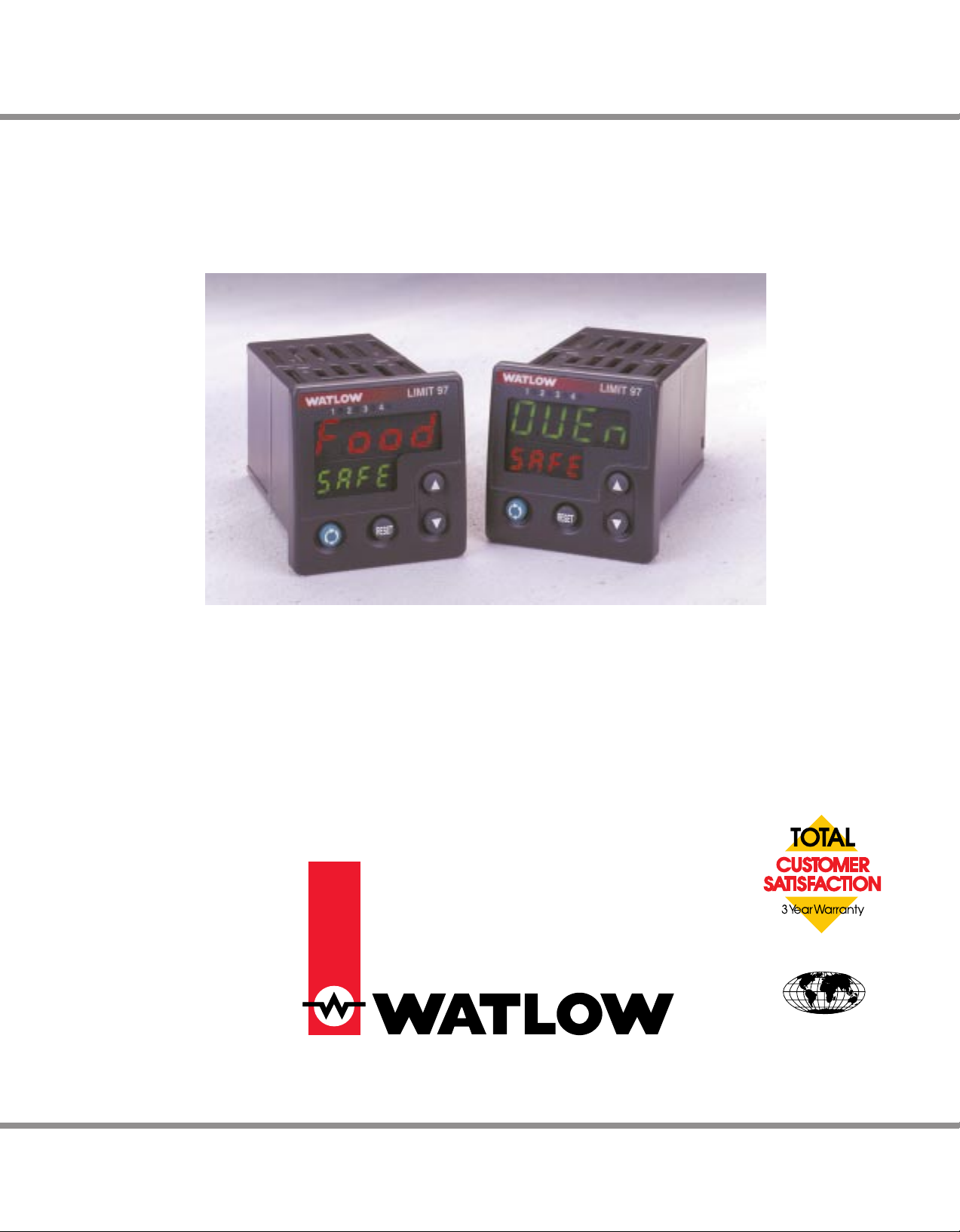
Series 97
User’s Manual
User Levels:
• New User ....................................................... go to page 1.1
• Experienced User .......................................... go to page 2.1
• Expert User .................................................... go to page 2.1
Installers:
• Installation ...................................................... go to page 2.1
• Wiring .............................................................go to page 3.1
Watlow Controls
1241 Bundy Blvd., P.O. Box 5580, Winona, Minnesota USA 55987-5580, Phone: (507) 454-5300, Fax: (507) 452-4507
WO97-XUMN Rev A Made in the U.S.A.
July 1997 $15.00

NOTE:
Details of a “Note”
appear here in the
narrow margin on the
outside of each page.
CAUTION:
Details of a
“Caution” appear
here in the narrow
margin on the outside of each page.
WARNING:
Details of a
“Warning” appear
here in the narrow
margin on the outside of each page.
Safety Information
We use note, caution and warning symbols throughout this book to draw your
attention to important operational and safety information.
A “NOTE” marks a short message in the margin to alert you to an important
detail.
A “CAUTION” safety alert appears with information that is important for protecting your equipment and performance. Be especially careful to read and follow all cautions that apply to your application.
A “WARNING” safety alert appears with information that is important for protecting you, others and equipment from damage. Pay very close attention to all
warnings that apply to your application.
The safety alert symbol, ç, (an exclamation point in a triangle) precedes a
general CAUTION or WARNING statement.
The electrical hazard symbol, Ó, (a lightning bolt in a triangle) precedes an
electric shock hazard CAUTION or WARNING safety statement.
Technical Assistance
If you encounter a problem with your Watlow controller, see the Troubleshooting Table in the Appendix and review all of your configuration information to verify that your selections are consistent with your application: inputs;
outputs; alarms; limits; etc. If the problem persists after checking the above,
you can get technical assistance from your local Watlow representative, or by
dialing (507) 454-5300.
An applications engineer will discuss your application with you.
Please have the following information available when calling:
• Complete model number • All configuration information
• User’s Manual • Diagnostic menu readings
Your Feedback
Your comments or suggestions on this manual are welcome. Please send them
to: Technical Writer, Watlow Controls, 1241 Bundy Blvd., P.O. Box 5580,
Winona, MN 55987-5580; phone: (507) 454-5300; fax: (507) 452-4507. The
Series 97 User’s Manual is copyrighted by Watlow Winona, Inc., © July 1997,
with all rights reserved. (1134)

T
Series 97
Table of Contents
Chapter 1: Overview . . . . . . . . . . . . . . . . . . . . . . .1.1
Chapter 2: Installation . . . . . . . . . . . . . . . . . . . . . .2.1
Chapter 3: Wiring . . . . . . . . . . . . . . . . . . . . . . . . . .3.1
Power Wiring . . . . . . . . . . . . . . . . . . . . . . . . .3.3
Sensor Installation Guidelines . . . . . . . . . . . .3.3
Wiring Example . . . . . . . . . . . . . . . . . . . . . . .3.4
Wiring Notes . . . . . . . . . . . . . . . . . . . . . . . . .3.5
Input 1 . . . . . . . . . . . . . . . . . . . . . . . . . . . . . .3.6
Input 2 . . . . . . . . . . . . . . . . . . . . . . . . . . . . . .3.6
Output 1 . . . . . . . . . . . . . . . . . . . . . . . . . . . . .3.7
Output 2 . . . . . . . . . . . . . . . . . . . . . . . . . . . . .3.8
Output 3 . . . . . . . . . . . . . . . . . . . . . . . . . . . . .3.9
Output 4 . . . . . . . . . . . . . . . . . . . . . . . . . . . . .3.10
Chapter 4: Software Navigation . . . . . . . . . . . . . . .4.1
Keys and Displays . . . . . . . . . . . . . . . . . . . . .4.2
Navigation . . . . . . . . . . . . . . . . . . . . . . . . . . .4.3
Software Map . . . . . . . . . . . . . . . . . . . . . . . . .4.4
Task Charts . . . . . . . . . . . . . . . . . . . . . . . . . . 4.6
Chapter 5: Features. . . . . . . . . . . . . . . . . . . . . . . . 5.1
Limit. . . . . . . . . . . . . . . . . . . . . . . . . . . . . . . . 5.2
Input . . . . . . . . . . . . . . . . . . . . . . . . . . . . . . .5.3
Alarms . . . . . . . . . . . . . . . . . . . . . . . . . . . . . .5.8
Communications . . . . . . . . . . . . . . . . . . . . . .5.11
Chapter 6: Parameters . . . . . . . . . . . . . . . . . . . . . 6.1
Home Page . . . . . . . . . . . . . . . . . . . . . . . . . .6.3
Operations Page . . . . . . . . . . . . . . . . . . . . . . 6.4
Setup Page . . . . . . . . . . . . . . . . . . . . . . . . . . 6.7
Factory Page . . . . . . . . . . . . . . . . . . . . . . . . . 6.17
Appendix. . . . . . . . . . . . . . . . . . . . . . . . . . . . . . . . A.1
Troubleshooting . . . . . . . . . . . . . . . . . . . . . . . A.2
Modbus™ RTU . . . . . . . . . . . . . . . . . . . . . . . A.4
Calibrating the Series 97 . . . . . . . . . . . . . . . . A.11
Glossary . . . . . . . . . . . . . . . . . . . . . . . . . . . . A.14
Specifications . . . . . . . . . . . . . . . . . . . . . . . . A.18
Ordering Information . . . . . . . . . . . . . . . . . . . A.20
Index. . . . . . . . . . . . . . . . . . . . . . . . . . . . . . . A.21
Prompt Index. . . . . . . . . . . . . . . . . . . . . . . . . A.23
Parameter Setup Order . . . . . . . . . . . . . . . . . A.24
Software Map . . . . . . . . . . . . . . . inside back cover
Warranty and Returns . . . . . . . . . . . . back cover
Figures and Tables
Inputs and outputs . . . . . . . . . . . . . . . . . . . . . . . . .1.1
Multiple panel cutout dimensions . . . . . . . . . . . . . .2.1
Installing the controller . . . . . . . . . . . . . . . . . . . . . .2.2a
Gap dimensions . . . . . . . . . . . . . . . . . . . . . . . . . . .2.2b
Removing the controller . . . . . . . . . . . . . . . . . . . . .2.3
Isolation blocks . . . . . . . . . . . . . . . . . . . . . . . . . . .3.2
Power wiring . . . . . . . . . . . . . . . . . . . . . . . . . . . . .3.3
Wiring example . . . . . . . . . . . . . . . . . . . . . . . . . . .3.4
Wiring notes . . . . . . . . . . . . . . . . . . . . . . . . . . . . .3.5
Input 1 Wiring
Thermocouple . . . . . . . . . . . . . . . . . . . . . . . .3.6a
RTD (2- or 3-Wire) 100Ω platinum . . . . . . . . .3.6b
Input 2 Wiring
Digital Event . . . . . . . . . . . . . . . . . . . . . . . . . .3.6c
Output 1 Limit Output Wiring
AC Outputs . . . . . . . . . . . . . . . . . . . . . . . . . .3.7a
Output 2 Alarm Output Wiring
AC Outputs . . . . . . . . . . . . . . . . . . . . . . . . . .3.8a
Switched DC, Open Collector . . . . . . . . . . . . . . . . .3.8b
Output 3 Alarm Wiring
AC Outputs . . . . . . . . . . . . . . . . . . . . . . . . . .3.9
Output 4 wiring
AC Outputs . . . . . . . . . . . . . . . . . . . . . . . . . .3.10a
Communications and Retransmit . . . . . . . . . .3.10b
EIA-232 to EIA-435 Conversion . . . . . . . . . . . . . . .3.11a
EIA-232 to EIA-485 Converter . . . . . . . . . . . .3.11b
Keys and displays . . . . . . . . . . . . . . . . . . . . . . . . .4.2
Navigating the Series 97 . . . . . . . . . . . . . . . . . . . .4.3
Software Map . . . . . . . . . . . . . . . . . . . . . . . . . . . .4.4
Calibration offset . . . . . . . . . . . . . . . . . . . . . . . . . .5.3
Filtered and unfiltered input signals . . . . . . . . . . . .5.4
Sensor ranges . . . . . . . . . . . . . . . . . . . . . . . . . . . .5.5
Event inputs . . . . . . . . . . . . . . . . . . . . . . . . . . . . . .5.6
Retransmitting a remote set point . . . . . . . . . . . . . .5.7
Alarm settings . . . . . . . . . . . . . . . . . . . . . . . . . . . .5.8
Alarm latching . . . . . . . . . . . . . . . . . . . . . . . . . . . .5.9
Alarm silencing . . . . . . . . . . . . . . . . . . . . . . . . . . .5.10
Parameter setup order . . . . . . . . . . . . . . . . . . . . . .6.2
. . . . . . . . . . . . . . . . . . . . . . . . . . . . .inside back cover

Meet the Series 97 Team
TOTAL
CUSTOMER
SATISFACTION
We stand behind our product and are committed to your total satisfaction.
Pictured below are some of the people at Watlow who have worked hard to bring
you one of the finest industrial temperature controllers available today. Included
in the photo are members of the development team, production team, and
representatives from our core manufacturing and customer service areas.
ii ■ Table of Contents Watlow Series 97
Front Row: Steve Lubahn, marketing; Dean McCluskey, engineer; Mark Wagner, engineer.
Second Row: Brian Clements, quality; Keith Ness, engineer; Craig Dennis, marketing; Rick Kompelien,
manufacturing engineer.
Third Row: Erin Benson, engineering technician; Lisa Voelker, engineering technician; Sally Kotschevar, purchasing;
Christina Baumgartner, production; Trish Johnson, production; Teresa Fakler, production.
Back Row: Pamela Eyden, technical writer; Stan Breitlow, engineer; John Pham, engineer; Steve Berekvam,
engineering technician; John Gabbert, technical writer; Larry Sevcik, engineer; Roger Ruehmann, applications
engineer; Kurt Peterson, engineer; Donna Foster, production; Tom Butler, test engineer; Kristin Gunderson,
production; Clara Kronebusch, customer service; Mary White, customer service; Donna Borkowski, field returns.
About Watlow Controls
Watlow Controls is a division of Watlow Electric Mfg. Co., St. Louis, Missouri, a
manufacturer of industrial electric heating products, since 1922. Watlow begins
with a full set of specifications and completes an industrial product that is
manufactured totally in-house, in the U.S.A.. Watlow products include electric
heaters, sensors, controllers and switching devices. The Winona operation has
been designing solid state electronic control devices since 1962, and has earned
the reputation as an excellent supplier to original equipment manufacturers.
These OEMs depend upon Watlow Controls to provide compatibly engineered
controls which they can incorporate into their products with confidence. Watlow
Controls resides in a 100,000 square foot marketing, engineering and
manufacturing facility in Winona, Minnesota.
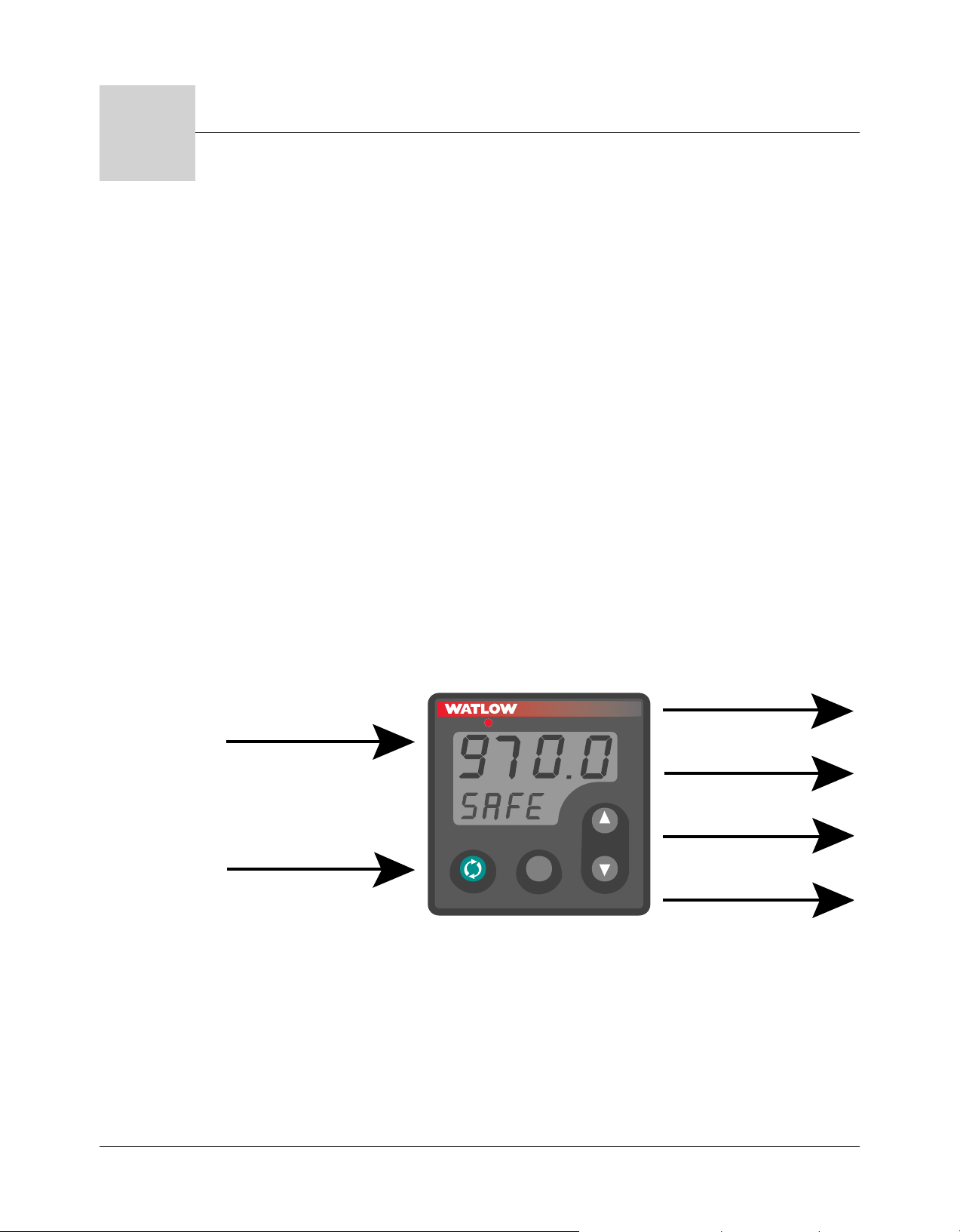
Input 1
Process
Input 2
Remote Reset or
Hardware Lockout
Output 1
Limit Relay
Output 2
Alarm
Output 3
Alarm
Output 4
Alarm, Analog or
Communications
234
LIMIT 97
1
RESET
1
Introduction
Chapter One
Overview
Watlow’s Series 97 is a microprocessor-based controller with a single input, second auxiliary
input and four outputs. Input 1 is used to measure temperature from a sensor. Input 2 can
be utilized as a remote reset switch or a hardware lockout switch. With up to four outputs,
the controller is versatile in handling applications that require a high/low limit, alarms,
retransmit and communications. The controller is so user friendly it can be set up to display
safety and limit messages created by the end user to meet the exact application need.
The Series 97 limit controller is added to thermal applications to limit over-temperature
conditions. The Series 97 controller provides safety assurance against instances where a
high temperature runaway condition could occur from a shorted input sensor or an output
device that could fail in a closed position.
The Series 97 is recommended for any application where thermal runaway could result in
large product scrap costs, affect operator safety, cause damage to equipment, or create a fire
hazard.
The Series 97 is manufactured by ISO 9001-registered Watlow Controls and reliably backed
by a three-year warranty.
Figure 1.1 — Series 97 inputs and outputs.
Watlow Series 97 Overview ■ 1.1

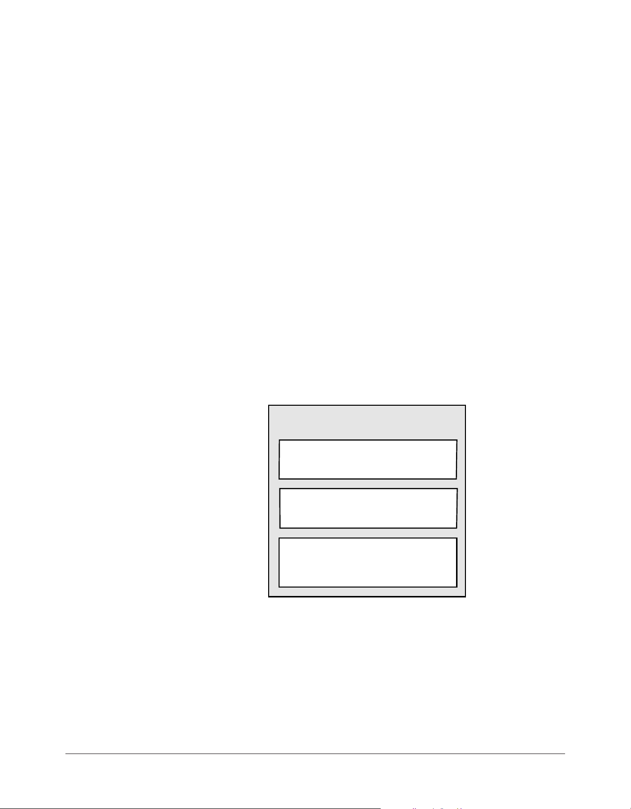
Setup Steps
How to do itWhat to do
Install the controller.
1
Wire the controller.
2
Configure the controller for
3
your application.
Set up communications.
4
See Chapter Two.
See Chapter Three.
Chapter Four explains the keys, displays and software
navigation.
Chapter Five explains features, such as alarms and
control methods.
Chapter Six lists parameter descriptions, ranges,
Modbus numbers and other information.
The controller must be equipped for communications,
(97_ _ - _ _ _ U - _ _ _ _ or 97_ _ - _ _ _ R - _ _ _ _).
See Chapter Five, Chapter Six and the Appendix.
1.2 ■ Overview Watlow Series 97

Panel Cutout
Panel
Thickness
0.06" to 0.38"
(1.5 to 9.7 mm)
1.77" to 1.79"
(44.96mm to 45.47mm)
1.77" to 1.79"
(44.96mm
to 45.47mm)
0.540"
(13.72mm)
Minimum
0.310"
(7.874mm)
2.050"
2.050"
234
LIMIT 97
1
RESET
2
Chapter Two
Installation
Figure 2.1 - Series 97 multiple panel cutout dimensions.
NOTE: Measurements between panel cutouts are the minimum recommended.
For rapid mounting, use Greenlee punch number 60020 and die number 60021, or hand hydraulic unit, kit number 7306,
all available from Grainger.
Watlow Series 97 Installation ■ 2.1

Installing the Series 97 Controller
.025 Maximum gap
Customer's Front Panel
Front Bezel
Mounting Collar
Retention Collar
Installing and mounting requires access to the back of the panel.
1. Make the panel cutout using the tear-out mounting template found on the previous
page, or the dimensions found in this chapter.
2. Check to see that the gasket is properly seated into the gasket channel on the front
bezel and that it is not twisted. Make sure that the rounded surface of the gasket is the
surface that is exposed from the gasket channel, as this is the surface that will mate to
the panel surface. Insert the controller into the panel cutout.
3. With the controller inserted into the panel cutout, take the retention collar and slide it
over the controller, making certain that the two locating holes in the retention collar are
visible from the rear of the controller, with one hole pointing up and one pointing down.
Then, take the mounting collar and slide it over the controller, making certain that one
cantilever is pointing up and one is pointing down also. With one hand holding the controller and the other hand using a #2 Phillips screw driver, tighten the two screws in
the mounting collar until the gap between the bezel and panel surface is .025” maximum. See figure below. Make sure that you cannot move the controller back and forth
in the cutout. If you can, you do not have a proper seal.
Figure 2.2a - Installing the controller. Figure 2.2b - Series 97 gap dimensions.
ç
CAUTION: Follow the installation procedure exactly to guarantee a proper NEMA 4X seal. Make sure the gasket between
the panel and the rim of the case is not twisted and is seated properly. Failure to do s o could result in damage to equipment.
NOTE: Be careful not to over-tighten the screws. This may cause the mounting cover to fail. Over-tightening occurs when
the front bezel is touching the customer’s front panel.
2.2 ■ Installation Watlow Series 97

Removing the Series 97 Controller
1 Hold the controller with one hand while using the other hand to loosen the screws with
a #2 Phillips screwdriver until the end of the screw is flush or past the end of the cantilevers, see the figure below.
2. After the screws have been loosened, hold the controller with one hand while squeezing
the two screws together with the other hand. Then simply slide the mounting collar off
the controller.
Figure 2.3 - Removing the controller.
Watlow Series 97 Installation ■ 2.3

Notes
2.4 ■ Installation Watlow Series 97

3
Chapter Three
Wiring
Power Wiring . . . . . . . . . . . . . . . . . . . . . .3.3
Sensor Installation Guidelines . . . . . . . . .3.3
Wiring Example . . . . . . . . . . . . . . . . . . . .3.4
Wiring Notes . . . . . . . . . . . . . . . . . . . . . .3.5
Input 1 . . . . . . . . . . . . . . . . . . . . . . . . . . .3.6
Input 2 . . . . . . . . . . . . . . . . . . . . . . . . . . .3.6
Output 1 Limit Output Wiring . . . . . . . . . .3.7
Output 2 Alarm Output Wiring . . . . . . . . .3.8
Output 3 Alarm Wiring . . . . . . . . . . . . . . .3.9
Output 4 . . . . . . . . . . . . . . . . . . . . . . . . .3.10
EIA Conversions . . . . . . . . . . . . . . . . . . .3.11
Watlow Series 97 Wiring ■ 3.1
∫
Input 1
Input 2
Output 1
Output 2
Output 3
Output 4 (unless Output 4 is used for communications)
Output 4 (if Output 4 is used for communications)
Isolation Blocks
There are no electrical connections between these blocks.
INPUT
OUTPUT
COMMUNICATIONS
WARNING:
To avoid potential
electric shock, use
National Electric Code
(NEC) safety practices
when wiring and
connecting this unit to a
power source and to
electrical sensors or
peripheral devices.
Failure to do so could
result in injury or death.
Wiring the Series 97
Wiring options depend on the model number. Check the terminal
designation stickers on either side of the controller and compare
your model number to those shown here and with the model
number breakdown on the inside back cover of this manual.
NOTE: Using the Diagnostics Menu (Factory Page) check
Output 1 Hardware through Output 4 Hardware, [Oty1]
through [Oty4]. See Chapter Six for information about the
menu and range of settings for each output. These outputs may
differ from those listed for the model number on the controller
and described in this manual, indicating a customized hardware
setup.
Input-to-output Isolation
The Series 97 uses optical and transformer isolation between the
analog inputs and the controller outputs, including the
communications interface. This isolation provides a barrier to
prevent ground loops when using grounded sensors and/or
peripheral equipment.
Here is a breakdown of the isolation barriers:
• Analog inputs 1 and 2 are grouped together.
• Outputs 1 through 4 are grouped together. This does not
apply to Output 4 when it is configured for communications.
• If Output 4 is configured for communications, it is isolated
from the the other inputs and outputs.
3.2 ■ Wiring Watlow Series 97
Figure 3.2 — Isolation blocks.

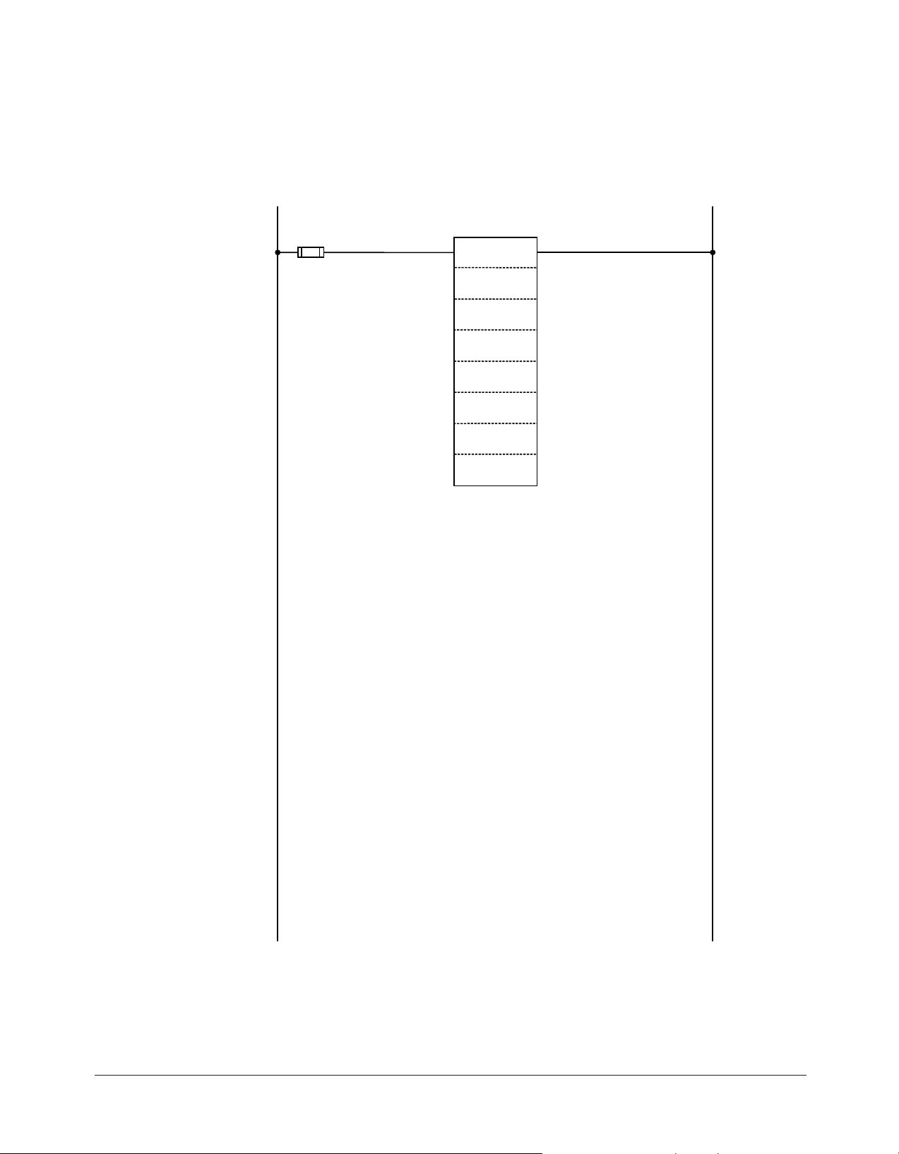
Power Wiring
10
8
1
2
3
4
5
6
7
13 14 15
11
12
16 17 18
19 20 21
Fuse
L2
L1
-
9
8
9
+
ç
CAUTION:
If high voltage is applied
to a low-voltage unit,
irreversible damage will
occur.
ç∫
WARNING:
To avoid damage to
property and equipment,
and/or injury of loss of
life, use National Electric
Code (NEC) standard
wiring practices to install
and operate the Series
97. Failure to do so could
result in such damage,
and/or injury or death.
ç
CAUTION:
Maintain isolation
between input 1 and
input 2 to prevent a
ground loop. A ground
loop may cause incorrect
readings, dashes across
the upper display or the
display of error codes.
Failure to follow this
guideline could result in
damage to equipment.
100 to 240VÅ (ac), nominal (85 to 264 actual) 97 A _ - _ _ _ _ - _ _ _ _
24 to 28V‡ (ac/dc), nominal (21 to 30 actual) 97 B _ - _ _ _ _ - _ _ _ _
Figure 3.3 - Power wiring.
Sensor Installation Guidelines
Thermocouple inputs: Extension wire for thermocouples must
be of the same alloy as the thermocouple to limit errors.
When using a voltage input for the digital event on Input 2, use
an ungrounded thermocouple on Input 1. If a grounded
thermocouple is required, the signal to input 2 must be isolated
to prevent possible ground loops.
RTD input: Each 1Ω of lead wire resistance can cause a +2°F
error when using a two-wire RTD. Athree-wire RTD sensor
overcomes this problem. All three wires must have the same
electrical resistance (i.e., same gauge, same length, multistranded or solid, same metal).
Watlow Series 97 Wiring ■ 3.3

Wiring Example
1
120VÅ (ac)
L1
L2
2
7
6
4
5
1 2
1
2
(+)
(-)
3
13
20
14
15
16
17
2
1CR
18
high-temperature light
1
2
3
4
8
9
10
11
12
R
19
1
8
(+) (-)
1 CR-1
9
10
2
15 13
67
9 8
5
6
7
Series 96
96A0 - CAAA - 00RR
Temperature Controller
Series 97
97A1-DDAA-00RR
Limit Controller
13
14
15
16
6
98
1
3
7
(+)
(-)
Heater
DIN-a-mite
DA1C-1624-C000
L2L1
T1
T2
11 12
1
17
96AO-CAAA-OORR
rear view
6 (-)
7 (+)
8
15 (+)
13 (-)
L1
L2
120VÅ (ac)
fuse
97A1-DDAA-00RR
Limit Controller
process sensor
limit sensor
optional
normally open
momentary switch
high limit
mechanical
contactor
7 (+)
6 (-)
high
temperature
light
coil
9
Heater
DIN-a-mite
DA1C-1624-C000
L2L1
T1
T2
10
8
1
2
3
4
5
6
7
13 14 15
11
12
16 17 18
19 20 21
9
10
8
1
2
3
4
5
6
7
13 14 15
11
12
16 17 18
19 20 21
9
1
3
14 15
17
9
16
∫ç
WARNING:
To avoid potential
electric shock and
damage to property and
equipment, use National
Electric Code (NEC)
safety practices when
wiring and connecting
this unit to a power
source and to electrical
sensors or peripheral
devices. Failure to do so
could result in injury or
death.
ç
WARNING:
Install high or low
temperature limit control
protection in systems
where an over
temperature fault
condition could present a
fire hazard or other
hazard. Failure to install
temperature limit control
protection where a
potential hazard exists
could result in damage to
equipment, property and
injury to personnel.
3.4 ■ Wiring Watlow Series 97
Figure 3.4 - System wiring example.
Wiring Notes
L1 L2
power
98
∫ç
WARNING:
To avoid damage to
property and equipment,
and/or injury of loss of
life, use National Electric
Code (NEC) standard
wiring practices to
install and operate the
Series 97. Failure to do
so could result in such
damage, and/or injury or
death.
Sketch in your application on this page or a copy of it. See the
wiring example in this chapter.
Figure 3.5 - Wiring notes.
Watlow Series 97 Wiring ■ 3.5

10
8
1
2
3
4
5
6
7
13 14 15
11
12
16 17 18
19 20 21
9
3
1
+
-
2.67kΩ
EVENT +
3
EVENT
-
1
20kΩ
100Ω
+5V
1
2
3
4
5
6
7
1
5
6
7
S1
S2
S3
3-wire
1
2
3
4
5
6
7
6
7
S1
S3
5
2-wire
jumper 5 to 6
10
8
1
2
3
4
5
6
7
13 14 15
11
12
16 17 18
19 20 21
9
- 6
+7
Input 1 Wiring
NOTE:
Successful installation
requires five steps:
• Choose the controller’s
hardware configuration
Figure 3.6a – Thermocouple
Available on all units
Impedance: 20MΩ
and model number
(Appendix);
• Choose a sensor
(Chapters 3 and 6, and
Appendix);
• Install the controller
(Chapter 2);
• Wire the controller
(Chapter 3) and
Figure 3.6b – RTD (2- or 3-Wire) 100Ω Platinum
Available on all units
• Configure the controller
(Chapters 4, 5 and 6).
ç
WARNING:
To avoid damage to
property and equipment,
and/or injury of loss of
life, use National Electric
Code (NEC) standard
wiring practices to
install and operate the
Series 97. Failure to do
so could result in such
damage, and/or injury or
death.
ç
CAUTION:
Maintain isolation
between input 1 and
input 2 to prevent a
ground loop. A ground
loop may cause incorrect
readings, dashes across
the upper display or the
display of error codes.
Failure to follow this
guideline could result in
damage to equipment
and product.
3.6 ■ Wiring Watlow Series 97
Input 2 Wiring
Figure 3.6c – Digital Event
97 _ 1 - _ _ _ _ - _ _ _ _
Voltage input
3-36VÎ (dc) Event Input High State
0-2VÎ (dc) Event Input Low State
Contact closure
0-2kΩ Event Input Low State
> 23kΩ Event Input High State
10
8
1
2
3
4
5
6
7
13 14 15
11
12
16 17 18
19 20 21
9
External
Load
1514
COM. N.O.
L2
L1
(13 used for
D outputs only)
13
N.C.
customer-supplied
Quencharc
NOTE:
Successful installation
requires five steps:
• Choose the controller’s
hardware configuration
and model number
(Appendix);
• Choose a sensor
(Chapters 3 and 6, and
Appendix);
• Install the controller
(Chapter 2);
• Wire the controller
(Chapter 3) and
• Configure the controller
(Chapters 4, 5 and 6).
ç
WARNING:
To avoid damage to
property and equipment,
and/or injury of loss of
life, use National Electric
Code (NEC) standard
wiring practices to
install and operate the
Series 97. Failure to do
so could result in such
damage, and/or injury or
death.
NOTE:
Switching inductive loads
(relay coils, solenoids,
etc.) with the mechanical
relay, switched dc or
solid-state relay output
options requires use of
an R.C. suppressor.
Watlow carries the R.C.
suppressor Quencharc
brand name, which is a
trademark of ITW Pakron.
Watlow Part No. 08040147-0000.
Output 1 Limit Output Wiring
Figure 3.7a – AC Outputs
•Electromechanical Relay without
contact suppression
97 _ _ - D _ _ _ - _ _ _ _
Form C, 2 amps, off-state
impedance: 31MΩ
Watlow Series 97 Wiring ■ 3.7

+VÎ (dc)
Internal Circuitry
16
18
17
22 to 28VÎ (dc)
10
8
1
2
3
4
5
6
7
13 14 15
11
12
16 17 18
19 20 21
9
+ 16 17 18 -
External
Load
COM.
Switched DC
10
8
1
2
3
4
5
6
7
13 14 15
11
12
16 17 18
19 20 21
9
External
Load
COM. N.C.
L2
L1
16 17 18 (18 used for
D outputs only)
N.O.
customer-supplied
Quencharc
NOTE:
Successful installation
requires five steps:
• Choose the controller’s
hardware configuration
and model number
(Appendix);
• Choose a sensor
(Chapters 3 and 6, and
Appendix);
• Install the controller
(Chapter 2);
• Wire the controller
(Chapter 3) and
• Configure the controller
(Chapters 4, 5 and 6).
NOTE:
Switching inductive loads
(relay coils, solenoids,
etc.) with the mechanical
relay, switched dc or
solid-state relay output
options requires use of
an R.C. suppressor.
Watlow carries the R.C.
suppressor Quencharc
brand name, which is a
trademark of ITW Pakron.
Watlow Part No. 08040147-0000.
Output 2 Alarm Output Wiring
Figure 3.8a – AC Outputs
•Electromechanical relay without contact suppression
97 _ _ - _ D _ _ _ - _ _ _ _
Form C, 2 amps, off-state
impedance: 31MΩ
•Solid-state relay without
contact suppression
97 _ _ - _ K _ _ - _ _ _ _
0.5 amps, off-state
impedance: 31MΩ
Figure 3.8b – Switched DC, Open Collector
97 _ _ - _ C _ _ - _ _ _ _
Switched DC
configuration:
Maximum voltage:
28VÎ (dc)
Maximum current:
30mA
Open collector configuration:
Maximum voltage: 42VÎ (dc)
Maximum current: 200 mA
ç
WARNING:
To avoid damage to
property and equipment,
and/or injury of loss of
life, use National Electric
Code (NEC) standard
wiring practices to
install and operate the
Series 97. Failure to do
so could result in such
damage, and/or injury or
death.
3.8 ■ Wiring Watlow Series 97

10
8
1
2
3
4
5
6
7
13 14 15
11
12
16 17 18
19 20 21
9
External
Load
L2
L1
11
10
N.C.
N.O.
12
COM.
customer-supplied
Quencharc
NOTE:
Successful installation
requires five steps:
• Choose the controller’s
hardware configuration
and model number
(Appendix);
• Choose a sensor
(Chapters 3 and 6, and
Appendix);
• Install the controller
(Chapter 2);
• Wire the controller
(Chapter 3) and
• Configure the controller
(Chapters 4, 5 and 6).
NOTE:
Switching inductive loads
(relay coils, solenoids,
etc.) with the mechanical
relay, switched dc or
solid-state relay output
options requires use of
an R.C. suppressor.
Watlow carries the R.C.
suppressor Quencharc
brand name, which is a
trademark of ITW Pakron.
Watlow Part No. 08040147-0000.
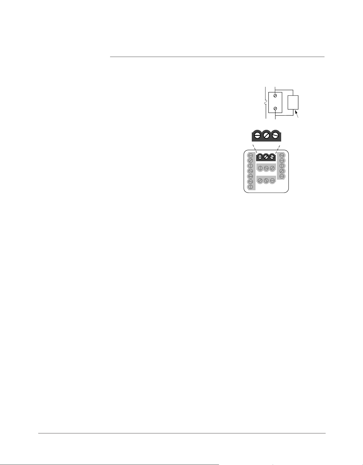
Output 3 Alarm Wiring
Figure 3.9 – AC Outputs
Electromechanical Relay without Contact Suppression
97 _ _ - _ _ D_ - _ _ _ _
Form C, 2 amps, off-state impedance: 31MΩ
ç
WARNING:
To avoid damage to
property and equipment,
and/or injury of loss of
life, use National Electric
Code (NEC) standard
wiring practices to
install and operate the
Series 97. Failure to do
so could result in such
damage, and/or injury or
death.
Watlow Series 97 Wiring ■ 3.9
10
8
1
2
3
4
5
6
7
13 14 15
11
12
16 17 18
19 20 21
9
19 20 21
V out COM. I out
10
8
1
2
3
4
5
6
7
13 14 15
11
12
16 17 18
19 20 21
9
19 20 21
T-/R- COM. T+/R+
10
8
1
2
3
4
5
6
7
13 14 15
11
12
16 17 18
19 20 21
9
19 20 21
T out COM. R in
10
8
1
2
3
4
5
6
7
13 14 15
11
12
16 17 18
19 20 21
9
External
Load
COM. N.C.
L2
L1
19 20 21
N.O.
customer-supplied
Quencharc
NOTE:
Successful installation
requires five steps:
• Choose the controller’s
hardware configuration
and model number
(Appendix);
• Choose a sensor
(Chapters 3 and 6, and
Appendix);
• Install the controller
(Chapter 2);
• Wire the controller
(Chapter 3) and
• Configure the controller
(Chapters 4, 5 and 6).
NOTE:
Switching inductive loads
(relay coils, solenoids,
etc.) with the mechanical
relay, switched dc or
solid-state relay output
options requires use of
an R.C. suppressor.
Watlow carries the R.C.
suppressor Quencharc
brand name, which is a
trademark of ITW Pakron.
Watlow Part No. 08040147-0000.
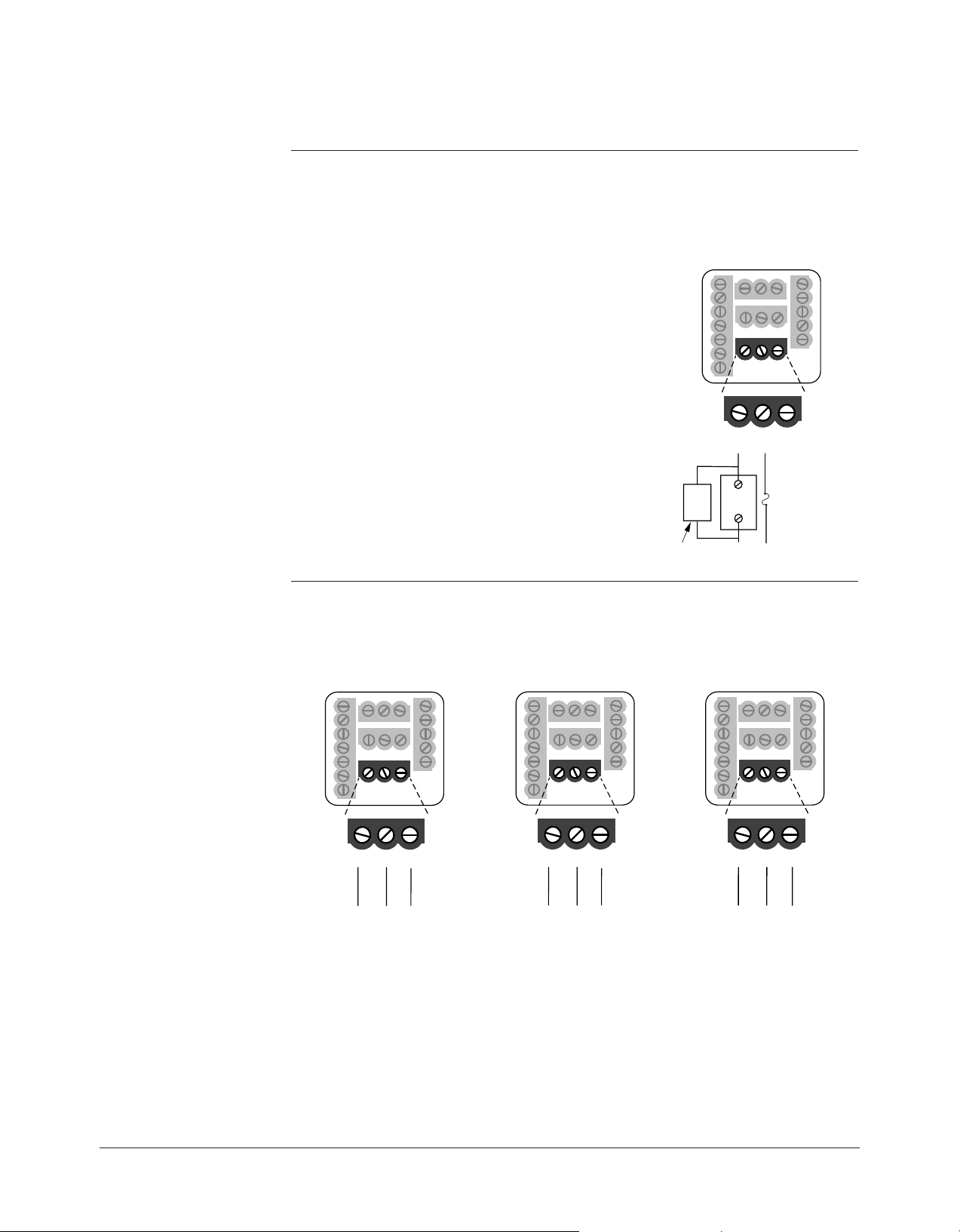
Output 4 Wiring
Figure 3.10a – AC Outputs
Electromechanical Relay without Contact Suppression
97 _ _ - _ _ _ D - _ _ _ _
Form C, 2 amps, off-state impedance: 31MΩ
Figure 3.10b – Communications and Retransmit Option
EIA/TIA-232 EIA/TIA-485 Retransmit Option
97 _ _ - _ _ _ R - _ _ _ _ 97 _ _ - _ _ _ U - _ _ _ _ 97_ _ - _ _ _ M - _ _ _ _
ç
WARNING:
To avoid damage to
property and equipment,
and/or injury of loss of
life, use National Electric
Code (NEC) standard
wiring practices to
install and operate the
Series 97. Failure to do
so could result in such
damage, and/or injury or
death.
3.10 ■ Wiring Watlow Series 97
NOTE:
+5V
B
A
GND
T+/R+
T-/R-
Com
1KΩ
120Ω
1KΩ
Converter box
termination
with pull-up
and pull-down
resistors.
9VÎ (dc) (see note)
120VÅ (ac)
COM.
T+/R+
T-/R-
0219-0217-0000
7 ft. comms cable
EIA-232
ADA485L
EIA-485
A
B
A
B
G
9VÎ
G
DI/ODI/O
19
21
20
T-/R-
TD (A)
TD (B)
RD (A)
RD (B)
GND
TD (A)
TD (A)
T+/R+
120V~ (ac)
EIA-232
EIA-485
EIA-485
Power Supply
AD-1210
+
–
GND
+12V
COM.
19
21
20
485OIC
Successful installation
requires five steps:
• Choose the controller’s
hardware configuration
and model number
(Appendix);
• Choose a sensor
(Chapters 3 and 6, and
Appendix);
• Install the controller
(Chapter 2);
• Wire the controller
(Chapter 3) and
• Configure the controller
(Chapters 4, 5 and 6).
ç
WARNING:
To avoid damage to
property and equipment,
and/or injury of loss of
life, use National Electric
Code (NEC) standard
wiring practices to
install and operate the
Series 97. Failure to do
so could result in such
damage, and/or injury or
death.
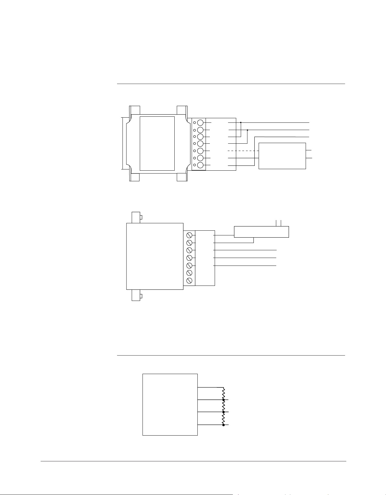
Figure 3.11a — EIA-232 to EIA-485 Conversion
B&B Converter (B&B Electronics Manufacturing Company, (815) 433-5100).
CMC Converter (CMC Connecticut Micro-Computer, Inc., 800-426-2872).
NOTE:
The CMC converter requires an external power supply when used with a laptop computer.
Figure 3.11b — Termination for EIA-232 to EIA-485 Converter
Watlow Series 97 Wiring ■ 3.11

Notes
3.12 ■ Wiring Watlow Series 97

4
Chapter Four
Navigation and Software
Keys and Displays . . . . . . . . . . . . . . . . . .4.2
Navigation . . . . . . . . . . . . . . . . . . . . . . . .4.3
Software Map . . . . . . . . . . . . . . . . . . . . .4.4
Task Charts . . . . . . . . . . . . . . . . . . . . . . .4.6
Watlow Series 97 Navigation ■ 4.1
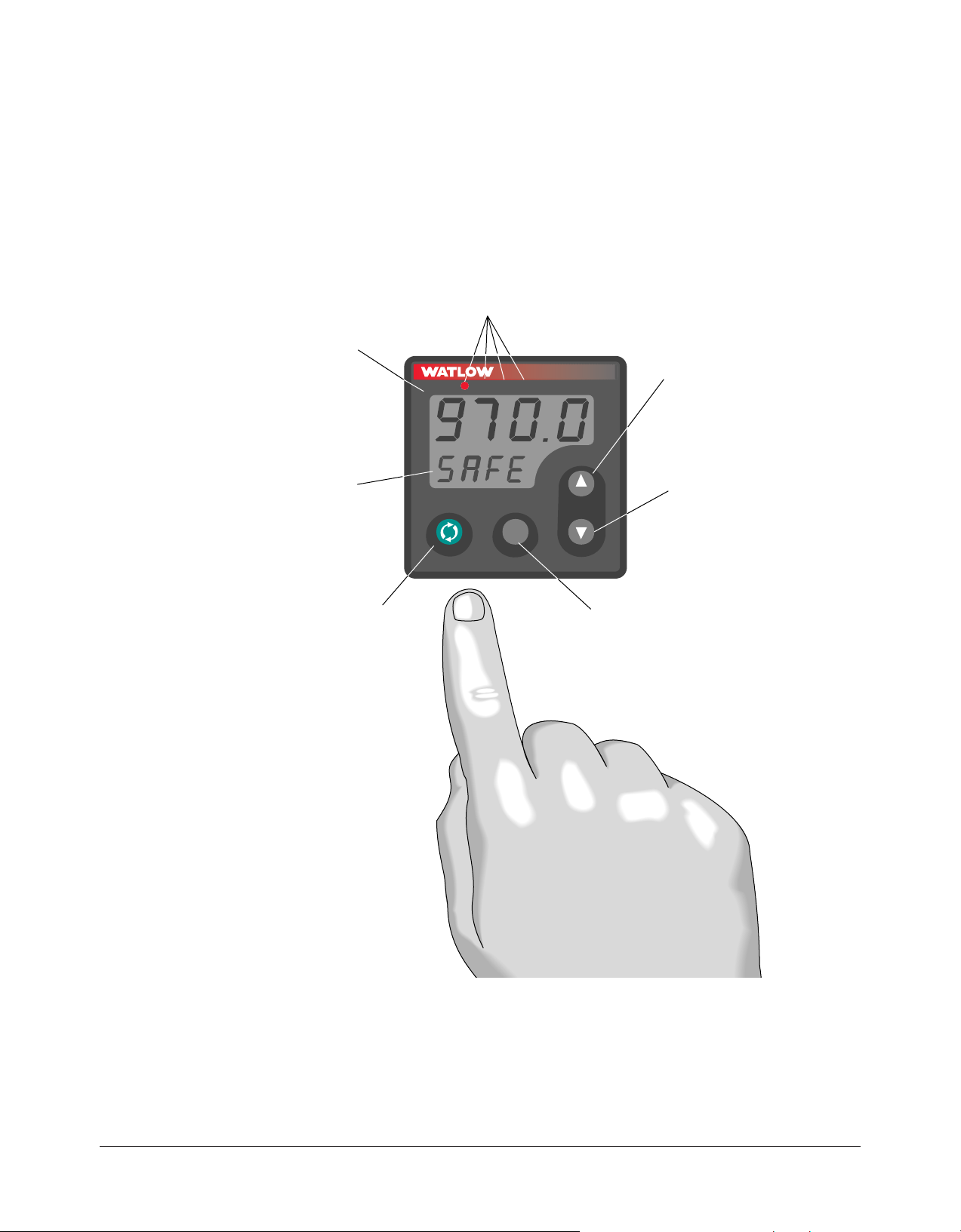
Keys and Displays
234
LIMIT 97
1
Active Output (1-4) Indicator Lights:
Lit when the corresponding output trips.
Indicator light next to number 4 will
flicker during communications activity if
the communications option is used.
Reset Key:
• Returns to the
Home Page
(process/actual
display).
• Resets an alarm.
• Resets an input
sensor error.
• Resets the limit.
Down Key:
Changes the upper
display to a lower
value, or down
through a list of
values. Moves from
menu to menu in a
page.
Up Key:
Changes the upper
display to a higher
value, or up through
a list of values.
Moves from menu to
menu in a page.
Upper Display:
Indicates actual
process values
during operation,
the value for the
parameter in the
lower display, or the
user programmed
message.
Advance Key:
Advances the lower
display through the
parameters.
To reverse direction,
press and hold ‰
while repeatedly
pressing the ¿ key.
RESET
Lower Display:
Indicates factory
programmed
message during
operation, the value
for the parameter in
the lower display, or
the user programmed
message.
This chapter explains keys, displays and navigation skills, and presents charts showing how
to accomplish basic and advanced tasks. You’ll also find a complete software map.
Figure 4.2 — Series 97 keys and displays.
4.2 ■ Navigation Watlow Series 97
Navigating the Series 97
• Operations Page: press ¿ and ¯ keys together for three seconds.
•
Home Page:
From anywhere, press the Reset Key.
RESET
RESET
RESET
RESET
RESETRESET
RESET
RESET
• Factory Page: press ‰ and Reset keys together for six seconds.
• Setup Page: press ¿ and ¯ keys together for six seconds.
Choose a page (Operations, Setup or Factory) and press its key sequence. The page appears
in the lower display.
1
1
1
234
234
234
LIMIT 97
LIMIT 97
LIMIT 97
1
1
1
234
234
234
LIMIT 97
LIMIT 97
LIMIT 97
LIMIT 97
234 %
1
Figure 4.3 — Navigating the Series 97.
Press ¯ or ¿ to find a specific menu in a page. The menu appears in the upper display and
the page remains in the lower display.
Press ‰ to enter the list of paramenters in the menu displayed. The menu’s parameters
appear in the lower display and the values in the upper. To go backward through the
parameter list press ‰ and ¿ together.
Press ¯ or ¿ to select a value, either alpha or numeric.
Press ‰ to set the value and go to the next parameter.
1
234
LIMIT 97
Watlow Series 97 Navigation ■ 4.3

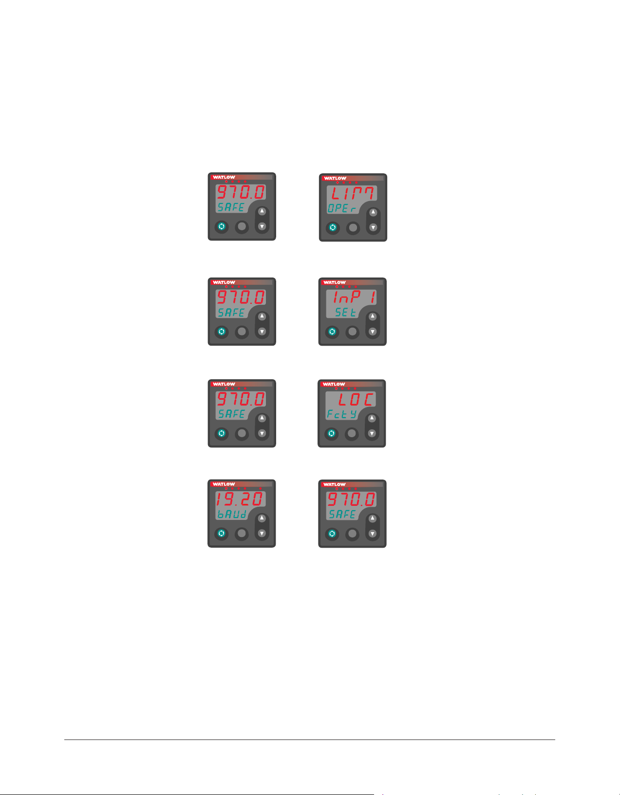
Navigation
[LIM] Limit Menu
[OPEr]
Operations Page
[OPEr] Operations Page
[L`Lo] Low Limit Set Point
[L`hi] High Limit Set Point
[CAL1] Calibration Offset
[OPEr] Operations Page
[Pr1`] Process 1
[L`St] Limit Status
[AL`2] Alarm 2 Status
[AL`3] Alarm 3 Status
[AL`4] Alarm 4 Status
[E`St] Event Input Status
[OPEr] Operations Page
[A2Lo] Alarm 2 Low
[A2hi] Alarm 2 High
[A3Lo] Alarm 3 Low
[A3hi] Alarm 3 High
[A4Lo] Alarm 4 Low
[A4hi] Alarm 4 High
‰
‰
‰
¿
¿
[Mon] Monitor Menu
[OPEr]
[ALM] Alarm Menu
[OPEr]
¯
¯
[``97] Process Value
[safe]
Home Page
Limit Status
[``97] Process Value
[Safe]
Limit Status
[LIM] Limit Menu
[OPEr]
Operations Page
[InP1] Input 1 Menu
[`SEt] Setup Page
[`LOC] Custom Menu
[FctY] Factory Page
Home Page
¿ and ¯
for 3 seconds
Operations Page
Setup Page
Factory Page
¿ and ¯
for 3 seconds
‰ and RESET
for 6 seconds
¿ to cycle through menus
‰ to select a parameter in a menu
¿ to select a value
‰ to enter a value and go to the next parameter
RESET anytime to return to the Home Page
Software Map
Figure 4.4 — Software Map.
4.4 ■ Navigation Watlow Series 97

[InP1] Input 1 Menu
[`SEt]
Setup Page
[`SEt] Setup Page
[SEn1] Sensor Type 1
[In`1] Input 1
[rL`1] Range Low 1
[rh`1] Range High 1
[dEC1] Decimal 1
[Ftr1] Input Software Filter 1
[`SEt] Setup Page
[In`2] Input 2
[E`Fn] Event Function
[E`cn] Event Condition
[`SEt] Setup Page
[LSid] Set Limit Active Sides
[LhYS] Limit Hysteresis
[`SEt] Setup Page
[Ot`2] Output 2
[hys2] Alarm Hysteresis 2
[LAt2] Latching 2
[SiL2] Silencing 2
[Sid2] Alarm Active Sides 2
[Lgc2] Alarm Logic 2
[Anu2] Alarm Annunciation 2
[`SEt] Setup Page
[Ot`3] Output 3
[hys3] Alarm Hysteresis 3
[LAt3] Latching 3
[SiL3] Silencing 3
[Sid3] Alarm Active Sides 3
[Lgc3] Alarm Logic 3
[Anu3] Alarm Annunciation 3
[`SEt] Setup Page
[Ot`4] Output 4
[hys4] Alarm Hysteresis 4
[LAt4] Latching 4
[SiL4] Silencing 4
[Sid4] Alarm Active Sides 4
[Lgc4] Alarm Logic 4
[Anu4] Alarm Annunciation 4
[Aout] Analog Output 4
[Prc4] Process 4 Type
[A`hi] Analog Output High
[A`Lo] Analog Output Low
[ACAL] Analog Output Offset
[BaUd] Baud Rate
[Addr] Address
[Udsp] Upper Display
[UP`L] Upper Display
User Limit Message
[Ldsp] Lower Display
[Lo`S] Lower Display
User Safe Message
[Lo`L] Lower Display
User Limit Message
[`SEt] Setup Page
[`C-F] C or F
[`Err] Input Error Latching
‰
‰
‰
‰
‰
‰
¿
¿
¿
¿
¿
¿
[InP2] Input 2 Menu
[`SEt]
[Out1] Output 1 Menu
[`SEt]
[Out2] Output 2 Menu
[`SEt]
[Out3] Output 3 Menu
[`SEt]
[Out4] Output 4 Menu
[`SEt]
‰
‰
[Disp] Display Menu
[`SEt]
[GLbL] Global Menu
[`SEt]
¯
¯
¯
¯
¯
¿
¯
¯
Factory Page
‰
‰
[Fcty] Factory Page
[OPEr] Operations Page Mode
[`SEt] Setup Page Lock
[`CAL] Calibration Menu Lock
[Fcty] Factory Page
[MdL] Model Number
[dAtE] Date of Manufacture
[`Sn1] Serial Number 1
[`Sn2] Serial Number 2
[Soft] Software ID Number
[`rEu] Software Revision
[Ity2] Input 2 Hardware Enabled
[Oty1] Output 1 Hardware
[Oty2] Output 2 Hardware
[Oty3] Output 3 Hardware
[Oty4] Output 4 Hardware
[tout] Test Output
[dISP] Test Displays
[hrES] High Resolution
[AMb] Ambient T emperature
[Acnt] Ambient A-D Counts
[cnt1] Channel 1 A-D Counts
[cnt2] Channel 2 A-D Counts
[tSht] Communication T est /
Troubleshooting
[Line] Line Frequency
¿
[`LOC] Lockout Menu
[FctY]
[dIAg] Diagnostics Menu
[FctY]
¯
Watlow Series 97 Navigation ■ 4.5
Note: The Factory Page also includes calibration
parameters that are not necessary for everyday use of
the controller. Calibration parameters and procedures
are explained in the Appendix.
 Loading...