

Page 1
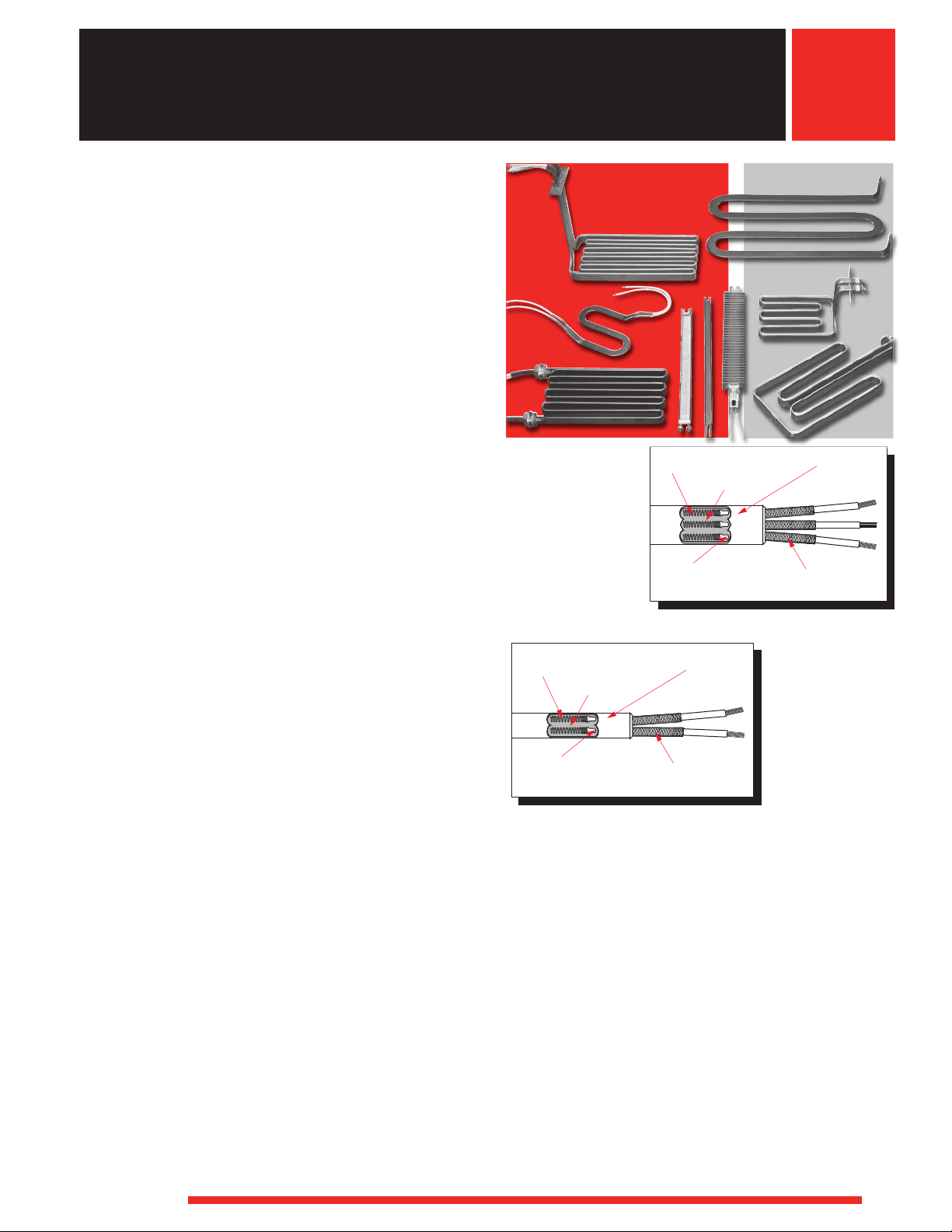
Tubular Heaters
Nickel-Chromium
Resistance Wire
Wire to Pin 360˚
Fusion Weld
Metal Sheath
MgO Insulation
Flexible Lead Wires
Nickel-Chromium
Resistance Wire
Wire to Pin 360°
Fusion Weld
Metal Sheath
MgO Insulation
Flexible Lead Wires
FIREBAR®Single/Double-Ended Heaters
FIREBAR®heating elements provide added heating
performance over standard round tubular heating
elements—especially for immersion applications in
petroleum based liquids requiring high kilowatts.
The FIREBAR’s unique flat surface geometry packs more
power in shorter elements and assemblies, along with a
host of other performance improvements. These include:
• Minimizing coking and fluid degrading
• Enhancing the flow of fluid past the element’s surface
• Improving heat transfer with a significantly larger
FIREBAR elements are available in single- and
double-ended constructions with one inch or
5
⁄8 inch heights. These two configuration variables make
it possible to use FIREBAR elements instead of round
tubular elements in virtually all applications.
FINBAR™ is a special version of the one inch,
single-ended FIREBAR. FINBAR is specially modified
with fins to further increase surface area for air and
gas heating applications. Details are contained in the
FINBAR section, starting on page 110.
Double-Ended Performance Capabilities
One Inch
• Watt densities to 120 W/in2(18.6 W/cm2)
• Incoloy®sheath temperatures to 1400°F (760°C)
• 304 stainless steel sheath temperatures to
• Voltages to 240VAC
• Amperages to 48 amperes per heater or 16 amperes
5
⁄8 Inch
• Watt densities to 90 W/in2(13.9 W/cm2)
• Incoloy®sheath temperatures to 1400°F (760°C)
• Voltages to 240VAC
• Amperages to 32 amperes per heater or 16 amperes
to carry heat from the sheath
boundary layer allowing much more liquid to flow up
and across the sheath’s surface
1200°F (650°C)
per coil
per coil
One Inch Double-Ended FIREBAR Element and
5
⁄8 Inch Double-Ended FIREBAR Element and
Lead Configurations
Lead Configurations
Single-Ended Performance Capabilities
One Inch
• Watt densities to 60 W/in2(9.3 W/cm2)
• Incoloy®sheath temperatures to 1400°F (760°C)
• 304 stainless steel sheath temperatures to
1200°F (650°C)
• Voltages to 240VAC
• Amperages to 48 amperes per heater or 16 amperes
per coil
5
⁄8 Inch
• Watt densities to 80 W/in2(12.4 W/cm2)
• Incoloy®sheath temperatures to 1400°F (760°C)
• Voltages to 240VAC
• Amperages to 16 amperes per heater
WATLOW
®
91
Page 2

Tubular Heaters
FIREBAR Double-Ended Heaters
Specifications
Applications Direct immersion; water, oils, etc. Direct immersion; water, oils, etc.
Clamp-on; hoppers, griddles Clamp-on; hoppers, griddles
Forced air heating (Also see FINBAR, page 110) Forced air heating
Radiant heating Radiant heating
Watt Density Stock: up to 90 (13.9) Stock: up to 90 (13.9)
W/in2(W/cm2) Made-to-Order (M-t-O): up to 120 (18.6) Made-to-Order (M-t-O) up to 90 (13.9)
Surface Area Per Linear In. (cm) 2.3 in2(14.8 cm2) 1.52 in2(9.80 cm2)
Cross Section
Height 1.010 (25.7) 0.650 (16.5)
± 0.015/0.010 in. (0.381/0.254 mm)
Thickness 0.235 (5.9) 0.235 (5.9)
± 0.005/0.001 in. (0.127/0.025 mm)
Sheath Material—Max. Stock: Incoloy
Operating temperature M-t-O: Incoloy
Sheath Length Stock: 15 to 114 (381 to 2896) Stock: 15 to 51 (381 to 1295)
in. (mm) M-t-O: 11 to 180 (280 to 4572) M-t-O: 11 to 115 (280 to 2920)
Straightness Tolerance
Major axis in./ft (cm/m): 0.062 (0.52) 0.062 (0.52)
Minor axis in./ft (cm/m): 0.062 (0.52) 0.062 (0.52)
No-Heat Length (Refer to page 105) 1 in. min., 12 in. max. (25/305 mm) 1 in. min., 12 in. max. (25/305 mm)
Max. Voltage—Amperage 240VAC—48A 240VAC—32A
Max. Hipotential 1480VAC 1480VAC
Max. Current Leakage Per Coil (cold) 3mA 3mA
Max. Amperage Per Coil 16A 16A
Phase(s) 1-ph parallel/series, 3-ph delta/wye 1-ph parallel/series
Resistance Coils 3 or 2 2
Ohms/In./Unita 0.270Ω min.—2.833Ω max. 0.040Ω min.—4.250Ω max.
Ohms/In./Coila 0.080Ω min.—8.500Ω max. per coil 0.080Ω min.—8.500Ω max. per coil
Terminations Flexible lead wires Flexible lead wires
Quick connect (spade) Quick connect (spade)
Screw lug (plate) Screw lug (plate)
Threaded stud Threaded stud
Seals Stock: Lavacone 221°F (105°C) Stock: Lavacone 221°F (105°C)
M-t-O: Ceramic base 2800°F (1535°C) M-t-O: Ceramic base 2800°F (1535°C)
Min. Axis Bending Radius Major: 1 (25) Major:3⁄4 (19)
in. (mm) (Do not field bend) Minor:1⁄2 (13)
Minor:5⁄32 (4) 180° bend Minor:5⁄32 (4) 180° bend
Mounting Options Brackets (Type 1, 2 and 3) Brackets (Type 1, 2 and 3)
Threaded bulkhead or fitting Threaded bulkhead or fitting
Surface Finish Options Bright anneal, passivation Bright anneal, passivation
Agency Recognition UL®Component recognition to 240VAC UL®Component recognition to 240VAC
CSA Component recognition to 240VAC CSA Component recognition to 240VAC
a
Resistance values valid for three coil 1 in. (25 mm) FIREBAR only.
One Inch FIREBAR
®
1400°F (760°C) Stock: Incoloy
®
1400°F (760°C) M-t-O: Incoloy
304 SS 1200°F (650°C) 304 SS 1200°F (650°C)
Silicone rubber 392°F (200°C) Silicone rubber 392°F (200°C)
Lavacone 221°F (105°C) Lavacone 221°F (105°C)
Epoxy resin 266/356°F (130/180°C) Epoxy resin 266/356°F(130/180°C)
090° bend Minor:1⁄2 (13) 090° bend
(File # E52951) (File # E52951)
(File # 31388) (File # 31388)
5
⁄8 Inch FIREBAR
®
1400°F (760°C)
®
1400°F (760°C)
92
WATLOW
®
Page 3

Tubular Heaters
FIREBAR Single-Ended Heaters
One Inch Single-Ended FIREBAR
5
⁄8 Inch Single-Ended FIREBAR
Specifications (Continued)
Applications Clamp-on; hoppers, griddles Clamp-on; hoppers, griddles
Forced or convection air heating Forced or convection air heating
(Also see FINBAR, page 110)
Watt Density Stock: up to 40 (6.2) Stock: up to 20 (3.1)
W/in2(W/cm2) M-t-O: up to 60 (9.3) M-t-O: up to 60 (12.4)
Surface Area Per Linear In. (cm) 2.3 in2(14.8 cm2) 1.52 in2(9.80 cm2)
Cross Section
Height ± 0.015/0.010 in. (0.381/0.254 mm) 1.010 (25.7) 0.650 (16.5)
Thickness ± 0.005/0.001 in. (0.127/0.025 mm) 0.235 (5.9) 0.235 (5.9)
Sheath Material—Max. Stock: 304 SS 1200°F (650°C) Stock: Incoloy
Operating temperature M-t-O: Incoloy
Sheath Length Stock: 11 to 461⁄4 (280 to 1175) Stock: 111⁄2 to 52 (280 to 1321)
in. (mm) M-t-O: 11 to 120 (280 to 3048) M-t-O: 11 to 116 (280 to 2946)
Straightness Tolerance
Major axis in./foot (cm/m): 0.062 (0.52) 0.062 (0.52)
Minor axis in./foot (cm/m): 0.062 (0.52) 0.062 (0.52)
No-Heat Length (Refer to page 105)
Top Cold End 1 in. min., 12 in. max. (25/305 mm) 1 in. min., 12 in. max. (25/305 mm)
Bottom (blunt end) Cold End 1 ph- 0.5 min., 2 in. max. (13/51 mm) Only available at 1.25 in.
3 ph- 0.75 min., 2 in. max. (19/51 mm) N/A
Max. Voltage—Amperage 240VAC—48A 240VAC—16A
Max. Hipotential 1480VAC 1480VAC
Max. Current Leakage (cold) 3mA 3mA
Max. Amperage Per Coil 16A 16A
Phase(s) 1-ph, 3-ph wye 1-ph
Resistance Coils 3 or 1 1
Ohms/In./Unit 0.200Ω min.—14.00Ω max.
Terminations Flexible lead wires Threaded stud Flexible lead wires
Quick connect (spade) Quick connect (spade)
Screw lug (plate) Screw lug (plate)
Seals Stock: Lavacone 221°F (105°C) Stock: Lavacone 221°F (105°C)
M-t-O: Ceramic base 2800°F (1535°C) M-t-O: Ceramic base 2800°F (1535°C)
Min. Axis Bending Radius Major: 1 (25) Major:3⁄4 (19)
in. (mm) (Do Not Field Bend) Minor:1⁄2 (13)
Minor:5⁄32 (4) 180° bend Minor:5⁄32 (4) 180° bend
Mounting Options Bracket (Type 2) Bracket (Type 2)
Threaded bulkhead Threaded bulkhead
Surface Finish Options Bright anneal Bright anneal
Optional Internal Thermocouple — —
Single-end Configuration Stock: Slotted Stock: Slotted
M-t-O: Slotted, sealed or welded M-t-O: Slotted, sealed or welded
Agency Recognition UL®Component recognition to 240VAC UL®Component recognition to 240VAC
CSA Component recognition to 240VAC CSA Component recognition to 240VAC
®
1400°F (760°C) M-t-O: Incoloy
304 SS 1200°F (650°C) 304 SS 1200°F (650°C)
➀
Silicone rubber 392°F (200°C) Silicone rubber 392°F (200°C)
Lavacone 221°F (105°C) Lavacone 221°F (105°C)
Epoxy resin
(File # E52951) (File # E52951)
(File # 31388) (File # 31388)
266/356°F (130/180°C)
090° bend Minor:1⁄2 (13) 090° bend
0.200Ω min.—14.00Ω max.
®
®
Epoxy resin
1400°F (760°C)
1400°F (760°C)
➀
266/356°F (130/180°C)
➀
Based on 1-phase, single voltage heater.
WATLOW
®
93
Page 4

Tubular Heaters
FIREBAR Single/Double-Ended Heater
Features and Benefits
One Inch Features and Benefits
Double-Ended
Streamline, 0.235 x 1.010 in. (5.9 x 25.6 mm) normal
to flow dimension
• Reduces drag
70 percent greater surface area per linear inch
compared to a 0.430 in. (11 mm) diameter round
tubular heater
• Reduces watt density or packs more kilowatts in
smaller bundles
Compacted MgO insulation
• Maximizes thermal conductivity and dielectric strength
Nickel-chromium resistance wires
• Precision wound
0.040 in. (1 mm) thick MgO walls
• Transfers heat more efficiently away from the
resistance wire to the sheath and media—conducts
heat out of the element faster
Three resistance coil design
• Configurable to either one- or three-phase power,
readily adapts to a variety of electrical sources and
wattage outputs
Lavacone seals
• Provides protection against humid storage conditions,
moisture retardant to 221°F (105°C)
Single-Ended
Single-ended termination
• Simplifies wiring and installation
Streamline, 0.235 x 1.010 in. (5.9 x 25.6 mm) normal
to flow dimension
• Reduces drag
70 percent greater surface area per linear inch
• Reduces watt density from that of the 0.430 in.
(11 mm) diameter round tubular
Slotted end
• Provides installation ease in clamp-on applications
Lavacone seals
• Provides protection against humid storage conditions,
moisture retardant to 221°F (105°C)
s
5
⁄8 inch Features and Benefits
Double-Ended
Special sheath dimensions, 0.235 x 0.650 in.
(5.9 x 16.5 mm)
• Results in a lower profile heater
10 percent greater surface area per linear inch
• Reduces watt density from that of the 0.430 in.
(11 mm) diameter round tubular heater
0.040 in. (1 mm) thick MgO walls
• Transfers heat efficiently away from the resistance
wire to the heated media—conducts heat out of the
element faster
Lavacone seals
• Provides protection against humid storage conditions,
moisture retardant to 221°F (105°C)
Single-Ended
Single-ended termination
• Simplifies wiring and installation
Special sheath dimensions, 0.235 x 0.650 in.
(5.9 x 16.5 mm)
• Results in a lower profile heater for more wattage in
a smaller package
Slotted end
• Provides installation ease in clamp-on applications
Lavacone seals
• Provides protection against humid storage conditions,
moisture retardant to 221°F (105°C)
94
WATLOW
®
Page 5
Tubular Heaters
0.430 in.
0.235 in.
FIREBAR Single/Double-Ended Heate
Performance Features
FIREBAR’s flat tubular element geometry produces
performance features and benefits not possible with
traditional round tubular technology. The following
describes how and why the FIREBAR is functionally
superior for many applications—especially those
requiring large wattage with low watt density.
By using the FIREBAR element it will:
• Lower the element’s watt density
• Reduce element size and keep the same watt density
• Increase element life by reducing sheath temperature
Flat Shape Produces Lower Sheath Temperature
The FIREBAR element operates at a lower sheath
temperature than a round tubular element of equal
watt density because of three factors.
1. Flat Surface Geometry
FIREBAR’s flat, vertical geometry is streamline. The
liquid’s flow past the heating element’s surface is not
impaired by back eddies inherent in the round tubular
shape. The FIREBAR’s streamline shape results in fluids
flowing more freely with more heat carried away from
the sheath.
rs
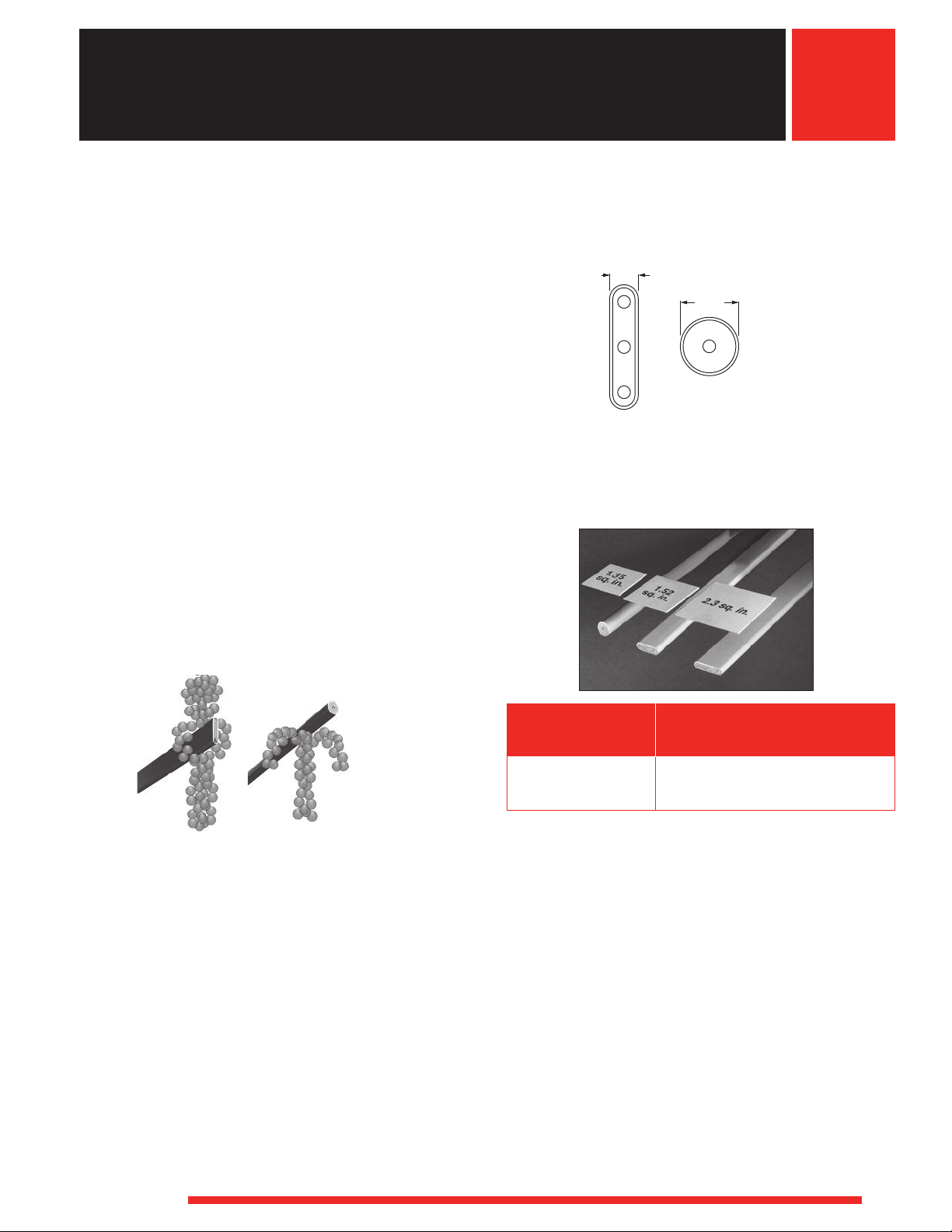
Comparative Widths
Watt Density and Surface Area Advantages
The surface area per linear inch of a 1 in. FIREBAR is
70 percent greater than the 0.430 in. (11 mm) diameter
round tubular element. The5⁄8 in. FIREBAR is nearly
10 percent greater.
2. Normal to the Flow
The element’s width (thickness) of both 1 inch and
5
⁄8 inch FIREBAR elements is just 0.235 in. (5.9 mm).
Compared to a 0.430 in. (11 mm) round tubular
element, this relative thinness further reduces drag
on liquids or gases flowing past the heater.
3. Buoyancy Force
The FIREBAR element’s boundary layer, or vertical side,
is greater than virtually all round tubular elements. This
is 1.010 and 0.650 in. (25.6 and 16.5 mm) for the one
inch and5⁄8 in. FIREBARs respectively, compared to a
0.430 in. (11 mm) diameter on a round tubular
element. The FIREBAR element’s increased height,
relative to flow, increases the buoyancy force in
viscous liquids. This buoyancy force can be as much as
10 times greater depending on the FIREBAR element
and liquid used.
WATLOW
®
Surface Area Per
Linear inch (cm)
Element Type in
1 in. FIREBAR 2.30 in
5
⁄8 in. FIREBAR 1.52 in
0.430 in. Round 1.35 in
2
2
2
2
(cm2)
(5.84 cm2)
(3.86 cm2)
(3.43 cm2)
Flat vs. Round Geometry Comparisons
The unique flat surface geometry of the FIREBAR
element offers more versatility in solving heater problems
than the conventional round tubular element. The
following comparisons show how the FIREBAR element
consistently outperforms round tubular heaters.
FIREBAR elements can:
• Reduce coking and fluid degrading
• Increase heater power within application space
parameters
• Provide superior heat transfer in clamp-on applications
resulting from greater surface area contact
• Lower watt density
Reducing watt density or sheath temperature extends life.
The FIREBAR element allows you to do either, without
sacrificing equipment performance … as is proven by the
accompanying Heater Oil Test, Air Flow and Watt Density
vs. Sheath Temperature graphs.
95
Page 6
Tubular Heaters
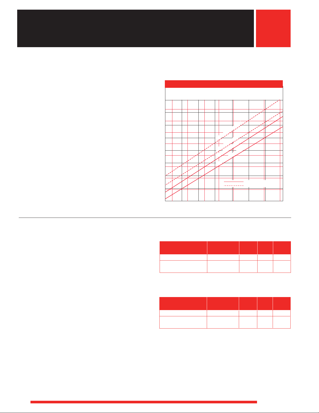
Oil Temperature —°F
Sheath Temperature —°F
700
650
600
550
500
450
400
350
300
150 200 250 300 350 400 450 500
1 Inch FIREBAR Heater
0.430 Inch Round Tubular
350
325
300
275
250
225
200
175
150
75 100 125 150 175 200 225 250
Sheath Temperature —°C
Oil Temperature —°C
40 W/
i
n
2
(
6.2 W/
cm
2
)
30 W
/i
n
2
(4.7 W
/
cm
2
)
40 W/i
n
2
(6.2
W/
cm
2
)
30 W
/i
n
2
(
4.7 W/cm
2
)
FIREBAR Single/Double-Ended Heater
Technical Data
The FIREBAR Heater Oil Test graph compares sheath
temperatures of 40 W/in2(6.7 W/cm2) flat and round
tubular elements. The FIREBAR element consistently
operates at a lower sheath temperature than the round
tubular element, even when light oils are tested at
different temperatures. This reduces the chance that
coking and fluid degradation will occur.
In fact, the FIREBAR element’s sheath temperature
at 40 W/in2(6.7 W/cm2) is lower than a 30 W/in
(4.6 W/cm2) round tubular element.
2
s
FIREBAR Heater Oil Test
Heater Size and Power
The Heater Size Comparison chart shows, at the same
wattage and watt density, the FIREBAR element is
38 percent shorter than a 0.430 in. (11 mm) round
tubular element. The FIREBAR element requires less
space in application and equipment designs.
The Heater Power Comparison chart demonstrates equal
watt density, element length and increased total wattage
for the FIREBAR element. The power in the FIREBAR
element is 70 percent greater.
96
Heater Size Comparison
Heated Length
Element in. (mm) Wattage W/in2(W/cm2)
1 in. FIREBAR Element 197⁄8 (504.8) 1000 23 (3.6)
0.430 in. Round
Tubular Element 321⁄4 (819.0) 1000 23 (3.6)
Heater Power Comparison
Heated Length
Element in. (mm) Wattage W/in2(W/cm2)
1 in. FIREBAR Element 321⁄4 (819.0) 1700 23 (3.6)
0.430 in. Round
Tubular Element 321⁄4 (819.0) 1000 23 (3.6)
WATLOW
®
Page 7

Tubular Heaters
45
40
35
30
25
20
15
10
5
200 400 600 800 1000
Platen Temperature —°F
Watt Density —W/in
2
200°F
4
00
°F
6
00°F
8
00
°F
1
000°F
Sheath Temperature
Subtract 20% of Indicated Watt
Density for 2 Element FIREBAR
7
6
5
4
3
2
1
100 200 300 400 500
Platen Temperature —°C
1
00°C
2
00°C
30
0
°C
400°C
500°
C
600
Sheath Temperature
Subtract 20% of Indicated Watt
Density for 2 Element FIREBAR
1400
1200
1000
800
600
400
200
10 20 30 40 50
Watt Density—W/in
2
Sheath Temperature —°F
60
0
1600
1800
1 2 3 4
Watt Density—W/cm
2
9
800
700
600
500
400
300
200
Sheath Temperature —°C
0
900
1000
100
5 6 7 8
Air
SAE 3
0
C
o
ok
i
ng O
i
l
Wate
r
FIREBAR Single/Double-Ended Heater
Technical Data (Continued)
Clamp-On Applications
Direct immersion in the liquid may not always be
practical. In these instances the FIREBAR element can
be clamped to a tank wall. Heat from the FIREBAR is
conducted to the tank wall and into the media.
Platen Heating (˚F)
Allowable Watt Densities of FIREBARs in Clamp-on-Application
s
FIREBAR elements are also economical platen heaters.
The Platen Heating graph shows FIREBAR’s large, flat
surface area allows it to operate at twice the watt
density of round tubular elements … without sacrificing
heater life.
Clamps should be placed approximately 6 in. (150 mm)
apart and torqued down with 60 in-lbs (6.8 Newton
meters).
Platen Heating (˚C)
Allowable Watt Densities of FIREBARs in Clamp-on-Application
Watt Density vs. Sheath Temperature
The Watt Density vs. Sheath Temperature graph features
sheath temperature curves for commonly heated
substances. A FIREBAR element’s watt density will result
in the sheath temperature shown at the intersecting point
of its vertical watt density line and substance curve.
WATLOW
®
Watt Density vs. Sheath Temperature
97
Page 8

Tubular Heaters
1800
1600
1400
1200
1000
800
600
400
200
5 10 15 20 25 30 35 40 45 50 55 60
Watt Density —W/in
2
Sheath Temperature —°F
Max. Recommended Sheath Temperature
1 FPS
4 FPS
9 FPS
16 FPS
20 FPS
900
800
700
600
500
400
300
200
100
1 2 3 4 5 6 7 8 9 10
Watt Density—W/cm
2
Sheath Temperature—°C
0.3 MPS
1.2 MPS
2.7 MPS
4.9 MPS
6.1 MPS
1000
Max. Recommended
Sheath Temperature
FIREBAR Single/Double-Ended Heater
Technical Data (Continued)
Air Heating
The Air Flow/Watt Density/Sheath Temperature graph
shows the relationship between air flow, watt density and
sheath temperature. Keep in mind that lower sheath
temperature yields longer heater life.
To use the Air Flow graph,determine the air flow in feet
per second (or meters per second). Then follow the curve
to find the recommended sheath temperature and
watt density.
Air Flow/Watt Density/Sheath Temperature (°F)
Air Flow
s
Air Flow Normal to Sheath Geometry
Air Flow/Watt Density/Sheath Temperature (°C)
Air Flow
Moisture Resistant Seals
A lavacone seal is provided to prevent moisture and
contaminants from entering the heater. Upon request,
optional silicone rubber (RTV) and epoxy resin seals may
be ordered.
Silicone Rubber (RTV) Seal
Silicone rubber RTV seals are1⁄8 in. (3.2 mm) moisture
barriers surrounding the terminal pins at the end of the
sheath. Silicone rubber is effective to 392°F (200°C).
Epoxy Resin Seal
Epoxy resin seals are1⁄8 in. (3.2 mm) moisture barriers
surrounding the terminal pins at the end of the sheath.
Epoxy resin is effective to 194°F (90°C) or 356°F (180°C),
and recommended for water heating applications.
98
Application Hints
• Choose a FIREBAR heating element instead of an
assembly, when the application requires lower
wattages or smaller system packages.
• Keep terminations clean, dry and tight.
• Extend the heated section completely into the media
being heated at all times to maximize heat transfer and
heater life.
• Do not locate the end of the heated length within a
bend, unless the radius is 3 in. (76 mm) or larger.
• Ensure termination temperatures do not exceed 392°F
(200°C) or the maximum temperature rating of the end
seal, whichever is lower.
WATLOW
®
Page 9

Tubular Heaters
FIREBAR Single/Double-Ended Heater
All FIREBAR heaters are available with a variety of
s
termination options. Contact your Watlow representative
Technical Data (Continued)
Terminations
Code 1 in. FIREBAR
Number* Termination Phase Wiring Dual-Ended S. End/FINBAR Dual-Ended Single-Ended
Al
Sil-A-Blend™ 200°C lead wire
Sil-A-Blend™ 200°C lead wire
A2
A3
Sil-A-Blend™ 200°C lead wire
A4
Sil-A-Blend™ 200°C lead wire
B1 TGGT 250°C lead wire 1 Parallel Yes Yes Yes Yes
B2 TGGT 250°C lead wire 1 Series Yes No Yes No
B3 TGGT 250°C lead wire 3 Delta Yes No No No
B4 TGGT 250°C lead wire 3 Wye Yes Yes No No
C11⁄4 in. quick connect (spade) 1 Parallel Yes Yes Yes Yes
C21⁄4 in. quick connect (spade) 1 Series Yes No No No
D1 Screw lug (plate) terminal 1 Parallel Yes Yes Yes Yes
D2 Screw lug (plate) terminal 1 Series Yes No No No
D3 Screw lug (plate) terminal 3 Delta Yes No No No
E1 #10-32 stud terminal 1 Parallel Yes Yes Yes Yes
E2 #10-32 stud terminal 1 Series Yes No No No
E3 #10-32 stud terminal 3 Delta Yes No No No
Termination Code Number Legend*
A = Silicone rubber insulation (Sil-A-Blend™) with fiberglass oversleeves
Rated to 392°F (200°C)
B = High-temperature TGGT insulation with fiberglass oversleeves
Rated to 480°F (250°C)
C = Nickel-plated steel quick connect
1 Parallel Yes Yes Yes Yes
1 Series Yes No Yes No
3 Delta Yes No No No
3 Wye Yes Yes No No
for availability.
5
/8in. FIREBAR
D = Nickel-plated steel screw lug with ceramic insulator and plated
steel screw
E = #10-32 nickel-plated steel threaded stud with plated steel nuts and
washers
Electrical Configuration
1 = 1-phase parallel, 2 = 1-phase series, 3 = 3-phase delta,
4 = 3-phase wye
Double-End FIREBAR
Flexible Lead Wire
A, B
➀
Screw Lug (Plate)
D1
Screw Lug (Plate)
D3
Threaded Stud
E2
• Double-End 1 in. FIREBAR
• Single-End 1 in. FIREBAR
• FINBAR
Quick Connect (Spade)
C1
• Double-End 1 in. FIREBAR
Quick Connect (Spade)
C2
• Double-End 1 in. FIREBAR
Single-End FIREBAR
Flexible Lead Wire
A, B
• Single-End 1 in. FIREBAR
• Double-End
• Single-End5⁄8 in. FIREBAR
• FINBAR
WATLOW
5
⁄8 in. FIREBAR
®
➀
• Double-End 1 &
5
⁄8 in. FIREBAR
Screw Lug (Plate)
D2
• Double-End 1 in. FIREBAR
Quick Connect (Spade)
C3
• Single-End 1 FIREBAR
• FINBAR
5
• Double-End
• Single-End5⁄8 in. FIREBAR
⁄8 in. FIREBAR
• Double-End 1 in. FIREBAR
3-phase delta
wiring example
Threaded Stud
E1
5
• Double-End 1 &
⁄8 in. FIREBAR
Screw Lug (Plate)
D4
• Single-End 1 in. FIREBAR
• FINBAR
• Double-End
• Single-End5⁄8 in. FIREBAR
5
⁄8 in. FIREBAR
• Double-End 1 in. FIREBAR
Threaded Stud
E3
• Double-End 1 in. FIREBAR
3-phase delta
wiring example
➀
Flexible lead wires are 12 in. (305 mm)
long unless otherwise specified.
Threaded Stud
E4
• Single-End 1 in. FIREBAR
• FINBAR
➀
Flexible lead wires are 12 in. (305 mm)
long unless otherwise specified.
99
Page 10

Tubular Heaters
0.235 in.
(5.9 mm)
1 in.
(25 mm)
A
1 in.
(25 mm)
Min.
No-Heat
R
1 in.
(25 mm)
0.235 in.
(5.9 mm)
No-Heat
R
A
1 in. (25 mm) Min.
2.5 in. (64 mm)
Min.
No-Heat
R
A
B
1 in.
(25 mm)
Min.
R
A
B
No-Heat
3.5 in. (89 mm)
Min.
0.235 in.
(5.9 mm)
1 in.
(25 mm)
A
1 in. (25 mm) Min.
R
B
No-Heat
1 in. (25 mm)
Min.
1 in. (25 mm)
0.235
in.
(5.9 mm)
A
2 in. (51 mm) Min.
No-Heat
B
R
1 in. (25 mm)
Min.
FIREBAR Single/Double-Ended Heaters
Bending
Major and Minor Axis Bending Parameters
The following illustrations detail the recommended major
and minor axis bend parameters for FIREBAR
elements. These illustrations show the relationship
between the type of bend and the location of heat and
no-heat sections. See the next two pages for the
15 common bend formations.
Note: Watlow does not recommend field bending
FIREBAR elements. If the element must be bent in the
field, please contact your Watlow representative for
assistance.
180° Minor Axis Heated Bend
90° Minor Axis Heated Bend
180° Major Axis Heated Bend
90° Major Axis Heated Bend
90° Minor Axis Un-Heated Bend
100
180° Major Axis Bends
FIREBAR Size Radius
in. (mm) in. (mm) Arc Length
5
1
⁄8 (15.9)
5
1
⁄8 (15.9) 1 (25.0) 3.900
5
⁄8 (15.9) 11⁄4 (32.0) 4.620
1
5
1
⁄8 (15.9) 11⁄2 (38.0) 5.600
1 (25.0) 1 (25.0) 4.335
1 (25.0) 11⁄4 (32.0) 5.121
1 (25.0) 11⁄2 (38.0) 5.906
3
1
⁄4 (19.0) 3.125
WATLOW
®
Page 11

Tubular Heaters
A
H
R
1
R
1
R
2
H
A
C
L
A
C
L
H
R
1
R
2
H
R
1
A
<°
(Angle)
F
R
2
R
1
A
H
R
2
K
A
H
R
1
R
2
K
A
H
R
1
H
A
R
1
R
1
H
R
2
A
<°
(Angle)
F
R
1
R
2
H
K
A
H
R
1
R
2
K
A
A
H
R
1
R
1
R
2
R
1
H
A
L
R
3
K
A
R
1
R
2
R
1
H
L
R
3
K
A
R
1
R
1
R
2
L
H
FIREBAR Single/Double-Ended Heaters
Bend Formations
FIREBAR elements can be formed into spirals,
compounds, multi-axis and multi-plane configurations
from 15 common bends. Custom bending with
tighter tolerances can be made to meet specific
application needs.
Formation is limited by bending parameters specified in
the illustrations of major and minor axis bends on the
previous page. On these illustrations, please note the
no-heat end location.
Minor Axis Major Axis Major AxisMinor Axis
Figure 1B
Figure 1A
Figure 3A
The no-heat end junction must be located a minimum of
1 in. (25 mm) from any bend. If these parameters are not
followed, the heater may fail prematurely.
Illustrated below are the common bends that can be
ordered for all FIREBAR heating elements.
To order a common bend, specify the figure number
and critical dimensions.
Note: The alpha characters and symbols are used to
designate specific dimensions within each illustration.
Figure 2A
Figure 2B
Figure 4BFigure 4AFigure 3B
Figure 5A
Figure 7A
WATLOW
Figure 5B
R
1
R
2
R
1
L
A
®
H
Figure 7B
Figure 6A
Figure 8A
Figure 6B
Figure 8B
101
Page 12

Tubular Heaters
L
R
1
R
2
H
A
K
B
R
1
R
1
R
3
R
4
R
2
X Hairpins
<°
(Angle)
R
1
L
B
H
K
R
1
A
R
2
H
K
R
1
R
2
L
B
A
L
R
1
R
2
A
H
R
1
R
1
R
2
X Hairpins
R
3
K
L
A
H
R
1
R
1
R
1
R
2
R
2
X Hairpins
R
3
K
L
R
1
R
2
A
H
R
1
R
1
R
2
X Hairpins
A
H
L
R
1
R
1
R
1
R
2
R
2
X Hairpins
L
H
A
K
B
R
1
R
1
R
1
R
3
R
4
R
2
R
2
X Hairpins
R
1
K
H
A
G
K
A
R
1
H
L
R
1
R
2
A
H
L
K
R
1
R
1
R
2
FIREBAR Single/Double-Ended Heaters
Bend Formation (Continued)
Minor Axis Major Axis Major AxisMinor Axis
Figure 9A
Figure 9B
Bend Figure
11B
Not Available
On Major Axis
Figure 10A
Bend Figure
10B
Not Available
On Major Axis
Figure 12BFigure 12AFigure 11A
Figure 15A
102
Figure 13BFigure 13A
Figure 15B
Figure 14A Figure 14B
WATLOW
®
Page 13

Tubular Heaters
1
5
/8 in. -
10 UNC
0.753 in.
(19 mm)
0.940 in.
(23.9 mm)
0.187 in.
(4.8 mm)
2.25 in.
(57 mm)
0.125 in. Max.
No Threads
9
/16 in.
(14.3 mm)
Wall
Washer
Nut
Gasket
2.625 in.
(66.7 mm)
(2) 0.25 in.
(6 mm) Dia.
1.5 in.
(38 mm)
3.25 in.
(83 mm)
1.75 in.
(45 mm)
4.875 in.
(123.8 mm)
1.75 in.
(45 mm)
3 in.
(76 mm)
5.5 in.
(140 mm)
(2) 0.25 in.
(6 mm) Dia.
(2) 0.25 in.
(6 mm) Dia.
1.75 in.
(45 mm)
1.125 in.
(28.6 mm)
1.75 in.
(45 mm)
FIREBAR Single/Double-Ended Heaters
Mounting Brackets
Steel brackets provide element mounting in
non-pressurized applications. In air heating applications,
an 18-gauge aluminized steel bracket is press fitted to
the element. A1⁄4 in. (6 mm) thick steel bracket is brazed
or welded liquid-tight to the element for liquid heating.
Upon request, stainless steel brackets can be provided.
Special sizes also available.
The bracket is located1⁄2 in. (13 mm) from the sheath’s
end,1⁄16 in. (1.6 mm) if welded. Available on5⁄8 in.
(15.9 mm) FIREBAR as made-to-order only.
To order, specify mounting bracket as well as type,
location, material and size.
Type 1
Water-Tight Double-Leg Threaded Fitting
5
A threaded 1
flange on the heater sheath provides rigid, leak-proof
mounting through tank walls. This fitting allows both legs
of the heater to pass through the same opening. A
gasket, plated steel washer and hex nut are included.
The threaded end of the bulkhead is mounted flush with
the sheath’s end, unless otherwise specified. Available
on 1 inch FIREBAR only (brazed only, available).
To order, specify water-tight double-leg threaded
fitting.
⁄8 in.-10 UNC stainless steel fitting with
Type 2
Type 3
WATLOW
®
Surface Finish
Bright Annealing
Bright annealing is a process that produces a smooth,
metallic finish. It is a special annealed finish created in a
non-oxidizing atmosphere. This finish is popular in the
pharmaceutical and foodservice/beverage markets.
To order, specify bright annealing.
Passivation
During manufacturing, particles of iron or tool steel may
be embedded in the stainless steel or alloy sheath. If not
removed, these particles may corrode and produce rust
spots. For critical sheath applications, passivation will
remove free iron from the sheath.
To order, specify passivation.
103
Page 14

Tubular Heaters
15
/16 in. (23.8 mm)
3
/4 in.
(19 mm)
3
/16 in.
(4.8 mm)
Wall
Washer
Nut
Gasket
11/4 in.
(32 mm)
Extended Capabilities For
FIREBAR Single/Double-Ended Heaters
XTE
E
APABILITY
C
NDED
Internal Thermocouples
To provide protection against element over-temperature
conditions, 1 in. (25 mm) double-ended FIREBAR
elements can be ordered with ASTM Type K
thermocouples. This is accomplished by eliminating the
center resistance coil and embedding the thermocouple
junction inside the sheath. Thus, thermocouples are
available only on two resistance coil, 1 in. (25 mm)
FIREBAR elements.
To order, specify:
• Type K thermocouple
• Distance the junction is to be located from the
element’s end
• Lead length
Thermocouple Types
Recommended
®
Temp. Range
°F (°C)
0 to 2000
(-20 to 1100)
ASTM
Type
K Chromel
➀ Type K thermocouples are rated 32 to 2282°F (0 to 1250°C).
Watlow does not recommend exceeding the temperature range
shown on this chart.
Conductor
Positive
®
(Non-magnetic)
Characteristics
Negative
Alumel
(Magnetic)
Options for5⁄8-Inch FIREBAR
• Electropolished finish
• Custom formations
• Cordset
• Termination overmolds (silicone or neoprene)
• Terminal enclosures (general purpose, moisture
resistant, moisture/explosion resistant and explosion
resistant)
• Internal thermocouple (dual end only, single or dual coil
• Custom wattage tolerance (±5%)
Options for One-Inch FIREBAR
• Electropolished finish
• Bulkhead, single leg
• Custom formations
• Cordset
• Termination overmolds (silicone or neoprene)
• Terminal enclosures (general purpose, moisture
resistant, moisture/explosion resistant and explosion
resistant)
• Internal thermocouple (dual end only, single or dual coil
• Custom wattage tolerance (±5%)
Mounting Brackets
Threaded Bulkheads
A threaded stainless steel bushing with flange on the
heater sheath provides rigid, leak-proof mounting
through tank walls. A gasket, plated steel washer and
hex nut are included (brazed only, available).
To order, specify threaded bulkheads.
Illustration for5⁄8-inch FIREBAR
Illustration for 1-inch FIREBAR
1
1
(32 mm)
/4 in.
Heater Size Thread
in. (mm) Size
5
⁄8 (15.9)
1 (25.0)
7
⁄8-14 UNF-2A
3
⁄4-16 UNF-2A
104
WATLOW
®
Page 15

Tubular Heaters
No-Heat
Sheath Length
A
Heated Length
B
No-Heat
Lavacone Seal
Straight Length Annealed Incoloy
®
Sheath Permits
Factory Bending to Customer Requirements
12 in. (305 mm)
Standard Leads
6 Per Element
½ in.
(13 mm)
RAPID SHIP
FIREBAR Single/Double-Ended Heaters
One-Inch, Double-Ended FIREBAR
FIREBAR Sheath Heated Est. Net
Description A Dimension B Dimension Watts Code Number Wt.
Applications: Asphalt, Paraffin (Solid), Bunker Oil, Clamp-On
2
6 W/in
®
Incoloy
(1 W/cm
Applications: Griddles, Fuel Oil, Clamp-On
10 W/in
Incoloy
(1.6 W/cm
Applications: Clamp-On, Medium Weight Oils, Liquid Paraffin, Low-Temperature Ovens 400°F (205°C)
15 W/in2➀ 29 (736) 19 (482) 670 FBN2910WE 1.1 (0.5)
Incoloy
(2.3 W/cm
Applications: Radiant, Platens, Dies, Low-Temperature Ovens 300°F (150°C)
20 W/in
Incoloy
(3.1 W/cm
Applications: Degreasing Solutions, Heat Transfer Oils
23 W/in
Incoloy
(3.6 W/cm
WATLOW
2
) 51 (1295) 41 (1041) 530 FBN511WD FBN5110WD 1.9 (0.9)
2
®
®
2
®
2
®
in. (mm) in. (mm) 120VAC 240VAC 480VAC lbs (kg)
35 (889) 25 (635) 310 FBN351WD 1.3 (0.6)
41 (1041) 31 (787) 410 FBN411WD 1.5 (0.7)
62 (1574) 52 (1320) 650 FBN621WD FBN6210WD 2.3 (1.1)
72 (1828) 62 (1574) 800 FBN721WD FBN7210WD 2.6 (1.2)
93 (2362) 83 (2108) 1,060 FBN931WD FBN9310WD 3.4 (1.6)
114 (2895) 104 (2641) 1,350 FBN1141WD FBN11410WD 4.2 (1.9)
25 (635) 22 (558) 500 FBN251WL 0.9 (0.4)
35 (889) 32 (812) 750 FBN351WL FBN3510WL 1.3 (0.6)
2
) 47 (1193) 43 (1092) 1,000 FBN471WL FBN4710WL 1.7 (0.8)
69 (1752) 65 (1651) 1,500 FBN691WL FBN6910WL 2.5 (1.2)
90 (2286) 86 (2184) 2,000 FBN901WL FBN9010WL 3.3 (1.5)
34 (863) 24 (609) 830 FBN3410WE 1.3 (0.6)
2
) 39 (990) 29 (736) 1,000 FBN3910WE 1.4 (0.7)
48 (1219) 38 (965) 1,330 FBN4810WE FBN4811WE 1.8 (0.9)
58 (1473) 48 (1219) 1,670 FBN5810WE FBN5811WE 2.1 (1.0)
68 (1727) 58 (1473) 2,000 FBN6810WE FBN6811WE 2.5 (1.2)
87 (2209) 77 (1955) 2,670 FBN8710WE FBN8711WE 3.2 (1.5)
106 (2692) 96 (2438) 3,330 FBN10610WE FBN10611WE 3.9 (1.8)
15 (381) 11 (279) 500 FBN151WM 0.6 (0.3)
20 (508) 16 (406) 750 FBN201WM 0.8 (0.4)
2
) 26 (660) 22 (558) 1,000 FBN261WM FBN2610WM 1.0 (0.5)
36 (914) 32 (812) 1,500 FBN361WM FBN3610WM 1.3 (0.6)
48 (1219) 43 (1092) 2,000 FBN481WM FBN4810WM 1.8 (0.9)
70 (1778) 65 (1651) 3,000 FBN7010WM FBN7011WM 2.6 (1.2)
91 (2311) 85 (2159) 4,000 FBN9110WM FBN9111WM 3.3 (1.5)
35 (889) 25 (635) 1,250 FBN351WT FBN3510WT 1.3 (0.6)
41 (1041) 31 (787) 1,625 FBN411WT FBN4110WT 1.5 (0.7)
2
) 51 (1295) 41 (1041) 2,125 FBN511WT FBN5110WT FBN5111WT 1.9 (0.9)
62 (1574) 52 (1320) 2,625 FBN621WT FBN6210WT FBN6211WT 2.3 (1.1)
72 (1828) 62 (1574) 3,200 FBN721WT FBN7210WT FBN7211WT 2.6 (1.2)
93 (2362) 83 (2108) 4,250 FBN931WT FBN9310WT FBN9311WT 3.4 (1.6)
114 (2895) 104 (2641) 5,400 FBN1141WT FBN11410WT FBN11411WT 4.2 (1.9)
• Available on all elements unless otherwise noted
CONTINUED
• Same day shipment up to 15 pieces
®
➀ Delivery, 10 working days
Truck Shipment only
105
Page 16

Tubular Heaters
No-Heat
Sheath Length
A
Heated Length
B
No-Heat
Lavacone Seal
Straight Length Annealed Incoloy
®
Sheath Permits
Factory Bending to Customer Requirements
12 in. (305 mm)
Standard Leads
6 Per Element
½ in.
(13 mm)
RAPID SHIP
FIREBAR Single/Double-Ended Heaters
One-Inch, Double-Ended FIREBAR (Continued)
FIREBAR Sheath Heated Est. Net
Description A Dimension B Dimension Watts Code Number Wt.
in. (mm) in. (mm) 120VAC 240VAC 480VAC lbs (kg)
Applications: Cooking Oils, Mild Caustic Solution, Ethylene Glycol (100%)
2
30 W/in
®
Incoloy
(4.7 W/cm
Applications: Process Water, Ethylene Glycol (50%)
2
40 W/in
®
Incoloy
(6.2 W/cm
2
45 W/in
®
Incoloy
(7 W/cm
2
) 39 (990) 29 (736) 3000 FBN3910WP 1.4 (0.7)
Applications: Clean and Potable Water
2
80 W/in
®
Incoloy
(12.4 W/cm
2
90 W/in
®
Incoloy
(14 W/cm
2
16 (406) 10 (254) 750 FBN161WH 0.6 (0.3)
20 (508) 14 (355) 1000 FBN201WH 0.8 (0.4)
2
) 27 (685) 21 (533) 1500 FBN271WH FBN2710WH 1.0 (0.5)
34 (863) 28 (711) 2000 FBN341WH FBN3410WH 1.3 (0.6)
50 (1270) 43 (1092) 3000 FBN5010WH FBN5011WH 1.8 (0.9)
64 (1625) 57 (1447) 4000 FBN6410WH FBN6411WH 2.4 (1.1)
80 (2032) 72 (1828) 5000 FBN8010WH FBN8011WH 2.9 (1.4)
25 (635) 22 (558) 2000 FBN2510WK 0.9 (0.4)
35 (889) 32 (812) 3000 FBN3510WK FBN3511WK 1.3 (0.6)
2
) 47 (1193) 43 (1092) 4000 FBN4710WK FBN4711WK 1.7 (0.8)
69 (1752) 65 (1651) 6000 FBN6910WK FBN6911WK 2.5 (1.2)
90 (2286) 86 (2184) 8000 FBN9010WK FBN9011WK 3.3 (1.5)
29 (736) 19 (482) 2000 FBN2910WP 1.1 (0.5)
34 (863) 24 (609) 2500 FBN3410WP 1.3 (0.6)
48 (1219) 38 (965) 4000 FBN4810WP FBN4811WP 1.8 (0.9)
58 (1473) 48 (1219) 5000 FBN5810WP FBN5811WP 2.1 (1.0)
68 (1727) 58 (1473) 6000 FBN6810WP FBN6811WP 2.5 (1.2)
87 (2209) 77 (1955) 8000 FBN8710WP FBN8711WP 3.2 (1.5)
106 (2692) 96 (2438) 10,000 FBN10610WP FBN10611WP 3.9 (1.8)
15 (381) 11 (279) 2000 FBN1510WJ 0.6 (0.3)
20 (508) 16 (406) 3000 FBN2010WJ 0.8 (0.4)
2
) 26 (660) 22 (558) 4000 FBN2610WJ FBN2611WJ 1.0 (0.5)
36 (914) 32 (812) 6000 FBN3610WJ FBN3611WJ 1.3 (0.6)
48 (1219) 43 (1092) 8000 FBN4810WJ FBN4811WJ 1.8 (0.9)
70 (1778) 65 (1651) 12,000 FBN7011WJ 2.6 (1.2)
91 (2311) 85 (2159) 16,000 FBN9111WJ 3.3 (1.5)
35 (889) 25 (635) 5000 FBN351WG FBN3510WG FBN3511WG 1.3 (0.6)
41 (1041) 31 (787) 6500 FBN411WG
➀
FBN4110WG FBN4111WG 1.5 (0.7)
) 51 (1295) 41 (1041) 8500 FBN5110WG FBN5111WG 1.9 (0.9)
62 (1574) 52 (1320) 10,500 FBN6210WG FBN6211WG 2.3 (1.1)
72 (1828) 62 (1574) 12,750 FBN7210WG FBN7211WG 2.6 (1.2)
93 (2362) 83 (2108) 17,000 FBN931WG 3.4 (1.6)
114 (2895) 104 (2641) 21,500 FBN11411WG 3.4 (1.6)
• Available on all elements unless otherwise noted
• Same day shipment up to 15 pieces
➀ Delivery, 10 working days
Truck Shipment only
106
WATLOW
®
Page 17

Tubular Heaters
No-Heat
Sheath Length
A
Heated Length
B
No-Heat
Lavacone Seal
Straight Length Annealed Incoloy
®
Sheath Permits
Factory Bending to Customer Requirements
12 in. (305 mm)
Standard Leads
4 Per Element
1
/2 in.
(13 mm)
RAPID SHIP
FIREBAR Single/Double-Ended Heaters
5
⁄8-Inch Double-Ended FIREBAR
FIREBAR Sheath Heated Est. Net
Description A Dimension B Dimension Watts Code Number Wt.
in. (mm) in. (mm) 120VAC 240VAC 480VAC lbs (kg)
Applications: Degreasing Fluids, Heat Transfer Oils
23 W/in2➀ 19 (483) 11 (279) 375 FAN191WT 0.5 (0.3)
®
Incoloy
(3.6 W/cm2) 26 (660) 18 (457) 625 FAN261WT FAN2610WT 0.6 (0.3)
Applications: Clean and Potable Water
2
90 W/in
®
Incoloy
(14 W/cm2) 22 (559) 14 (356) 2000 FAN221WG FAN2210WG➀ FAN2211WG 0.5 (0.3)
22 (559) 14 (356) 500 FAN221WT FAN2210WT 0.5 (0.3)
30 (762) 22 (559) 750 FAN301WT FAN3010WT 0.7 (0.4)
37 (940) 29 (737) 1000 FAN371WT FAN3710WT 0.9 (0.5)
44 (1118) 36 (914) 1250 FAN441WT FAN4410WT 1.0 (0.5)
51 (1295) 43 (1092) 1500 FAN511WT FAN5110WT 1.2 (0.6)
15 (381) 7 (178) 1000 FAN151WG➀ FAN1510WG 0.4 (0.2)
19 (483) 11 (279) 1500 FAN191WG FAN1910WG➀ FAN1911WG 0.5 (0.3)
26 (660) 18 (457) 2500 FAN261WG FAN2610WG➀ FAN2611WG 0.6 (0.3)
30 (762) 22 (559) 3000 FAN301WG➀ FAN3010WG➀ FAN3011WG 0.7 (0.4)
37 (940) 29 (737) 4000 FAN3710WG➀ FAN3711WG 0.9 (0.5)
44 (1118) 36 (914) 5000 FAN4410WG➀ FAN4411WG 1.0 (0.5)
51 (1295) 43 (1092) 6000 FAN5110WG➀ FAN5111WG 1.2 (0.6)
• Available on all elements unless otherwise noted
• Same day shipment up to 15 pieces
➀ Delivery, 10 working days
WATLOW
®
107
Page 18

Tubular Heaters
1
1
/4 in.
(32 mm)
No-Heat
Sheath Length
A
Heated Length
B
1 in. (25 mm)
No-Heat
12 in. (305 mm) Standard Leads
2 per Element
1
in. (25 mm)
1
/4 in.
(6 mm)
5
/16 in.
(7.9 mm)
1
/2 in.
(13 mm)
0.235 in.
(5.9 mm)
Lavacone
Seal
RAPID SHIP
FIREBAR Single/Double-Ended Heaters
One-Inch, Single-Ended FIREBAR
FIREBAR Sheath Heated Est. Net
Description A Dimension B Dimension Watts Code Number Wt.
in. (mm) in. (mm) 120VAC 240VAC lbs (kg)
Applications: Radiant, Platens, Dies, Low-Temperature Ovens 300°F (150°C)
2
20 W/in
304 SS 101⁄4 (260.0) 71⁄2 (203.0) 375 FSP101WM 0.4 (0.2)
(3.1 W/cm2) 121⁄4 (311.0) 10 (254.0) 450 FSP121WM 0.5 (0.3)
Applications: Process Water, Ethylene Glycol (50%)
2
40 W/in
304 SS 101⁄4 (260.0) 71⁄2 (203.0) 750 FSP101WK 0.4 (0.2)
(6.2 W/cm2) 121⁄4 (311.0) 10 (254.0) 900 FSP121WK FSP1210WK 0.5 (0.3)
83⁄4 (222.0) 61⁄2 (165.0) 300 FSP91WM 0.4 (0.2)
131⁄2 (343.0) 111⁄4 (286.0) 500 FSP141WM 0.5 (0.3)
161⁄8 (408.6) 137⁄8 (352.4) 650 FSP161WM FSP1610WM 0.6 (0.3)
173⁄4 (451.0) 151⁄2 (393.0) 725 FSP181WM FSP1810WM 0.7 (0.4)
191⁄4 (489.0) 17 (431.0) 800 FSP191WM FSP1910WM 0.7 (0.4)
22 (558.0) 193⁄4 (502.0) 900 FSP221WM FSP2210WM 0.8 (0.4)
233⁄4 (603.0) 211⁄2 (546.0) 1,000 FSP241WM FSP2410WM 0.9 (0.4)
25 (635.0) 223⁄4 (578.0) 1,050 FSP251WM FSP2510WM 0.9 (0.4)
285⁄8 (727.1) 263⁄8 (670.0) 1,250 FSP291WM FSP2910WM 1.1 (0.5)
315⁄8 (803.3) 293⁄8 (746.1) 1,350 FSP321WM FSP3210WM 1.2 (0.6)
341⁄8 (866.8) 317⁄8 (809.6) 1,500 FSP3410WM 1.3 (0.6)
367⁄8 (936.6) 345⁄8 (879.5) 1,600 FSP3710WM 1.4 (0.7)
405⁄8 (1031.9) 383⁄8 (974.7) 1,800 FSP4110WM 1.5 (0.7)
461⁄4 (1175.0) 44 (1117.0) 2,000 FSP4610WM 1.7 (0.8)
83⁄4 (222.0) 61⁄2 (165.0) 600 FSP91WK 0.4 (0.2)
131⁄2 (343.0) 111⁄4 (286.0) 1,000 FSP131WK FSP1310WK 0.5 (0.3)
161⁄4 (413.0) 137⁄8 (352.4) 1,300 FSP161WK FSP1610WK 0.6 (0.3)
173⁄4 (451.0) 151⁄2 (393.0) 1,450 FSP181WK FSP1810WK 0.7 (0.4)
191⁄4 (489.0) 17 (431.0) 1,600 FSP1910WK 0.7 (0.4)
22 (558.0) 193⁄4 (502.0) 1,800 FSP2210WK 0.8 (0.4)
233⁄4 (603.0) 211⁄2 (546.0) 2,000 FSP2410WK 0.9 (0.4)
25 (635.0) 223⁄4 (578.0) 2,100 FSP2510WK 0.9 (0.4)
285⁄8 (727.1) 263⁄8 (669.9) 2,500 FSP2910WK 1.1 (0.5)
315⁄8 (803.2) 293⁄8 (746.1) 2,700 FSP3210WK 1.2 (0.6)
341⁄8 (866.8) 317⁄8 (809.6) 3,000 FSP3410WK 1.3 (0.6)
367⁄8 (936.6) 345⁄8 (879.5) 3,200 FSP3710WK 1.4 (0.7)
405⁄8 (1031.9) 383⁄8 (974.7) 3,600 FSP4110WK 1.5 (0.7)
461⁄4 (1175.0) 44 (1117.0) 4,000 FSP4610WK 1.7 (0.8)
• Available on all elements unless otherwise noted
• Same day shipment up to 15 pieces
108
WATLOW
®
Page 19

Tubular Heaters
1
1
/4 in.
(32 mm)
No-Heat
Sheath Length
A
Heated Length
B
1 in.
(25 mm)
Min. No-Heat
1
/2 in.
(13 mm)
5
/8
in.
(15.9 mm)
0.235 in.
(5.9 mm)
1
/4 in.
(6 mm)
5
/16 in.
(7.9 mm)
12 in. (305 mm)
Standard Leads
2 Per Element
Lavacone
Seal
RAPID SHIP
FIREBAR Single/Double-Ended Heaters
5
⁄8-Inch Single-Ended FIREBAR
FIREBAR Sheath Heated Est. Net
Description A Dimension B Dimension Watts Code Number Weight
in. (mm) in. (mm) 120VAC 240VAC lbs (kg)
Applications: Radiant, Platens, Dies, Low-Temperature Ovens 300°F (150°C)
2
20 W/in
®
Incoloy
(3.1 W/cm2) 191⁄2 (495) 16 (406) 500 FSA201WM FSA2010WM 0.5 (0.3)
111⁄2 (292) 8 (203) 250 FSA121WM 0.3 (0.2)
151⁄2 (394) 12 (304) 375 FSA161WM FSA1610WM 0.4 (0.2)
28 (711) 24 (609) 750 FSA281WM FSA2810WM 0.6 (0.3)
36 (914) 32 (812) 1,000 FSA361WM FSA3610WM 0.8 (0.4)
52 (1321) 48 (1219) 1,500 FSA521WM FSA5210WM 1.2 (0.6)
• Available on all elements unless otherwise noted
• Same day shipment up to 15 pieces
WATLOW
®
109
 Loading...