

Page 1
SPECIFICATION SHEET
EZ-ZONE® ST
EZ-ZONE® ST Integrated
Control Loop Makes
Solving the Thermal
Requirements of Your
System Easy
The EZ-ZONE® ST integrated solid state controller from
Watlow® offers a complete thermal system control solution
in a single package. Features include a PID temperature
controller connected to a high-amperage solid state relay
with the option of adding a properly sized heat sink, an
over- and under-temperature limit, a power shut-down
contactor, digital communications and a remote user
interface in one complete and professionally engineered
product.
Because the system is modular and scalable, a user only pays
for what is needed. Stacking the EZ-ZONE ST integrated
controller into multiple configurations enables flexibility to
standardize the product platform to solve a wide range of
application needs.
This integrated controller also includes 200KA short circuit
current rating (SCCR) tested up to 480VAC to minimize
damage in the event of a short circuit when used with
required fusing.
Features and Benefits
Back panel or DIN-rail mount
• Provides several mounting options
Compact package
• Reduces panel size
Touch-safe package
• Complies to IP2X increasing user safety
±0.1 percent temperature accuracy
• Provides efficient and accurate temperature control
200KA SCCR with proper fusing
• Minimizes damage in the event of a short circuit
Agency approvals: UL®, CSA, CE, RoHS, W.E.E.E.
• Meets applications requiring agency approvals
Three-year warranty
• Ensures Watlow’s reliability and product support
Off-the-shelf designed system solution
• Improves system reliability and termination reduction
• Reduces installation cost
• Eliminates incompatibility headaches often encountered
with using many different components and brands
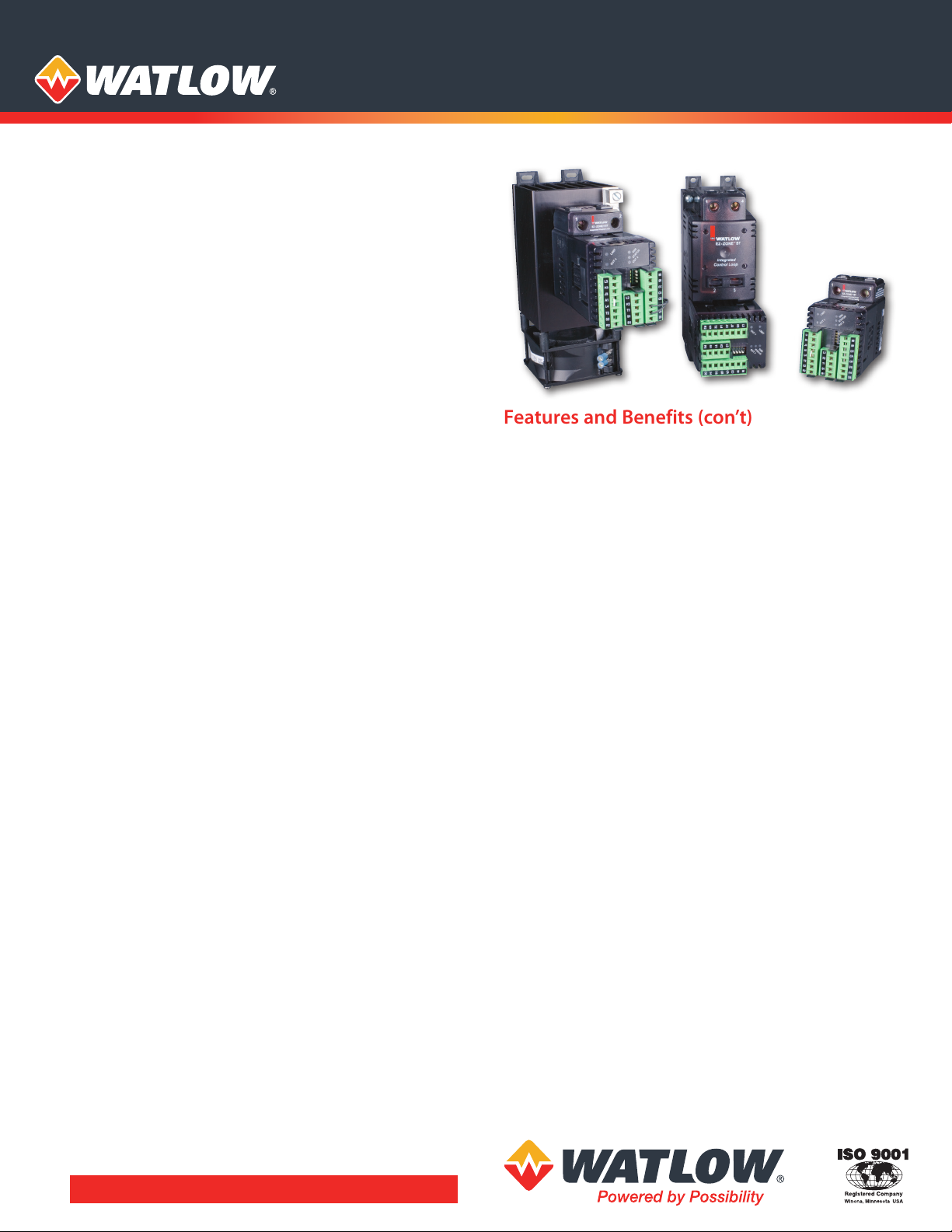
EZ-ZONE ST
75 ampere configuration
EZ-ZONE ST
40 ampere full configuration
with mechanical contactor
EZ-ZONE ST
configuration with only
the controller and SSR
Features and Benefits (con’t)
Profile capability
• Includes ramp and soak with four files and 40 total steps
Ability to communicate with programmable logic controller
(PLC), personal computer (PC) or operator interface (OIT)
• Optional EIA 485 Modbus® RTU
• RUI/communications gateway with optional EIA 232/485
Modbus® RTU, EtherNet IP™/TCP Modbus®, DeviceNet™ or
PROFIBUS DP
Solid state relay output
• Allows faster cycling, more precise control, increased heater
life and energy efficiency
• Ability to handle up to 75 amperes
• Uses either zero-cross or phase angle control modes for
flexibility to control resistive loads such as nichrome,
tungsten or quartz lamps
• Utilizes phase angle control mode to prevent load failure or
blowing fuses for tungsten or quartz loads
PID temperature control
• Allows single input/dual output
• Allows standard PID or adaptive TRU-TUNE®+ tuning
algorithms for demanding controllability requirements
Optional temperature limit
• Increases safety in
Optional definite purpose mechanical contactor
• Enables circuit safety shut down driven by limit control or
PID alarm output signal
Optional current monitoring feature
• Detects heater current flow and alarm indication of failed
solid state relay (SSR) or heater zone
Optional SSR heat sink
• Sized and engineered for specific applications
• Factory supplied heat sink is UL® listed
System diagnostics
• Provides continuous self-monitoring alerts when there is
any system trouble to reduce maintenance and service costs
PC Software—EZ-ZONE Configurator
• Wizard style configuration of controller settings
• On-line or off-line recipe editing
over- and under-temperature
condition
Multiple U.S. and international patents pending.
Page 2

Specifications
Line Voltage/Power
• 100 to 240VAC, +10/-15%; (85-264VAC), 50/60Hz, ±5%
• 24VAC/VDC, +10/-15%; 50/60Hz, ±5%
• 12VA max. power consumption without mechanical contactor
in system
• 50VA max. power consumption with mechanical contactor
used in system, 140VA if using external contactor
• Data retention upon power failure via nonvolatile memory
Environment
• 0 to 158°F (-18 to 70°C) operating temperature
• -40 to 185°F (-40 to 85°C) storage temperature
• 0 to 90% RH, non-condensing
Accuracy
• Calibration accuracy and sensor conformity: ±0.1% of span,
±1°C @ the calibrated ambient temperature and rated line
voltage
• Types R, S, B: 0.2%
• Type T below -50°C: 0.2%
• Calibration ambient temperature @ 77°F ±5°F (25°C ±3°C)
• Accuracy span: 1000°F (540°C) min.
• Temperature stability: ±0.1°F/°F (±0.1°C/°C) rise in ambient max.
Agency Approvals
• UL®, CSA, CE (zero cross models only), RoHS, W.E.E.E.
• Limit version features FM approval
Controller
• Microprocessor based user-selectable control modes
• PID module: single universal input, 2 outputs
• Limit module: single universal input, 2 outputs
• Two total additional digital input/outputs shared between PID
and limit functions
• Control sampling rates: input = 10Hz, outputs = 10Hz
• Isolated EIA 485 Modbus® RTU serial communications
Wiring Termination—Touch Safe Terminals
• Input, power and controller output terminals touch safe
removable 12 to 22 AWG
• Power load terminals 6 to 12 AWG
• Tightening torque: 30 in.-lbs
Universal Input
• Thermocouple, grounded or ungrounded sensors
• >20MΩ input impedance
• Max. of 20Ω source resistance
• RTD 2- or 3-wire, platinum, 100Ω and 1000Ω @ 0°C calibration to
DIN curve (0.00385Ω/Ω/°C)
• Process, 0-20mA @ 100Ω, or 0-10VDC @ 20kΩ input impedance;
scalable, 0-50mV
• Inverse scaling
Digital Input
• Update rate: 1Hz
• Dry contact or dc voltage
DC voltage
• Max. input: 36V at 3mA
• Min. high state: 3V at 0.25mA
• Max. low state: 2V
Dry contact
• Max. short circuit: 13mA
• Min. open resistance: 500Ω
• Max. closed resistance: 100Ω
Current Measurement
• Accuracy: typical ±1A, max. error ±3A
• Accuracy and operating range: 0 to 75A
Digital Output
• Update rate: 1Hz
• Output voltage: 24V, current limit 10mA
Allowable Operating Range
Type J: 32 to 1500°F or 0 to 815°C
Type K: -328 to 2500°F or -200 to 1370°C
Type T: -328 to 750°F or -200 to 400°C
Type N: 32 to 2372°F or 0 to 1300°C
Type E: -328 to 1470°F or -200 to 800°C
Type C: 32 to 4200°F or 0 to 2315°C
Type D: 32 to 4200°F or 0 to 2315°C
Type F: 32 to 2543°F or 0 to 1395°C
Type R: 32 to 3200°F or 0 to 1760°C
Type S: 32 to 3200°F or 0 to 1760°C
Type B: 32 to 3300°F or 0 to 1816°C
RTD (DIN): -328 to 1472°F or -200 to 800°C
Process: -1999 to 9999 units
Output Hardware
• User selectable for heat/cool as on-off, P, PI, PD, PID, or alarm
action. Not valid for limit controls
• Electromechanical relay. Form A, rated 2A
• SSR drive: 20-28VDC low side open collector switch
• SSR, Form A, 0.5A @ 24VAC min., 264VAC max., opto-isolated,
without contact suppression
• Electromechanical relay, Form A, rated 5A, auxiliary output on
PID module, output 2
• Electromechanical relay, Form C, rated 5A, auxiliary output on
limit module, output 3
Specifications for Basic Remote User Interface EZKB (RUI)
Operator Interface
• Dual 4 digit, 7 segment LED displays
• Forward, backward, up and down keys plus a customer
programmable function key - EZ key
• Typical display update rate: 1Hz
• Agency approved to IP65/NEMA 4X
• Standard bus (ships with all units). Options:
EIA 232/485
DeviceNet™, PROFIBUS DP
Line Voltage/Power
• 100 to 240VAC, +10/-15%; (85-264VAC) 50/60Hz, ±5%
• 24VAC/VDC, +10/-15%; 50/60Hz, ±5%
Modbus® RTU, EtherNet/IP™/TCP Modbus® or
Specifications for Mechanical Contactor
• Insulation class: UL® Class B 266°F (130°C)
• Min. load of 100 watts
Contact Ratings
Full Load Number Line Locked Resistive Amp Max. Horsepower
Amperes of Poles Voltage Rotor Amps Rating Voltage Single-Phase
40 2 240/277 240 50 120 2
480 200 50 240 3
600 160 50
• Duty cycle: continuous
Page 3

EZ-ZONE ST Solid State Relay with Heat Sink Specifications
Amperage/Temperature Derating Curves
Ez Zone ST
Temperature and SSR Amperage Performance Curve
Watlow 25, 40 and 75 Ampere Solid State Relays
80
70
60
50
40
30
Amperes (Full On)
20
10
0
0
5
10
40A at 50°C
25A at 50°C
35
15
20 25
Degree °C (Heatsink Inlet Temperature)
30
40
45
50
75A at 70°C
60
55
65
70
25A
40A
75A
All Versions
Current output (50°C) 25 Amps 40 Amps 75 Amps
One-cycle surge current 600Apk 850Apk 1350Apk
Max. I2t for fusing 1500A2s 3000A2s 7560A2s
Thermo resistance 0.35°C/W 0.2°C/W 0.14°C/W
Base plate temperature (max.) 116°C 115°C 112°C
Forward voltage drop 1.3Vpk 1.3Vpk 1.3Vpk
Min. holding current 150mA 150mA 250mA
Frequency 47 to 63Hz 47 to 63Hz 47 to 63Hz
Time Proportioned Models
Off-state leakage 1mA
Max. off-state dv/dt 500V/µsec
120/240VAC
Output voltage range
Over voltage rating 600Vpk
Input voltage range 0 to 28VDC
75
277/600VAC
Output voltage range
Over voltage range 1200Vpk
Input voltage range 0 to 28VDC
Phase Angle Models
Off-state leakage 6mA
Max. off-state dv/dt 200V/µsec
120/240VAC
Output voltage range
Over voltage rating 600Vpk
Input voltage range 2.7 to 10VDC
277/600VAC
Output voltage range
Over voltage range 1200Vpk
Input voltage range 2.8 to 10VDC
24 to 280VAC
48 to 660VAC
100 to 240VAC
260 to 600VAC
RUI (EZKB) Utilized as a Communication Gateway Device
OIT
EIA 232/485 Modbus® RTU
EtherNet/IP™/TCP Modbus
The RUI (EZKB) can be used as a
communication gateway to connect
any EZ-ZONE controller with standard
bus to other system components using
different communication protocols such
as EIA 232/485 Modbus® RTU, EtherNet
IP™/Modbus® TCP, DeviceNet™ or
PROFIBUS DP.
Watlow Standard Bus Free
communication protocol in all
EZ-ZONE controllers
PLC
DeviceNet™
PROFIBUS DP
PC
®
RUI (EZKB)
Up to 16
of any
EZ-ZONE
controller
Page 4

EZ-ZONE ST with Definite Purpose Mechanical Contactor—Dimensional Drawing
40A
6.14 in. ref.
(156 mm)
25A heat sink (shown)
6.14 in. ref.
(156 mm)
40A heat sink same as 25A
for this dimension
1.65 in.
(41.9 mm)
1.38 in.
(35 mm)
7 in.
(177.8 mm)
1.43 in.
(36.2 mm)
7.43 in.
(188.6 mm)
2.5 in.
(63.5 mm)
25A (shown)
3.88 in.
(98.6 mm)
40A
4.98 in.
(126.5 mm)
1.16 in.
(29.5 mm)
Note: EZ-ZONE ST needs to be mounted
vertically (as shown) to meet amp/ambient
performance curve.
EZ-ZONE ST with 25 or 40A Heat Sink, without Definite Purpose Mechanical Contactor—
Dimensional Drawing
2.03 in.
(51.6 mm)
1.43 in.
(36.2 mm)
7.43 in.
7 in.
(177.8 mm)
0.68 in.
(17.4 mm)
3.43 in.
(87 mm)
(63.5 mm)
25A (shown)
3.88 in.
(98.6 mm)
(188.6 mm)
2.5 in.
6.14 in. ref.
(156 mm)
25A (shown)
6.14 in. ref.
(156 mm)
40A same as 25A
for this dimension
4.98 in.
(126.5 mm)
1.38 in.
(35 mm)
1.16 in.
(29.5 mm)
1.65 in.
(41.9 mm)
Note: EZ-ZONE ST needs to be mounted
vertically (as shown) to meet amp/ambient
performance curve.
EZ-ZONE ST with 75A Heat Sink, without Definite Purpose Mechanical Contactor—
Dimensional Drawing
2.03 in.
(51.6 mm)
4.98 in.
8.47 in.
(215.1 mm)
3.51 in.
(89.2 mm)
1.38 in.
(35 mm)
1.57 in.
(39.9 mm)
Note: EZ-ZONE ST needs
to be mounted vertically
(as shown) to meet amp/
ambient performance
curve.
5.45 in.
(138.5 mm)
3.43 in.
(87 mm)
1.11 in.
(28.1 mm)
1.81 in.
(46 mm)
1.89 in.
(48 mm)
3.15 in.
(80 mm)
7.76 in.
(197.1 mm)
120 and 240VAC
fan (shown)
7.26 in.
(184.4 mm)
24VDC fan
(126.5 mm)
Page 5

Communications
Selecting the right communications ordering option for the EZ-ZONE ST:
Correct Another RUI, EZ-ZONE Third Party Device Silver Series
Ordering EZ-ZONE Configurator, (PLC, PC, Operator Interface
Option Letter Connecting To Product SpecView Touch Panel, etc.) Terminal
Option A* Yes
Option M** Yes - Via Modbus®
Option A* Yes Yes
Option M** Yes Yes - Via Modbus®
Yes - Via Modbus®
Yes - Via Modbus®
Ordering Information
Part Number
① ②
ST
③
Integrated
PID Controller
⑦
④
Integrated
Limit
Controller
⑤ ⑥
Mech. Cont. &
Power Supply
Options
⑦
Communications
⑧
SSR
⑨
Heat Sink/
DIN-Rail
Mtg. Brkt.
⑩
Firmware
⑪ ⑫
Customization
*A = Standard
bus used to
connect to
Watlow PC
software, RUI,
other EZ-ZONEs
**M =Modbus®
RTU (needed to
communicate
to third-party
devices) and
standard bus.
User selectable
③
Total of 2 Digital Current
Output 1* Output 2 I/O Points Measurement
K =
SSR drive 0.5A SSR No No
B =
SSR drive 0.5A SSR Yes No
P =
SSR drive 0.5A SSR No Yes
E =
SSR drive 0.5A SSR Yes Yes
H =
SSR drive 5A mechanical relay No No
D =
SSR drive 5A mechanical relay Yes No
J =
SSR drive 5A mechanical relay No Yes
C =
SSR drive 5A mechanical relay Yes Yes
Integrated PID Controller
* Output 1 is dedicated to providing the command signal to the
internal SSR.
Note: If 75A heat sink is selected below, then 1 digital I/O will be
factory set and fixed as the SSR over-temperature digital input.
④
Integrated Limit Controller
A = None
L = Limit control module with output 3, 5A Form C mechanical
relay; with output 4, 2A Form A mechanical relay
B = No limit control module but access to coil connection on
mechanical contactor
⑤ ⑥
Mechanical Contactor and Power Supply Options
AH=
No contactor and universal high voltage power supply
100-240VAC/VDC
AL =
No contactor and universal low voltage power supply
24- 28VAC/VDC
B1 =
Single pole, 40A Watlow contactor, 24VAC power supply
B2 = Single pole, 40A Watlow contactor, 110/120VAC power supply
B3 = Single pole, 40A Watlow contactor, 208/240VAC power supply
F1 =
Dual pole, 40A Watlow contactor, 24VAC power supply
F2 =
Dual pole, 40A Watlow contactor, 110/120VAC power supply
F3 =
Dual pole, 40A Watlow contactor, 208/240VAC power supply
⑦
A =
Standard bus used to connect to Watlow PC software, RUI,
Communications
other EZ-ZONEs
M =
485 Modbus® RTU (needed to communicate to third-party
devices) and standard bus. User selectable
⑧
SSR
B = Zero cross 10A (24 to 240VAC output)
C =
Zero cross 25A (24 to 240VAC output)
D =
Zero cross 40A (24 to 240VAC output
E =
Zero cross 50A (24 to 240VAC output
K =
Zero cross 75A (24 to 240VAC output)
F =
Zero cross 90A (24 to 240VAC output)
G =
Zero cross 25A (48 to 600VAC output)
H =
Zero cross 40A (48 to 600VAC output)
L =
Zero cross 75A (48 to 600VAC output)
J =
Zero cross 90A (48 to 600VAC output)
M =
Phase angle 25A (100 to 240VAC output)
N =
Phase angle 40A (100 to 240VAC output)
P =
Phase angle 75A (100 to 240VAC output)
R =
Phase angle 25A (260 to 600VAC output)
S =
Phase angle 40A (260 to 600VAC output)
T =
Phase angle 75A (260 to 600VAC output)
Note: EZ-ZONE ST phase angle is designed to work with tungsten
or quartz loads. The EZ-ZONE ST should not be used with globars,
molybdenum, graphite or transformer loads.
⑨
Heat Sinks/DIN-Rail Mounting Bracket
A = None
B =
25A
C =
40A
D =
75A 24VDC fan cooled
E =
75A 115VAC fan cooled
F =
75A 240VAC fan cooled
Note: If heat sink option D, E or F is selected you must also order
integrated PID controller options B, E, D or C. 75A heat sink option
includes SSR over-temperature thermostat shut-down feature.
⑩
A =
Standard Watlow
P =
Profile ramp and soak (40 total steps, 1 to 4 profiles total)
S =
Custom
⑫
Customization (logo, parameters, hardware, firmware)
⑪
AA =
Standard
XX =
Letters to be determined, contact factory
Note:
Maximum rating of final configured product is determined by
Firmware
the lowest component rating of either the mechanical contactor,
solid-state relay or heat sink. Maximum UL® rating for product is 75A.
Page 6

Remote User Interface (RUI)—
(52.07 mm)
2.05 in.
(52.07 mm)
2.05 in.
(1.52 mm)
Dimensional Drawings
Front View
2.05 in.
(52.07 mm)
2.05 in.
(52.07 mm)
Short Case Version
0.66 in.
(16.79 mm)
0.06 in.
Ordering Information
Part Number
①②③
EZK
④
B =
⑤
④
Remote
User
Interface
Basic 1/16 DIN
⑤
Power Supply
Voltage
for RUI
Comm.
Gateway
Options
-
Remote User Interface (RUI)
Power Supply Voltage for RUI
L = Low voltage 24-28VAC/VDC
H = Universal high voltage 100-240VAC/VDC
⑥
Communication Gateway Options*
(Standard Bus Always Included)
A = None
2 = EIA232/485 Modbus® RTU
3 = EtherNet/IP™/Modbus® TCP
5 = DeviceNet™
6 = PROFIBUS DP
* Options 2 through 6 require the long case dimensions
⑧
⑦
AA =
None
12 =
Custom options, contact factory
⑫
⑪
AA =
None
XX =
Class 1, Div. 2 (only available with communication options
Custom RUI
Custom Options
2, 3, 5 and 6)
Watlow®, EZ-ZONE® and TRU-TUNE® are registered trademarks of Watlow Electric
Manufacturing Company.
UL® is a registered trademark of Underwriter’s Laboratories Inc.
Modbus® is a registered trademark of Schneider Automation Incorporated.
DeviceNet™ and EtherNet/IP™ are trademarks of Open DeviceNet Vendors Association.
⑦ ⑧
⑥
Custom
RUI
-
⑨ ⑩
Future
Options
AA
2.28 in.
(57.94 mm)
⑪ ⑫
Custom
Options
Long Case Version
0.62 in.
2.10 in.
(53.34 mm)
(15.82 mm)
0.40 in.
(10.16 mm)
0.06 in.
(1.52 mm)
1.20 in.
(30.49 mm)
Compatible Accessories
The EZ-ZONE configurator software
is available FREE as a download at
www.watlow.com. Looking for an
easy-to-use method for configuring all parameter settings via PC?
Simply download the EZ-ZONE
configurator software and
connect via the standard bus
communication protocol.
The communication protocol
is included with every
EZ-ZONE ST.
SpecView from Watlow is designed
for industrial users and includes
features such as data logging,
trending and support for bar code
readers and touch screens. Errors are
reduced for any process by creating
application-specific screens.
The software provides a historical
replay option, easy-to-use recipe
features and remote access options,
including LAN, internet and modem.
4.00 in.
(101.57 mm)
Watlow also offers a line
of Operator Interface Terminals
(OIT). Refer to the Watlow
Silver Series OIT product
specification sheet on the
web at www.watlow.com
Powered by Possibility
To be automatically connected to the nearest
North American Technical Sales Oce:
1-800-WATLOW2 • www.watlow.co
inquiry@watlow.com
©2016 Watlow Electric Manufacturing Company all rights reserved.
International Technical Sales Offices:
China +86 21 3532 8532
France +33 1 41 32 79 70
Germany +49 7253 9400 0
India +91 40 6661 2700
Italy +39 02 4588841
Japan +81 3 3518 6630
Korea +82 2 2169 2600
Mexico +52 442 256 2200
Singapore +65 6773 9488
Spain +34 91 675 1292
Taiwan +886 7 288 5168
UK +44 115 964 0777
WIN-EZST-0916
 Loading...