

Page 1
ISO 9001
EZ-ZONE® RME (Expansion) Module
User’s Guide
Expansion Module
TOTAL
CUSTOMER
SATISFACTION
3 Year Warranty
Registered Company
Winona, Minnesota USA
1241 Bundy Boulevard., Winona, Minnesota USA 55987
Phone: +1 (507) 454-5300, Fax: +1 (507) 452-4507 http://www.watlow.com
0600-0073-0000 Rev. D Made in the U.S.A.
December 2013
Page 2
Safety Information
We use note, caution and warning symbols throughout this book to
draw your attention to important operational and safety information.
A “NOTE” marks a short message to alert you to an important
detail.
A “CAUTION” safety alert appears with information that is
important for protecting your equipment and performance. Be
especially careful to read and follow all cautions that apply to
your application.
A “WARNING” safety alert appears with information that is
important for protecting you, others and equipment from damage. Pay very close attention to all warnings that apply to your
application.
The safety alert symbol, (an exclamation point in a triangle)
precedes a general CAUTION or WARNING statement.
The electrical hazard symbol, (a lightning bolt in a triangle)
precedes an electric shock hazard CAUTION or WARNING
safety statement. Further explanations follow:
Symbol Explanation
CAUTION – Warning or Hazard
that needs further explanation
than label on unit can provide.
Consult User's Guide for further
information.
ESD Sensitive product, use proper
grounding and handling techniques when installing or servicing product.
Unit protected by double/reinforced insulation for shock hazard
prevention.
Do not throw in trash, use proper
recycling techniques or consult
manufacturer for proper disposal.
Enclosure made of Poly carbonate
material. Use proper recycling
techniques or consult manufacturer for proper disposal.
Unit is compliant with European
Union directives. See Declaration
of Conformity for further details
on Directives and Standards used
for Compliance.
Unit has been reviewed and approved by Factory Mutual as a
Temperature Limit Device per FM
Class 3545 standard. See: www.
fmglobal.com
Unit has been reviewed and approved by CSA International for
use as Temperature IndicatingRegulating Equipment per CSA
C22.2 No. 24. See: www.csa-inter-
national.org
Warranty
The EZ-ZONE® RME (Expansion) module is manufactured by ISO
9001-registered processes and is backed by a three-year warranty to
the first purchaser for use, providing that the units have not been
misapplied. Since Watlow has no control over their use, and sometimes misuse, we cannot guarantee against failure. Watlows' obligations hereunder, at Watlows' option, are limited to replacement,
repair or refund of purchase price, and parts which upon examination prove to be defective within the warranty period specified. This
warranty does not apply to damage resulting from transportation,
alteration, misuse or abuse. The purchaser must use Watlow parts
to maintain all listed ratings.
Technical Assistance
If you encounter a problem with your Watlow RME module, review
your configuration information to verify that your selections are
consistent with your application: inputs, outputs, alarms, limits, etc.
If the problem persists, you can get technical assistance from your
local Watlow representative (see back cover), by e-mailing your questions to wintechsupport@watlow.com or by dialing +1 (507) 494-5656
between 7 a.m. and 5 p.m., Central Standard Time (CST). Ask for
for an Applications Engineer. Please have the following information
available when calling:
• Complete model number
• All configuration information
• User's Guide
• Factory Page
Unit can be powered with either
alternating current (ac) voltage or
direct current (dc) voltage.
Unit is a Listed device per Underwriters Laboratories®. It has
been evaluated to United States
and Canadian requirements for
Process Control Equipment. UL
61010 and CSA C22.2 No. 61010.
File E185611 QUYX, QUYX7.
See: www.ul.com
Unit is a Listed device per Underwriters Laboratories®. It has
been evaluated to United States
and Canadian requirements for
Hazardous Locations Class 1
Division II Groups A, B, C and
D. ANSI/ISA 12.12.01-2007. File
E184390 QUZW, QUZW7. See:
www.ul.com
Return Material Authorization
1. Call Watlow Customer Service, (507) 454-5300, for a Return
Material Authorization number before returning any item for
repair. If you do not know why the product failed, contact an
Application Engineer or Product Manager. All Return Material
Authorization’s require:
• Ship-to address
• Bill-to address
• Contact name
• Phone number
• Method of return shipment
• Your P.O. number
• Detailed description of the problem
• Any special instructions
• Name and phone number of person returning the product.
2. Prior approval and a Return Material Authorization number
from the Customer Service Department is required when
Page 3

returning any product for credit, repair or evaluation. Make
sure the RMA number is on the outside of the carton and on all
paperwork returned. Ship on a Freight Prepaid basis.
3. After we receive your return, we will examine it and try to
verify the reason for returning it.
4. In cases of manufacturing defect, we will enter a repair order,
replacement order or issue credit for material returned. In cases
of customer misuse, we will provide repair costs and request a
purchase order to proceed with the repair work.
5. To return products that are not defective, goods must be in new
condition, in the original boxes and they must be returned within 120 days of receipt. A 20 percent restocking charge is applied
for all returned RM modules and accessories.
6. If the unit cannot be repaired, you will receive a letter of explanation and be given the option to have the unit returned to you
at your expense or to have us scrap the unit.
7. Watlow reserves the right to charge for no trouble found (NTF)
returns.
This EZ-ZONE RME User's Guide is copyrighted by
Watlow Winona, Inc., © December 2013 with all rights
reserved.
EZ-ZONE RM is covered by U.S. Patent No. 6,005,577
and Patents Pending
Page 4

TC
Table of Contents
Chapter 1: Overview .....................................3
A Conceptual View of the RM System .......................... 6
Chapter 2: Install and Wire ................................11
Wiring .................................................. 16
Conventions Used in the Menu Pages ......................... 29
Chapter 3: Operations Pages ..............................30
Digital Input / Output Menu ................................. 31
Action Menu .............................................31
Alarm Menu ............................................. 31
Current Menu ............................................32
Linearization Menu ........................................33
Compare Menu ........................................... 33
Timer Menu .............................................34
Counter Menu ............................................ 34
Logic Menu .............................................. 35
Math Menu ..............................................36
Special Output Function Menu ...............................37
Chapter 4: Setup Pages ..................................39
Digital Input / Output Menu ................................. 41
Action Menu .............................................42
Output Menu ............................................. 44
Alarm Menu ............................................. 47
Current Menu ............................................49
Linearization Menu ........................................50
Compare Menu ........................................... 52
Timer Menu .............................................54
Counter Menu ............................................ 57
Logic Menu .............................................. 59
Math Menu ..............................................68
Special Output Function Menu ...............................72
Variable Menu ............................................ 76
Global Menu .............................................76
Watlow EZ-ZONE® RM System • 1 • Table of Contents
Page 5

TC
Table of Contents (cont.)
Chapter 5: Factory Pages .................................77
Custom Setup Menu ....................................... 78
Security Setting Menu ..................................... 78
Security Setting Menu ..................................... 80
Diagnostics Menu ......................................... 80
Chapter 6: Features .....................................81
Saving and Restoring User Settings ........................... 82
Inputs ..................................................82
Outputs ................................................. 82
Alarms .................................................83
Using Password Security ..................................86
Software Configuration ..................................... 88
Function Block Descriptions ................................. 91
Chapter 7: Appendix ...................................112
Troubleshooting Alarms, Errors and Module Issues .............. 112
RME Specifications ....................................... 114
Index .................................................. 117
How to Reach Us ........................................121
Watlow EZ-ZONE® RM System • 2 • Table of Contents
Page 6

1
Chapter 1: Overview
Available EZ-ZONE RM System Literature and Resources
Document Title and Part Number Description
EZ-ZONE Rail Mount Access (RMA) User's Guide,
part number: 0600-0072-0000
EZ-ZONE Rail Mount Controller (RMC) User's
Guide, part number: 0600-0070-0000
EZ-ZONE Rail Mount High Density (RMH) User's
Guide, part number: 0600-0074-0000
EZ-ZONE Rail Mount Scanner (RMS) User's
Guide, part number: 0600-0071-0000
EZ-ZONE Rail Mount Limit (RML) User's Guide,
part number: 0600-0075-0000
EZ-ZONE Remote User Interface (RUI) User's
Guide, part number: 0600-0060-0000
EZ-ZONE RM Specification Sheet, part number:
WIN-EZRM-1113
Describes how to connect the RM system into an
industrial network, how to use data logging, module
backup and the real-time clock.
The RMC module is an advanced integrated controller capable of PID and limit control. This document
describes how to configure and program all loops of
control and communications.
This module extends the density of the standard RM
modules (number of control loops and I/O points).
The User Guide describes common usage, communications and the number I/O points available.
This module adds monitoring points to the RM system. This document describes common usage and
the various types of I/O available.
This module will protect against unwanted thermal
runaway and over temperature conditions. The User
Guide describes configuration, programming and
communications capabilities.
The RUI provides a visual LED display to the RM
configuration and setup menus. This document illustrates and describes connections and also describes
the Home Page for each RM module as viewed from
the RUI.
Describes RM hardware options, features, benefits
and technical specifications.
Watlow Support Tools DVD, part number: 06010001-0000
The DVD described above ships with the product and as stated contains all of the literature above as well
as much more. If the DVD is not available one can be acquired by contacting Watlow Customer Service at
1-507-454-5300.
As an alternative to the DVD, all of the user documentation described above can also be found on the Watlow website. Click on the following link to find your document of choice: http://www.watlow.com/literature/
index.cfm. Once there, simply type in the desired part number (or name) into the search box and download
free copies. Printed versions of all user documents can also be purchased here as well.
Contains all related user documents, tutorial videos,
application notes, utility tools, etc...
Your Comments are Appreciated
In an effort to continually improve our technical literature and ensure that we are providing information that
is useful to you, we would very much appreciate your comments and suggestions. Please send any comments
you may have to the following e-mail address: TechlitComments@watlow.com
Watlow EZ-ZONE® RME Module • 3 • Chapter 1 Overview
Page 7

Introduction
The EZ-ZONE® Rail Mount Expansion module
(RME) takes the pain out of adding I/O points to
your RM system architecture.
It just got a whole lot easier to solve the thermal
requirements of your system. The RME module is
provided in a space-saving, rail-mount package and
is highly scalable where you only pay for what you
need. For those applications that require the ability
to configure/monitor the control over a network, other communications protocols are also available (e.g.,
EtherNet/IP, DeviceNet, Modbus TCP and Profibus
DP) when used in conjunction with an RM Access
(RMA) module or when using a Remote User Interface/ Gateway (RUI/GTW).
Standard Features and Benefits
• Provides two mounting options (DIN rail, chassis
mount)
• Reduces wiring time and termination complexity
compared to connecting discrete products
• Reduces panel space and installation cost
Integrated power controller output
• Provides an optional dual Solid-State Relay (SSR)
outputs, which can drive up to 10 amps into resistive loads. Terminals for the ring lug connection is
optional
• Reduces component count and cost of ownership
• Saves panel space and simplifies wiring
Communication Capabilities
• Supports network connectivity to a PC or *PLC
• Provides a wide range of *protocol choices includ-
ing Modbus® RTU, EtherNet/IP™, Modbus® TC P,
DeviceNet™ and Profibus DP
* When used with the optional RMA or Remote User
Interface/Gateway
Additional control integration options
• Provides a sequencer function
• Includes programmable timer functions
• Includes programmable counter functions
• Allows for simple math and logic programming op-
tions
Integrated Thermal Loop Diagnostics
• Users can easily tell that the entire thermal sys-
tem is functioning properly
• Provides complete system diagnostics that are far
superior to simple discrete level diagnostics
• Helps prevent load loss or allow for maintenance
to be scheduled when more convenient.
• Provides notification of system problems to help
reduce maintenance and service costs
Off-the-Shelf Designed System Solution
• Improves system reliability with a factory inte-
Watlow EZ-ZONE® RME Module • 4 • Chapter 1 Overview
grated solution that minimizes inter-module connections and potential problems at screw termination points.
• Reduces installation cost
• Eliminates compatibility headaches often encountered with using many different components and
brands
RME Handles High Ambient Temperatures
• Operates in an unprecedented temperature range
of -18 to 65°C (0 to 149°F) for cabinets and panel
enclosures with elevated temperature levels
Optional Access Module Available
• Serves as a configuration station
• Provides communication capabilities between the
other modules and the PC or PLC
• Stores corresponding module parameter settings
for easy auto-configuration of other additional
modules or replacement modules
• Serves as a configuration station, which programs
initial module setup or automatic programming of
modules if swapping out after initial installation
• Provides a USB port for uploading and downloading configuration or data log files directly to a PC
• Saves time and increases reliability of parameter
setting
• Logs process data
Memory for Saving and Restoring User-Defined Parameter Default Settings
• Allows customers to save and restore their own
defined defaults for machine parameter settings
• Reduces service calls and downtime due to inadvertent end user parameter adjustments
RM Modules Allow for Greater Design Flex-
ibility
• Saves money because you do not pay for any more
than you need and don’t settle for any less functionality than you need
Synergistic Module Control (SMC)
• Allows outputs selected for control (heat/cool),
alarms or events to be located in any physical
module, regardless of which module is connected
to the input sensor
Split-Rail Control (SRC)
• Allows modules to be mounted together or mounted remotely from one another
• Shares control operation via Synergistic Module
Control (SMC) capability
• Allows individual modules to be mounted closer
to the physical input and output devices to which
they are wired
• Improves system reliability and lowers wiring
costs
Page 8

Agency Certifications: UL® listed, CE, RoHS,
W.E.E.E. SEMI F47-0200, Class 1 Div. 2 Rating
on Selected Models
• Assures prompt product acceptance
• Reduces panel builder's documentation and agency
costs
Removable Connectors
• Assures reliable wiring and reduces service calls
• Simplifies installation
• Provides a terminal option for accepting ring lug
connection
Three-Year Warranty
• Demonstrates Watlow’s reliability and product support
Watlow EZ-ZONE® RME Module • 5 • Chapter 1 Overview
Page 9

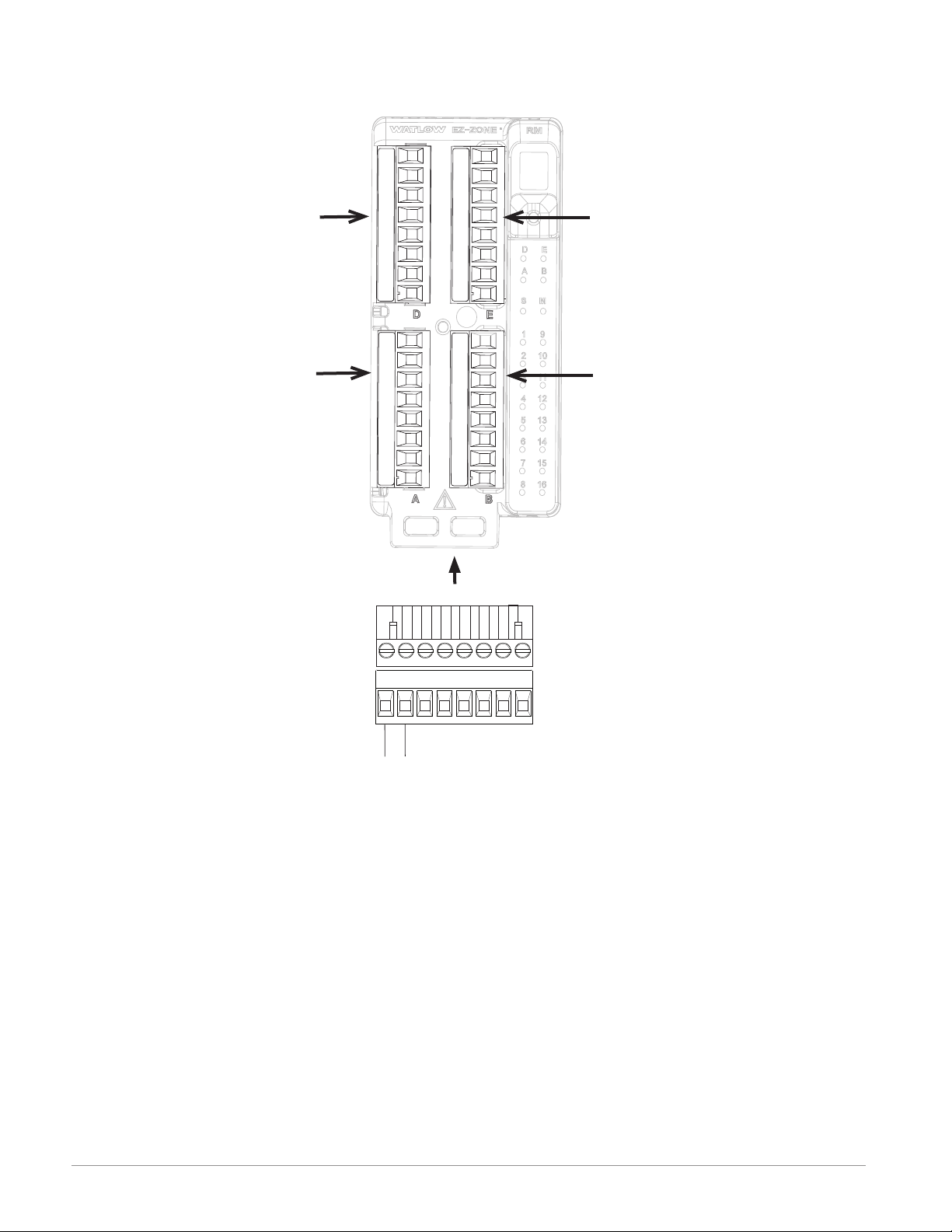
A Conceptual View of the RM System
The flexibility of the RM system software and hardware allows for a large range of configurations. Focusing on the RME module, acquiring a better understanding of its overall functionality and capabilities
while at the same time planning out how this module
can be used will deliver maximum effectiveness in
your application.
The RM system at a high level can have a total
of 17 modules installed, one of which can be an Access module and the others (16 maximum) can be any
combination of available RM modules. Each installed
RM module must have a unique Standard Bus address ranging from 1-9, A-F, H (10 -16). The Access
module will be delivered with a default Standard Bus
address of 17 (J). If not using the default zone address the user will need to define each zone address
via the button on the face of each module.
The RME can be considered an accessory RM
module in that by itself it has no PID control loops.
However, used in conjunction with an RM Controller (RMC) or RM High Density (RMH) module the
RME provides increased I/O capabilities. Outputs of
the RME can be used to drive output loads of various
kinds. For instance, an RME module could be placed
in a remote location (up to 200 feet away) from a PID
controller such as an RMC or RMH to drive a heater.
Some of the user selectable ordering options are
listed below:
1. Class 2 or SELV (Saftey Extra Low Voltage) equiv-
alent Power Supplies:
• 90-264 Vac to 24Vdc @ 31 watts
• 90-264 Vac to 24Vdc @ 60 watts
• 90-264 Vac to 24Vdc @ 91 watts
2. RM Expansion Module can provide:
• 1 to 24 Digital Inputs/Outputs (I/O)
• 4 to 12 Form A Mechanical Relays
• 2 to 4 Form A 10A Solid-State Relays
• 4 inputs for external Current Transformers
(CT)
When using this module, either as a stand-alone
module or used in conjunction with any other RM
module it is useful to remember that each process
needs to be thought out carefully and the controller’s
inputs, functions and outputs configured properly.
Note:
Zones can communicate with one another over the
backplane (local and split rail). Once the system is
configured and running changing zone addresses
without careful deliberation may cause disruption in
operation.
Outputs
Inputs
Functions
Process
Alarm
High
Silence
Alarms
* Output is driven from another
RM PID controller module
*PID
Heat
Power
Sequencing
Outputs
What is an Instance?
The RM system can have many I/O points, in some
cases, as described above, I/O can be placed in remote locations. For example, an RME module can
have 24 digital I/O where each would be numbered
from 1 to 24 and each would be considered a unique
instance. They are named Digital I/O 1, 2, 3, etc...
These instance numbers are then used when you
link inputs, functions and outputs within a module
or when linked to other modules. For example, when
configuring an RME output for heat the control loop
instance (1, 2, 3 or 4) and zone (1 to 16) to drive the
output must be defined.
Functions
Functions, in simple terms, use input signals (realworld or internal), to calculate a value and deliver an
output. A function may be as simple as configuring
the function of the digital output, e.g., alarm, heat,
etc..., or defining a set point for an alarm state to
turn on or off.
To set up a function, one of the first things that
must be considered is the function source and instance. For example, if the control is equipped with
Digital Inputs (source) and it was decided to use DI
9 (instance) it can then be associated with an Action
to reset an individual alarm or all alarms. The steps
below, walk through this configuration:
Setup Page (Digital I/O Menu)
1. Navigate to the Setup Page and then to the Digital
I/O menu.
2. Select the desired instance and set the direction to
input voltage or input dry contact.
Setup Page (Action Menu)
3. Navigate to the Setup Page and then the Action
menu.
4. Set the Action Function to Alarm
5. Select which alarm instance will be reset (0 equals
all)
6. Select the Source Function to Digital I/O
7. Select the Source Instance (step 2 above)
8. Select the Source Zone (0 equals the module being
configured).
9. Select the Active Level to execute the desired func-
tion.
When the selected digital input is active the alarm or
all alarms that are latched without a currently existing alarm condition will be reset. If a specific alarm
instance (1 - 8) is selected (step 5 above), it will be
Watlow EZ-ZONE® RME Module • 6 • Chapter 1 Overview
Page 10
that instance alone that will be reset.
Note:
Alarms will reset automatically when the condition
that caused the alarm goes back to a non-alarm state
if the alarm latching prompt is set to non-latching
(Setup Page, Alarm Menu).
Keep in mind that a function is a user-programmed
internal process that does not execute any action
outside of the controller. To have any affect outside
of the controller, an output must be configured to respond to a function.
Some functions have a hardware input for which
the source/s are preset and cannot be changed. As
an example, CT 1 source function comes not surprisingly, from the CT attached to it. Most functions can
accept more than one input and it would not be uncommon to see the output of one function (internal)
serve as an input to another, as would be the case
with a compare function. The source parameters for
the first input to a function are called Source Function A, Source Instance A and Source Zone A and the
second input, Source Function B, Source Instance B
and Source Zone B and so on.
Inputs
The inputs provide the information that any given
programmed function can act upon. This information
may come from an operator pushing a button, or as
part of a more complex function it may represent one
of ten inputs used for the Linearization function.
Each digital input reads whether a device is active
or inactive. An RME module can be equipped with up
to 24 digital inputs, where the RM system can have
many more. Each digital I/O point must be configured to function as an input or an output with the
direction parameter in the digital I/O Menu (Setup
Page).
Another concept that needs to be understood is
the difference between an input tied to a real-world
device such as a CT and one that is tied to an internal function.
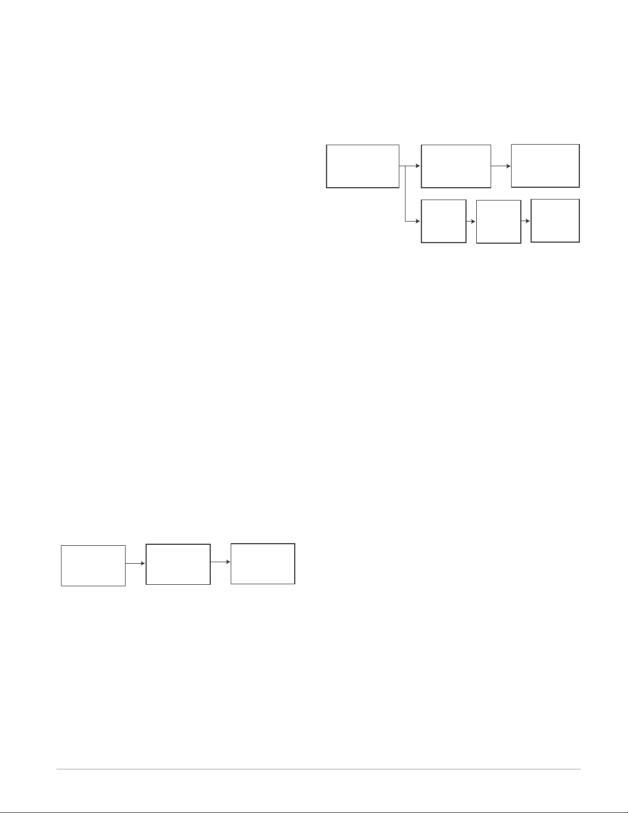
RMC module
- The logic block (within the RME module) is configured as an OR function
- The RME output function is tied to the internal output of the logical OR function
When either process alarm is true (analog input value is greater than the alarm high set point, the realworld output connected to the RME will be driven on.
*
Analog
Input
Function
* RMC module
*
Control
Function
* RMC module
* *
Alarm
Function
* RME module
Logic
Function
* RME module
*
Output
Function
* RMC module
*
Output
Function
* RME module
Outputs
Outputs can perform various functions or actions in
response to information provided by a function, such
as a digital output to turn a light on or off, unlocking
a door; or turning on a buzzer.
Assign a function to an output in the Output
Menu or Digital Output Menu of the Setup Page.
Then select which instance of that function will drive
the selected output. For example, you might assign
an output to respond to an internal output of a compare function.
You can assign more than one output to respond
to a single instance of a function, e.g., alarm 2 could
be used to trigger a light connected to output 1 and a
siren connected to digital output 5.
Actions
Based on a given input (Digital I/O, Logic function,
etc..) the Action function can cause other functions to
occur. To name a few, silencing alarms, turn control
loops off and placing alarms in non-alarm state.
Current
Function
Alarm
Function
Output
Function
In the example above one can see the Current function on the left which is connected to a real-world
input device (CT) where on the far right the internal
output of the Alarm function is tied to the input of
the Output function where a real-world output device
is then driven such as a siren or a flashing light.
With a slight modification of the graphic above the
example below now ties the real-world analog inputs
from an RMC module directly to its PID control. The
RME module is using the same analog input to drive
an alarm function. For the sake of this example the
following is true:
- Within the RME two unique high process alarms
are configured for analog inputs 1 and 2 of the
Watlow EZ-ZONE® RME Module • 7 • Chapter 1 Overview
Page 11
A Conceptual View of RM Hardware Configurations
Due to the scalability and flexibility in the system
components a user has several options available in
the way that the hardware can be connected. Listed
below are a few examples.
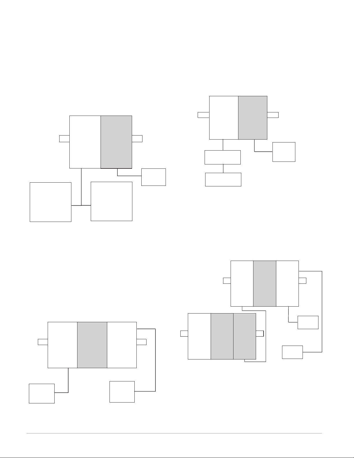
RM System Connected to a Remote User Interface
(RUI) and a PC
In this configuration the RUI and PC are connected
to the RM system via Watlow's Standard Bus where
both will be able to talk directly to any interconnected system module.
RM System Connected to an Operator Interface
Terminal (OIT) through an RUI/Gateway
In this configuration the HMI can be running any
of a number of protocols communicating to the RM
system through Watlow's RUI/Gateway. Available
protocols for the RUI/Gateway follow:
1. EtherNet/IP and or Modbus TCP
2. DeviceNet
3. Modbus RTU
4. Profibus DP
RM
ControlRMExpansion
RM
ControlRMExpansion
Slot CSlot C
Power
Supply
PC
EZ-ZONE
RUI
Configurator
The PC running EZ-ZONE Configurator software
and the RUI can be used to configure and then monitor both modules.
RM System Connected to a Programmable Logic Controller (PLC) on a DIN Rail
In this configuration the PLC can be connected to
the RM system via the Access module using one or
more available protocols:
1. EtherNet/IP and or Modbus TCP
2. DeviceNet
3. Modbus RTU
4. Profibus DP
RM
Control
RM
Expansion
RM
Access
Slot CSlot CSlot C
Slot E
Slot C
RUI/Gateway
OIT
Slot C
Power
Supply
RM System Connected to a Split Rail with OIT
In this configuration both the Inter-module Bus
(backplane communications) and Standard Bus are
connected between rails to allow for remote capabilities. It is recommended that the split rail connection
not exceed 200 feet. In this configuration the OIT
can communicate with all modules (maximum 16
modules any combination with one Access module).
RM
Access
Slot C
OIT
Slot E
Powe r
Supply
RM
Control
Slot C
RM
Expansion
Slot C
RM
Control
Slot C
RM
Expansion
Slot C
RM
Expansion
Slot C
Power
PLC
Supply
Watlow EZ-ZONE® RME Module • 8 • Chapter 1 Overview
Page 12
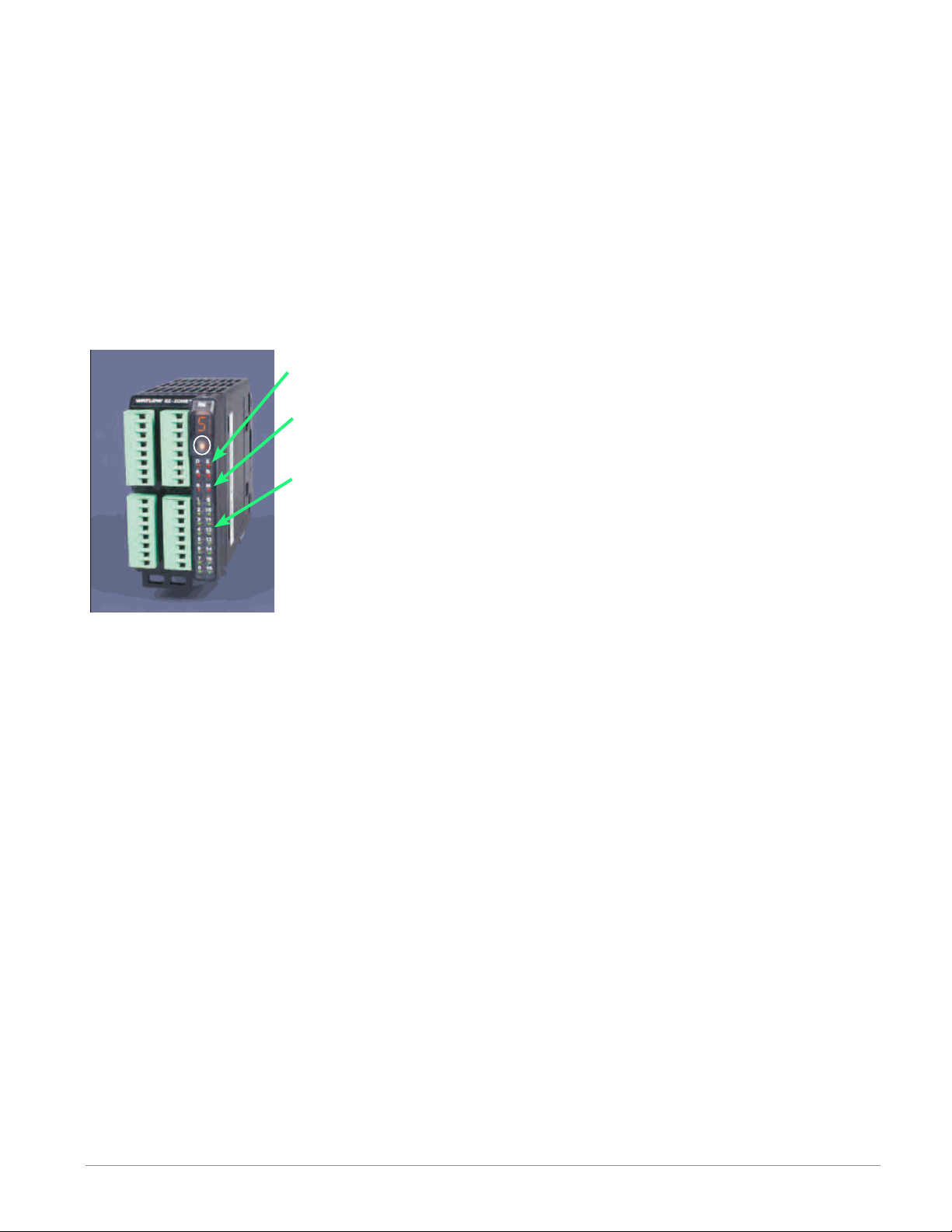
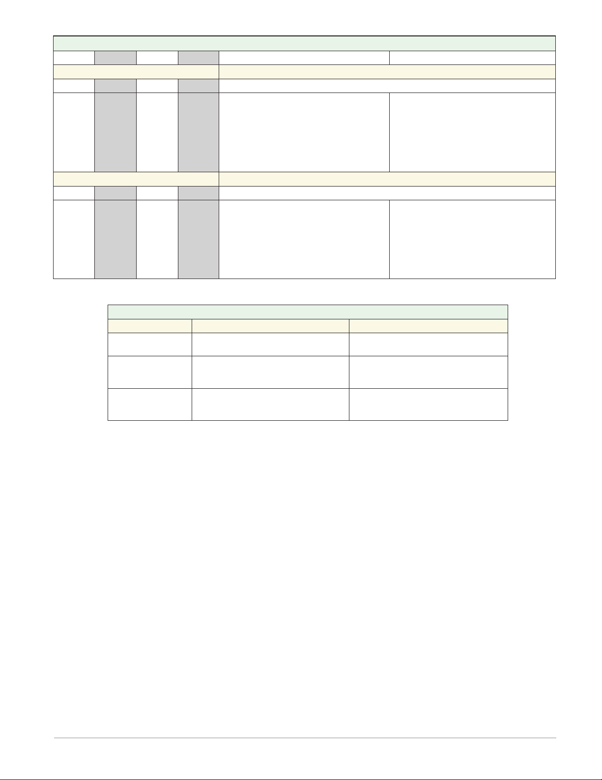
Module Orientation
The picture below represents one of six possible RM
modules. All six will have four slots on the face (slot
A, B, D, and E) and one on the bottom (slot C) not
shown. All of these slots are not always used on all
modules. On the face of the module there is a button
(white circle) under the Zone address (5) that when
pushed and held has the following functions:
1.For any module, push and hold for ~ 2 seconds. The
address will intensify indicating that it can now be
changed. Release and repeatedly press to change
to the desired unique address. Valid addresses over
Standard Bus range from 1 -16 (1 - 9, A is 10, B is
11, C is 12, D is 13, E is 14, F is 15, and h is 16).
The Access module is shipped at address J or 17
Module Status (Slot A,
B, D, or E)
Protocol (Standard
Bus - red
E
D
B
A
Module outputs 1
through 16, all may
or may not be used
depending on module
type
Watlow EZ-ZONE® RME Module • 9 • Chapter 1 Overview
Page 13
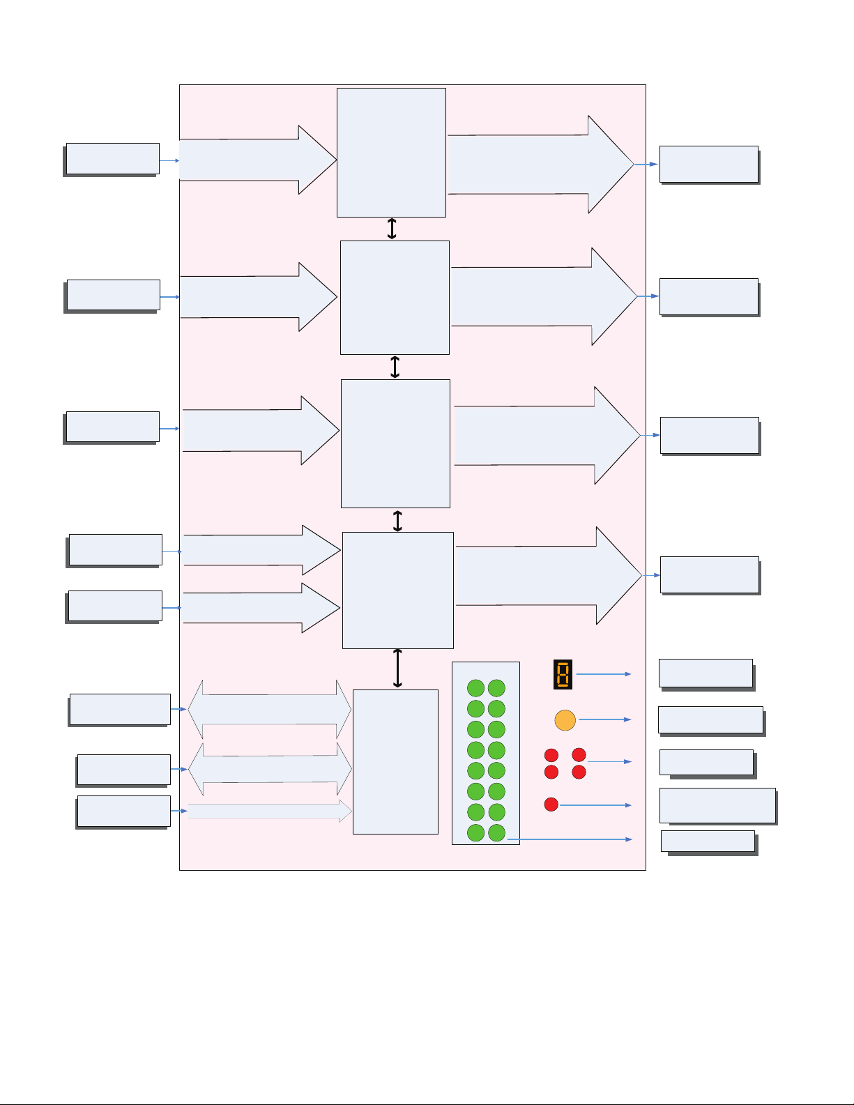
EZ-ZONE RM-Expansion Module - System Diagram
Input
Function
Input Device
Input Device
Input Device
Input Device
Input Device
RUI or PC
Other RM Modules
Power Supply
with up to 24 Inputs/Outputs
Digital Input (or output) 1 - 6
Switch contact or volts dc
Digital Input (or output) 7 - 12
Switch contact or volts dc
Digital Input (or output) 13 - 18
Switch contact or volts dc
Digital Input (or output) 19 - 24
Switch contact or volts dc
Current Transformer 19 - 22
EIA - 485 Communications
Standard Bus
Inter-module Bus
20.4 to 30.8 Vac or Vdc
3 - Universal/Retransmit
or
4 - 2A SSR
or
2 - 10A SSR
4 - 5A Mechanical Relays
or
or
6 Digital I/O
Slot A
3 - Universal/Retransmit
or
4 - 2A SSR
4 - 5A Mechanical Relays
or
or
6 Digital I/O
Slot B (optional)
3 - Universal/Retransmit
or
4 - 2A SSR
or
2 - 10A SSR
4 - Mechanical Relays
or
or
6 Digital I/O
Slot D (optional)
Current Transformer (CT)
or
6 Digital I/O
or
3 - Universal/Retransmit
or
4 - 2A SSR
Slot E (optional)
Standard Bus
Zone 1 - 16
Supervisory &
Power Board
Slot C
Output 1 - 6
None, Process, Switched dc/Open collector,
5A Mechanical Relay - Form A,
10A SSR - Form A, 2A SSR - Form A
Class 1 Div II not available
with mechanical relay
outputs.
Output 7 - 12
None, Process, Switched dc/Open collector,
5A Mechanical Relay - Form A, 2A SSR Form A
Class 1 Div II not available
with mechanical relay
outputs.
Output 13 - 18
None, Process, Switched dc/Open collector,
5A Mechanical Relay - Form A,
10A SSR - Form A, 2A SSR - Form A
Class 1 Div II not available
with mechanical relay
outputs.
Output 19 - 24
None, Process, Switched dc/Open collector,
2A SSR - Form A
Zone and Status
Output Status
LEDs
1
2
10
3
11
4
12
13
5
6
14
7
9
LED
Zone Selection
Button
D
A
S
E
B
81516
Output
Function
Off, Heat, Cool,
Alarm, Event
or Control
Off, Heat, Cool,
Alarm, Event
or Control
Off, Heat, Cool,
Alarm, Event
or Control
Off, Heat, Cool,
Alarm, Event
or Control
Indicates Zone
Address
Push to select Zone
Address
Card Status
Slots A, B, D, E
Indicates Standard Bus
communications activity
Indicates I/O
Status
Watlow EZ-ZONE® RME Module • 10 • Chapter 1 Overview
Page 14
2
147.07 mm
11
Module Removal Displacement
155 mm
11
al Displacement
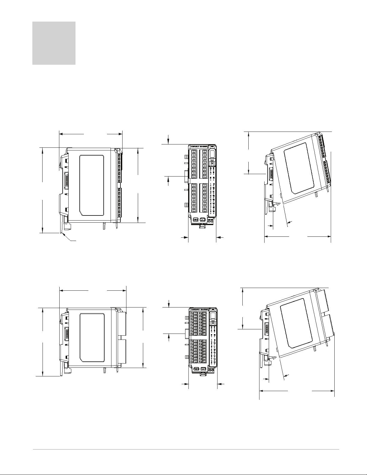
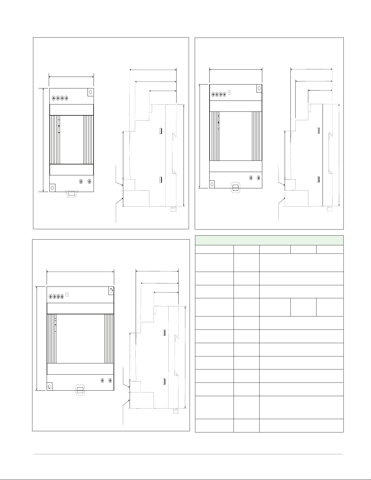
Chapter 2: Install and Wire
Dimensions
As can be seen below the dimensions of the RME modules will change slightly based on the type of connector
used.
Module Removal Clearance Standard Connectors
( 5.8 in )
75.08 mm
( 3.0 in )
15°
165 mm
( 6.50 in )
6.08 mm
( 4.57 in )
Latch in open position
44.45 mm
( 1.75 in )
101.60 mm
( 4.00 in )
51.56 mm
( 2.03 in )
Module Removal Clearance Straight Connectors
( 6.10 in )
75.08 mm
44.45 mm
( 1.75 in )
6.08 mm
( 4.57 in )
101.60 mm
( 4.00 in )
51.56 mm
( 2.03 in )
( 3.0 in )
15
°
173.90 mm
( 6.85 in )
Module Remov
Watlow EZ-ZONE® RME Module • 11 • Chapter 2 Install and Wire
Page 15
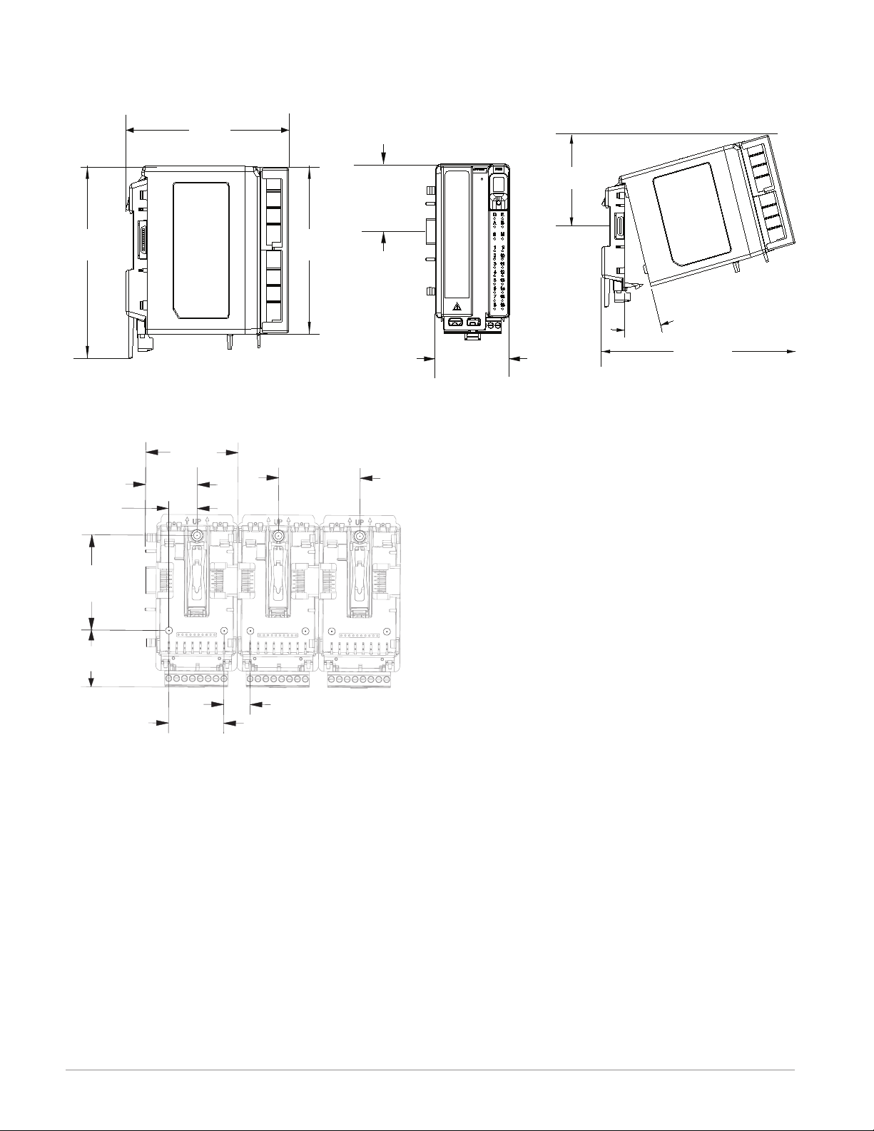
Dimensions
58.67 mm
60.45 mm
35.81 mm
(1.38 in)
11
Module Removal Clearance Ring Terminal Connectors
164.9 mm
( 6.5 in )
44.45 mm
( 1.75 in )
80.54 mm
( 3.17 in )
6.08 mm
( 4.57 in )
101.60 mm
( 4.00 in )
51.56 mm
( 2.03 in )
Chassis Mount Front View (Module Removed) - Screw Connection Pattern
(2.31 in)
51.56 mm
(2.03 in)
17.53 mm
(0.69 in)
(2.38 in)
32.77 mm
(1.29 in)
15°
184.58 mm
( 7.27 in )
Module Removal Displacement
(1.41 in)
16.76 mm
35.05 mm
(0.66 in)
The view above is representative of the modular backplane without the module.
Recommended chassis mount hardware:
1. #8 screw, 3/4" long
2. Torque to 10 -15 in-lb
3. No washers of any kind
Watlow EZ-ZONE® RME Module • 12 • Chapter 2 Install and Wire
Page 16
Power Supplies
DSP30
+ +
-
-
L N
DC LO
DC OK
123 4
5 6
53.00 mm
DSP30
2.087 in
91.00 mm
3.583 in
14.20 mm
9.75 mm
43.1 mm
91.00 mm
55.6 mm
49.00 mm
32.10 mm
0.559 in
1.697 in
0.384 in
3.583 in
2.189 in
1.929 in
1.264 in
DSP60
vout ADJ.
+ +
-
-
L N
DC LO
DC OK
123 4
5 6
DSP60
71.00 mm
2.795 in
91.00 mm
3.583 in
14.20 mm
9.75 mm
43.1 mm
91.00 mm
55.6 mm
49.00 mm
32.10 mm
0.559 in
1.697 in
0.384 in
3.583 in
2.189 in
1.929 in
1.264 in
DSP100
DC LO
DC OK
vout ADJ.
+ +
-
-
L N
123 4
5 6
DSP100
89.9 mm
3.539 in
91.00 mm
3.583 in
5
14.20 mm
9.75 mm
43.1 mm
91.00 mm
56.8 mm
49.00 mm
32.10 mm
0.559 in
1.697 in
0.384 in
3.583 in
2.236 in
1.929 in
1.264 in
Power Supply Specifications
DSP 30 DSP60 DSP10 0
AC Input Volt-
age Range
Input Fre-
quency
DC Input Volt-
age range
VAC
Hz 47 - 63Hz
VDC 120 - 370VDC
Inrush Cur-
rent (115 /
A 25 / 50A 30 / 60A 30 / 60A
230VAC)
Output Volt-
age Accuracy
Over voltage
Protection
LED Indica-
tors
Operating
Temperature
Storage Tem-
perature
Operating Hu-
midity
Vibration (Op-
erating)
Safety Agency
Certifications
% ±1% of Nominal
V 120 - 145%
- - - -
- - - -
- - - - -25 to +85°C
- - - - 20 - 95% RH (non condensing)
- - - -
- - - -
For a comprehensive listing of these specifications point your
browser to : http://us.tdk-lambda.com/lp/products/dsp-series.htm
90 - 264VAC, Class II double in-
sulated (No ground connection
required)
Green LED = On, Red LED = DC
Output Low
-25 to +71°C (Derate linearly
2.5%/°C from 55 to 71°C)
IEC 60068-2-6 (Mounting by rail:
Random wave, 10-500 Hz, 2G, ea.
along X, Y, Z axes 10 min/cycle,
60 min)
UL1310 Class 2(1), UL508 Listed,
UL60950-1, EN60950-1, CE
Watlow EZ-ZONE® RME Module • 13 • Chapter 2 Install and Wire
Page 17
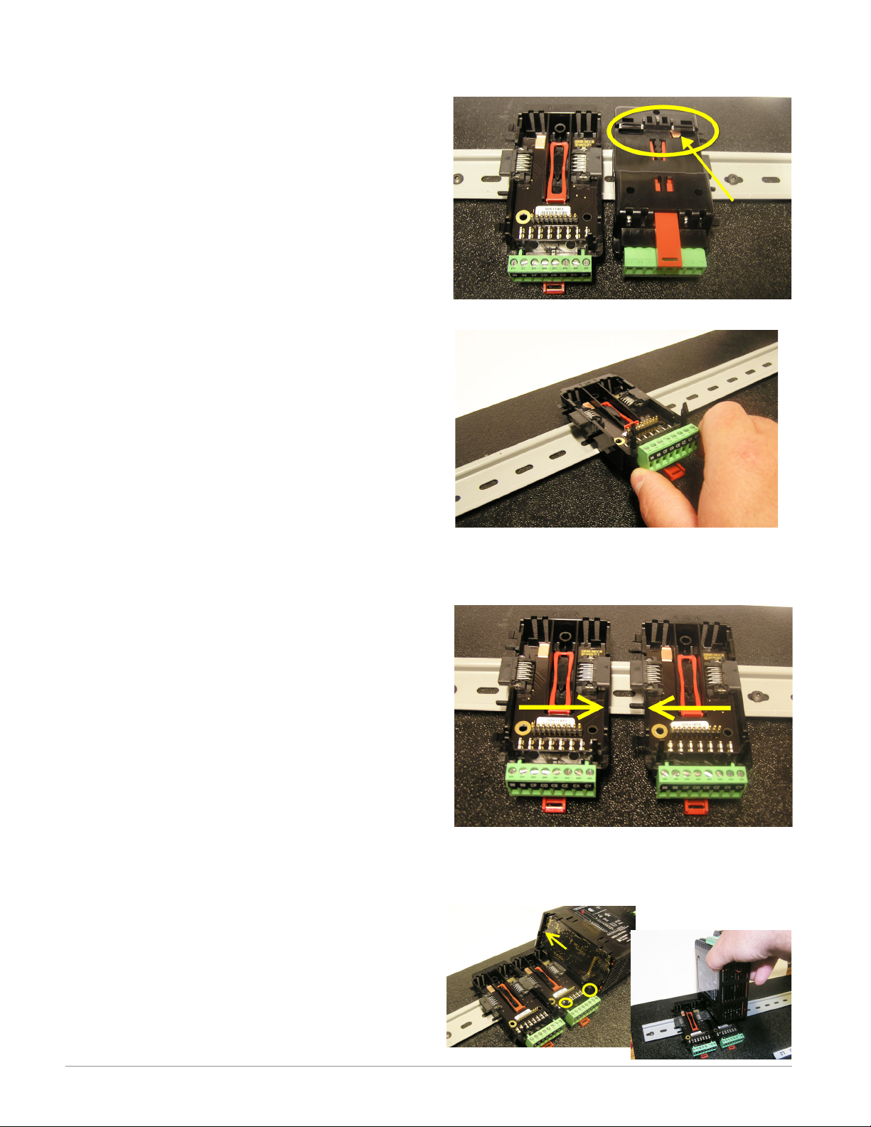
RME Installation and Removal on a DIN Rail
Modular Backplane Connector
The picture on the right shows the Modular Backplane
Connector, both front and rear view. The rear view
is bringing in to focus a metal clip. If the DIN rail is
grounded the Modular Backplane Connector and the
module connected to it will be also (recommended).
Installing the Modular Backplane Connector
Step 1
Hook backplane assembly to upper edge of DIN rail,
(see rear view above, backplane hook detail that
mates with upper rail edge is circled)
Step 2
Next, rotate back plane assembly downward to en
gage the lower edge of the rail. (Note: Din Rail clip ping distance ranges from 1.366 -1.389 inches. The
back plane assembly will not latch onto the rail suc cessfully if the rail is out of dimension).
Step 3
For final positioning and locking, the red tab is to
be pushed upward to further engage the bottom
edge of the rail with an over center snap action
latch. (The red locking tab protrudes from the bot tom side of the back plane assembly).
Installing Multiple Modular Backplane Connectors
Multiple modules are easily aligned and latched together. Each module includes matched mating geometry that facilitates accurate and consistent interconnections. The recommended method of multi-module
attachment is to first attach individual modules to
the rail separately and second to laterally slide the
modules together until they touch. (Refer to steps 1&2
above). When the multi-module system is attached and
laterally positioned to the desired placement the locking tab should be engaged to secure the control system
to the rail, (Refer to step 3 above).
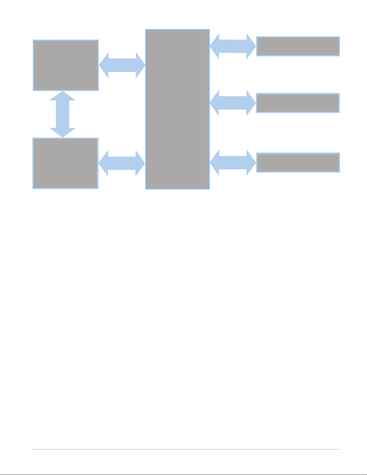
Module Installation
In the picture to the right notice that the arrow is
pointing at the top lip of the module (on side). When installing the module simply slide this lip over the top of
the Modular Backplane Connector and then push down
on the rear of the module where it will seat on the two
posts just above the green connector.
Watlow EZ-ZONE® RME Module • 14 • Chapter 2 Install and Wire
Page 18
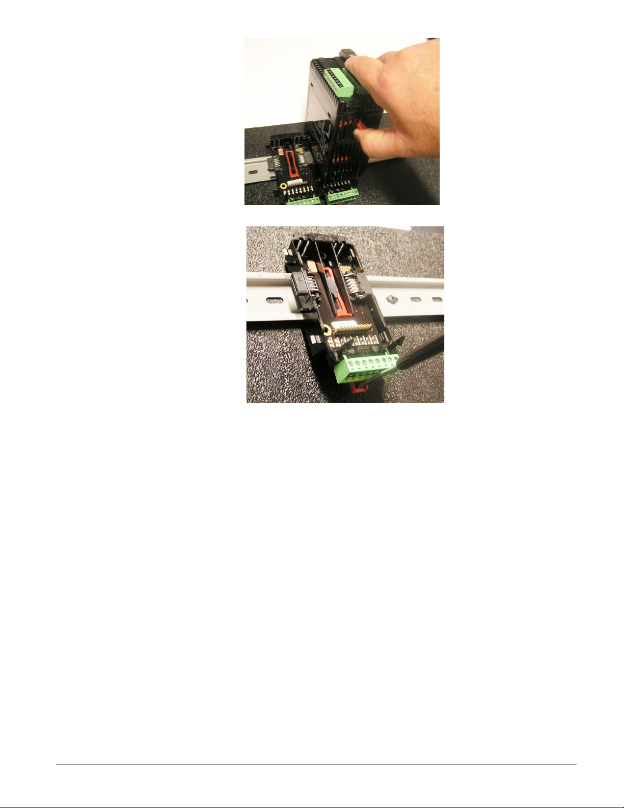
Module Removal
To remove a module from the
Modular Backplane Connector
find the red tab protruding from
the bottom of the module and
pull back on it as shown to the
right. While pulling back on the
red tab the two mounting posts
will release the module where the
module can then be lifted up and
out of the Modular Backplane
Connector.
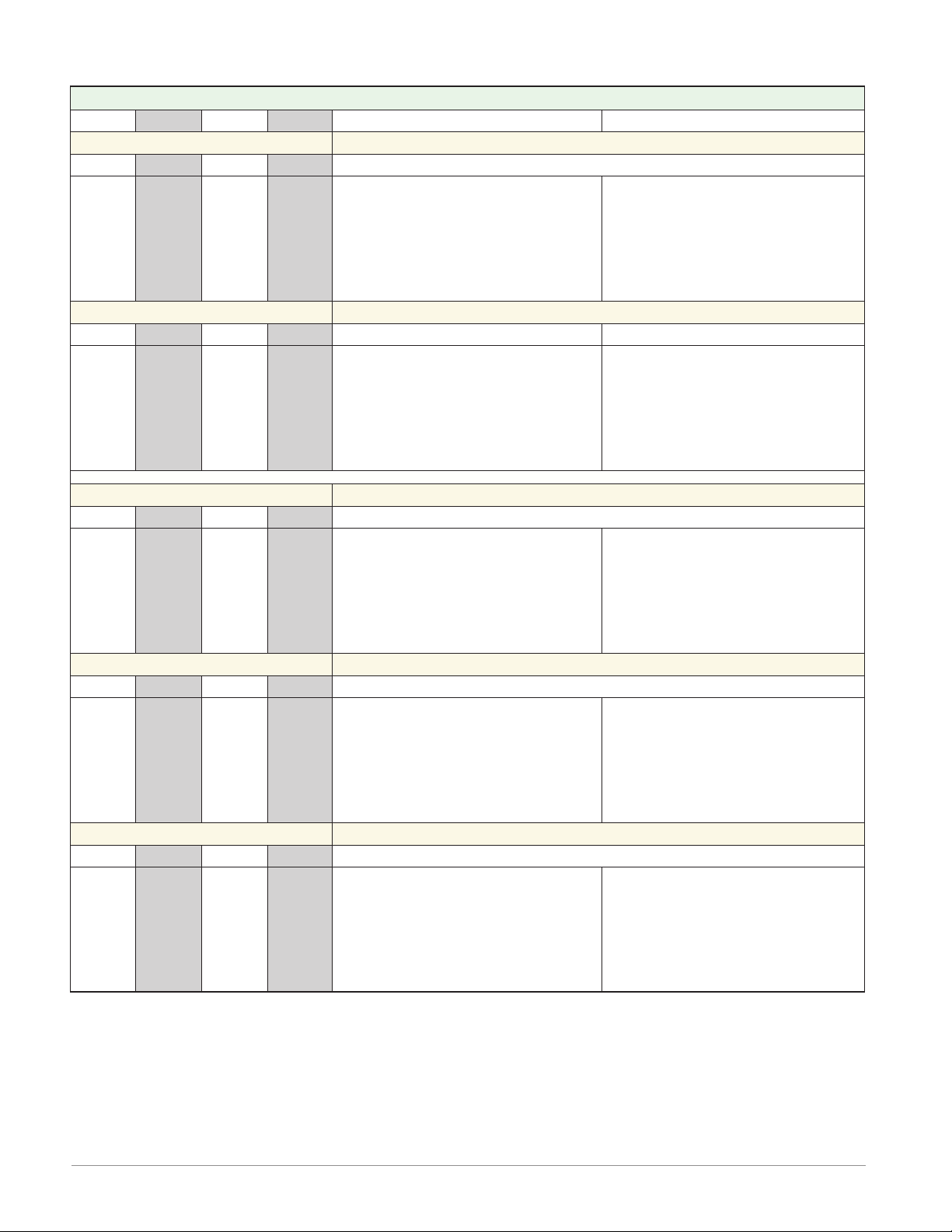
Removal of the Modular Backplane Connector
A module can be removed from
the Modular Backplane Connector
by inserting a screw driver into
the red locking tab just behind
the green connector and applying
downward pressure on the tab by
lifting the screwdriver upwards.
When released, the tab will move
downward and the connector can
then be lifted up off of the DIN
rail.
Watlow EZ-ZONE® RME Module • 15 • Chapter 2 Install and Wire
Page 19
Wiring
Expansion Module (RME x - x x x x - x x x x)
Slot A Slot B Slot D Slot E Terminal Function Configuration
Inputs Digital Inputs
1 - 6 7 - 12 13 - 18 19 - 24
B1
D1
D2
D3
D4
D5
D6
Z1
- - - - - - - - - 13 - 16
- - -
- - -
- - -
- - -
- - -
- - -
- - -
- - -
B7
D7
D8
D9
D10
D11
D12
Z7
- - -
- - -
- - -
- - -
- - -
- - -
- - -
- - -
B13
D13
D14
D15
D16
D17
D18
Z13
- - -
- - -
- - -
- - -
- - -
- - -
- - -
- - -
B19
D19
D20
D21
D22
D23
D24
Z19
T13
S13
T14
S14
T15
S15
T16
S16
Common
dc+ input
dc+ input
dc+ input
dc+ input
dc+ input
dc+ input
Internal Supply
mA ac
mA ac
mA ac
mA ac
mA ac
mA ac
mA ac
mA ac
6 Digital Inputs
Part # Digits 5, 6, 7, 8
Slot A: RME _ - [C] _ _ _ - _ _ _ _
Slot B: RME _ - _ [C] _ _ - _ _ _ _
Slot D: RME _ - _ _ [C] _ - _ _ _ _
Slot E: RME _ - _ _ _ [C] - _ _ _ _
Current Transformer Inputs
Quad Current Transformers
Part # Digit 8
Slot E: RME _ - _ _ _ [T] - _ _ _ _
Outputs
1 - 6 7 - 12 13 - 18 19 - 24
B1
D1
D2
D3
D4
D5
D6
Z1
1 - 4 7 - 10 13 - 16 19 - 22
L1
K1
L2
- - -
- - L3
K3
L4
1 - 3 7 - 9 13 - 15 19 - 21
F1
H1
- - F2
H2
- - F3
H3
B7
D7
D8
D9
D10
D11
D12
Z7
L7
K7
L8
- - -
- - L9
K9
L10
F7
H7
- - F8
H8
- - F9
H9
B13
D13
D14
D15
D16
D17
D18
Z13
L13
K13
L14
- - -
- - L15
K15
L16
F13
H13
- - F14
H14
- - F15
H15
B19
D19
D20
D21
D22
D23
D24
Z19
L19
K19
L20
- - -
- - -
L21
K21
L22
F19
H19
- - -
F20
H20
- - -
F21
H21
common
open collector/ switched dc
open collector/ switched dc
open collector/ switched dc
open collector/ switched dc
open collector/ switched dc
open collector/ switched dc
internal supply
4, 2A Solid-State Relay (SSR) Outputs
normally open
common
normally open
not used
not used
normally open
common
normally open
Tri-State Process/Retransmit Outputs
voltage or current voltage + or current +
not used
voltage or current voltage + or current +
not used
voltage or current voltage + or current +
Digital Outputs
Digital Inputs
Part # Digits 5, 6, 7, 8
Slot A: RME _ - [C] _ _ _ - _ _ _ _
Slot B: RME _ - _ [C] _ _ - _ _ _ _
Slot D: RME _ - _ _ [C] _ - _ _ _ _
Slot E: RME _ - _ _ _ [C] - _ _ _ _
2A SSR Outputs
Part # Digits 5, 6, 7, 8
Slot A: RME _ - [L] _ _ _ - _ _ _ _
Slot B: RME _ - _ [L] _ _ - _ _ _ _
Slot D: RME _ - _ _ [L] _ - _ _ _ _
Slot E: RME _ - _ _ _ [L] - _ _ _ _
Tri-Process Outputs
Part # Digits 5, 6, 7, 8
Slot A: RME _ - [F] _ _ _ - _ _ _ _
Slot B: RME _ - _ [F] _ _ - _ _ _ _
Slot D: RME _ - _ _ [F] _ - _ _ _ _
Slot E: RME _ - _ _ _ [F] - _ _ _ _
Watlow EZ-ZONE® RME Module • 16 • Chapter 2 Install and Wire
Page 20
Expansion Module (RME x - x x x x - x x x x)
Slot A Slot B Slot D Slot E Terminal Function Configuration
Outputs (cont.)
1 - 2 - - - 13 - 14 - - -
L1
L1
K1
K1
L2
L2
K2
K2
1 - 4 7 - 10 13 - 16 - - -
L1
K1
L2
K2
L3
K3
L4
K4
- - -
- - -
- - -
- - -
- - -
- - -
- - -
- - -
L7
K7
L8
K8
L9
K9
L10
K10
L13
L13
K13
K13
L14
L14
K14
K14
L13
K13
L14
K14
L15
K15
L16
K16
Slot C Terminal Function Configuration
98
99
CF
CD
CE
CZ
CX
CY
- - -
- - -
- - -
- - -
- - -
- - -
- - -
- - -
- - -
- - -
- - -
- - -
- - -
- - -
- - -
- - -
Power input: ac or dc+
Power input: ac or dc-
Standard Bus EIA-485 common
Standard Bus EIA-485 T-/RStandard Bus EIA-485 T+/R+
Inter-module Bus
Inter-module Bus
Inter-module Bus
normally open
normally open
common
common
normally open
normally open
common
common
4, 5A Form A Mechanical Relay Outputs
normally open
common
normally open
common
normally open
common
normally open
common
Power and Communications
2, 10A Form A SSR Outputs
10A SSR Outputs
Part # Digits 5, 7
Slot A: RME _ - [K] _ _ _ - _ _ _ _
Slot B: Not available
Slot D: RME _ - _ _ [K] _ - _ _ _ _
Slot E: Not available
5A Mechanical Relay Outputs
Part # Digits 5, 6, 7
Slot A: RME _ - [J] _ _ _ - _ _ _ _
Slot B: RME _ - _ [J] _ _ - _ _ _ _
Slot D: RME _ - _ _ [J] _ - _ _ _ _
Slot E: Not available
All
Standard Bus
Inter-module Bus
Watlow EZ-ZONE® RME Module • 17 • Chapter 2 Install and Wire
Page 21
All Modules - Front View -
Standard Connector
Slot D
Slot A
Slot E
Slot B
Slot C
98 99
power
Watlow EZ-ZONE® RME Module • 18 • Chapter 2 Install and Wire
Page 22
RME System Isolation Blocks
Controller Power Supply
20.4 to 30.8VÎ (dc)
20.4 to 30.8VÅ (ac)
Safety Isolation
Mechanical Relay,
Solid-State Relay,
Outputs
Safety Isolation
Safety Isolation
Controller
Low Voltage Power Bus
Low-voltage Isolation: 42V peak
Safety Isolation: 1,528VÅ (ac)
No Isolation
No Isolation
Low-voltage
Isolation
Digital Inputs & Outputs
Switched DC, Open Collector,
Process outputs
Communications Ports
Watlow EZ-ZONE® RME Module • 19 • Chapter 2 Install and Wire
Page 23
Warning: ç
S
l
o
t
C
S
l
o
t
C
s
Slot E
Use National Electric (NEC) or other
country-specific standard wiring and
safety practices when wiring and
connecting this controller to a power
source and to electrical sensors or peripheral devices. Failure to do so may
result in damage to equipment and
property, and/or injury or loss of life.
Note:
Maximum wire size termination
and torque rating:
• 0.0507 to 3.30 mm2 (30 to 12
AWG) single-wire termination
or two 1.31 mm2 (16 AWG)
• 0.8 Nm (7.0 in-lb.) torque
Note:
Adjacent terminals may be labeled differently, depending on
the model number.
Note:
To prevent damage to the controller, do not connect wires to
unused terminals.
Note:
Maintain electrical isolation
between digital input-outputs,
switched dc/open collector outputs and process outputs
prevent ground loops.
to
Note:
If the last two digits of the part
number are "12", this Equipment is suitable for use in
CLASS I, DIVISION 2, Groups
A, B, C and D or Non-Hazardous locations
Code T4
only. Temperature
Warning: ç
Explosion Hazard – Substitution of
component may impair suitability for
CLASS I, DIVISION 2.
Warning: ç
Explosion Hazard - Do not disconnect
while the circuit is live or unless the
area is known to be free of ignitable
concentrations of flammable substances.
Expansion Module Wiring (RMEx-xxxx-xxxx)
Low Power RME - All Model Numbers
• 20.4 to 30.8 V Å (ac) / Î (dc) 14VA
• 47 to 63 Hz
• Expansion module power consumption, 7 Watts maximum
• 31 Watts maximum power available for P/S part #:0847-02990000
98
99
power
• 60 Watts maximum power available for P/S part #:0847-03000000
• 91 Watts maximum power available for P/S part #:0847-03010000
• Class 2 or SELV power source required to meet UL compliance
standards
Communications
• CF, CD, CE - Standard Bus EIA485 Communications
• CZ, CX, CY - Inter-module Bus EIA485 Communications
• Do not route network wires with power wires. Connect network wires in daisy-chain fashion when connecting multiple
devices in a network
CF CD CE CZ CX CY
Standard Bus
Common
T- / R-
T+ / R+
Inter-module Bu
Common
-
+
Quad Current Transformer Inputs 13, 14, 15 and 16
RME Part # Digit 8 is T
• Input range is 0 to 50 mA (ac).
T13
S13
T14
S14
T15
S15
T16
S16
• Current transformer part number: 160246
• 100 Ω input impedance
• Response time: 1 second maximum
• Accuracy +/-1 mA typical
Warning: ç
Explosion Hazard - Dry contact closure
Digital Inputs shall not be used in Class
I Division 2 Hazardous Locations unless
switch used is approved for this application.
Watlow EZ-ZONE® RME Module • 20 • Chapter 2 Install and Wire
Page 24
Slot A, B, D, E
Int
Slot A, B, D, E
y
n
Warning: ç
Use National Electric (NEC) or other
country-specific standard wiring and
safety practices when wiring and
connecting this controller to a power
source and to electrical sensors or peripheral devices. Failure to do so may
result in damage to equipment and
property, and/or injury or loss of life.
Note:
Maximum wire size termination
and torque rating:
• 0.0507 to 3.30 mm2 (30 to 12
AWG) single-wire termination
or two 1.31 mm2 (16 AWG)
• 0.8 Nm (7.0 in-lb.) torque
Note:
Adjacent terminals may be labeled differently, depending on
the model number.
Note:
To prevent damage to the controller, do not connect wires to
unused terminals.
Note:
Maintain electrical isolation
between digital input-outputs,
switched dc/open collector outputs and process outputs
prevent ground loops.
to
Note:
If the last two digits of the part
number are "12", this equipment is suitable for use in
CLASS I, DIVISION 2, Groups
A, B, C and D or Non-Hazardous locations
Code T4
only. Temperature
Warning: ç
Explosion Hazard – Substitution of
component may impair suitability for
CLASS I, DIVISION 2.
Warning: ç
Explosion Hazard - Do not disconnect
while the circuit is live or unless the
area is known to be free of ignitable
concentrations of flammable substances.
Quencharc Note:
Switching pilot duty inductive loads
(relay coils, solenoids, etc.) with the
mechanical relay, Solid-State relay or
open collector output options requires
use of an R.C. suppressor.
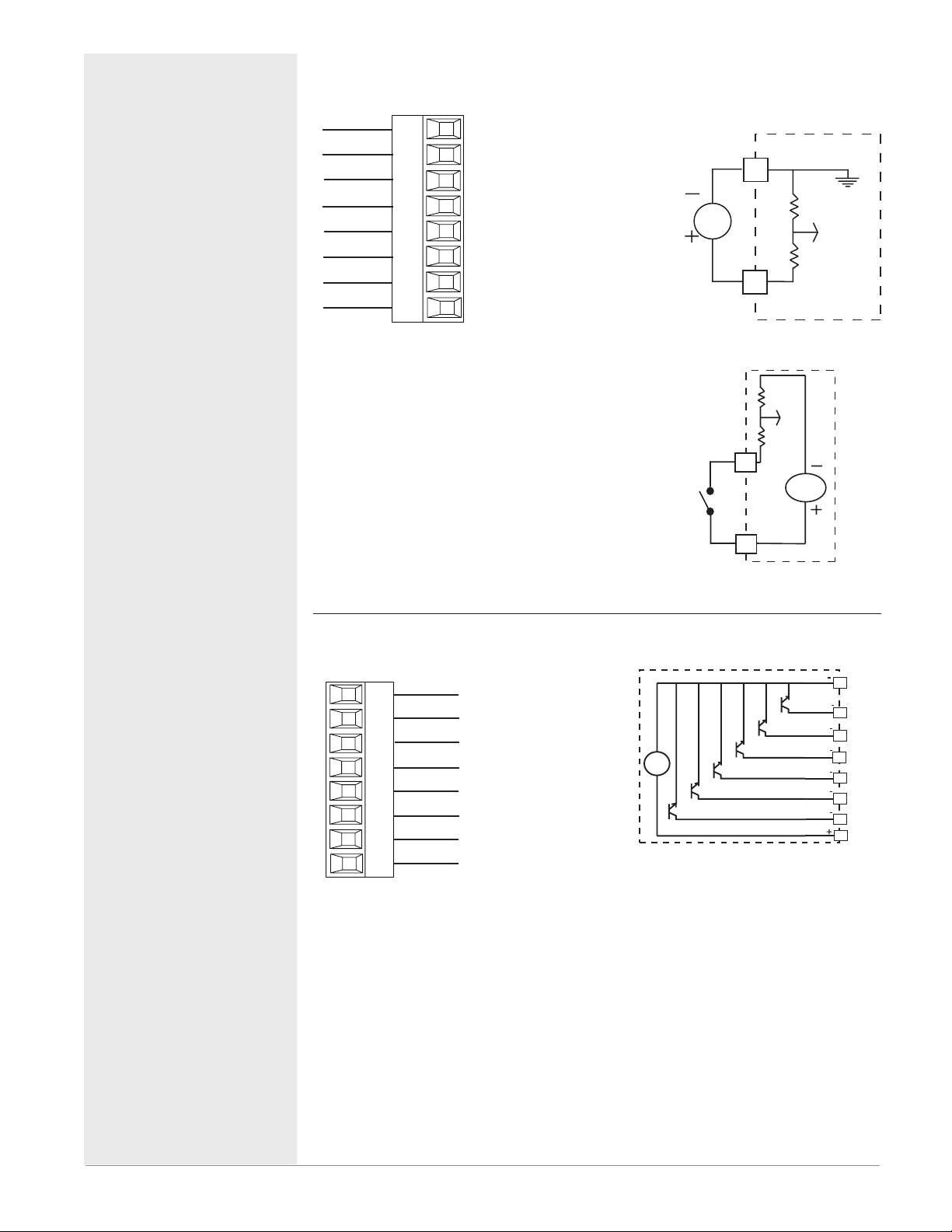
Digital Inputs 1 to 24
RME Part # Digit 5, 6, 7, 8 is C
Digital Input Event Condi-
Common
DC Input
DC Input
DC Input
DC Input
DC Input
DC Input
ernal Supply
B_
D_
D_
D_
D_
D_
D_
Z_
tions
• Dry Contact
- Input inactive when >
100KΩ
- Input active when <
50Ω
• Voltage
- Input inactive when <
2V
- Input active when > 3V
• Six user configurable
Digital Inputs per slot
Digital Outputs 1 to 24
RME Part # Digit 5, 6, 7, 8 is C
Common
B_
Collector out
D_
Collector out
D_
Collector out
D_
D_
D_
D_
Z_
Collector out
Collector out
Collector out
Internal Suppl
• Maximum switched
voltage is 32VÎ
(dc)
• Internal supply
provides a constant
power output of
750mW
• Maximum output
sink current per
output is 1.5A (external class 2 or
*SELV supply required)
• Total sink current
for all outputs not
to exceed 8A
• Do not connect outputs in parallel
*Safety Extra Low
Voltage
Voltage Input
common
B_
Vdc
D_
Dry Contact
D_
24 Vdc
Z_
B_
Commo
D_
D_
Vdc
• Six user configurable Digital Outputs per slot
D_
D_
D_
D_
Internal
Z_
Supply
Watlow EZ-ZONE® RME Module • 21 • Chapter 2 Install and Wire
Page 25
Warning: ç
Slot A, B, D
Use National Electric (NEC) or other
country-specific standard wiring and
safety practices when wiring and
connecting this controller to a power
source and to electrical sensors or peripheral devices. Failure to do so may
result in damage to equipment and
property, and/or injury or loss of life.
Note:
Maximum wire size termination
and torque rating:
• 0.0507 to 3.30 mm2 (30 to 12
AWG) single-wire termination
or two 1.31 mm2 (16 AWG)
• 0.8 Nm (7.0 in-lb.) torque
Note:
Adjacent terminals may be labeled differently, depending on
the model number.
Note:
To prevent damage to the controller, do not connect wires to
unused terminals.
Note:
Maintain electrical isolation
between digital input-outputs,
switched dc/open collector outputs and process outputs
prevent ground loops.
to
Note:
If the last two digits of the part
number are "12", this Equipment is suitable for use in
CLASS I, DIVISION 2, Groups
A, B, C and D or Non-Hazardous locations
Code T4
only. Temperature
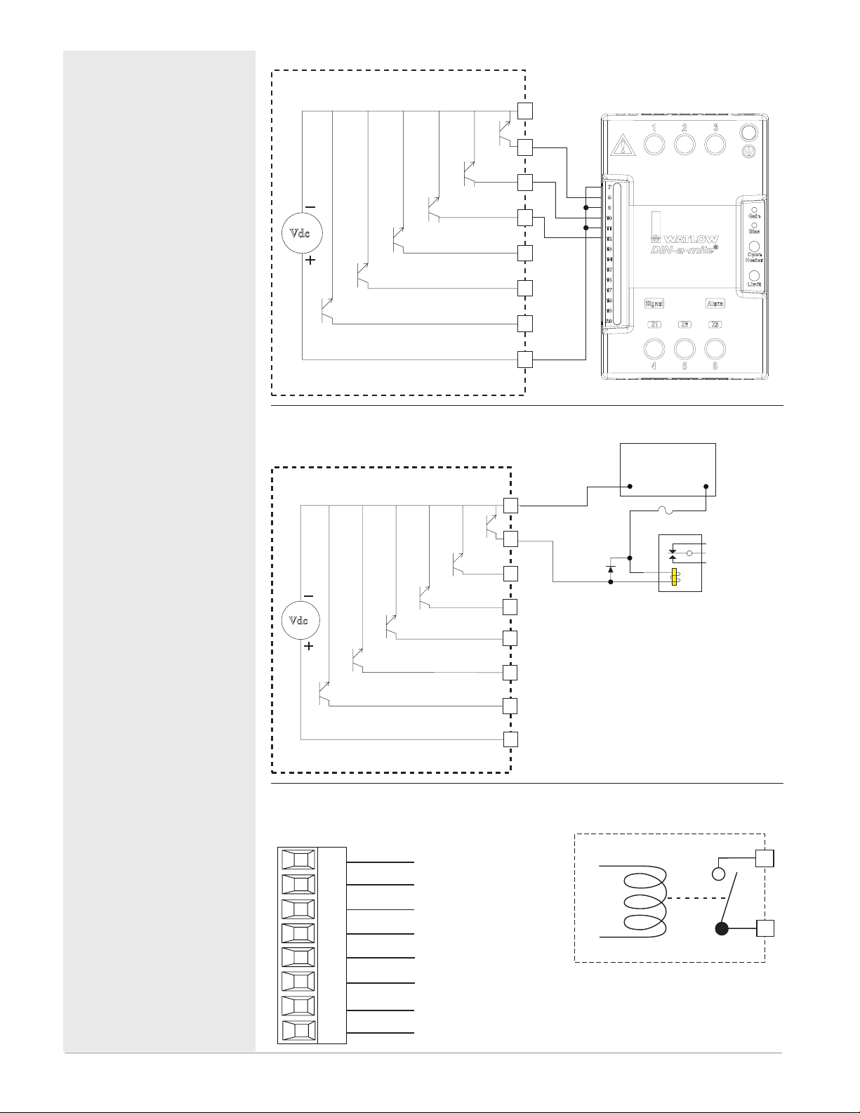
Digital Output (
Vdc
Internal Circuitry
Digital Output (
Collector Outputs
Vdc
1 to 24)
Collector Outputs
1 to 24)
Wiring Example -
Wiring Example - Open Collector
Common
B_
D_
D_
D_
D_
D_
D_
Z_
Internal Supply
Common
B_
D_
D_
D_
D_
Switched DC to DIN-A-MITE
Htr 1
+
-
Htr 2
Htr 3
+
-
+
-
DC90-60C0-0000
Power Supply
5 to 32 Vdc
-
Fuse
Diode
+
An example fuse is
Bussmann AGC-1 1/2
Relay
®
Warning: ç
Explosion Hazard – Substitution of
component may impair suitability for
CLASS I, DIVISION 2.
Warning: ç
Explosion Hazard - Do not disconnect
while the circuit is live or unless the
area is known to be free of ignitable
concentrations of flammable substances.
Quencharc Note:
Switching pilot duty inductive loads
(relay coils, solenoids, etc.) with the
mechanical relay, Solid-State relay or
open collector output options requires
use of an R.C. suppressor.
Internal Circuitry
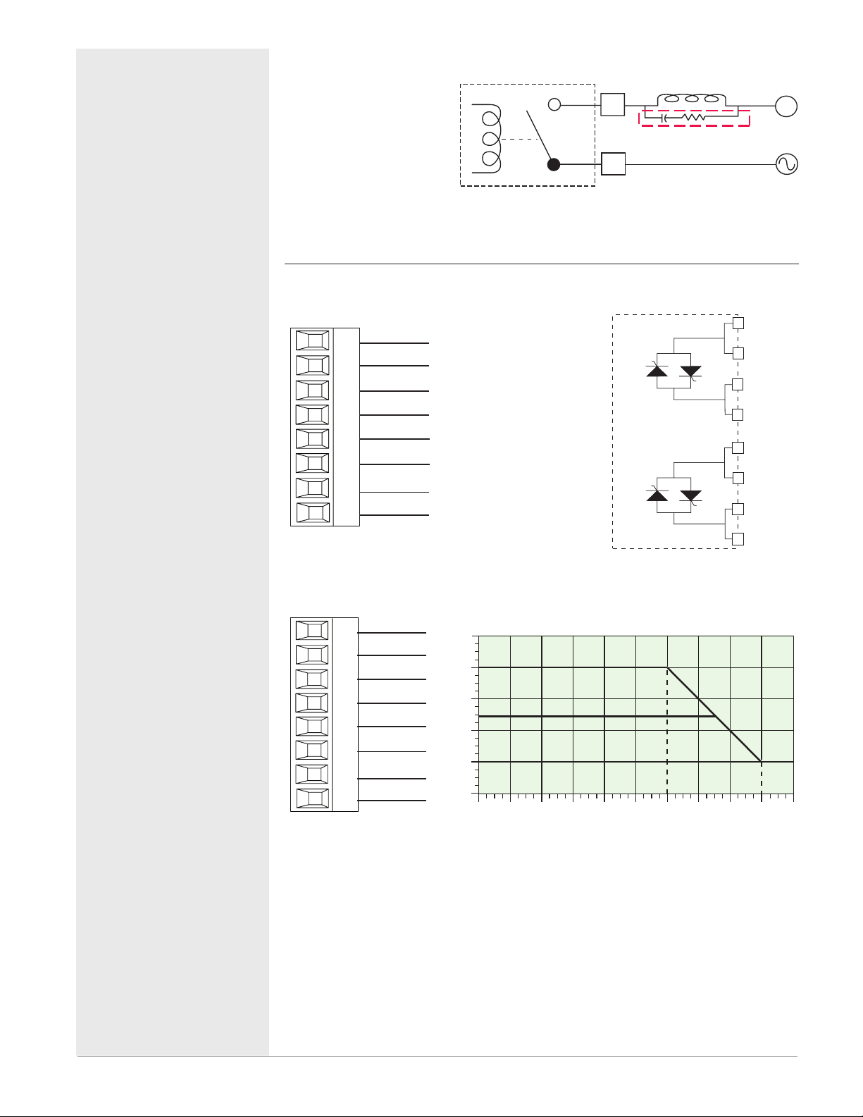
Quad Mechanical Relays, Form A Outputs 1-4, 7-10, 13-16
RME Part # Digit 5, 6, or 7 is J
• 5 A at 240V (ac) or 30V
normally open
L_
common
K_
normally open
L_
common
K_
normally open
L_
common
K_
normally open
L_
common
K_
(dc) maximum resistive
load
• 20 mA at 24V minimum
load
• 125VA pilot duty at
120/240V (ac), 25 VA at
24V (ac)
• 100,000 cycles at rated
load
• output does not supply
power
• For use with ac or dc
• Not available in slot E
• See Quencharc note.
D_
D_
Z_
Internal Supply
L_
K_
Watlow EZ-ZONE® RME Module • 22 • Chapter 2 Install and Wire
Page 26
Quencharc Wiring Example
User Load
Slot A
Open
Slot D
Output Amps
70
25
Warning: ç
Use National Electric (NEC) or other
country-specific standard wiring and
safety practices when wiring and
connecting this controller to a power
source and to electrical sensors or peripheral devices. Failure to do so may
result in damage to equipment and
property, and/or injury or loss of life.
Note:
Maximum wire size termination
and torque rating:
• 0.0507 to 3.30 mm2 (30 to 12
AWG) single-wire termination
or two 1.31 mm2 (16 AWG)
• 0.8 Nm (7.0 in-lb.) torque
Note:
Adjacent terminals may be labeled differently, depending on
the model number.
Note:
To prevent damage to the controller, do not connect wires to
unused terminals.
Note:
Maintain electrical isolation
between digital input-outputs,
switched dc/open collector outputs and process outputs
prevent ground loops.
to
Note:
If the last two digits of the part
number are "12", this equipment is suitable for use in
CLASS I, DIVISION 2, Groups
A, B, C and D or Non-Hazardous locations
Code T4
only. Temperature
Warning: ç
Explosion Hazard – Substitution of
component may impair suitability for
CLASS I, DIVISION 2.
Warning: ç
Explosion Hazard - Do not disconnect
while the circuit is live or unless the
area is known to be free of ignitable
concentrations of flammable substances.
In this example the
Quencharc circuit (Watlow
part# 0804-0147-0000) is
used to protect the RME
internal circuitry from the
counter electromagnetic force
from the inductive user load
when de-engergized. It is
recommended that this or an
equivalent Quencharc be used
when connecting inductive
loads to the RME outputs.
Dual 10A SSR Outputs 1-4
RME Part # Digit 5 or 7 is K
• Maximum resistive load 10
normally open
L1
normally open
L1
common
K1
K1
L2
L2
K2
K2
L13
L13
K13
K13
L14
L14
K14
K14
common
normally open
normally open
common
common
normally open
normally open
common
common
normally open
normally open
common
common
A per output @ 240V (ac)
• Maximum 20 A per slot @
50 0C
• Maximum 12 A per slot @
65 0C
Total Output Amps Per Slot
20
15
10
5
0
20
25
_
L
Quencharc
_
K
12 A
403530
50
45
Ambient Temperatue (oC)
55
N
L_
Normally
L_
K_
Common
K_
L_
Normally Open
L_
K_
Common
K_
60 65
Watlow EZ-ZONE® RME Module • 23 • Chapter 2 Install and Wire
Page 27
Warning: ç
Slot D, E
y Open
y Open
y Open
y Open
Quad 2 Amp SSR Derating Curve
Amps per Output
s
Slot A, B, D, E
current +
Use National Electric (NEC) or other
country-specific standard wiring and
safety practices when wiring and
connecting this controller to a power
source and to electrical sensors or peripheral devices. Failure to do so may
result in damage to equipment and
property, and/or injury or loss of life.
Note:
Note:
Note:
Note:
Note:
Warning: ç
Explosion Hazard – Substitution of
component may impair suitability for
CLASS I, DIVISION 2.
Warning: ç
Explosion Hazard - Do not disconnect
while the circuit is live or unless the
area is known to be free of ignitable
concentrations of flammable substances.
Maximum wire size termination
and torque rating:
• 0.0507 to 3.30 mm2 (30 to 12
AWG) single-wire termination
or two 1.31 mm2 (16 AWG)
• 0.8 Nm (7.0 in-lb.) torque
Adjacent terminals may be labeled differently, depending on
the model number.
To prevent damage to the controller, do not connect wires to
unused terminals.
Maintain electrical isolation
between digital input-outputs,
switched dc/open collector outputs and process outputs
to
prevent ground loops.
If the last two digits of the part
number are "12", this Equipment is suitable for use in
CLASS I, DIVISION 2, Groups
A, B, C and D or Non-Hazardous locations
only. Temperature
Code T4
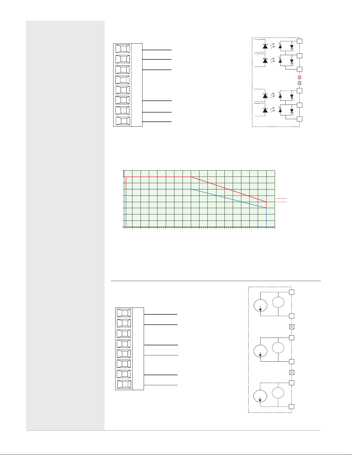
Quad 2A SSR Outputs 1-4, 7-10, 13-16, 19 - 22
RME Part # Digit 5, 6, 7, 8 is L
• 2 A at 20 to 264VÅ (ac)
normally open
L_
common
K_
normally open
L_
maximum resistive load
• 50 VA 120/240VÅ (ac) pilot
duty
• Optical isolation, without
contact suppression
• maximum off state leakage
of 105 microamperes
normally open
L_
common
K_
normally open
L_
• Output does not supply
power.
• Do not use on dc loads.
• N.O., COM, N.O wiring
(shared common) between
each set of outputs.
• 100,000 cycle endurance
tested resistive and pilot
duty.
• See Quencharc note.
2.25
1.50
1.25
0.75
0.50
0.25
2.00
1.75
1.0
0
-15
-20
0-5-10
All Outputs 100% Duty Cycle
10
15
5
Ambient Temperature (oC)
20
25 30 35 40
45 50 55 60
70
65
Note:
Each of the four SSR outputs has internal circuitry that will protect it from over
heating. Outputs may be disabled (shut off) automatically if internal temperatures
exceed those listed in the graph above. After the output temperature drops approximately 10 °C the outputs will once again be enabled for operation.
Tri-Process/Retransmit Outputs 1-3, 7-9, 13-15, 19-21
RME Part # Digit 5, 6, 7, 8 is F
0 to 10 V
Not Used
0 to 10 V
Not Used
0 to 10 V
volts or current -
F_
volts +/current +
H_
volts or current -
F_
volts +/current +
H_
volts or current -
F_
volts +/current +
H_
• 0 to 20 mA into 400Ω
maximum load
• 0 to 10VÎ (dc) into 4
kΩ minimum load
• Outputs are scalable
• Output supplies power
• Each output can be
independently set for
voltage or current.
• Output may be used
as retransmit or control.
0 to 20 mA
0 to 20 mA
0 to 20 mA
_
L
Normall
_
K
Common
_
L
Normall
Not Used
Not Used
_
L
Normall
_
K
Common
_
L
Normall
1 Quad SSR
Multiple Quad SSR Card
_
negative
F
volts +
or
_
H
current +
_
negative
F
volts +
or
_
H
current +
negative
_
F
volts +
_
or
H
Watlow EZ-ZONE® RME Module • 24 • Chapter 2 Install and Wire
Page 28
Warning: ç
Slot C
Use National Electric (NEC) or other
country-specific standard wiring and
safety practices when wiring and
connecting this controller to a power
source and to electrical sensors or peripheral devices. Failure to do so may
result in damage to equipment and
property, and/or injury or loss of life.
Note:
Maximum wire size termination
and torque rating:
• 0.0507 to 3.30 mm2 (30 to 12
AWG) single-wire termination
or two 1.31 mm2 (16 AWG)
• 0.8 Nm (7.0 in-lb.) torque
Note:
Adjacent terminals may be labeled differently, depending on
the model number.
Note:
To prevent damage to the controller, do not connect wires to
unused terminals.
Note:
Maintain electrical isolation
between digital input-outputs,
switched dc/open collector outputs and process outputs
to
prevent ground loops.
Note:
If the last two digits of the part
number are "12", this equipment is suitable for use in
CLASS I, DIVISION 2, Groups
A, B, C and D or Non-Hazardous locations
only. Temperature
Code T4
Warning: ç
Explosion Hazard – Substitution of
component may impair suitability for
CLASS I, DIVISION 2.
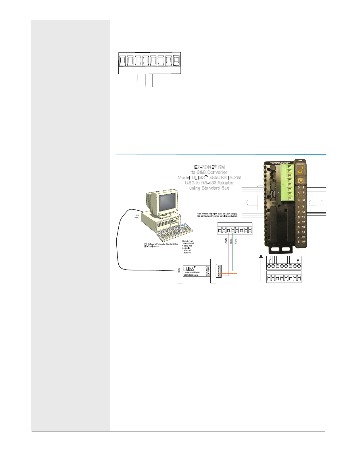
Standard Bus EIA-485 Communications
• Wire T-/R- to the A terminal of the EIA-485
port.
98 99 CF CD CE CZ CX CY
USB
Port
common
T+/R+
T-/R-
PC Software Protocol - Standard Bus
EZ-Configurator
• Wire T+/R+ to the B
terminal of the EIA-485
port.
• Wire common to the
common terminal of the
EIA-485 port.
• Do not route network
wires with power wires.
Connect network wires
in daisy-chain fashion
when connecting multiple devices in a network.
EZ-ZONE® RM
to B&B Converter
Model ULINX 485USBTB-2W
USB to RS-485 Adapter
using Standard Bus
Data format
38,400 baud
8 data bits
no parity
1 start bit
1 stop bit
TM
U
LINX
S
USB Serial Conversion
U
B
Model 485TB-2W
B B electronics
&
0847-0326-0000
TM
Use twisted pair wires such as Cat 5 cabling.
Do not route with power carrying conductors.
98 99
CF CD CE CZ CX CY
A(-)
B(+)
A(-)
B(+)
GND
• A 120 Ω termination resistor may be required
across T+/R+ and T-/R-,
placed on the last controller on the network.
• Do not connect more
than 16 EZ-ZONE RM
controllers on a network.
• maximum network
length: 1,200 meters
(4,000 feet)
• 1/8th unit load on EIA485 bus
S
l
t
o
C
98 99
CF CD CE CZ CX CY
Warning: ç
Explosion Hazard - Do not disconnect
while the circuit is live or unless the
area is known to be free of ignitable
Note:
Do not leave a USB to EIA-485 converter connected to Standard Bus without
power (i.e., disconnecting the USB end from the computer while leaving the
converter connected on Standard Bus). Disturbance on the Standard Bus may
concentrations of flammable substances.
Watlow EZ-ZONE® RME Module • 25 • Chapter 2 Install and Wire
Page 29
Warning: ç
Use National Electric (NEC) or other
country-specific standard wiring and
safety practices when wiring and
connecting this controller to a power
source and to electrical sensors or peripheral devices. Failure to do so may
result in damage to equipment and
property, and/or injury or loss of life.
Note:
Maximum wire size termination
and torque rating:
• 0.0507 to 3.30 mm2 (30 to 12
AWG) single-wire termination
or two 1.31 mm2 (16 AWG)
• 0.8 Nm (7.0 in-lb.) torque
Note:
Adjacent terminals may be labeled differently, depending on
the model number.
Note:
To prevent damage to the controller, do not connect wires to
unused terminals.
Note:
Maintain electrical isolation
between digital input-outputs,
switched dc/open collector outputs and process outputs
prevent ground loops.
to
Note:
If the last two digits of the part
number are "12", this Equipment is suitable for use in
CLASS I, DIVISION 2, Groups
A, B, C and D or Non-Hazardous locations
Code T4
only. Temperature
occur.
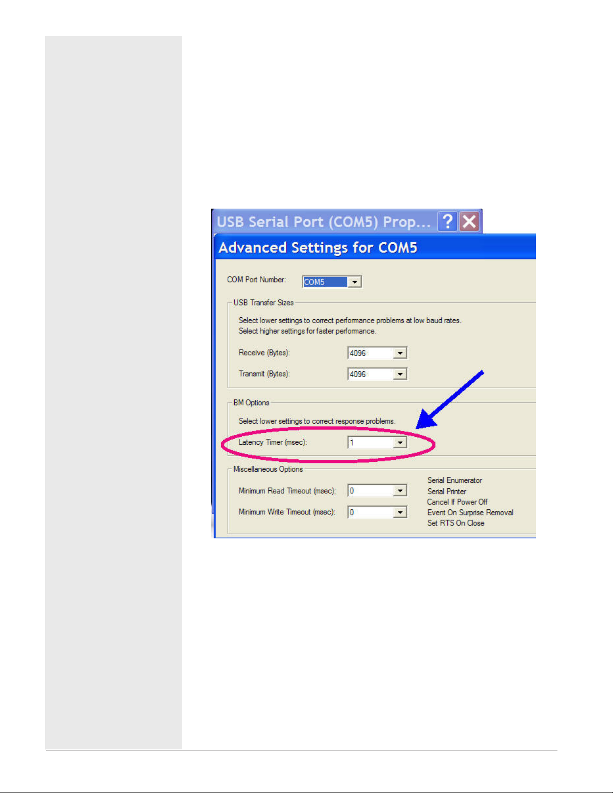
Note:
When connecting the USB converter to the PC it is suggested that the Latency
Timer be changed from the default of 16 msec to 1 msec. Failure to make this
change may cause communication loss between the PC running ZE-ZONE Configurator software and the control.
To modify Latency Timer settings follow the steps below:
1. Navigate to Device Manager.
2. Double click on Ports.
3. Right click on the USB serial port in use and select Properties.
4. Click the tab labeled Port settings and then click the Advance button.
Warning: ç
Explosion Hazard – Substitution of
component may impair suitability for
CLASS I, DIVISION 2.
Warning: ç
Explosion Hazard - Do not disconnect
while the circuit is live or unless the
area is known to be free of ignitable
concentrations of flammable substances.
Watlow EZ-ZONE® RME Module • 26 • Chapter 2 Install and Wire
Page 30
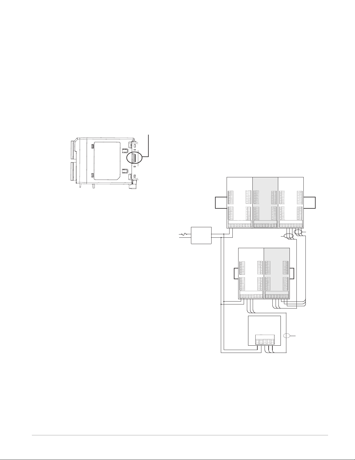
Connecting and Wiring the Modules
RM System Connections
Components of a RM system can be installed as
stand-alone modules or can be interconnected on
the DIN rail as shown below. When modules are
connected together, power and communications are
shared between modules over the modular backplane interconnection. Therefore, bringing the necessary power and communications wiring to any
one connector in slot C is sufficient. The modular
backplane interconnect comes standard with every
module ordered and is generic in nature, meaning
any of the RM modules shown below on the DIN
rail can use it.
Modular backplane interconnect
Notice in the split rail system diagram that
a single power supply is being used across both
DIN rails. One notable consideration when designing the hardware layout would be the available power supplied and the loading affect of all
of the modules used. Watlow provides three options for power supplies listed below:
1. 90-264 Vac to 24Vdc @ 31 watts (Part #:
0847-0299-0000)
2. 90-264 Vac to 24Vdc @ 60 watts (Part #:
0847-0300-0000)
3. 90-264 Vac to 24Vdc @ 91 watts (Part #:
0847-0301-0000)
With regards to the modular loading affect, maximum power for each is listed below:
1. RMCxxxxxxxxxxxx @ 7 watts
2. RMEx-xxxx-xxxx @ 7 watts
3. RMAx-xxxx-xxxx @ 4 watts
So, in the split rail system diagram, the maximum current draw on the supply would be 38
Watts.
- 2 RMC modules consumes 14W
- 2 RME modules consumes 14W
- 1 RMA module consumes 4W
- 1 Remote User Interface consumes 6W
With this power requirement the second or third
power supply could be used.
Another hardware configuration scenario
that could present itself (graphic not shown)
would be a configuration that requires more than
one supply. Lets make some assumptions per-
taining to the split rail system diagram shown below.
The power supply used is the 91W supply. The top DIN
rail now has the following modules:
- 2 RMC modules consumes 14W
- 1 RMA consumes 4W
- 11 RME modules consumes 77W
As can now be seen, the total power requirement exceeds 91W. In this case, another power supply would
be required. To incorporate another supply in this system simply disconnect pins 99 and 98 on the remote
DIN rail and connect another appropriately sized power supply to those same pins.
When using a split rail configuration ensure that
the interconnections for the Inter-module Bus and
Standard Bus do not exceed 200 feet. Standard Bus
and the Inter-module Buses are different protocols
and both are required for split rail configurations.
Without having both connected communications between modules would not be possible.
RM Access
Module
Slot D
_
_
_
_
_
_
_
_
Slot A
_
_
_
_
_
_
_
_
98
Standard Bus
Address 3
Slot C
CD
CF
99
Slot E
_
_
_
_
_
_
_
_
Slot B
_
_
_
_
_
_
_
_
CX
CE
CY
CZ
Inter-module
Bus
Slot E
_
_
_
_
_
_
_
_
Slot B
_
_
_
_
_
_
_
_
CX
CE
CY
CZ
Low Voltage
Class 2
Power Supply
RM Controller
Module
RMCxxxxxxxxxAxx
Slot D
Slot A
_
_
_
_
_
_
_
_
_
_
_
_
_
_
_
_
99
98
Standard Bus
Address 1
Slot C
CD
CE
CF
Slot E
_
_
_
_
_
_
_
_
Slot B
_
_
_
_
_
_
_
_
CX
CZ
RM Expansion
Module
RMEx-xxxx-xxxx RMAx-xxxx-xxxx
Slot D
_
_
_
Standard Bus
_
_
Address 2
_
_
_
Slot A
_
_
_
_
_
_
_
_
Slot C
CD
CF
CY
99
98
Standard Bus
Split Rail Conguration
RM Controller
Module
RMCxxxxxxxxxAxx
Slot D
_
_
_
Standard Bus
_
_
Address 4
_
_
_
Slot A
_
_
_
_
_
_
_
_
CF
99
98
RM Expansion
Module
RMEx-xxxx-xxxx
Slot E
Slot D
_
_
_
_
_
_
Standard Bus
_
_
_
_
Address 5
_
_
_
_
_
_
Slot A
Slot B
_
_
_
_
_
_
_
_
_
_
_
_
_
_
_
Slot C
_
CD
CX
CE
CY
CZ
99
98
RUI
EZKB-_ A _ _- _ _ _ _
CD
CE
CF
98
99
Slot E
_
_
_
_
_
_
_
_
Slot B
_
_
_
_
_
_
_
_
Slot C
CD
CX
CE
CY
CZ
CF
Standard Bus
Note:
Module is not provided with a disconnect, use of an
external disconnect is required. It should be located in
close proximity to the module and be labeled as the disconnect for the module.
Note:
Connecting power supplies in parallel is not allowed.
When power consumption is greater than 91 watts use a
split rail configuration.
Watlow EZ-ZONE® RME Module • 27 • Chapter 2 Install and Wire
Page 31

Wiring a Serial EIA-485 Network
Do not route network wires with power wires. Connect network wires in daisy-chain fashion when connecting multiple devices in a network.
A termination resistor may be required. Place a
A network using Watlow's Standard Bus and an RUI/Gateway.
120 Ω resistor across T+/R+ and T-/R- of the last controller on a on a network.
Note:
Termination resistors when used, require a termination resistor at both ends of the network.
EZ-ZONE ST
ST_ _ - (B or F) _ M _ -_ _ _ _
CD
CE
D6
D5
CF
B5
+ B
- A
98
99
power
common
power
EZ-ZONE PM
RUI/Gateway
EZKB-_ A _ _- _ _ _ _
CF
CD
CE
D6
D5
98
99
CF
CD
CE
98
99
B5
power
com
- A
+ B
power
common
- A
+ B
Power
Supply
fuse
EZ-ZONE RM
t
C
l
o
S
98 99 CF CD CE CZ CX CY
power
common
- A
+ B
Watlow EZ-ZONE® RME Module • 28 • Chapter 2 Install and Wire
Page 32

Conventions Used in the Menu Pages
To better understand the menu pages that follow
review the naming conventions used. When encountered throughout this document, the word "default"
implies as shipped from the factory. Each page (Operations, Setup and Factory) and their associated
menus have identical headers defined below:
Display
When the RME module is used in conjunction with
the RUI (optional equipment) visual information from
the control is displayed to the observer using a fairly
standard 7 segment display. Due to the use of this
technology, several characters displayed need some
interpretation, see the list below:
Note:
The communications protocols and associated addressing mentioned below and found in the menus are
available only when another module equipped with
the protocol is used in conjunction with the RME. The
RME module by itself has Watlow's Standard Bus
only.
Header Name Definition
Display
Parameter Name
Visually displayed information from the control.
Describes the function of
the given parameter.
Defines options available
for this prompt, i.e., min/
Range
max values (numerical),
yes/no, etc... (further explanation below).
Default
Values as delivered from
the factory.
Identifies unique parameModbus Relative Address
ters using either the Mod-
bus RTU or Modbus TCP
protocols.
Identifies unique param-
CIP (Common Industrial Protocol)
eters using either the De-
viceNet or EtherNet/IP
protocol (further explana-
tion below).
Identifies unique param-
Profibus Index
eters using Profibus DP
protocol (further explana-
tion below).
Identifies unique paramParameter ID
eters used with other soft-
ware such as, LabVIEW.
uint = Unsigned 16 bit
integer
dint = Signed 32-bit,
long
string = ASCII (8 bits
Data Type R/W
per character)
float = IEEE 754 32-bit
RWES = Readable
Writable
EEPROM (saved)
User Set (saved)
[1] = 1 [0] = 0 [i] = i [r] = r
[2] = 2 [a] = A [j ] = J [s] = S
[3] = 3 [h] = b [ h] = K [ t] = t
[4] = 4 [r] , [C] = c [l] = L [U] = u
[5] = 5 [d ] = d [ m] = M [u] = v
[6] = 6 [e] = E [n] = n [w ] = W
[7] = 7 [f] = F [o] = o [y ] = y
[8] = 8 [g ] = g [ p ] = P [2] = Z
[9] = 9 [h] = h [q ] = q
Range
Within this column notice that on occasion there will
be numbers found within parenthesis. This number
represents the enumerated value for that particular
selection. Range selections can be made simply by
writing the enumerated value of choice using any of
the available communications protocols. As an example, turn to the RME Setup Page and look at the
Alarm Menu and then the Alarm Type. To turn the
alarm off using Modbus simply write the value of 62
(off ) to register 401469 and send that value to the
control.
Communication Protocols
All modules come with the standard offering of Watlow's Standard Bus protocol used primarily for intermodule communications as well as for configuration
using EZ-ZONE Configurator software (free download from Watlow's web site (http://www.watlow.com).
The RM Access (RMA) module and the RUI can serve
as a gateway and have options for several different
protocols listed below:
- Modbus RTU 232/485
- EtherNet/IP, Modbus TCP
- DeviceNet
- Profibus DP
To learn more about the RMA or RUI modules click
on the link below. Once there simply type in RM in
the Keyword field.
http://www.watlow.com/ literature/manuals.cfm
Watlow EZ-ZONE® RME Module • 29 • Chapter 2 Install and Wire
Page 33

3
Chapter 3: Operations Pages
Operation Page Parameters
To navigate to the Operations Page using the RUI, follow the steps below:
1. From the Home Page, press both the Up ¿ and
Down ¯ keys for three seconds. [``Ai] will appear
in the upper display and [oPEr] will appear in the
lo wer displ ay.
2. Press the Up ¿ or Down ¯ key to view available
menus.
3. Press the Advance Key ‰ to enter the menu of
choice.
4. If a submenu exists (more than one instance), press
Note:
Some of these menus and parameters may not appear, depending on the controller's options. See model number
information in the Appendix for more information. If there is only one instance of a menu, no submenus will appear.
Note:
Some of the listed parameters may not be visible. Parameter visibility is dependent upon controller part number.
the Up ¿ or Down ¯ key to select and then press
the Advance Key ‰ to enter.
5. Press the Up ¿ or Down ¯ key to move through
available menu prompts.
6. Press the Infinity Key ˆ to move backwards
through the levels: parameter to submenu; submenu
to menu; menu to Home Page.
7. Press and hold the Infinity Key ˆ for two seconds to
return to the Home Page.
On the following pages, top level menus are identified
with a yellow background color.
[`dio]
[oPEr] Digital Input/Output Menu
[```1]
[`dio] Digital Input/Output (1 to 24)
[`do;S] Output State
[`di;S] Input State
[`ACt]
[oPEr] Action Menu
[```1]
[`ACt] Action (1 to 8)
[`Ei;S] Event Status
[ALM]
[oPEr] Alarm Menu
[```1]
[ALM] Alarm (1 to 8)
[`A;Lo] Low Set Point
[`A;hi] High Set Point
[a;Clr] Clear Request
[a;sir] Silence Request
[`a;st] State
[CUrr]
[oPEr] Current Menu
[```1]
[CUrr] Current (1 to 4)
[`C;hi] High Set Point
[`C;Lo] Low Set Point
[`CU;r] RMS Read
[`C;Er] Error
[`h;Er] Heater Error
[`Lnr]
[oPEr] Linearization Menu
[```1]
[`Lnr] Linearization (1 to 8)
[`Su;A] Source Value A
[oFSt] Offset
[``o;u] Output Value
[`CPE]
[oPEr] Compare Menu
[```1]
[`CPE] Compare (1 to 8)
[`Su;A] Source Value A
[`Su;b] Source Value B
[``o;u] Output Value
[tMr]
[oPEr] Timer Menu
[```1]
[tMr] Timer (1 to 8)
[`Su;A] Source Value A
[`Su;b] Source Value B
[``E;t] Elapsed Time
[``o;u] Output Value
[`Ctr]
[oPEr] Counter Menu
[```1]
[`Ctr] Counter (1 to 8)
[`Cnt] Count
[`Su;A] Source Value A
[`Su;b] Source Value B
[``o;u] Output Value
[`LgC]
[oPEr] Logic Menu
[```1]
[`LgC] Logic (1 to 8)
[`Su;A] Source Value A
[`Su;b] Source Value B
[`Su;C] Source Value C
[`Su;d] Source Value D
[`Su;E] Source Value E
[`Su;F] Source Value F
[`Su;g] Source Value G
[`Su;h] Source Value H
[``o;u] Output Value
[MAt]
[oPEr] Math Menu
[```1]
[MAt] Math (1 to 8)
[`Su;A] Source Value A
[`Su;b] Source Value B
[`Su;C] Source Value C
[`Su;d] Source Value D
[`Su;E] Source Value E
[``o;u] Output Value
[oFSt] Offset
[`SoF]
[oPEr] Special Output Function Menu
[```1]
[`SoF] Special Output Function (1 to 4)
[`Su;A] Source Value A
[`Su;b] Source Value B
[`ou;1] Output Value 1
[`ou;2] Output Value 2
[`ou;3] Output Value 3
[`ou;4] Output Value 4
Watlow EZ-ZONE® RME Module • 30 • Chapter 3 Operations Page
Page 34

RME Module • Operations Page
Display
Parameter Name
Description
[`dio]
[oPEr]
Digital Input / Output Menu
[`do;S]
[ do.S]
Digital Output (1 to 24)
Output State
View the state of this
output.
[`di;S]
[ di.S]
Digital Input (1 to 24)
Input State
View this event input
state.
No Display
Digital Input (1 to 24)
Source Error
View reported cause for
input malfunction.
[`ACt]
[oPEr]
Action Menu
[`Ei;S]
[ Ei.S]
Action (1 to 8)
Event Status
View this input state.
[ALM]
[oPEr]
Alarm Menu
[`A;Lo]
[ A.Lo]
Alarm (1 to 8)
Low Set Point
If Alarm Type (Setup
Page, Alarm Menu) is
set to:
process - set the process
value that will trigger a
low alarm.
Range Default
[`off] Off (62)
[``on] On (63)
[`off] Off (62)
[``on] On (63)
None (61)
Open (65)
Shorted (127)
Measurement error (140)
Bad calibration data (139)
Ambient error (9)
RTD error (14)
Fail (32)
Math error (1423)
Not sourced (246)
Stale (1617)
[`off] Off (62)
[``on] On (63)
-1,999.000 to 9,999.000°F
or units
-1,128.000 to 5,537.000°C
- - - - 372
- - - - 380
- - - - 388
- - - -
32.0°F
or units
0.0°C
Modbus
Relative
Address
[off 30]
[off 30]
[offset 30]
1288
[off 20]
1442
[off 60]
CIP
Class
Instance
Attribute
hex (dec)
0x6A (106)
1 to 18 (24)
7
0x6A (106)
1 to 18 (24)
0xB (11)
0x6A
(106)
1 to 18
(24)
0x0F (15)
0x6E (110)
1 to 8
5
0x6D
(109)
1 to 8
2
Profibus
Index
Param-
eter
ID
28 6007 uint
- - - - 6011 uint
- - - - 6015 uint
74 10005 uint
0 9002 float
Data
Type
&
Read/
Write
R
R
R
R
RWES
[`A;hi]
[ A.hi]
Alarm (1 to 8)
High Set Point
If Alarm Type (Setup
Page, Alarm Menu) is
-1,999.000 to 9,999.000°F
or units
-1,128.000 to 5,537.000°C
300.0°F
or units
150.0°C
1440
[off 60]
0x6D
(109)
1 to 8
1
1 9001 float
RWES
set to:
process - set the process
value that will trigger a
high alarm.
[a;Clr]
[A.CLr]
Alarm (1 to 8)
Alarm Clear Request
Write to this register to
clear an alarm
Note:
Some values will be rounded off to fit in the four-character display. Full values can be
read with other interfaces.
Note:
If there is only one instance of a menu, no submenus will appear.
0 None 1464
[offset 60]
0x6D
(109)
1 to 8
0xD (13)
14 9013
uint
W
R: Read
W: Write
E: EEPROM
S: User
Set
** These parameters/prompts are available in these menus with firmware revisions 6.0 and
above.
Watlow EZ-ZONE® RME Module • 31 • Chapter 3 Operations Page
Page 35

RME Module • Operations Page
Display
[A;sir]
[A.Sir]
Parameter Name
Description
Alarm (1 to 4)
Alarm Silence Request
Range Default
0 None 1466
Write to this register to
silence an alarm
[`a;st]
[ A.St]
Alarm (1 to 8)
Alarm State
View state of alarm
Startup (88)
None (61)
Blocked (12)
None 1456
Alarm low (8)
Alarm high (7)
Error (28)
No Display
Alarm (1 to 4)
Alarm Clearable
[``no] No (59)
[`YES] Yes (106)
None 1462
Read to determine if
alarm can be cleared.
No Display
Alarm (1 to 8)
Silenced
Yes (106)
No (59)
- - - - 1460
Read to see if alarm is active but has been silenced
by Alarm Silence Request.
No Display
Alarm (1 to 8)
Latched
Yes (106)
No (59)
- - - - 1458
Read to see if alarm is
currently latched.
[CUrr]]
[oPEr]]
Current Menu
[`C;hi]
[ C.hi]
Current (1 to 4)
High Set Point
-1,999.000 to 9,999.000 50.0 1094
Set the current value that
will trigger a high heater
error state.
[`C;Lo]
[ C.Lo]
Current (1 to 4)
Low Set Point
-1,999.000 to 9,999.000 0.0 1096
Set the current value that
will trigger a low heater
error state.
[`CU;r]
[ CU.r]
Sensed Current (1 to 4)
Read
-1,999.000 to 9,999.000 - - - - 1080
View the most recent current value monitored by
the current transformer.
[`C;Er]
[ C.Er]
[`h;Er]
[ h.Er]
Current (1 to 4)
Error
View the cause of the
most recent load fault.
Current (1 to 4)
Heater Error
View the cause of the
most recent load fault
[nonE] None (61)
[Shrt] Shorted (127)
[open] Open (65)
[nonE] None (61)
[high] High (37)
[Low] Low (53)
- - - - 1082
- - - - 1084
monitored by the current
transformer.
Note:
Some values will be rounded off to fit in the four-character display. Full values can be
read with other interfaces.
Note:
If there is only one instance of a menu, no submenus will appear.
** These parameters/prompts are available in these menus with firmware revisions 6.0 and
above.
Modbus
Relative
Address
[offset 60]
CIP
Class
Instance
Attribute
hex (dec)
0x6D
(109)
Profibus
Index
15 9014
Param-
eter
ID
Data
Type
Read/
Write
uint
W
1 to 8
0xE (14)
[offset 60]
0x6D
(109)
- - - - 9009
uint
R
1 to 8
9
[offset 60]
0x6D
(109)
- - - - 9012
uint
R
1 to 8
0xC (12)
[offset 60]
0x6D
(109)
- - - - 9011 uint
R
1 to 4
0x0B (11)
[offset 60]
0x6D
(109)
- - - - 9010 uint
R
1 to 4
0x0A (10)
Note: To use the current sensing feature, Time Base (Setup
Page, Output Menu) must be set to 0.7 seconds or more.
[offset 50]
0x73
(115)
- - - - 15008 float
RWES
1 to 4
8
[offset 50]
0x73
(115)
- - - - 15009 float
RWES
1 to 4
9
[offset 50]
0x73
(115)
- - - - 15001 float
R
1 to 4
1
[offset 50]
0x73
(115)
- - - - 15002 uint
R
1 to 4
2
[offset 50]
0x73
(115)
- - - - 15003 uint
R
1 to 4
3
R: Read
W: Write
E: EEPROM
S: User
Set
&
Watlow EZ-ZONE® RME Module • 32 • Chapter 3 Operations Page
Page 36

RME Module • Operations Page
Display
No Display
Parameter Name
Description
Current (1 to 4)
Actual Power
Power delivered to output
monitored by CT.
No Display
Current (1 to 4)
Error Status
View the cause of the
most recent load fault
[`Lnr]
[oPEr]
Linearization Menu
[`Su;A]
[ Su.A]
Linearization (1 to 8)
Source Value A
View the value of Source
A.
[oFSt]
[oFSt]
Linearization (1 to 8)
Offset
Set an offset to be applied
to this function's output.
[``o;u]
[ o.v]
Linearization (1 to 8)
Output Value
View the value of this
function's output.
No Display
Linearization (1 to 8)
Error
Read reported cause for
linearization error.
[`CPE]
[oPEr]
Compare Menu
[`Su;A]
[ Su.A]
Compare (1 to 8)
Source Value A
View the value of Source
A.
Range Default
Relative
Address
0.0 to 100.0% - - - - 1118
[offset 50]
Modbus
None (61)
Fail (32)
-1,999.000 to 9,999.000°F
or units
- - - - 1120
[offset 50]
- - - - 5546
[off 70]
-1,128.000 to 5,537.000°C
-1,999.000 to 9,999.000°F
or units
0 5550
[off 70]
-1,128.000 to 5,537.000°C
-1,999.000 to 9,999.000°F
or units
- - - - 5552
[off 70]
-1,128.000 to 5,537.000°C
None (61)
Open (65)
- - - - 5594
[offset 70]
Shorted (127)
Measurement error (140)
Bad calibration data (139)
Ambient error (9)
RTD error (14)
Fail (32)
Math error (1423)
Not sourced (246)
Stale (1617)
Can't process (1659)
-1,999.000 to 9,999.000°F
or units
- - - - 3992
[off 40]
-1,128.000 to 5,537.000°C
CIP
Class
Instance
Attribute
hex (dec)
0x73
(115)
1 to 4
0x14 (20)
0x73
(115)
1 to 4
21
0x86
(134)
1 to 8
4
0x86
(134)
1 to 8
6
0x86
(134)
1 to 8
7
0x86
(134)
1 to 8
0x1C (28)
0x80
(128)
1 to 8
7
Profibus
Index
Param-
eter
ID
- - - - 15020 float
- - - - 15021 uint
- - - - 34004 float
- - - - 34006 float
- - - - 34007 float
- - - - 34028 uint
- - - - 28007 float
Data
Type
&
Read/
Write
R
R
R
RWES
R
R
R
[`Su;b]
[ Su.b]
Compare (1 to 8)
Source Value B
View the value of Source
B.
[``o;u]
[ o.v]
Compare (1 to 8)
Output Value
View the value of this
function's output.
Note:
Some values will be rounded off to fit in the four-character display. Full values can be
read with other interfaces.
Note:
If there is only one instance of a menu, no submenus will appear.
-1,999.000 to 9,999.000°F
or units
-1,128.000 to 5,537.000°C
[`off] Off (62)
[``on] On (63)
- - - - 3994
[off 40]
- - - - 3998
[off 40]
0x80
(128)
1 to 8
8
0x80
(128)
1 to 8
0xA (10)
- - - - 28008 float
R
- - - - 28010 uint
R
R: Read
W: Write
E: EEPROM
S: User
Set
** These parameters/prompts are available in these menus with firmware revisions 6.0 and
above.
Watlow EZ-ZONE® RME Module • 33 • Chapter 3 Operations Page
Page 37

RME Module • Operations Page
Display
No Display
Parameter Name
Description
Compare (1 to 8)
Error
Read reported cause for
compare error
Range Default
None (61)
Open (65)
Shorted (127)
Measurement error (140)
- - - - 4004
Bad Cal Data (139)
Ambient Error (9)
RTD Error (141)
Fail (32)
Math Error (1423)
Not Sourced (246)
Stale (1617)
[tMr]
[oPEr]
Timer Menu
[`Su;A]
[ Su.A]
Timer (1 to 8)
Source Value A
View the value of Source
[`off] Off (62)
[``on] On (63)
- - - - 4952
A.
[`Su;b]
[ Su.b]
Timer (1 to 8)
Source Value B
View the value of Source
[`off] Off (62)
[``on] On (63)
- - - - 4954
B.
[``E;t]
[ E.t]
Timer (1 to 8)
Elapsed Time
0.0 to 30,000.000 seconds - - - - 4970
View the value of this
function's elapsed time.
[``o;u]
[ o.v]
Timer (1 to 8)
Output Value
View the value of this
[`off] Off (62)
[``on] On (63)
- - - - 4958
function's output.
No Display
Timer (1 to 8)
Error
Read reported cause for
timer error
None (61)
Open (65)
Shorted (127)
Measurement error (140)
- - - - 4974
Bad Cal Data (139)
Ambient Error (9)
RTD Error (141)
Fail (32)
Math Error (1423)
Not Sourced (246)
Stale (1617)
[`Ctr]
[oPEr]
Counter Menu
[`Cnt]
[ Cnt]
Counter (1 to 8)
Count
0 to 9,999 - - - - 4488
View the function's total
count.
Note:
Some values will be rounded off to fit in the four-character display. Full values can be
read with other interfaces.
Note:
If there is only one instance of a menu, no submenus will appear.
** These parameters/prompts are available in these menus with firmware revisions 6.0 and
above.
Modbus
Relative
Address
[offset 40]
[off 50]
[off 50]
[off 50]
[off 50]
[offset 50]
[off 40]
CIP
Class
Instance
Attribute
hex (dec)
0x80
(128)
1 to 8
0x0D (13)
0x83
(131)
1 to 8
7
0x83
(131)
1 to 8
8
0x83
(131)
1 to 8
0x10 (16)
0x83
(131)
1 to 8
0xA (10)
0x83
(131)
1 to 8
0x12 (18)
0x82
(130)
1 to 8
0xF (15)
Profibus
Index
Param-
eter
ID
- - - - 28013 uint
- - - - 31007 uint
- - - - 31008 uint
- - - - 31016 float
- - - - 31010 uint
- - - - 31018 uint
143 30015 uint
Data
Type
&
Read/
Write
R
R
R
R
R
R
R
R: Read
W: Write
E: EEPROM
S: User
Set
Watlow EZ-ZONE® RME Module • 34 • Chapter 3 Operations Page
Page 38

RME Module • Operations Page
Display
[`Su;A]
[ Su.A]
Parameter Name
Description
Counter (1 to 8)
Source Value A
View the value of Source
Range Default
[`off] Off (62)
[``on] On (63)
- - - - 4472
A.
[`Su;b]
[ Su.b]
Counter (1 to 8)
Source Value B
View the value of Source
[`off] Off (62)
[``on] On (63)
- - - - 4474
B.
[``o;u]
[ o.v]
Counter (1 to 8)
Output Value
View the value of this
[`off] Off (62)
[``on] On (63)
- - - - 4478
function's output.
No Display
Counter (1 to 8)
Error
Read reported cause for
counter error
None (61)
Open (65)
Shorted (127)
Measurement error (140)
- - - - 4490
Bad Cal Data (139)
Ambient Error (9)
RTD Error (141)
Fail (32)
Math Error (1423)
Not Sourced (246)
Stale (1617)
[`LgC]
[oPEr]
Logic Menu
[`Su;A]
[ Su.A]
Logic (1 to 8)
Source Value A
View the value of Source
[`off] Off (62)
[``on] On (63)
- - - - 3068
A.
[`Su;b]
[ Su.b]
Logic (1 to 8)
Source Value B
View the value of Source
[`off] Off (62)
[``on] On (63)
- - - - 3070
B.
[`Su;C]
[ Su.C]
Logic (1 to 8)
Source Value C
View the value of Source
[`off] Off (62)
[``on] On (63)
- - - - 3072
C.
[`Su;d]
[ Su.d]
Logic (1 to 8)
Source Value D
View the value of Source
[`off] Off (62)
[``on] On (63)
- - - - 3074
D.
[`Su;E]
[ Su.E]
Logic (1 to 8)
Source Value E
View the value of Source
[`off] Off (62)
[``on] On (63)
- - - - 3076
E.
[`Su;F]
[ Su.F]
Logic (1 to 8)
Source Value F
View the value of Source
[`off] Off (62)
[``on] On (63)
- - - - 3078
F.
Note:
Some values will be rounded off to fit in the four-character display. Full values can be
read with other interfaces.
Note:
If there is only one instance of a menu, no submenus will appear.
** These parameters/prompts are available in these menus with firmware revisions 6.0 and
above.
Modbus
Relative
Address
[off 40]
[off 40]
[off 40]
[offset 40]
[off 80]
[off 80]
[off 80]
[off 80]
[off 80]
[off 80]
CIP
Class
Instance
Attribute
hex (dec)
0x82
(130)
1 to 8
7
0x82
(130)
1 to 8
8
0x82
(130)
1 to 8
0xA (10)
0x82
(130)
1 to 8
0x10 (16)
0x7F
(127)
1 to 8
0x19 (25)
0x7F
(127)
1 to 8
0x1A (26)
0x7F
(127)
1 to 8
0x1B (27)
0x7F
(127)
1 to 8
0x1C (28)
0x7F
(127)
1 to 8
0x1D (29)
0x7F
(127)
1 to 8
0x1E (30)
Profibus
Index
Param-
eter
ID
- - - - 30007 uint
- - - - 30008 uint
- - - - 30010 uint
- - - - 30016 uint
- - - - 27025 uint
- - - - 27026 uint
- - - - 27027 uint
- - - - 27028 uint
- - - - 27029 uint
- - - - 27030 uint
Data
Type
&
Read/
Write
R
R
R
R
R
R
R
R
R
R
R: Read
W: Write
E: EEPROM
S: User
Set
Watlow EZ-ZONE® RME Module • 35 • Chapter 3 Operations Page
Page 39

RME Module • Operations Page
Display
[`Su;g]
[ Su.g]
Parameter Name
Description
Logic (1 to 8)
Source Value G
View the value of Source
Range Default
[`off] Off (62)
[``on] On (63)
- - - - 3080
G.
[`Su;h]
[ Su.h]
Logic (1 to 8)
Source Value H
View the value of Source
[`off] Off (62)
[``on] On (63)
- - - - 3082
H.
[``o;u]
[ o.v]
Logic (1 to 8)
Output Value
View the value of this
[`off] Off (62)
[``on] On (63)
- - - - 3086
function's output.
No Display
Logic (1 to 8)
Error
Read reported cause for
logic error
None (61)
Open (65)
Shorted (127)
Measurement error (140)
- - - - 3090
Bad Cal Data (139)
Ambient Error (9)
RTD Error (141)
Fail (32)
Math Error (1423)
Not Sourced (246)
Stale (1617)
[MAt]
[oPEr]
Math Menu
[`Su;A]
[ Su.A]
Math (1 to 8)
Source Value A
View the value of Source
-1,999.000 to 9,999.000°F
or units
-1,128.000 to 5,537.000°C
- - - - 2210
A.
[`Su;b]
[ Su.b]
Math (1 to 8)
Source Value B
View the value of Source
-1,999.000 to 9,999.000°F
or units
-1,128.000 to 5,537.000°C
- - - - 2212
B.
[`Su;C]
[ Su.C]
Math (1 to 8)
Source Value C
View the value of Source
-1,999.000 to 9,999.000°F
or units
-1,128.000 to 5,537.000°C
- - - - 2214
C.
[`Su;d]
[ Su.d]
Math (1 to 8)
Source Value D
View the value of Source
-1,999.000 to 9,999.000°F
or units
-1,128.000 to 5,537.000°C
- - - - 2216
D.
[`Su;E]
[ Su.E]
Math (1 to 8)
Source Value E
View the value of Source
[`off] Off (62)
[``on] On (63)
- - - - 2218
E.
[oFSt]
[oFSt]
Math (1 to 8)
Offset
Set an offset to be applied
-1,999.000 to 9,999.000°F
or units
-1,128.000 to 5,537.000°C
0 2224
to this function's output.
Note:
Some values will be rounded off to fit in the four-character display. Full values can be
read with other interfaces.
Note:
If there is only one instance of a menu, no submenus will appear.
** These parameters/prompts are available in these menus with firmware revisions 6.0 and
above.
Modbus
Relative
Address
[off 80]
[off 80]
[off 80]
[offset 80]
[off 70]
[off 70]
[off 70]
[off 70]
[off 70]
[off 70]
CIP
Class
Instance
Attribute
hex (dec)
0x7F
(127)
1 to 8
0x1F (31)
0x7F
(127)
1 to 8
0x20 (32)
0x7F
(127)
1 to 8
0x22 (34)
0x7F
(127)
1 to 4
0x24 (36)
0x7D
(125)
1 to 8
0x10 (16)
0x7D
(125)
1 to 8
0x11 (17)
0x7D
(125)
1 to 8
0x12 (18)
0x7D
(125)
1 to 8
0x13 (19)
0x7D
(125)
1 to 8
0x14 (20)
0x7D
(125)
1 to 8
0x17 (23)
Profibus
Index
Param-
eter
ID
- - - - 27031 uint
- - - - 27032 uint
- - - - 27034 uint
- - - - 27036 uint
- - - - 25016 float
- - - - 25017 float
- - - - 25018 float
- - - - 25019 float
- - - - 25020 uint
- - - - 25023 float
Data
Type
&
Read/
Write
R
R
R
R
R
R
R
R
R
RWES
R: Read
W: Write
E: EEPROM
S: User
Set
Watlow EZ-ZONE® RME Module • 36 • Chapter 3 Operations Page
Page 40

RME Module • Operations Page
Display
[``o;u]
[ o.v]
Parameter Name
Description
Math (1 to 8)
Output Value
View the value of this
Range Default
-1,999.000 to 9,999.000°F
or units
-1,128.000 to 5,537.000°C
- - - - 2222
function's output.
No Display
Math (1 to 8)
Error
Read reported cause for
math error.
None (61)
Open (65)
Shorted (127)
Measurement error (140)
- - - - 2236
Bad Cal Data (139)
Ambient Error (9)
RTD Error (141)
Fail (32)
Math Error (1423)
Not Sourced (246)
Stale (1617)
[`SoF]
[oPEr]
Special Output Function Menu
[`Su;A]
[ Su.A]
Special Output Function
(1 to 4)
Source Value A
-1,999.000 to 9,999.000°F
or units
-1,128.000 to 5,537.000°C
- - - - 6632
View the value of Source
A.
[`Su;b]
[ Su.b]
Special Output Function
(1 to 4)
Source Value B
-1,999.000 to 9,999.000°F
or units
-1,128.000 to 5,537.000°C
- - - - 6634
View the value of Source
B.
[`o;u1]
[ o.v1]
Special Output Function
(1 to 4)
Output Value 1
-1,999.000 to 9,999.000°F
or units
-1,128.000 to 5,537.000°C
- - - - 6638
View the value of this
function's Output 1.
No Display
Special Output Function
(1 to 4)
Error 1
Read reported cause for
output error.
None (61)
Open (65)
Shorted (127)
Measurement error (140)
Bad calibration data (139)
- - - - 6640
Ambient error (9)
RTD error (14)
Fail (32)
Math error (1423)
Not sourced (246)
Stale (1617)
Can't process (1659)
[`o;u2]
[ o.v2]
Special Output Function
(1 to 4)
Output Value 2
-1,999.000 to 9,999.000°F
or units
-1,128.000 to 5,537.000°C
- - - - 6642
View the value of this
function's Output 2.
Note:
Some values will be rounded off to fit in the four-character display. Full values can be
read with other interfaces.
Note:
If there is only one instance of a menu, no submenus will appear.
** These parameters/prompts are available in these menus with firmware revisions 6.0 and
above.
Modbus
Relative
Address
[off 70]
[offset 70]
[off 80]
[off 80]
[off 80]
[offset 80]
[off 80]
CIP
Class
Instance
Attribute
hex (dec)
0x7D
(125)
1 to 8
0x16 (22)
0x7D
(125)
1 to 8
0x1D (29)
0x87
(135)
1 to 4
7
0x87
(135)
1 to 4
8
0x87
(135)
1 to 4
0xA (10)
0x87
(135)
1 to 4
0x0B (11)
0x87
(135)
1 to 4
0xC (12)
Profibus
Index
Param-
eter
ID
- - - - 25022 float
- - - - 25029 uint
- - - - 35007 float
- - - - 35008 float
- - - - 35010 float
- - - - 35011 uint
- - - - 35012 float
Data
Type
&
Read/
Write
R
R
R
R
R
R
R
R: Read
W: Write
E: EEPROM
S: User
Set
Watlow EZ-ZONE® RME Module • 37 • Chapter 3 Operations Page
Page 41

RME Module • Operations Page
Display
No Display
Parameter Name
Description
Special Output Function
(1 to 4)
Error 2
Read reported cause for
output error.
Range Default
None (61)
Open (65)
Shorted (127)
Measurement error (140)
Bad calibration data (139)
- - - - 6644
Ambient error (9)
RTD error (14)
Fail (32)
Math error (1423)
Not sourced (246)
Stale (1617)
Can't process (1659)
[`o;u3]
[ o.v3]
Special Output Function
(1 to 4)
Output Value 3
-1,999.000 to 9,999.000°F
or units
-1,128.000 to 5,537.000°C
- - - - 6646
View the value of this
function's Output 3.
No Display
Special Output Function
(1 to 4)
Error 3
Read reported cause for
output error.
None (61)
Open (65)
Shorted (127)
Measurement error (140)
Bad calibration data (139)
- - - - 6648
Ambient error (9)
RTD error (14)
Fail (32)
Math error (1423)
Not sourced (246)
Stale (1617)
Can't process (1659)
[`o;u4]
[ o.v4]
Special Output Function
(1 to 4)
Output Value 4
-1,999.000 to 9,999.000°F
or units
-1,128.000 to 5,537.000°C
- - - - 6650
View the value of this
function's Output 4.
No Display
Special Output Function
(1 to 4)
Error 4
Read reported cause for
output error.
None (61)
Open (65)
Shorted (127)
Measurement error (140)
Bad calibration data (139)
- - - - 6652
Ambient error (9)
RTD error (14)
Fail (32)
Math error (1423)
Not sourced (246)
Stale (1617)
Can't process (1659)
Note:
Some values will be rounded off to fit in the four-character display. Full values can be
read with other interfaces.
Note:
If there is only one instance of a menu, no submenus will appear.
** These parameters/prompts are available in these menus with firmware revisions 6.0 and
above.
Modbus
Relative
Address
[offset 80]
[off 80]
[offset 80]
[off 80]
[offset 80]
CIP
Class
Instance
Attribute
hex (dec)
0x87
(135)
1 to 4
0x0D (13)
0x87
(135)
1 to 4
0xE (14)
0x87
(135)
1 to 4
0x0F (15)
0x87
(135)
1 to 4
0x10 (16)
0x87
(135)
1 to 4
0x11 (17)
Profibus
Index
Param-
eter
ID
- - - - 35013 uint
- - - - 35014 float
- - - - 35015 uint
- - - - 35016 float
- - - - 35017 uint
Data
Type
&
Read/
Write
R
R
R
R
R
R: Read
W: Write
E: EEPROM
S: User
Set
Watlow EZ-ZONE® RME Module • 38 • Chapter 3 Operations Page
Page 42

4
Chapter 4: Setup Pages
Setup Page Parameters
To navigate to the Setup Page using the RUI, follow
the steps below:
1. From the Home Page, press both the Up ¿ and
Down ¯ keys for six seconds. [``Ai] will appear
in the upper display and [`Set] will appear in the
lo wer displ ay.
Note:
If keys are released when [OPEr] is displayed, press
the Infinity Key ˆ or reset key to exit and repeat until [`Set] is displayed.
2. Press the Up ¿ or Down ¯ key to view available
menus.
3. Press the Advance Key ‰ to enter the menu of
choice.
Note:
Some of these menus and parameters may not appear, depending on the controller's options. See model number
information in the Appendix for more information. If there is only one instance of a menu, no submenus will appear.
Note:
Some of the listed parameters may not be visible. Parameter visibility is dependent upon controller part number.
4. If a submenu exists (more than one instance), press
the Up ¿ or Down ¯ key to select and then press
the Advance Key ‰ to enter.
5. Press the Up ¿ or Down ¯ key to move through
available menu prompts.
6. Press the Infinity Key ˆ to move backwards
through the levels: parameter to submenu; submenu
to menu; menu to Home Page.
7. Press and hold the Infinity Key ˆ for two seconds to
return to the Home Page.
On the following pages, top level menus are identified
with a yellow background color.
[`dio]
[`Set] Digital Input/Output Menu
[```1]
[`dio] Digital Input/Output (1 to 24)
[`dir] Direction
[``Fn] Function
[``Fi] Function Instance
[`S2;A] Source Zone A
[`o;Ct] Control
[`o;tb] Time Base
[`o;Lo] Low Power Scale
[`o;hi] High Power Scale
[`ACt]
[`Set] Action Menu
[```1]
[`ACt] Action (1 to 8)
[``Fn] Function
[``Fi] Function Instance
[SFn;A] Source Function A
[`Si;A] Source Instance A
[`S2;A] Source Zone A
[`LEu] Active Level
[otpt]
[`Set] Output Menu
[```1]
[otpt] Output (1 to 24)
[``Fn] Function
[``Fi] Function Instance
[`S2;A] Source Zone A
[`o;Ct] Control
[`o;tb] Time Base
[`o;Lo] Low Power Scale
[`o;hi] High Power Scale
[otpt] Output 1-3, 7-9, 13-15, 19-21
process
[`o;ty] Type
[``Fn] Function
[``Fi] Function Instance
[`S2;A] Source Zone A
[`S;Lo] Scale Low
[`S;hi] Scale High
[`r;Lo] Range Low
[`r;hi] Range High
[`o;CA] Calibration Offset
[ALM]
[`Set] Alarm Menu
[```1]
[ALM] Alarm (1 to 8)
[`A;ty] Type
[`Sr;A] Source
[`is;A] Source Instance
[`S2;A] Source Zone
[`A;hy] Hysteresis
[`a;Lg] Logic
[`A;SD] Sides
[`A;Lo] Low Set Point **
[`A;hi] High Set Point **
[`a;LA] Latching
[`A;bL] Blocking
[`a;Si] Silencing
[A;dsp] Display
[`A;dL] Delay Time
[a;Clr] Clear Request **
[a;sir] Silence Request **
[`a;st] State **
[CUrr]
[`Set] Current Menu
[```1]
[CUrr] Current 1 to 4
[`C;Sd] Sides
[`C;Ur] Read Enable
[`C;dt] Detection Threshold
[`C;SC] Input Current Scaling
[C;ofs] Heater Current Offset
[`C;Si] Output Source Instance
[`Lnr]
[`Set] Linearization Menu
[```1]
[`Lnr] Linearization (1 to 8)
[``Fn] Function
[SFn;A] Source Function A
[`Si;A] Source Instance A
[`S2;A] Source Zone A
[Unit] Units
[`ip;1] Input Point 1
[`op;1] Output Point 1
[`ip;2] Input Point 2
[`op;2] Output Point 2
[`ip;3] Input Point 3
[`op;3] Output Point 3
[`ip;4] Input Point 4
[`op;4] Output Point 4
[`ip;5] Input Point 5
[`op;5] Output Point 5
[`ip;6] Input Point 6
[`op;6] Output Point 6
[`ip;7] Input Point 7
[`op;7] Output Point 7
[`ip;8] Input Point 8
Watlow EZ-ZONE® RME Module • 39 • Chapter 4 Setup Page
Page 43

[`op;8] Output Point 8
[`ip;9] Input Point 9
[`op;9] Output Point 9
[ip;10] Input Point 10
[op;10] Output Point 10
[`CPE]
[`Set] Compare Menu
[```1]
[`CPE] Compare (1 to 8)
[``Fn] Function
[`toL] Tolerance
[SFn;A] Source Function A
[`Si;A] Source Instance A
[`S2;A] Source Zone A
[SFn;B] Source Function B
[`Si;b] Source Instance B
[`S2;b] Source Zone B
[`Er;h] Error Handling
[tMr]
[`Set] Timer Menu
[```1]
[tMr] Timer (1 to 8)
[``Fn] Function
[SFn;A] Source Function A
[`Si;A] Source Instance A
[`S2;A] Source Zone A
[SAS;A] Source Active State A
[SFn;B] Source Function B
[`Si;b] Source Instance B
[`S2;b] Source Zone B
[SAS;b] Source Active State B
[``ti] Time
[`LEu] Active Level
[`Ctr]
[`Set] Counter Menu
[```1]
[`Ctr] Counter (1 to 8)
[``fn] Function
[SFn;A] Source Function A
[`Si;A] Source Instance A
[`S2;A] Source Zone A
[SAS;A] Source Active State A
[SFn;B] Source Function B
[`Si;b] Source Instance B
[`S2;b] Source Zone B
[SAS;b] Source Active State B
[LoAd] Load Value
[trgt] Target Value
[`lat] Latching
[`LgC]
[`Set] Logic Menu
[```1]
[`LgC] Logic (1 to 8)
[``Fn] Function
[SFn;A] Source Function A
[`Si;A] Source Instance A
[`S2;A] Source Zone A
[SFn;B] Source Function B
[`Si;B] Source Instance B
[`S2;B] Source Zone B
[SFn;C] Source Function C
[`Si;C] Source Instance C
[`S2;C] Source Zone C
[SFn;D] Source Function D
[`Si;D] Source Instance D
[`S2;D] Source Zone D
[SFn;E] Source Function E
[`Si;E] Source Instance E
[`S2;E] Source Zone E
[SFn;F] Source Function F
[`Si;F] Source Instance F
[`S2;F] Source Zone F
[SFn;G] Source Function G
[`Si;G] Source Instance G
[`S2;G] Source Zone G
[SFn;H] Source Function H
[`Si;H] Source Instance H
[`S2;H] Source Zone H
[`Er;h] Error Handling
[MAt]
[`Set] Math Menu
[```1]
[MAt] Math (1 to 8)
[``Fn] Function
[SFn;A] Source Function A
[`Si;A] Source Instance A
[`S2;A] Source Zone A
[SFn;B] Source Function B
[`Si;B] Source Instance B
[`S2;B] Source Zone B
[SFn;C] Source Function C
[`Si;C] Source Instance C
[`S2;C] Source Zone C
[SFn;D] Source Function D
[`Si;D] Source Instance D
[`S2;D] Source Zone D
[SFn;E] Source Function E
[`Si;E] Source Instance E
[`S2;E] Source Zone E
[`S;Lo] Scale Low
[`S;hi] Scale High
[Unit] Units
[`r;Lo] Range Low
[`r;hi] Range High
[p;unt] Pressure Units
[a;unt] Altitude Units
[`FiL] Filter
[`SoF]
[`Set] Special Output Function Menu
[```1]
[`SoF] Special Output Function (1 to 4)
[``Fn] Function
[SFn;A] Source Function A
[`Si;A] Source Instance A
[`S2;A] Source Zone A
[SFn;B] Source Function B
[`Si;B] Source Instance B
[`S2;B] Source Zone B
[Pon;A] Power On Level 1
[PoF;A] Power Off Level 1
[Pon;b] Power On Level 2
[PoF;b] Power Off Level 2
[`on;t] On Time
[`of;t] Off Time
[``t;t] Valve Travel Time
[``db] Dead Band
[`os;1] Output 1 Size
[`os;2] Output 2 Size
[`os;3] Output 3 Size
[`os;4] Output 4 Size
[`t;dl] Time Delay
[`ot;o] Output Order
[`uAr]
[`Set] Variable Menu
[```1]
[`uAr] Variable (1 to 8)
[type] Data Type
[Unit] Units
[`dig] Digital
[AnLg] Analog
[gLbL]
[`Set] Global Menu
[`C_F] Display Units
[AC;LF] AC Line Frequency
[d;prs] Display Pairs
[Usr;s] User Settings Save
[Usr;r] User Settings Restore
Watlow EZ-ZONE® RME Module • 40 • Chapter 4 Setup Page
Page 44

RME Module • Setup Page
Dis-
play
Parameter Name
Description
Range Default
[`dio]
[`Set]
Digital Input / Output Menu
[`dir]
[ dir]
[``Fn]
[ Fn]
Digital Input/Output (1
to 24)
Direction
Set this function to operate
as an input or output.
Digital Output (1 to 24)
Function
Select what function will
drive this output.
[OtPt] Output (68)
[``in] Input Voltage (193)
[iCon] Input Dry Contact
(44)
[`oFF] Off (62)
[``ai] Analog Input (142)
[ALM] Alarm (6)
[`C;Pr] Cool Power, Control
Output 360
Loop (161)
[`h;Pr] Heat Power, Control
Loop (160)
[`CPE] Compare (230)
[`Ctr] Counter (231)
[`dio] Digital I/O (1142)
[Ent;A] Profile Event Out
A (233)
[Ent;b] Profile Event Out
B (234)
[Ent;C] Profile Event Out
C (235)
[Ent;d] Profile Event Out
D (236)
[Ent;E] Profile Event Out
E (247)
[Ent;F] Profile Event Out
F (248)
[Ent;g] Profile Event Out
G (249)
[Ent;h] Profile Event Out
H (250)
[`FUn] Function Key
(1001)
[`lgC] Logic (239)
[`lnr] Linearization (238)
[mat] Math (240)
[``pu] Process Value (241)
[SoF;1] Special Function
Output 1 (1532)
[SoF;2] Special Function
Output 2 (1533)
[SoF;3] Special Function
Output 3 (1534)
[SoF;4] Special Function
Output 4 (1535)
[tMr] Timer (244)
[`uAr] Variable (245)
Note:
Some values will be rounded off to fit in the four-character display. Full values can be read
with other interfaces.
Note:
If there is only one instance of a menu, no submenus will appear.
** These parameters/prompts are available in these menus with firmware revisions 6.0 and
above.
Modbus
Relative
Address
[offset 30]
368
[offset 30]
CIP
Class
Instance
Attribute
hex (dec)
0x6A (106)
1 to (24)
1
0x6A (106)
1 to (24)
5
Profibus
Index
Param-
eter
ID
82 6001 uint
83 6005 uint
Data
Type
&
Read/
Write
RWES
RWES
R: Read
W: Write
E: EEPROM
S: User Set
Watlow EZ-ZONE® RME Module • 41 • Chapter 4 Setup Page
Page 45

RME Module • Setup Page
Dis-
play
[``Fi]
[ Fi]
Parameter Name
Description
Digital Output (1 to 24)
Function Instance
Range Default
1 to 24 1 370
Set the instance of the
function selected above.
[``s2]
[ SZ]
Digital Output (1 to 24)
Source Zone
0 to 16 0 382
Set the zone of the function
selected above.
[`o;Ct]
[ o.Ct]
Digital Output (1 to 24)
Control
Set the output control type.
This parameter is only
used with PID control, but
[`Ftb] Fixed Time Base
(34)
[`utb] Variable Time Base
(103)
Fixed
Time
Base
can be set anytime.
[`o;tb]
[ o.tb]
Digital Output (1 to 24)
Time Base
Set the time base for fixed-
[ 0.1 for Fast and Bi-Di-
rectional outputs, 5.0 for
Slow outputs] to 60
time-base control.
[`o;Lo]
[ o.Lo]
Digital Output (1 to 24)
Low Power Scale
0.0 to 100.0 0.0 376
The power output will never be less than the value
specified and will represent
the value at which output
scaling begins.
[`o;hi]
[ o.hi]
Digital Output (1 to 24)
High Power Scale
0.0 to 100.0 100.0 378
The power output will
never be greater than the
value specified and will
represent the value at
which output scaling stops.
[`ACt]
[`SEt]
Action Menu
[``Fn]
[ Fn]
Action (1 to 8)
Function
Set the action that will be
triggered by this function.
[nonE] None (61)
[USr;r] User Settings Re-
store (227)
[ALM] Alarm (6)
None 1284
[`SiL] Silence Alarms
(108)
[`AoF] Control Loops Off
and Alarms to Non-alarm
State (220)
[`F;AL] Force Alarm to Oc-
cur (218)
[``Fi]
[ Fi]
Action (1 to 8)
Function Instance
0 to 24 0 1286
Set the instance of the
function selected above.
Note:
Some values will be rounded off to fit in the four-character display. Full values can be read
with other interfaces.
Note:
If there is only one instance of a menu, no submenus will appear.
** These parameters/prompts are available in these menus with firmware revisions 6.0 and
above.
Modbus
Relative
Address
[offset 30]
[offset 30]
362
[offset 30]
364
[offset 30]
[offset 30]
[offset 30]
[offset 20]
[offset 20]
CIP
Class
Instance
Attribute
hex (dec)
0x6A (106)
1 to (24)
6
0x6A (106)
1 to (24)
0xC (12)
0x6A (106)
1 to (24)
2
0x6A (106)
1 to (24)
3
0x6A (106)
1 to (24)
9
0x6A (106)
1 to (24)
0xA (10)
0x6E (110)
1 to 8
3
0x6E (110)
1 to 8
4
Profibus
Index
Param-
eter
ID
84 6006 uint
- - - - 6012 uint
85 6002 uint
86 6003 float
87 6009 float
88 6010 float
138 10003 uint
139 10004 uint
Data
Type
&
Read/
Write
RWES
RWES
RWES
RWES
RWES
RWES
RWES
RWES
R: Read
W: Write
E: EEPROM
S: User Set
Watlow EZ-ZONE® RME Module • 42 • Chapter 4 Setup Page
Page 46

RME Module • Setup Page
Dis-
play
[sfn;A]
[SFn.A]
Parameter Name
Description
Action (1 to 8)
Source Function A
Set the event or function
that will trigger the action.
Range Default
[nonE] None (61)
[ALM] Alarm (6)
[`CPE] Compare (230)
[`Ctr] Counter (231)
None 1290
[`dio] Digital I/O (1142)
[Ent;A] Profile Event Out
A (233)
[Ent;b] Profile Event Out
B (234)
[Ent;C] Profile Event Out
C (235)
[Ent;d] Profile Event Out
D (236)
[Ent;E] Profile Event Out
E (247)
[Ent;F] Profile Event Out
F (248)
[Ent;g] Profile Event Out
G (249)
[Ent;h] Profile Event Out
H (250)
[`FUn] Function Key
(1001)
[lim] Limit (126)
[`lgC] Logic (239)
[tMr] Timer (244)
[`uAr] Variable (245)
[`si;a]
[ Si.A]
Action (1 to 8)
Source Instance A
1 to 250 1 1282
Set the instance of the
function selected above.
[`52;A]
[ SZ.A]
Action (1 to 8)
Source Zone A
0 to 16 0 1292
Set the zone of the function
selected above.
[`LEu]
[ LEv]
Action (1 to 8)
Active Level
Set the action that will be
[LoW] Low (53)
[high] High (37)
High 1280
considered a true state.
Note:
Some values will be rounded off to fit in the four-character display. Full values can be read
with other interfaces.
Note:
If there is only one instance of a menu, no submenus will appear.
** These parameters/prompts are available in these menus with firmware revisions 6.0 and
above.
Modbus
Relative
Address
[offset 20]
[offset 20]
[offset 20]
[offset 20]
CIP
Class
Instance
Attribute
hex (dec)
0x6E (110)
1 to 8
6
0x6E (110)
1 to 8
2
0x6E (110)
1 to 8
7
0x6E (110)
1 to 8
1
Profibus
Index
Param-
eter
ID
- - - - 10006 uint
- - - - 10002 uint
- - - - 10007 uint
137 10001 uint
Data
Type
&
Read/
Write
RWES
RWES
RWES
RWES
R: Read
W: Write
E: EEPROM
S: User Set
Watlow EZ-ZONE® RME Module • 43 • Chapter 4 Setup Page
Page 47

RME Module • Setup Page
Dis-
play
Parameter Name
Description
Range Default
[otpt]
[`Set]
Output Menu
[``Fn]
[ Fn]
Output Digital (1 to 4, 7 to
10, 13 to 16, 19 to 22)
Function
Select what function will
drive this output.
[`oFF] Off (62)
[``ai] Analog Input (142)
[ALM] Alarm (6)
[`C;Pr] Cool Power, Control
Loop (161)
- - - - 368
[`h;Pr] Heat Power, Control
Loop (160)
[`CPE] Compare (230)
[`Ctr] Counter (231)
[`dio] Digital I/O (1142)
[Ent;A] Profile Event Out
A (233)
[Ent;b] Profile Event Out
B (234)
[Ent;C] Profile Event Out
C (235)
[Ent;d] Profile Event Out
D (236)
[Ent;E] Profile Event Out
E (247)
[Ent;F] Profile Event Out
F (248)
[Ent;g] Profile Event Out
G (249)
[Ent;h] Profile Event Out
H (250)
[`FUn] Function Key
(1001)
[`lgC] Logic (239)
[`lnr] Linearization (238)
[mat] Math (240)
[``pu] Process Value (241)
[SoF;1] Special Function
Output 1 (1532)
[SoF;2] Special Function
Output 2 (1533)
[SoF;3] Special Function
Output 3 (1534)
[SoF;4] Special Function
Output 4 (1535)
[tMr] Timer (244)
[`uAr] Variable (245)
[``Fi]
[ Fi]
Output Digital (1 to 4, 7 to
10, 13 to 16, 19 to 22)
1 to 24 1 370
Function Instance
Set the instance of the
function selected above.
Note:
Some values will be rounded off to fit in the four-character display. Full values can be read
with other interfaces.
Note:
If there is only one instance of a menu, no submenus will appear.
** These parameters/prompts are available in these menus with firmware revisions 6.0 and
above.
Modbus
Relative
Address
[offset 30]
[offset 30]
CIP
Class
Instance
Attribute
hex (dec)
0x6A (106)
1 to (24)
5
0x6A (106)
1 to (24)
6
Profibus
Index
Param-
eter
ID
- - - - 6005 uint
- - - - 6006 uint
Data
Type
&
Read/
Write
RWES
RWES
R: Read
W: Write
E: EEPROM
S: User Set
Watlow EZ-ZONE® RME Module • 44 • Chapter 4 Setup Page
Page 48

RME Module • Setup Page
Dis-
play
[``s2]
[ SZ]
Parameter Name
Description
Output Digital (1 to 4, 7 to
10, 13 to 16, 19 to 22)
Range Default
0 to 16 0 382
Source Zone
Set the instance of the
function selected above.
[`o;Ct]
[ o.Ct]
Output Digital (1 to 4, 7 to
10, 13 to 16, 19 to 22)
Control
Set the output control type.
This parameter is only
[`Ftb] Fixed Time Base
(34)
[`utb] Variable Time Base
(103)
Fixed
Time
Base
used with PID control, but
can be set anytime.
[`o;tb]
[ o.tb]
[`o;Lo]
[ o.Lo]
Output Digital (1 to 4, 7 to
10, 13 to 16, 19 to 22)
Time Base
Set the time base for fixedtime-base control.
Output Digital (1 to 4, 7 to
10, 13 to 16, 19 to 22)
0.1 to 60.0 seconds (solidstate relay or switched dc)
5.0 to 60.0 seconds (mechanical relay or no-arc
power control)
0.0 to 100.0% 0.0% 376
Low Power Scale
The power output will never be less than the value
specified and will represent
the value at which output
scaling begins.
[`o;hi]
[ o.hi]
Output Digital (1 to 4, 7 to
10, 13 to 16, 19 to 22)
0.0 to 100.0% 100.0% 378
High Power Scale
The power output will
never be greater than the
value specified and will
represent the value at
which output scaling stops.
[`o;ty]
[ o.ty]
Output Process (1 to 3, 7 to
9, 13 to 15, 19 to 21)
Type **
[uoLt] Volts (104)
[`MA] Milliamps (112)
Volts 6990
Select whether the process
output will operate in volts
or milliamps.
Note:
Some values will be rounded off to fit in the four-character display. Full values can be read
with other interfaces.
Note:
If there is only one instance of a menu, no submenus will appear.
** These parameters/prompts are available in these menus with firmware revisions 6.0 and
above.
Modbus
Relative
Address
[offset 30]
362
[offset 30]
364
[offset 30]
[offset 30]
[offset 30]
[offset 60]
CIP
Class
Instance
Attribute
hex (dec)
0x6A (106)
1 to (24)
0x0C (12)
0x6A (106)
1 to (24)
2
0x6A (106)
1 to (24)
3
0x6A (106)
1 to (24)
9
0x6A (106)
1 to (24)
0x0A (10)
0x76 (118)
1-3, 7-9,
13-15, 19-
21
1
Profibus
Index
Param-
eter
ID
- - - - 6012 uint
- - - - 6002 uint
- - - - 6003 float
- - - - 6009 float
- - - - 6010 float
- - - - 18001 uint
Data
Type
&
Read/
Write
RWES
RWES
RWES
RWES
RWES
RWES
R: Read
W: Write
E: EEPROM
S: User Set
Watlow EZ-ZONE® RME Module • 45 • Chapter 4 Setup Page
Page 49

RME Module • Setup Page
Dis-
play
[``Fn]
[ Fn]
Parameter Name
Description
Output Process (1 to 3, 7 to
9, 13 to 15, 19 to 21)
Function **
Set the type of function
that will drive this output.
Range Default
[`oFF] Off (62)
[``Ai] Analog Input (142)
[CUrr] Current (22)
[`C;Pr] Cool Power, Control
Loop (161)
Off 6992
[`h;Pr] Heat Power, Control
Loop (160)
[PWr] Power, Control Loop
(73)
[`Lnr] Linearization (238)
[MAt] Math (240)
[``Pu] Process Value (241)
[`SP;C] Set Point Closed,
Control Loop (242)
[`SP;o] Set Point Open,
Control Loop (243)
[SoF;1] Special Function
Output 1 (1532)
[SoF;2] Special Function
Output 2 (1533)
[SoF;3] Special Function
Output 3 (1534)
[SoF;4] Special Function
Output 4 (1535)
[`uAr] Variable (245)
[``Fi]
[ Fi]
Output Process (1 to 3, 7 to
9, 13 to 15, 19 to 21)
1 to 16 1 6996
Function Instance **
Set the instance of the
function selected above.
[`S2;A]
[ ZS.A]
Output Process (1 to 3, 7 to
9, 13 to 15, 19 to 21)
0 to 16 0 7026
Source Zone A **
Set the zone of the function
selected above.
[`S;Lo]
[ S.Lo]
Output Process (1 to 3, 7 to
9, 13 to 15, 19 to 21)
-100.0 to 100.0 0.00 7006
Scale Low **
Set the scale low for process output in electrical
units. This value, in volts
or milliamps, will correspond to 0% PID power
output or range low value.
Note:
Some values will be rounded off to fit in the four-character display. Full values can be read
with other interfaces.
Note:
If there is only one instance of a menu, no submenus will appear.
** These parameters/prompts are available in these menus with firmware revisions 6.0 and
above.
Modbus
Relative
Address
[offset 60]
[offset 60]
[offset 60]
[offset 60]
CIP
Class
Instance
Attribute
hex (dec)
0x76 (118)
1-3, 7-9,
13-15, 19-
21
2
0x76 (118)
1-3, 7-9,
13-15, 19-
21
4
0x76 (118)
1-3, 7-9,
13-15, 19-
21
0x13 (19)
0x76 (118)
1-3, 7-9,
13-15, 19-
21
9
Profibus
Index
Param-
eter
ID
- - - - 18002 uint
- - - - 18004 uint
- - - - 18019 uint
- - - - 18009 float
Data
Type
&
Read/
Write
RWES
RWES
RWES
RWES
R: Read
W: Write
E: EEPROM
S: User Set
Watlow EZ-ZONE® RME Module • 46 • Chapter 4 Setup Page
Page 50

RME Module • Setup Page
Dis-
play
[`S;hi]
[ S.hi]
Parameter Name
Description
Output Process (1 to 3, 7 to
9, 13 to 15, 19 to 21)
Range Default
-100.0 to 100.0 10.00 7008
Scale High **
Set the scale high for process output in electrical
units. This value, in volts
or milliamps, will correspond to 100% PID power
output or range high value.
[`r;Lo]
[ r.Lo]
Output Process(1 to 3, 7 to
9, 13 to 15, 19 to 21)
Range Low **
-1,999.000 to 9,999.000°F
or units
-1,128.000 to 5,537.000°C
0.0°F or
units
-18°C
Use to set the minimum
value in process units. This
will correspond with the
Scale Low value.
[`r;hi]
[ r.hi]
Output Process (1 to 3, 7 to
9, 13 to 15, 19 to 21)
Range High **
-1,999.000 to 9,999.000°F
or units
-1,128.000 to 5,537.000°C
100F or
units
38C
Use to set the maximum
value in process units. This
will correspond with the
Scale High value.
[`o;CA]
[ o.CA]
Output Process (1 to 3, 7 to
9, 13 to 15, 19 to 21)
Calibration Offset **
-1,999.000 to 9,999.000°F
or units
-1,110.555 to 5,555.000°C
0.0°F or
units
0.0°C
Set an offset value for a
process output.
[Alm]
[`Set]
Alarm Menu
[`A;ty]
[ A.ty]
Alarm (1 to 8)
Type
Select whether the alarm
[`oFF] Off (62)
[PR;AL] Process Alarm (76)
Off 1468
trigger is a fixed value or
will track the set point.
[SFn;A]
[SFn.A]
Alarm (1 to 8)
Source
Select what will trigger
this alarm.
[none] None (61)
[``Ai] Analog Input (142)
[CUrr] Current (22)
[PWr] Power, Control Loop
(73)
[`Lnr] Linearization (238)
[MAt] Math (240)
[``Pu] Process Value (241)
[`uAr] Variable (245)
[`Cu;r] Current Read (179)
[`si;A]
[ Si.A]
Alarm (1 to 8)
Source Instance
1 or 250 1 1474
Set the instance of the
function selected above.
Note:
Some values will be rounded off to fit in the four-character display. Full values can be read
with other interfaces.
Note:
If there is only one instance of a menu, no submenus will appear.
** These parameters/prompts are available in these menus with firmware revisions 6.0 and
above.
Modbus
Relative
Address
[offset 60]
7010
[offset 60]
7012
[offset 60]
7002
[offset 60]
[offset 60]
1472
[offset 60]
[offset 60]
CIP
Class
Instance
Attribute
hex (dec)
0x76 (118)
1-3, 7-9,
13-15, 19-
21
0xA (10)
0x76 (118)
1-3, 7-9,
13-15, 19-
21
0xB (11)
0x76 (118)
1-3, 7-9,
13-15, 19-
21
0xC (12)
0x76 (118)
1-3, 7-9,
13-15, 19-
21
7
0x6D (109)
1 to 8
0x0F (15)
0x6D (109)
1 to 8
0x11 (17)
0x6D (109)
1 to 8
0x12 (18)
Profibus
Index
Param-
eter
ID
- - - - 18010 float
- - - - 18011 float
- - - - 18012 float
- - - - 18007 float
2 9015 uint
3 9017 uint
4 9018 uint
Data
Type
&
Read/
Write
RWES
RWES
RWES
RWES
RWES
RWES
RWES
R: Read
W: Write
E: EEPROM
S: User Set
Watlow EZ-ZONE® RME Module • 47 • Chapter 4 Setup Page
Page 51

RME Module • Setup Page
Dis-
play
[`s2;A]
[ SZ.A]
Parameter Name
Description
Alarm (1 to 8)
Source Zone
Range Default
0 or 16 0 1488
Set the zone of the function
selected above.
[`A;hy]
[ A.hy]
Alarm (1 to 8)
Hysteresis
Set the hysteresis for an
0.001 to 9,999.000°F or
units
0.001 to 5,555.000°C
1.0°F or
units
1.0°C
alarm. This determines
how far into the safe region
the process value needs to
move before the alarm can
be cleared.
[`A;Lg]
[ A.Lg]
[`A;Sd]
[ A.Sd]
[`A;Lo]
[ A.Lo]
Alarm (1 to 8)
Logic
Select what the output
condition will be during the
alarm state.
Alarm (1 to 8)
Sides
Select which side or sides
will trigger this alarm.
Alarm (1 to 8)
Low Set Point **
If Alarm Type (Setup
[`AL;C] Close On Alarm
(17)
[`AL;o] Open On Alarm
(66)
[both] Both (13)
[high] High (37)
[LoW] Low (53)
-1,999.000 to 9,999.000°F
or units
-1,128.000 to 5,537.000°C
Close On
Alarm
Both 1446
32.0°F
or units
0.0°C
Page, Alarm Menu) is
set to:
process - set the process
value that will trigger a
low alarm.
[`A;hi]
[ A.hi]
Alarm (1 to 8)
High Set Point **
If Alarm Type (Setup
-1,999.000 to 9,999.000°F
or units
-1,128.000 to 5,537.000°C
300.0°F
or units
150.0°C
Page, Alarm Menu) is
set to:
process - set the process
value that will trigger a
high alarm.
[`A;LA]
[ A.LA]
Alarm (1 to 8)
Latching
Turn alarm latching on or
[nLAt] Non-Latching (60)
[`LAt] Latching (49)
Non-
Latching
off. A latched alarm has to
be turned off by the user.
[`A;bL]
[ A.bL]
Alarm (1 to 8)
Blocking
Select when an alarm will
be blocked. After startup
and/or after the set point
[`oFF] Off (62)
[`Str] Startup (88)
[StPt] Set Point (85)
[both] Both (13)
Off 1454
changes, the alarm will be
blocked until the process
value enters the normal
range.
Note:
Some values will be rounded off to fit in the four-character display. Full values can be read
with other interfaces.
Note:
If there is only one instance of a menu, no submenus will appear.
** These parameters/prompts are available in these menus with firmware revisions 6.0 and
above.
Modbus
Relative
Address
[offset 60]
1444
[offset 60]
1448
[offset 60]
[offset 60]
1442
[offset 60]
1440
[offset 60]
1452
[offset 60]
[offset 60]
CIP
Class
Instance
Attribute
hex (dec)
0x6D (109)
1 to 8
0x19 (25)
0x6D (109)
1 to 8
3
0x6D (109)
1 to 8
5
0x6D (109)
1 to 8
4
0x6D
(109)
1 to 8
2
0x6D
(109)
1 to 8
1
0x6D (109)
1 to 8
7
0x6D (109)
1 to 8
8
Profibus
Index
Param-
eter
ID
- - - - 9025 uint
6 9003 float
7 9005 uint
8 9004 uint
0 9002 float
1 9001 float
9 9007 uint
10 9008 uint
Data
Type
&
Read/
Write
RWES
RWES
RWES
RWES
RWES
RWES
RWES
RWES
R: Read
W: Write
E: EEPROM
S: User Set
Watlow EZ-ZONE® RME Module • 48 • Chapter 4 Setup Page
Page 52

RME Module • Setup Page
Dis-
play
[`A;Si]
[ A.Si]
Parameter Name
Description
Alarm (1 to 8)
Silencing
Turn alarm silencing on to
Range Default
[`oFF] Off (62)
[``on] On (63)
Off 1450
allow the user to disable
this alarm.
[A;dSP]
[A.dSP]
Alarm (1 to 8)
Display
Display an alarm message
[`oFF] Off (62)
[``on] On (63)
On 1470
when an alarm is active.
[`A;dL]
[ A.dL]
Alarm (1 to 8)
Delay
0 to 9,999 seconds 0 1480
Set the span of time that
the alarm will be delayed
after the process value exceeds the alarm set point.
[a;Clr]
[A.CLr]
Alarm (1 to 8)
Alarm Clear Request **
0 - - - - 1490
Write to this register to
clear an alarm
[A;sir]
[A.Sir]
Alarm (1 to 8)
Alarm Silence Request
0 - - - - 1492
**
Write to this register to
silence an alarm
[`a;st]
[ A.St]
Alarm (1 to 8)
Alarm State **
Current state of alarm
Startup (88)
None (61)
Blocked (12)
- - - - 1456
Alarm low (8)
Alarm high (7)
Error (28)
[CUrr]
[`Set]
Current Menu
[`C;Sd]
[ C.Sd]
[`C;Ur]
[ C.Ur]
Current (1 to 4)
Sides
Use Current Sides to select
which side of the current to
monitor.
Current (1 to 4)
Read Enable
Use Current Read Enable
[`oFF] Off (62)
[high] High (37)
[low] Low (53)
[both] Both (13)
[``no] No (59)
[`yes] Yes (106)
off 1088
no 1086
to display solid-state relay
(SSR) failure and heater
failure messages on the
RUI (remote user interface).
[`C;dt]
[ C.dt]
Current (1 to 4)
Detection Threshold
3 to 59 9 1102
Current Detection Threshold is for factory use only.
Note:
Some values will be rounded off to fit in the four-character display. Full values can be read
with other interfaces.
Note:
If there is only one instance of a menu, no submenus will appear.
** These parameters/prompts are available in these menus with firmware revisions 6.0 and
above.
Modbus
Relative
Address
[offset 60]
[offset 60]
[offset 60]
[offset 60]
[offset 60]
[offset 60]
[offset 50]
[offset 50]
[offset 50]
CIP
Class
Instance
Attribute
hex (dec)
0x6D (109)
1 to 8
6
0x6D (109)
1 to 8
0x10 (16)
0x6D (109)
1 to 8
0x15 (21)
0x6D
(109)
1 to 8
0xD (13)
0x6D
(109)
1 to 8
0xE (14)
0x6D
(109)
1 to 8
9
0x73 (115)
1 to 4
5
0x73 (115)
1 to 4
4
0x73 (115)
1 to 4
0xC (12)
Profibus
Index
Param-
eter
ID
11 9006 uint
12 9016 uint
13 9021 uint
14 9013
15 9014
- - - - 9009 uint
145 15005 uint
146 15004 uint
147 15012 uint
Data
Type
&
Read/
Write
RWES
RWES
RWES
uint
W
uint
W
R
RWES
RWES
RWES
R: Read
W: Write
E: EEPROM
S: User Set
Watlow EZ-ZONE® RME Module • 49 • Chapter 4 Setup Page
Page 53

RME Module • Setup Page
Dis-
play
[`C;SC]
[ C.SC]
Parameter Name
Description
Current (1 to 4)
Scaling
Range Default
0 to 9,999.000 50.0 1122
Use Input Current Scaling
to adjust scaling to match
the transformer's high
range, in amperes.
[C;;oFs]
[C.oFS]
Current (1 to 4)
Heater Offset
-9,999.000 to 9,999.000 0.0 1100
Heater Current Offset is
used to calibrate the current reading with an offset
value.
[`C;;Si]
[ C.Si]
Current (1 to 4)
Output Source Instance
1 to 250 1 1116
With Current Output
Source Instance, set the
output on which the current will be monitored.
[``S2]
[ SZ]
Current (1 to 4)
Source Zone
0 to 16 0 - - - - - - - - - - - - 15036 uint
Set the zone of the function
selected above.
[`Lnr]
[`Set]
Linearization Menu
[``Fn]
[ Fn]
[`s2;A]
[ SZ.A]
Linearization (1 to 8)
Function
Set how this function will
linearize Source A.
Linearization (1 to 16)
Source Zone A
[`oFF] Off (62)
[intr] Interpolated (1482)
[Stpd] Stepped (1483)
0 or 16 0 5544
Off 5548
Set the zone of the function
selected above.
[Unit]
[Unit]
Linearization (1 to 8)
Units
Set the units of Source A.
[`Src] Source (1539)
[nonE] None (61)
[`A;tP] Absolute Tempera-
Source 5596
ture (1540)
[`r;tp] Relative Tempera-
ture (1541)
[PWr] Power (73)
[`pro] Process (75)
[``rh] Relative Humidty
(1538)
[`iP;1]
[ ip.1]
Linearization (1 to 8)
Input Point 1
Set the value that will be
-1,999.000 to 9,999.000 0.0 5554
mapped to output 1.
[`oP;1]
[ op.1]
Linearization (1 to 8)
Output Point 1
Set the value that will be
-1,999.000 to 9,999.000 0.0 5574
mapped to input 1.
Note:
Some values will be rounded off to fit in the four-character display. Full values can be read
with other interfaces.
Note:
If there is only one instance of a menu, no submenus will appear.
** These parameters/prompts are available in these menus with firmware revisions 6.0 and
above.
Modbus
Relative
Address
[offset 50]
[offset 50]
[offset 50]
[offset 70]
[offset 70]
[offset 70]
[offset 70]
[offset 70]
CIP
Class
Instance
Attribute
hex (dec)
0x73 (115)
1 to 4
0x16 (22)
0x73 (115)
1 to 4
0xB (11)
0x73 (115)
1 to 4
0x13 (19)
0x86 (134)
1 to 8
5
0x86 (134)
1 to 8
3
0x86 (134)
1 to 8
0x1D (29)
0x86 (134)
1 to 8
8
0x86 (134)
1 to 8
0x12 (18)
Profibus
Index
Param-
eter
ID
148 15022 float
149 15011 float
150 15019 uint
155 34005 uint
- - - - 34003 uint
- - - - 34029 uint
157 34008 float
158 34018 float
Data
Type
&
Read/
Write
RWES
RWES
RWES
RWES
RWES
RWES
RWES
RWES
RWES
R: Read
W: Write
E: EEPROM
S: User Set
Watlow EZ-ZONE® RME Module • 50 • Chapter 4 Setup Page
Page 54

RME Module • Setup Page
Dis-
play
[`iP;2]
[ ip.2]
Parameter Name
Description
Linearization (1 to 8)
Input Point 2
Set the value that will be
Range Default
-1,999.000 to 9,999.000 1.0 5556
mapped to output 2.
[`oP;2]
[ op.2]
Linearization (1 to 8)
Output Point 2
Set the value that will be
-1,999.000 to 9,999.000 1.0 5576
mapped to input 2.
[`iP;3]
[ ip.3]
Linearization (1 to 8)
Input Point 3
Set the value that will be
-1,999.000 to 9,999.000 2.0 5558
mapped to output 3.
[`oP;3]
[ op.3]
Linearization (1 to 8)
Output Point 3
Set the value that will be
-1,999.000 to 9,999.000 2.0 5578
mapped to input 3.
[`iP;4]
[ ip.4]
Linearization (1 to 8)
Input Point 4
Set the value that will be
-1,999.000 to 9,999.000 3.0 5560
mapped to output 4.
[`oP;4]
[ op.4]
Linearization (1 to 8)
Output Point 4
Set the value that will be
-1,999.000 to 9,999.000 3.0 5580
mapped to input 4.
[`iP;5]
[ ip.5]
Linearization (1 to 8)
Input Point 5
Set the value that will be
-1,999.000 to 9,999.000 4.0 5562
mapped to output 5.
[`oP;5]
[ op.5]
Linearization (1 to 8)
Output Point 5
Set the value that will be
-1,999.000 to 9,999.000 4.0 5582
mapped to input 5.
[`iP;6]
[ ip.6]
Linearization (1 to 8)
Input Point 6
Set the value that will be
-1,999.000 to 9,999.000 5.0 5564
mapped to output 6.
[`oP;6]
[ op.6]
Linearization (1 to 8)
Output Point 6
Set the value that will be
-1,999.000 to 9,999.000 5.0 5584
mapped to input 6.
[`iP;7]
[ ip.7]
Linearization (1 to 8)
Input Point 7
Set the value that will be
-1,999.000 to 9,999.000 6.0 5566
mapped to output 7.
[`oP;7]
[ op.7]
Linearization (1 to 8)
Output Point 7
Set the value that will be
-1,999.000 to 9,999.000 6.0 5586
mapped to input 7.
Note:
Some values will be rounded off to fit in the four-character display. Full values can be read
with other interfaces.
Note:
If there is only one instance of a menu, no submenus will appear.
** These parameters/prompts are available in these menus with firmware revisions 6.0 and
above.
Modbus
Relative
Address
[offset 70]
[offset 70]
[offset 70]
[offset 70]
[offset 70]
[offset 70]
[offset 70]
[offset 70]
[offset 70]
[offset 70]
[offset 70]
[offset 70]
CIP
Class
Instance
Attribute
hex (dec)
0x86 (134)
1 to 8
9
0x86 (134)
1 to 8
0x13 (19)
0x86 (134)
1 to 8
0x0A (10)
0x86 (134)
1 to 8
0x14 (20)
0x86 (134)
1 to 8
0x0B (11)
0x86 (134)
1 to 8
0x15 (21)
0x86 (134)
1 to 8
0x0C (12)
0x86 (134)
1 to 8
0x16 (22)
0x86 (134)
1 to 8
0x0D (13)
0x86 (134)
1 to 8
0x17 (23)
0x86 (134)
1 to 8
0x0E (14)
0x86 (134)
1 to 8
0x18 (24)
Profibus
Index
Param-
eter
ID
159 34009 float
160 34019 float
161 34010 float
162 34020 float
163 34011 float
164 34021 float
165 34012 float
166 34022 float
167 34013 float
168 34023 float
169 34014 float
170 34024 float
Data
Type
&
Read/
Write
RWES
RWES
RWES
RWES
RWES
RWES
RWES
RWES
RWES
RWES
RWES
RWES
R: Read
W: Write
E: EEPROM
S: User Set
Watlow EZ-ZONE® RME Module • 51 • Chapter 4 Setup Page
Page 55

RME Module • Setup Page
Dis-
play
[`iP;8]
[ ip.8]
Parameter Name
Description
Linearization (1 to 8)
Input Point 8
Set the value that will be
Range Default
-1,999.000 to 9,999.000 7.0 5568
mapped to output 8.
[`oP;8]
[ op.8]
Linearization (1 to 8)
Output Point 8
Set the value that will be
-1,999.000 to 9,999.000 7.0 5588
mapped to input 8.
[`iP;9]
[ ip.9]
Linearization (1 to 8)
Input Point 9
Set the value that will be
-1,999.000 to 9,999.000 8.0 5570
mapped to output 9.
[`oP;9]
[ op.9]
Linearization (1 to 8)
Output Point 9
Set the value that will be
-1,999.000 to 9,999.000 8.0 5590
mapped to input 9.
[iP;10]
[ip.10]
Linearization (1 to 8)
Input Point 10
Set the value that will be
-1,999.000 to 9,999.000 9.0 5572
mapped to output 10.
[oP;10]
[op.10]
Linearization (1 to 8)
Output Point 10
Set the value that will be
-1,999.000 to 9,999.000 9.0 5592
mapped to input 10.
[`CPE]
[`Set]
Compare Menu
[``Fn]
[ Fn]
Compare (1 to 8)
Function
Set operator that will be
used to compare Source A
to Source B.
[`oFF] Off (62)
[``g;t] Greater Than
(1435)
[``L;t] Less Than (1436)
[```E] Equal To (1437)
Off 3996
[``nE] Not Equal To (1438)
[`goE] Greater or Equal
(1439)
[`LoE] Less or Equal
(1440)
[`toL]
[ toL]
Compare (1 to 8)
Tolerance
0 to 9,999.000 0.1 4000
If the difference between
Source A and Source B is
less than this value the
two will appear to be equal.
Note:
Some values will be rounded off to fit in the four-character display. Full values can be read
with other interfaces.
Note:
If there is only one instance of a menu, no submenus will appear.
** These parameters/prompts are available in these menus with firmware revisions 6.0 and
above.
Modbus
Relative
Address
[offset 70]
[offset 70]
[offset 70]
[offset 70]
[offset 70]
[offset 70]
[offset 40]
[offset 40]
CIP
Class
Instance
Attribute
hex (dec)
0x86 (134)
1 to 8
0x0F (15)
0x86 (134)
1 to 8
0x19 (25)
0x86 (134)
1 to 8
0x10 (16)
0x86 (134)
1 to 8
0x1A (26)
0x86 (134)
1 to 8
0x11 (17)
0x86 (134)
1 to 8
0x1B (27)
0x80 (128)
1 to 8
9
0x80 (128)
1 to 8
0x0B (11)
Profibus
Index
Param-
eter
ID
171 34015 float
172 34025 float
173 34016 float
174 34026 float
175 34017 float
176 34027 float
229 28009 Uint
230 28011 float
Data
Type
&
Read/
Write
RWES
RWES
RWES
RWES
RWES
RWES
RWES
RWES
R: Read
W: Write
E: EEPROM
S: User Set
Watlow EZ-ZONE® RME Module • 52 • Chapter 4 Setup Page
Page 56

RME Module • Setup Page
Dis-
play
[sfn;;A]
[SFn.A]
Parameter Name
Description
Compare (1 to 8)
Source Function A
Set the type of function
that will be used for this
source.
Range Default
[nonE] None (61)
[``Ai] Analog Input (142)
[CUrr] Current (22)
[`C;Pr] Cool Power, Control
Loop (161)
None 3980
[`h;Pr] Heat Power, Control
Loop (160)
[PWr] Power, Control Loop
(73)
[`Lnr] Linearization (238)
[MAt] Math (240)
[``Pu] Process Value (241)
[`SP;C] Set Point Closed,
Control Loop (242)
[`SP;o] Set Point Open,
Control Loop (243)
[`uAr] Variable (245)
[`si;A]
[ Si.A]
Compare (1 to 8)
Source Instance A
1 to 250 1 3984
Set the instance of the
function selected above.
[`s2;A]
[ SZ.A]
Compare (1 to 8)
Source Zone A
0 to 16 0 3988
Set the zone of the function
selected above.
[sfn;B]
[SFn.b]
Compare (1 to 8)
Source Function B
Set the type of function
that will be used for this
source.
[nonE] None (61)
[``Ai] Analog Input (142)
[CUrr] Current (22)
[`C;Pr] Cool Power, Control
Loop (161)
None 3982
[`h;Pr] Heat Power, Control
Loop (160)
[PWr] Power, Control Loop
(73)
[`Lnr] Linearization (238)
[MAt] Math (240)
[``Pu] Process Value (241)
[`SP;C] Set Point Closed,
Control Loop (242)
[`SP;o] Set Point Open,
Control Loop (243)
[`uAr] Variable (245)
[`si;;B]
[ Si.b]
Compare (1 to 8)
Source Instance B
1 to 250 1 3986
Set the instance of the
function selected above.
[`s2;B]
[ SZ.b]
Compare (1 to 8)
Zone Source B
0 to 16 0 3990
Set the zone of the function
selected above.
Note:
Some values will be rounded off to fit in the four-character display. Full values can be read
with other interfaces.
Note:
If there is only one instance of a menu, no submenus will appear.
** These parameters/prompts are available in these menus with firmware revisions 6.0 and
above.
Modbus
Relative
Address
[offset 40]
[offset 40]
[offset 40]
[offset 40]
[offset 40]
[offset 40]
CIP
Class
Instance
Attribute
hex (dec)
0x80 (128)
1 to 8
1
0x80 (128)
1 to 8
3
0x80 (128)
1 to 8
5
0x80 (128)
1 to 8
2
0x80 (128)
1 to 8
4
0x80 (128)
1 to 8
6
Profibus
Index
Param-
eter
ID
- - - - 28001 uint
- - - - 28003 uint
- - - - 28005 uint
- - - - 28002 uint
- - - - 28004 uint
- - - - 28006 uint
Data
Type
&
Read/
Write
RWES
RWES
RWES
RWES
RWES
RWES
R: Read
W: Write
E: EEPROM
S: User Set
Watlow EZ-ZONE® RME Module • 53 • Chapter 4 Setup Page
Page 57

RME Module • Setup Page
Dis-
play
[`Er;h]
[ Er.h]
Parameter Name
Description
Compare (1 to 8)
Error Handling
Use Error Handling to
select the output value and
error output state of this
Range Default
[``t;g] True Good (1476)
[``t;b] True Bad (1477)
[``F;g] False Good (1478)
[``F;b] False Bad (1479)
False Bad 4002
function if it receives an error signal from one or more
sources and it cannot determine the output value.
[tMr]
[`Set]
Timer Menu
[``Fn]
[ Fn]
Timer (1 to 8)
Function
Set how the timer will
function.
[`oFF] Off (62)
[`on;P] On Pulse (1471)
[`dEL] Delay (1472)
[``o;s] One Shot (1473)
Off 4956
[`rET] Retentive (1474)
Note:
Some values will be rounded off to fit in the four-character display. Full values can be read
with other interfaces.
Note:
If there is only one instance of a menu, no submenus will appear.
** These parameters/prompts are available in these menus with firmware revisions 6.0 and
above.
Modbus
Relative
Address
[offset 40]
[offset 50]
CIP
Class
Instance
Attribute
hex (dec)
0x80 (128)
1 to 8
0x0C (12)
0x83 (131)
1 to 8
9
Profibus
Index
Param-
eter
ID
- - - - 28012 uint
223 31009 uint
Data
Type
&
Read/
Write
RWES
RWES
R: Read
W: Write
E: EEPROM
S: User Set
Watlow EZ-ZONE® RME Module • 54 • Chapter 4 Setup Page
Page 58

RME Module • Setup Page
Dis-
play
[sfn;A]
[SFn.A]
Parameter Name
Description
Timer (1 to 8)
Source Function A
Set the type of function
that will be used for this
source which is the timer
run signal.
Range Default
[none] None (61)
[ALM] Alarm (6)
[`C;Pr] Cool Power, Control
Loop (161)
[`CPE] Compare (230)
[`Ctr] Counter (231)
None 4940
[`dio] Digital I/O (1142)
[Ent;A] Profile Event Out
A (233)
[Ent;b] Profile Event Out
B (234)
[Ent;C] Profile Event Out
C (235)
[Ent;d] Profile Event Out
D (236)
[Ent;E] Profile Event Out
E (247)
[Ent;F] Profile Event Out
F (248)
[Ent;g] Profile Event Out
G (249)
[Ent;h] Profile Event Out
H (250)
[`FUn] Function Key
(1001)
[`lgC] Logic (239)
[SoF;1] Special Function
Output 1 (1532)
[SoF;2] Special Function
Output 2 (1533)
[SoF;3] Special Function
Output 3 (1534)
[SoF;4] Special Function
Output 4 (1535)
[tMr] Timer (244)
[`uAr] Variable (245)
[`si;A]
[ Si.A]
Timer (1 to 8)
Source Instance A
1 to 250 1 4944
Set the instance of the
function selected above.
[`s2;A]
[ SZ.A]
Timer (1 to 8)
Source Zone A
0 to 16 0 4948
Set the zone of the function
selected above.
[sas;A]
[SAS.A]
Timer (1 to 8)
State Active Source A
Set what state will be read
[high] High (37)
[LoW] Low (53)
High 4960
as on.
Note:
Some values will be rounded off to fit in the four-character display. Full values can be read
with other interfaces.
Note:
If there is only one instance of a menu, no submenus will appear.
** These parameters/prompts are available in these menus with firmware revisions 6.0 and
above.
Modbus
Relative
Address
[offset 50]
[offset 50]
[offset 50]
[offset 50]
CIP
Class
Instance
Attribute
hex (dec)
0x83 (131)
1 to 8
1
0x83 (131)
1 to 8
3
0x83 (131)
1 to 8
5
0x83 (131)
1 to 8
0x0B (11)
Profibus
Index
Param-
eter
ID
- - - - 31001 uint
- - - - 31003 uint
- - - - 31005 uint
- - - - 31011 uint
Data
Type
&
Read/
Write
RWES
RWES
RWES
RWES
R: Read
W: Write
E: EEPROM
S: User Set
Watlow EZ-ZONE® RME Module • 55 • Chapter 4 Setup Page
Page 59

RME Module • Setup Page
Dis-
play
[sfn;B]
[SFn.b]
Parameter Name
Description
Timer (1 to 8)
Source Function B
Set the type of function
that will be used to reset
a retentive timer which is
the timer reset signal.
Range Default
[none] None (61)
[ALM] Alarm (6)
[`C;Pr] Cool Power, Control
Loop (161)
[`CPE] Compare (230)
[`Ctr] Counter (231)
None 4942
[`dio] Digital I/O (1142)
[Ent;A] Profile Event Out
A (233)
[Ent;b] Profile Event Out
B (234)
[Ent;C] Profile Event Out
C (235)
[Ent;d] Profile Event Out
D (236)
[Ent;E] Profile Event Out
E (247)
[Ent;F] Profile Event Out
F (248)
[Ent;g] Profile Event Out
G (249)
[Ent;h] Profile Event Out
H (250)
[`FUn] Function Key
(1001)
[`lgC] Logic (239)
[SoF;1] Special Function
Output 1 (1532)
[SoF;2] Special Function
Output 2 (1533)
[SoF;3] Special Function
Output 3 (1534)
[SoF;4] Special Function
Output 4 (1535)
[tMr] Timer (244)
[`uAr] Variable (245)
[`si;B]
[ Si.b]
Timer (1 to 8)
Source Instance B
1 to 250 1 4946
Set the instance of the
function selected above.
[`s2;B]
[ SZ.b]
Timer (1 to 8)
Source Zone B
0 to 16 0 4950
Set the zone of the function
selected above.
[sas;b]
[SAS.b]
Timer (1 to 8)
State Active Source B
Set what state will be read
[high] High (37)
[LoW] Low (53)
High 4962
as on.
[``ti]
[ ti]
Timer (1 to 8)
Time
0 to 9,999.000 1.0 4964
Set the time span that will
be measured.
Note:
Some values will be rounded off to fit in the four-character display. Full values can be read
with other interfaces.
Note:
If there is only one instance of a menu, no submenus will appear.
** These parameters/prompts are available in these menus with firmware revisions 6.0 and
above.
Modbus
Relative
Address
[offset 50]
[offset 50]
[offset 50]
[offset 50]
[offset 50]
CIP
Class
Instance
Attribute
hex (dec)
0x83 (131)
1 to 8
2
0x83 (131)
1 to 8
4
0x83 (131)
1 to 8
6
0x83 (131)
1 to 8
0x0C (12)
0x83 (131)
1 to 8
0x0D (13)
Profibus
Index
Param-
eter
ID
- - - - 31002 uint
- - - - 31004 uint
- - - - 31006 uint
- - - - 31012 uint
224 31013 float
Data
Type
&
Read/
Write
RWES
RWES
RWES
RWES
RWES
R: Read
W: Write
E: EEPROM
S: User Set
Watlow EZ-ZONE® RME Module • 56 • Chapter 4 Setup Page
Page 60

RME Module • Setup Page
Dis-
play
[`LEu]
[ LEv]
Parameter Name
Description
Timer (1 to 8)
Active Level
Set which output state will
Range Default
[high] High (37)
[LoW] Low (53)
High 4966
indicate on.
[`Ctr]
[`Set]
Counter Menu
[``fn]
[ dir]
Counter (1 to 8)
Function
Set whether the counter
[``UP] Up (1456)
[``dn] Down (1457)
Up 4476
increments or decrements
the count value. Decrementing 0 returns 9,999.
Incrementing 9,999 returns
0.
[sfn;;A]
[SFn.A]
Counter (1 to 8)
Source Function A
Set the type of function
that will be used for this
source which is the counter
clock signal.
[none] None (61)
[ALM] Alarm (6)
[`C;Pr] Cool Power, Control
Loop (161)
[`CPE] Compare (230)
[`Ctr] Counter (231)
None 4460
[`dio] Digital I/O (1142)
[Ent;A] Profile Event Out
A (233)
[Ent;b] Profile Event Out
B (234)
[Ent;C] Profile Event Out
C (235)
[Ent;d] Profile Event Out
D (236)
[Ent;E] Profile Event Out
E (247)
[Ent;F] Profile Event Out
F (248)
[Ent;g] Profile Event Out
G (249)
[Ent;h] Profile Event Out
H (250)
[`FUn] Function Key
(1001)
[`lgC] Logic (239)
[tMr] Timer (244)
[`uAr] Variable (245)
[`si;A]
[ Si.A]
Counter (1 to 8)
Source Instance A
1 to 250 1 4464
Set the instance of the
function selected above.
[`s2;A]
[ SZ.A]
Counter (1 to 8)
Source Zone A
0 to 16 0 4468
Set the zone of the function
selected above.
Note:
Some values will be rounded off to fit in the four-character display. Full values can be read
with other interfaces.
Note:
If there is only one instance of a menu, no submenus will appear.
** These parameters/prompts are available in these menus with firmware revisions 6.0 and
above.
Modbus
Relative
Address
[offset 50]
[offset 40]
[offset 40]
[offset 40]
[offset 40]
CIP
Class
Instance
Attribute
hex (dec)
0x83 (131)
1 to 8
0x0E (14)
0x82 (130)
1 to 4
9
0x82 (130)
1 to 4
1
0x82 (130)
1 to 8
3
0x82 (130)
1 to 4
5
Profibus
Index
Param-
eter
ID
- - - - 31014 uint
- - - - 30009 uint
- - - - 30001 uint
- - - - 30003 uint
- - - - 30005 uint
Data
Type
&
Read/
Write
RWES
RWES
RWES
RWES
RWES
R: Read
W: Write
E: EEPROM
S: User Set
Watlow EZ-ZONE® RME Module • 57 • Chapter 4 Setup Page
Page 61

RME Module • Setup Page
Dis-
play
[sas;A]
[SAS.A]
[sfn;B]
[SFn.b]
Parameter Name
Description
Counter (1 to 8)
State Active Source A
Set what output state will
indicate on.
Counter (1 to 8)
Source Function B
Set the type of function
that will be used for this
source which is the counter
load signal.
Range Default
[both] Both (130
[high] High (37)
[LoW] Low (53)
[none] None (61)
[ALM] Alarm (6)
[`C;Pr] Cool Power, Control
Loop (161)
[`CPE] Compare (230)
[`Ctr] Counter (231)
High 4480
None 4462
[`dio] Digital I/O (1142)
[Ent;A] Profile Event Out
A (233)
[Ent;b] Profile Event Out
B (234)
[Ent;C] Profile Event Out
C (235)
[Ent;d] Profile Event Out
D (236)
[Ent;E] Profile Event Out
E (247)
[Ent;F] Profile Event Out
F (248)
[Ent;g] Profile Event Out
G (249)
[Ent;h] Profile Event Out
H (250)
[`FUn] Function Key
(1001)
[`lgC] Logic (239)
[tMr] Timer (244)
[`uAr] Variable (245)
[`si;B]
[ Si.b]
Counter (1 to 8)
Source Instance B
1 to 250 1 4466
Set the instance of the
function selected above.
[`s2;B]
[ SZ.b]
Counter (1 to 8)
Source Zone B
0 to 16 0 4470
Set the zone of the function
selected above.
[sas;b]
[SAS.b]
Counter (1 to 8)
State Active Source B
Set what output state will
[high] High (37)
[LoW] Low (53)
High 4482
indicate on.
[LoAd]
[LoAd]
Counter (1 to 8)
Load Value
0 to 9,999 0 4484
Set the counter's initial
value.
Note:
Some values will be rounded off to fit in the four-character display. Full values can be read
with other interfaces.
Note:
If there is only one instance of a menu, no submenus will appear.
** These parameters/prompts are available in these menus with firmware revisions 6.0 and
above.
Modbus
Relative
Address
[offset 40]
[offset 40]
[offset 40]
[offset 40]
[offset 40]
[offset 40]
CIP
Class
Instance
Attribute
hex (dec)
0x82 (130)
1 to 4
0xB (11)
0x82 (130)
1 to 4
2
0x82 (130)
1 to 8
4
0x82 (130)
1 to 4
6
0x82 (130)
1 to 4
0x0C (12)
0x82 (130)
1 to 4
0x0D (13)
Profibus
Index
Param-
eter
ID
- - - - 30011 uint
- - - - 30002 uint
- - - - 30004 uint
- - - - 30006 uint
- - - - 30012 uint
215 30013 uint
Data
Type
&
Read/
Write
RWES
RWES
RWES
RWES
RWES
RWES
R: Read
W: Write
E: EEPROM
S: User Set
Watlow EZ-ZONE® RME Module • 58 • Chapter 4 Setup Page
Page 62

RME Module • Setup Page
Dis-
play
[trgt]
[trgt]
Parameter Name
Description
Counter (1 to 8)
Target Value
Range Default
0 to 9,999 9,999 4486
Set the value that will turn
the output value on.
[`lAt]
[ LAt]
Counter (1 to 8)
Latching
No (59)
Yes (106)
No 4492
Output latched.
[`LgC]
[`Set]
Logic Menu
[``Fn]
[ Fn]
Logic (1 to 8)
Function
Set the operator that will
be used to compare the
sources.
[`oFF] Off (62)
[`And] And (1426)
[``or] Or (1442)
[```E] Equal To (1437)
[nAnd] Nand (1427)
Off 3084
[`nor] Nor (1443)
[``nE] Not Equal To (1438)
[`LAt] Latch (1444)
[rs;ff] RS Flip-Flop (1693)
Note:
Some values will be rounded off to fit in the four-character display. Full values can be read
with other interfaces.
Note:
If there is only one instance of a menu, no submenus will appear.
** These parameters/prompts are available in these menus with firmware revisions 6.0 and
above.
Modbus
Relative
Address
[offset 40]
[offset 40]
[offset 80]
CIP
Class
Instance
Attribute
hex (dec)
0x82 (130)
1 to 4
0x0E (14)
0x82 (130)
1 to 8
0x11 (17)
0x7F (127)
1 to 8
0x21 (33)
Profibus
Index
Param-
eter
ID
216 30014 uint
218 30017 uint
235 27033 uint
Data
Type
&
Read/
Write
RWES
RWES
RWES
R: Read
W: Write
E: EEPROM
S: User Set
Watlow EZ-ZONE® RME Module • 59 • Chapter 4 Setup Page
Page 63

RME Module • Setup Page
Dis-
play
[sfn;A]
[SFn.A]
Parameter Name
Description
Logic (1 to 8)
Source Function A
Set the type of function
that will be used for this
source.
Range Default
[none] None (61)
[ALM] Alarm (6)
[`CPE] Compare (230)
[`Ctr] Counter (231)
[`dio] Digital I/O (1142)
None 3020
[Ent;A] Profile Event Out
A (233)
[Ent;b] Profile Event Out
B (234)
[Ent;C] Profile Event Out
C (235)
[Ent;d] Profile Event Out
D (236)
[Ent;E] Profile Event Out
E (247)
[Ent;F] Profile Event Out
F (248)
[Ent;g] Profile Event Out
G (249)
[Ent;h] Profile Event Out
H (250)
[`FUn] Function Key
(1001)
[lim] Limit (126)
[`lgC] Logic (239)
[SoF;1] Special Function
Output 1 (1532)
[SoF;2] Special Function
Output 2 (1533)
[SoF;3] Special Function
Output 3 (1534)
[SoF;4] Special Function
Output 4 (1535)
[tMr] Timer (244)
[`uAr] Variable (245)
[`si;A]
[ Si.A]
Logic (1 to 8)
Source Instance A
1 to 250 1 3036
Set the instance of the
function selected above.
[`s2;A]
[ SZ.A]
Logic (1 to 8)
Source Zone A
0 to 16 0 3052
Set the zone of the function
selected above.
Note:
Some values will be rounded off to fit in the four-character display. Full values can be read
with other interfaces.
Note:
If there is only one instance of a menu, no submenus will appear.
** These parameters/prompts are available in these menus with firmware revisions 6.0 and
above.
Modbus
Relative
Address
[offset 80]
[offset 80]
[offset 80]
CIP
Class
Instance
Attribute
hex (dec)
0x7F (127)
1 to 8
1
0x7F (127)
1 to 8
9
0x7F (127)
1 to 8
0x11 (17)
Profibus
Index
Param-
eter
ID
- - - - 27001 uint
- - - - 27009 uint
- - - - 27017 uint
Data
Type
&
Read/
Write
RWES
RWES
RWES
R: Read
W: Write
E: EEPROM
S: User Set
Watlow EZ-ZONE® RME Module • 60 • Chapter 4 Setup Page
Page 64

RME Module • Setup Page
Dis-
play
[sfn;B]
[SFn.b]
Parameter Name
Description
Logic (1 to 8)
Source Function B
Set the type of function
that will be used for this
source.
Range Default
[none] None (61)
[ALM] Alarm (6)
[`CPE] Compare (230)
[`Ctr] Counter (231)
[`dio] Digital I/O (1142)
None 3022
[Ent;A] Profile Event Out
A (233)
[Ent;b] Profile Event Out
B (234)
[Ent;C] Profile Event Out
C (235)
[Ent;d] Profile Event Out
D (236)
[Ent;E] Profile Event Out
E (247)
[Ent;F] Profile Event Out
F (248)
[Ent;g] Profile Event Out
G (249)
[Ent;h] Profile Event Out
H (250)
[`FUn] Function Key
(1001)
[lim] Limit (126)
[`lgC] Logic (239)
[SoF;1] Special Function
Output 1 (1532)
[SoF;2] Special Function
Output 2 (1533)
[SoF;3] Special Function
Output 3 (1534)
[SoF;4] Special Function
Output 4 (1535)
[tMr] Timer (244)
[`uAr] Variable (245)
[`si;B]
[ Si.b]
Logic (1 to 8)
Source Instance B
1 to 250 1 3038
Set the instance of the
function selected above.
[`s2;B]
[ SZ.b]
Logic (1 to 8)
Source Zone B
0 to 16 0 3054
Set the zone of the function
selected above.
Note:
Some values will be rounded off to fit in the four-character display. Full values can be read
with other interfaces.
Note:
If there is only one instance of a menu, no submenus will appear.
** These parameters/prompts are available in these menus with firmware revisions 6.0 and
above.
Modbus
Relative
Address
[offset 80]
[offset 80]
[offset 80]
CIP
Class
Instance
Attribute
hex (dec)
0x7F (127)
1 to 8
2
0x7F (127)
1 to 8
0x0A (10)
0x7F (127)
1 to 8
0x12 (18)
Profibus
Index
Param-
eter
ID
- - - - 27002 uint
- - - - 27010 uint
- - - - 27018 uint
Data
Type
&
Read/
Write
RWES
RWES
RWES
R: Read
W: Write
E: EEPROM
S: User Set
Watlow EZ-ZONE® RME Module • 61 • Chapter 4 Setup Page
Page 65

RME Module • Setup Page
Dis-
play
[sfn;C]
[SFn.C]
Parameter Name
Description
Logic (1 to 8)
Source Function C
Set the type of function
that will be used for this
source.
Range Default
[none] None (61)
[ALM] Alarm (6)
[`CPE] Compare (230)
[`Ctr] Counter (231)
[`dio] Digital I/O (1142)
None 3024
[Ent;A] Profile Event Out
A (233)
[Ent;b] Profile Event Out
B (234)
[Ent;C] Profile Event Out
C (235)
[Ent;d] Profile Event Out
D (236)
[Ent;E] Profile Event Out
E (247)
[Ent;F] Profile Event Out
F (248)
[Ent;g] Profile Event Out
G (249)
[Ent;h] Profile Event Out
H (250)
[`FUn] Function Key
(1001)
[lim] Limit (126)
[`lgC] Logic (239)
[SoF;1] Special Function
Output 1 (1532)
[SoF;2] Special Function
Output 2 (1533)
[SoF;3] Special Function
Output 3 (1534)
[SoF;4] Special Function
Output 4 (1535)
[tMr] Timer (244)
[`uAr] Variable (245)
[`si;C]
[ Si.C]
Logic (1 to 8)
Source Instance C
1 to 250 1 3040
Set the instance of the
function selected above.
[`s2;C]
[ SZ.C]
Logic (1 to 8)
Source Zone C
0 to 16 0 3056
Set the zone of the function
selected above.
Note:
Some values will be rounded off to fit in the four-character display. Full values can be read
with other interfaces.
Note:
If there is only one instance of a menu, no submenus will appear.
** These parameters/prompts are available in these menus with firmware revisions 6.0 and
above.
Modbus
Relative
Address
[offset 80]
[offset 80]
[offset 80]
CIP
Class
Instance
Attribute
hex (dec)
0x7F (127)
1 to 8
3
v7F (127)
1 to 8
0x0B (11)
0x7F (127)
1 to 8
0x13 (19)
Profibus
Index
Param-
eter
ID
- - - - 27003 uint
- - - - 27011 uint
- - - - 27019 uint
Data
Type
&
Read/
Write
RWES
RWES
RWES
R: Read
W: Write
E: EEPROM
S: User Set
Watlow EZ-ZONE® RME Module • 62 • Chapter 4 Setup Page
Page 66

RME Module • Setup Page
Dis-
play
[sfn;D]
[SFn.d]
Parameter Name
Description
Logic (1 to 8)
Source D
Set the type of function
that will be used for this
source.
Range Default
[none] None (61)
[ALM] Alarm (6)
[`CPE] Compare (230)
[`Ctr] Counter (231)
[`dio] Digital I/O (1142)
None 3026
[Ent;A] Profile Event Out
A (233)
[Ent;b] Profile Event Out
B (234)
[Ent;C] Profile Event Out
C (235)
[Ent;d] Profile Event Out
D (236)
[Ent;E] Profile Event Out
E (247)
[Ent;F] Profile Event Out
F (248)
[Ent;g] Profile Event Out
G (249)
[Ent;h] Profile Event Out
H (250)
[`FUn] Function Key
(1001)
[lim] Limit (126)
[`lgC] Logic (239)
[SoF;1] Special Function
Output 1 (1532)
[SoF;2] Special Function
Output 2 (1533)
[SoF;3] Special Function
Output 3 (1534)
[SoF;4] Special Function
Output 4 (1535)
[tMr] Timer (244)
[`uAr] Variable (245)
[`si;D]
[ Si.d]
Logic (1 to 8)
Source Instance D
1 to 250 1 3042
Set the instance of the
function selected above.
[`s2;D]
[ SZ.d]
Logic (1 to 8)
Source Zone D
0 to 16 0 3058
Set the zone of the function
selected above.
Note:
Some values will be rounded off to fit in the four-character display. Full values can be read
with other interfaces.
Note:
If there is only one instance of a menu, no submenus will appear.
** These parameters/prompts are available in these menus with firmware revisions 6.0 and
above.
Modbus
Relative
Address
[offset 80]
[offset 80]
[offset 80]
CIP
Class
Instance
Attribute
hex (dec)
0x7F (127)
1 to 8
4
0x7F (127)
1 to 8
0x0C (12)
0x7F (127)
1 to 8
0x14 (20)
Profibus
Index
Param-
eter
ID
- - - - 27004 uint
- - - - 27012 uint
- - - - 27020 uint
Data
Type
&
Read/
Write
RWES
RWES
RWES
R: Read
W: Write
E: EEPROM
S: User Set
Watlow EZ-ZONE® RME Module • 63 • Chapter 4 Setup Page
Page 67

RME Module • Setup Page
Dis-
play
[sfn;E]
[SFn.E]
Parameter Name
Description
Logic (1 to 8)
Source E Function
Set the type of function
that will be used for this
source.
Range Default
[none] None (61)
[ALM] Alarm (6)
[`CPE] Compare (230)
[`Ctr] Counter (231)
[`dio] Digital I/O (1142)
None 3028
[Ent;A] Profile Event Out
A (233)
[Ent;b] Profile Event Out
B (234)
[Ent;C] Profile Event Out
C (235)
[Ent;d] Profile Event Out
D (236)
[Ent;E] Profile Event Out
E (247)
[Ent;F] Profile Event Out
F (248)
[Ent;g] Profile Event Out
G (249)
[Ent;h] Profile Event Out
H (250)
[`FUn] Function Key
(1001)
[lim] Limit (126)
[`lgC] Logic (239)
[SoF;1] Special Function
Output 1 (1532)
[SoF;2] Special Function
Output 2 (1533)
[SoF;3] Special Function
Output 3 (1534)
[SoF;4] Special Function
Output 4 (1535)
[tMr] Timer (244)
[`uAr] Variable (245)
[`si;E]
[ Si.E]
Logic (1 to 8)
Source Instance E
1 to 250 1 3044
Set the instance of the
function selected above.
[`s2;E]
[ SZ.E]
Logic (1 to 8)
Source Zone E
0 to 16 0 3060
Set the zone of the function
selected above.
Note:
Some values will be rounded off to fit in the four-character display. Full values can be read
with other interfaces.
Note:
If there is only one instance of a menu, no submenus will appear.
** These parameters/prompts are available in these menus with firmware revisions 6.0 and
above.
Modbus
Relative
Address
[offset 80]
[offset 80]
[offset 80]
CIP
Class
Instance
Attribute
hex (dec)
0x7F (127)
1 to 8
5
0x7F (127)
1 to 8
0x0D (13)
0x7F (127)
1 to 8
0x15 (21)
Profibus
Index
Param-
eter
ID
- - - - 27005 uint
- - - - 27013 uint
- - - - 27021 uint
Data
Type
&
Read/
Write
RWES
RWES
RWES
R: Read
W: Write
E: EEPROM
S: User Set
Watlow EZ-ZONE® RME Module • 64 • Chapter 4 Setup Page
Page 68

RME Module • Setup Page
Dis-
play
[sfn;F]
[SFn.F]
Parameter Name
Description
Logic (1 to 8)
Source Function F
Set the type of function
that will be used for this
source.
Range Default
[none] None (61)
[ALM] Alarm (6)
[`CPE] Compare (230)
[`Ctr] Counter (231)
[`dio] Digital I/O (1142)
None 3030
[Ent;A] Profile Event Out
A (233)
[Ent;b] Profile Event Out
B (234)
[Ent;C] Profile Event Out
C (235)
[Ent;d] Profile Event Out
D (236)
[Ent;E] Profile Event Out
E (247)
[Ent;F] Profile Event Out
F (248)
[Ent;g] Profile Event Out
G (249)
[Ent;h] Profile Event Out
H (250)
[`FUn] Function Key
(1001)
[lim] Limit (126)
[`lgC] Logic (239)
[SoF;1] Special Function
Output 1 (1532)
[SoF;2] Special Function
Output 2 (1533)
[SoF;3] Special Function
Output 3 (1534)
[SoF;4] Special Function
Output 4 (1535)
[tMr] Timer (244)
[`uAr] Variable (245)
[`si;F]
[ Si.F]
Logic (1 to 8)
Source Instance F
1 to 250 1 3046
Set the instance of the
function selected above.
[`s2;F]
[ SZ.F]
Logic (1 to 8)
Source Zone F
0 to 16 0 3062
Set the zone of the function
selected above.
Note:
Some values will be rounded off to fit in the four-character display. Full values can be read
with other interfaces.
Note:
If there is only one instance of a menu, no submenus will appear.
** These parameters/prompts are available in these menus with firmware revisions 6.0 and
above.
Modbus
Relative
Address
[offset 80]
[offset 80]
[offset 80]
CIP
Class
Instance
Attribute
hex (dec)
0x7F (127)
1 to 8
6
0x7F (127)
1 to 8
0x0E (14)
0x7F (127)
1 to 8
0x16 (22)
Profibus
Index
Param-
eter
ID
- - - - 27006 uint
- - - - 27014 uint
- - - - 27022 uint
Data
Type
&
Read/
Write
RWES
RWES
RWES
R: Read
W: Write
E: EEPROM
S: User Set
Watlow EZ-ZONE® RME Module • 65 • Chapter 4 Setup Page
Page 69

RME Module • Setup Page
Dis-
play
[sfn;g]
[SFn.g]
Parameter Name
Description
Logic (1 to 8)
Source Function G
Set the type of function
that will be used for this
source.
Range Default
[none] None (61)
[ALM] Alarm (6)
[`CPE] Compare (230)
[`Ctr] Counter (231)
[`dio] Digital I/O (1142)
None 3032
[Ent;A] Profile Event Out
A (233)
[Ent;b] Profile Event Out
B (234)
[Ent;C] Profile Event Out
C (235)
[Ent;d] Profile Event Out
D (236)
[Ent;E] Profile Event Out
E (247)
[Ent;F] Profile Event Out
F (248)
[Ent;g] Profile Event Out
G (249)
[Ent;h] Profile Event Out
H (250)
[`FUn] Function Key
(1001)
[lim] Limit (126)
[`lgC] Logic (239)
[SoF;1] Special Function
Output 1 (1532)
[SoF;2] Special Function
Output 2 (1533)
[SoF;3] Special Function
Output 3 (1534)
[SoF;4] Special Function
Output 4 (1535)
[tMr] Timer (244)
[`uAr] Variable (245)
[`si;g]
[ Si.g]
Logic (1 to 8)
Source Instance G
1 to 250 1 3048
Set the instance of the
function selected above.
[`s2;g]
[ SZ.g]
Logic (1 to 8)
Source Zone G
0 to 16 0 3064
Set the zone of the function
selected above.
Note:
Some values will be rounded off to fit in the four-character display. Full values can be read
with other interfaces.
Note:
If there is only one instance of a menu, no submenus will appear.
** These parameters/prompts are available in these menus with firmware revisions 6.0 and
above.
Modbus
Relative
Address
[offset 80]
[offset 80]
[offset 80]
CIP
Class
Instance
Attribute
hex (dec)
0x7F (127)
1 to 8
7
0x7F (127)
1 to 8
0x0F (15)
0x7F (127)
1 to 8
0x17 (23)
Profibus
Index
Param-
eter
ID
- - - - 27007 uint
- - - - 27015 uint
- - - - 27023 uint
Data
Type
&
Read/
Write
RWES
RWES
RWES
R: Read
W: Write
E: EEPROM
S: User Set
Watlow EZ-ZONE® RME Module • 66 • Chapter 4 Setup Page
Page 70

RME Module • Setup Page
Dis-
play
[sfn;h]
[SFn.h]
Parameter Name
Description
Logic (1 to 8)
Source Function H
Set the type of function
that will be used for this
source.
Range Default
[none] None (61)
[ALM] Alarm (6)
[`CPE] Compare (230)
[`Ctr] Counter (231)
[`dio] Digital I/O (1142)
None 3034
[Ent;A] Profile Event Out
A (233)
[Ent;b] Profile Event Out
B (234)
[Ent;C] Profile Event Out
C (235)
[Ent;d] Profile Event Out
D (236)
[Ent;E] Profile Event Out
E (247)
[Ent;F] Profile Event Out
F (248)
[Ent;g] Profile Event Out
G (249)
[Ent;h] Profile Event Out
H (250)
[`FUn] Function Key
(1001)
[lim] Limit (126)
[`lgC] Logic (239)
[SoF;1] Special Function
Output 1 (1532)
[SoF;2] Special Function
Output 2 (1533)
[SoF;3] Special Function
Output 3 (1534)
[SoF;4] Special Function
Output 4 (1535)
[tMr] Timer (244)
[`uAr] Variable (245)
[`si;h]
[ Si.h]
Logic (1 to 8)
Source Instance H
1 to 250 1 3050
Set the instance of the
function selected above.
[`s2;h]
[ SZ.h]
Logic (1 to 8)
Source Zone H
0 to 16 0 3066
Set the zone of the function
selected above.
[`Er;h]
[ Er.h]
Logic (1 to 8)
Error Handling
Use to select the output
value and error output
state of this function if it
[``t;g] True Good (1476)
[``t;b] True Bad (1477)
[``F;g] False Good (1478)
[``F;b] False Bad (1479)
False Bad 3088
receives an error signal
from one or more sources
and it cannot determine
the output value.
Note:
Some values will be rounded off to fit in the four-character display. Full values can be read
with other interfaces.
Note:
If there is only one instance of a menu, no submenus will appear.
** These parameters/prompts are available in these menus with firmware revisions 6.0 and
above.
Modbus
Relative
Address
[offset 80]
[offset 80]
[offset 80]
[offset 80]
CIP
Class
Instance
Attribute
hex (dec)
0x7F (127)
1 to 8
8
0x7F (127)
1 to 8
0x10 (16)
0x7F (127)
1 to 8
0x18 (24)
0x7F (127)
1 to 8
0x23 (35)
Profibus
Index
Param-
eter
ID
- - - - 27008 uint
- - - - 27016 uint
- - - - 27024 uint
- - - - 27035 uint
Data
Type
&
Read/
Write
RWES
RWES
RWES
RWES
R: Read
W: Write
E: EEPROM
S: User Set
Watlow EZ-ZONE® RME Module • 67 • Chapter 4 Setup Page
Page 71

RME Module • Setup Page
Dis-
play
[MAt]
[`Set]
Math Menu
[``Fn]
[ Fn]
[Sfn;;A]
[SFn.A]
[`si;A]
[ Si.A]
Math (1 to 8)
Function
Math (1 to 8)
Source Function A
Math (1 to 8)
Source Instance A
Parameter Name
Description
Set the operator that will
be applied to the sources.
Set the type of function
that will be used for this
source.
Set the instance of the
function selected above.
Range Default
Relative
Address
Modbus
[`oFF] Off (62)
[`Aug] Average (1367)
Off 2220
[offset 70]
[`P;SC] Process Scale
(1371)
[`d;SC] Deviation Scale
(1372)
[diFF] Differential (1373)
[rAti] Ratio (1374)
[`Add] Add (1375)
[MUL] Multiply (1376)
[A;diF] Absolute Difference
(1377)
[Min] Minimum (1378)
[MAH] Maximum (1379)
[root] Square Root (1380)
[hoLd] Sample and Hold
(1381)
[`alt] Altitude (1649)
[dew] Dewpoint (1650)
[nonE] None (61)
[``Ai] Analog Input (142)
2180
[offset 70]
[CUrr] Current (22)
[`C;Pr] Cool Power, Control
Loop (161)
[`h;Pr] Heat Power, Control
Loop (160)
[PWr] Power, Control Loop
(73)
[`Lnr] Linearization (238)
[MAt] Math (240)
[``Pu] Process Value (241)
[`SP;C] Set Point Closed,
Control Loop (242)
[`SP;o] Set Point Open,
Control Loop (243)
[`uAr] Variable (245)
1 to 250 1 2190
[offset 70]
CIP
Class
Instance
Attribute
hex (dec)
0x7D (125)
1
0x15 (21)
0x7D (125)
1 to 8
1
0x7D (125)
1 to 8
6
Profibus
Index
Param-
eter
ID
128 25021 uint
- - - - 25001 uint
- - - - 25006 uint
Data
Type
&
Read/
Write
RWES
RWES
RWES
[`s2;A]
[ SZ.A]
Math (1 to 8)
Source Zone A
Set the zone of the function
0 to 16 0 2200
[offset 70]
0x7D (125)
1 to 8
0x0B (11)
- - - - 25011 uint
RWES
selected above.
Note:
Some values will be rounded off to fit in the four-character display. Full values can be read
with other interfaces.
R: Read
W: Write
E: EEPROM
S: User Set
Note:
If there is only one instance of a menu, no submenus will appear.
** These parameters/prompts are available in these menus with firmware revisions 6.0 and
above.
Watlow EZ-ZONE® RME Module • 68 • Chapter 4 Setup Page
Page 72

RME Module • Setup Page
Dis-
play
[sfn;B]
[SFn.b]
Parameter Name
Description
Math (1 to 8)
Source Function B
Set the type of function
that will be used for this
source.
Range Default
[nonE] None (61)
[``Ai] Analog Input (142)
[CUrr] Current (22)
[`C;Pr] Cool Power, Control
Loop (161)
None 2182
[`h;Pr] Heat Power, Control
Loop (160)
[PWr] Power, Control Loop
(73)
[`Lnr] Linearization (238)
[MAt] Math (240)
[``Pu] Process Value (241)
[`SP;C] Set Point Closed,
Control Loop (242)
[`SP;o] Set Point Open,
Control Loop (243)
[`uAr] Variable (245)
[`si;B]
[ Si.b]
Math (1 to 8)
Source Instance B
1 to 250 1 2192
Set the instance of the
function selected above.
[`s2;B]
[ SZ.b]
Math (1 to 8)
Source Zone B
0 to 16 0 2202
Set the zone of the function
selected above.
[sfn;C]
[SFn.C]
Math (1 to 8)
Source Function C
Set the type of function
that will be used for this
source.
[nonE] None (61)
[``Ai] Analog Input (142)
[CUrr] Current (22)
[`C;Pr] Cool Power, Control
Loop (161)
None 2184
[`h;Pr] Heat Power, Control
Loop (160)
[PWr] Power, Control Loop
(73)
[`Lnr] Linearization (238)
[MAt] Math (240)
[``Pu] Process Value (241)
[`SP;C] Set Point Closed,
Control Loop (242)
[`SP;o] Set Point Open,
Control Loop (243)
[`uAr] Variable (245)
[`si;C]
[ Si.C]
Math (1 to 8)
Source Instance C
1 to 250 1 2194
Set the instance of the
function selected above.
[`s2;C]
[ SZ.C]
Math (1 to 8)
Source Zone C
0 to 16 0 2204
Set the zone of the function
selected above.
Note:
Some values will be rounded off to fit in the four-character display. Full values can be read
with other interfaces.
Note:
If there is only one instance of a menu, no submenus will appear.
** These parameters/prompts are available in these menus with firmware revisions 6.0 and
above.
Modbus
Relative
Address
[offset 70]
[offset 70]
[offset 70]
[offset 70]
[offset 70]
[offset 70]
CIP
Class
Instance
Attribute
hex (dec)
0x7D (125)
1 to 8
2
0x7D (125)
1 to 8
7
0x7D (125)
1 to 8
0x0C (12)
0x7D (125)
1 to 8
3
0x7D (125)
1 to 8
8
0x7D (125)
1 to 8
0x0D (13)
Profibus
Index
Param-
eter
ID
- - - - 25002 uint
- - - - 25007 uint
- - - - 25012 uint
- - - - 25003 uint
- - - - 25008 uint
- - - - 25013 uint
Data
Type
&
Read/
Write
RWES
RWES
RWES
RWES
RWES
RWES
R: Read
W: Write
E: EEPROM
S: User Set
Watlow EZ-ZONE® RME Module • 69 • Chapter 4 Setup Page
Page 73

RME Module • Setup Page
Dis-
play
[sfn;D]
[SFn.d]
Parameter Name
Description
Math (1 to 8)
Source Function D
Set the type of function
that will be used for this
source.
Range Default
[nonE] None (61)
[``Ai] Analog Input (142)
[CUrr] Current (22)
[`C;Pr] Cool Power, Control
Loop (161)
[`h;Pr] Heat Power, Control
Loop (160)
[PWr] Power, Control Loop
(73)
[`Lnr] Linearization (238)
[MAt] Math (240)
[``Pu] Process Value (241)
[`SP;C] Set Point Closed,
Control Loop (242)
[`SP;o] Set Point Open,
Control Loop (243)
[`uAr] Variable (245)
[`si;D]
[ iS.d]
Math (1 to 8)
Source Instance D
1 to 250 1 2196
Set the instance of the
function selected above.
[`s2;D]
[ SZ.d]
Math (1 to 8)
Source Zone D
0 to 16 0 2206
Set the zone of the function
selected above.
[sfn;E]
[ Sr.E]
Math (1 to 8)
Source Function E
Set the type of function
that will be used for this
source.
[none] None (61)
[ALM] Alarm (6)
[`CPE] Compare (230)
[`Ctr] Counter (231)
[`dio] Digital I/O (1142)
None 2188
[Ent;A] Profile Event Out
A (233)
[Ent;b] Profile Event Out
B (234)
[Ent;C] Profile Event Out
C (235)
[Ent;d] Profile Event Out
D (236)
[Ent;E] Profile Event Out
E (247)
[Ent;F] Profile Event Out
F (248)
[Ent;g] Profile Event Out
G (249)
[Ent;h] Profile Event Out
H (250)
[`FUn] Function Key
(1001)
[`lgC] Logic (239)
[tMr] Timer (244)
[`uAr] Variable (245))
Note:
Some values will be rounded off to fit in the four-character display. Full values can be read
with other interfaces.
Note:
If there is only one instance of a menu, no submenus will appear.
** These parameters/prompts are available in these menus with firmware revisions 6.0 and
above.
Modbus
Relative
Address
2186
[offset 70]
[offset 70]
[offset 70]
[offset 70]
CIP
Class
Instance
Attribute
hex (dec)
0x7D (125)
1 to 8
4
0x7D (125)
1 to 8
9
0x7D (125)
1 to (16)
0x0E (14)
0x7D (125)
1 to 8
5
Profibus
Index
Param-
eter
ID
- - - - 25004 uint
- - - - 25009 uint
- - - - 25014 uint
- - - - 25005 uint
Data
Type
&
Read/
Write
RWES
RWES
RWES
RWES
R: Read
W: Write
E: EEPROM
S: User Set
Watlow EZ-ZONE® RME Module • 70 • Chapter 4 Setup Page
Page 74

RME Module • Setup Page
Dis-
play
[`si;E]
[ Si.E]
Parameter Name
Description
Math (1 to 8)
Source Instance E
Range Default
1 to 250 1 2198
Set the instance of the
function selected above.
[`s2;E]
[ SZ.E]
Math (1 to 8)
Source Zone E
0 to 16 0 2208
Set the zone of the function
selected above.
[`S;Lo]
[ S.Lo]
Math (1 to 8)
Scale Low
-1,999.000 to 9,999.000 0.0 2226
If Math function is set to
Process or Deviation Scale,
this will scale Source A
low value to Range Low
setting.
[`S;hi]
[ S.hi]
Math (1 to 8)
Scale High
-1,999.000 to 9,999.000 1.0 2228
If Math function is set to
Process or Deviation Scale,
this will scale Source A
high value to Range High
setting.
[Unit]
[Unit]
Math (1 to 8)
Units
Set output units.
[`Src] Source (1539)
[nonE] None (61)
[`A;tP] Absolute Tempera-
Source 2242
ture (1540)
[`r;tp] Relative Tempera-
ture (1541)
[PWr] Power (73)
[`pro] Process (75)
[``rh] Relative Humidty
(1538)
[`r;Lo]
[ r.Lo]
Math (1 to 8)
Range Low
-1,999.000 to 9,999.000 0.0 2230
If Math function is set to
Process or Deviation Scale,
this will output Source A
Scale Low value to Range
Low setting.
[`r;hi]
[ r.hi]
Math (1 to 8)
Range High
-1,999.000 to 9,999.000 1.0 2232
If Math function is set to
Process or Deviation Scale,
this will output Source A
Scale High value to Range
High setting.
[p;unt]
[P.unt]
Math (1 to 8)
Pressure Units
If Math function is set for
Pressure to Altitude units,
set units of measure for
conversion.
[`psi] Pressure Units
(1671)
[pasc] Pascal (1674)
[atm] Atmosphere (1675)
[mbr] mbar (1672)
[torr] Torr (1673)
Pressure
Units
Note:
Some values will be rounded off to fit in the four-character display. Full values can be read
with other interfaces.
Note:
If there is only one instance of a menu, no submenus will appear.
** These parameters/prompts are available in these menus with firmware revisions 6.0 and
above.
Modbus
Relative
Address
[offset 70]
[offset 70]
[offset 70]
[offset 70]
[offset 70]
[offset 70]
[offset 70]
2238
[offset 70]
CIP
Class
Instance
Attribute
hex (dec)
0x7D (125)
1 to 8
0x0A (10)
0x7D (125)
1 to 8
0x0F (15)
0x7D (125)
1 to 8
0x18 (24)
0x7D (125)
1 to 8
0x19 (25)
0x7D (125)
1 to 8
0x20 (32)
0x7D (125)
1 to 8
0x1A (26)
0x7D (125)
1 to 8
0x1B (27)
0x7D (125)
1 to 8
0x1E (30)
Profibus
Index
Param-
eter
ID
- - - - 25010 uint
- - - - 25015 uint
129 25024 float
130 25025 float
- - - - 25032 uint
131 25026 float
132 25027 float
- - - - 25030 uuint
Data
Type
&
Read/
Write
RWES
RWES
RWES
RWES
RWES
RWES
RWES
RWES
R: Read
W: Write
E: EEPROM
S: User Set
Watlow EZ-ZONE® RME Module • 71 • Chapter 4 Setup Page
Page 75

RME Module • Setup Page
Dis-
play
[a;unt]
[A.unt]
Parameter Name
Description
Math (1 to 8)
Altitude Units
If Math function is set for
Range Default
[`Hft] Kilofeet (1671)
[``ft] Feet (1674)
Kilofeet 2240
Pressure to Altitude units,
set units of measure for
conversion.
[`FiL]
[ FiL]
Math (1 to 8)
Filter
0.0 to 60.0 seconds 0.0 2234
Filtering smooths out the
output signal of this function block. Increase the
time to increase filtering.
[`SoF]
[`Set]
Special Output Function Menu
[``Fn]
[ Fn]
Special Output (1 to 4)
Function
Set the function to match
the device it will operate.
[`oFF] Off (62)
[`SE;C] Sequencer (1507)
[`uA;C] Motorized Valve
(1508)
Off 6636
[`Co;C] Compressor Control
(1506)
[sfn;A]
[SFn.A]
Special Output (1 to 4)
Source Function A
Set the type of function
that will be used for this
source.
[nonE] None (61)
[``ai] Analog Input (142)
[`C;Pr] Cool Power, Control
Loop (161)
[`h;Pr] Heat Power, Control
None 6620
Loop (160)
[PWr] Power, Control Loop
(73)
[`Lnr] Linearization (238)
[MAt] Math (240)
[``pu] Process Value (241)
[sof;1] Special Function
Output 1 (1532)
[`uAr] Variable (245)
[`si;A]
[ Si.A]
Special Output (1 to 4)
Source Instance A
1 to 250 1 6624
Set the instance of the
function selected above.
[`s2;A]
[ SZ.A]
Special Output (1 to 4)
Source Zone A
0 to 16 0 6628
Set the zone of the function
selected above.
Note:
Some values will be rounded off to fit in the four-character display. Full values can be read
with other interfaces.
Note:
If there is only one instance of a menu, no submenus will appear.
** These parameters/prompts are available in these menus with firmware revisions 6.0 and
above.
Modbus
Relative
Address
[offset 70]
[offset 70]
[offset 80]
[offset 80]
[offset 80]
[offset 80]
CIP
Class
Instance
Attribute
hex (dec)
0x7D (125)
1 to 8
0x1F (31)
0x7D (125)
1 to 8
0x1C (28)
0x87 (135)
1 to 4
9
0x87 (135)
1 to 4
1
0x87 (135)
1 to 4
3
0x87 (135)
1 to 4
5
Profibus
Index
Param-
eter
ID
- - - - 25031 uuint
- - - - 25028 float
181 35009 uint
182 35001 uint
183 35003 uint
- - - - 35005 uint
Data
Type
&
Read/
Write
RWES
RWES
RWES
RWES
RWES
RWES
R: Read
W: Write
E: EEPROM
S: User Set
Watlow EZ-ZONE® RME Module • 72 • Chapter 4 Setup Page
Page 76

RME Module • Setup Page
Dis-
play
[sfn;B]
[SFn.B]
Parameter Name
Description
Special Output (1 to 4)
Source Function B
Set the type of function
that will be used for this
source.
Range Default
[nonE] None (61)
[`C;Pr] Cool Power, Control
Loop (161)
[`h;Pr] Heat Power, Control
Loop (160)
None 6622
[PWr] Power, Control Loop
(73)
[`Lnr] Linearization (238)
[MAt] Math (240)
[`uAr] Variable (245)
[`si;B]
[ Si.B]
Special Output (1 to 4)
Source Instance B
1 to 250 1 6626
Set the instance of the
function selected above.
[`s2;B]
[ SZ.B]
Special Output (1 to 4)
Source Zone B
0 to 16 0 6630
Set the zone of the function
selected above.
[Pon;A]
[Pon.A]
Special Output (1 to 4)
Power On Level 1
-100.00 to 100.00% 0 6654
If Function is set to Compressor Control:
Use Source A for a first
loop to inform the function
whether the compressor
will soon be required.
• Set Power On Level 1
and Power Off Level 1
to the Source A values
that will switch the
compressor on and off.
[PoF;A]
[PoF.A]
[Pon;b]
[Pon.b]
Special Output (1 to 4)
Power Off Level 1
Special Output (1 to 4)
Power On Level 2
-100.00 to 100.00% 5 6656
-100.00 to 100.00% 0 6658
If Function is set to Compressor Control:
Use Source B for a second
loop to inform the function
whether the compressor
will soon be required.
• Set Power On Level 2
and Power Off Level 2 to
the Source B values that
will switch the compressor on and off.
[PoF;b]
[PoF.b]
Special Output (1 to 4)
Power Off Level 2
-100.00 to 100.00% 5 6660
Note:
Some values will be rounded off to fit in the four-character display. Full values can be read
with other interfaces.
Note:
If there is only one instance of a menu, no submenus will appear.
** These parameters/prompts are available in these menus with firmware revisions 6.0 and
above.
Modbus
Relative
Address
[offset 80]
[offset 80]
[offset 80]
[offset 80]
[offset 80]
[offset 80]
[offset 80]
CIP
Class
Instance
Attribute
hex (dec)
0x87 (135)
1 to 4
2
0x87 (135)
1 to 4
4
0x87 (135)
1 to 4
6
0x87 (135)
1 to 4
0x12 (18)
0x87 (135)
1 to 4
0x13 (19)
0x87 (135)
1 to 4
0x14 (20)
0x87 (135)
1 to 4
0x15 (21)
Profibus
Index
Param-
eter
ID
184 35002 uint
185 35004 uint
- - - - 35006 uint
186 35018 float
187 35019 float
188 35020 float
189 35021 float
Data
Type
&
Read/
Write
RWES
RWES
RWES
RWES
RWES
RWES
RWES
R: Read
W: Write
E: EEPROM
S: User Set
Watlow EZ-ZONE® RME Module • 73 • Chapter 4 Setup Page
Page 77

RME Module • Setup Page
Dis-
play
[`on;t]
[ on.t]
Parameter Name
Description
Special Output (1 to 4)
On Time
Range Default
0 to 9,999 seconds 20 6662
If Function is set to Compressor Control:
• Set Minimum On Time
and Minimum Off Time
to the minimum span
of time, in seconds, that
the compressor will be
on or off.
[`oF;t]
[ oF.t]
[`t;t]
[ t.t]
Special Output (1 to 4)
Off Time
Special Output (1 to 8)
Valve Travel Time
0 to 9,999 seconds 20 6664
10 to 9,999 seconds 120 6666
If Function is set to Motorized Valve:
Source A will determine
the valve position.
• Set this time in seconds
representing the time
that it will take the
valve to travel between
fully closed and fully
open.
[``db]
[ db]
Special Output (1 to 4)
Dead Band
1.0 to 100.0% 2 6668
If Function is set to Motorized Valve:
• Set to the minimum
valve adjustment as a
percentage, representing the movement of the
valve in a single action.
A small value improves
accuracy and depletes
valve life where a large
value reduces the number of adjustments (less
accurate)and the wear
on the mechanism.
[`o;S1]
[ o.S1]
Special Output (1 to 4)
Output 1 Size
0 to 9,999 10 6674
If Function is set to Sequencer:
• Set Output 1 Size, as a
percentage of the total
capacity of all output
devices, or vernier output. This value must
be larger than the
values set for outputs 2
through 4.
Note:
Some values will be rounded off to fit in the four-character display. Full values can be read
with other interfaces.
Note:
If there is only one instance of a menu, no submenus will appear.
** These parameters/prompts are available in these menus with firmware revisions 6.0 and
above.
Modbus
Relative
Address
[offset 80]
[offset 80]
[offset 80]
[offset 80]
[offset 80]
CIP
Class
Instance
Attribute
hex (dec)
0x87 (135)
1 to 4
0x16 (22)
0x87 (135)
1 to 4
0x17 (23)
0x87 (135)
1 to 4
0x18 (24)
0x87 (135)
1 to 4
0x19 (25)
0x87 (135)
1 to 4
0x1C (28)
Profibus
Index
Param-
eter
ID
190 35022 uint
191 35023 uint
192 35024 uint
193 35025 float
- - - - 35028 float
Data
Type
&
Read/
Write
RWES
RWES
RWES
RWES
RWES
R: Read
W: Write
E: EEPROM
S: User Set
Watlow EZ-ZONE® RME Module • 74 • Chapter 4 Setup Page
Page 78

RME Module • Setup Page
Dis-
play
[`o;S2]
[ o.S2]
Parameter Name
Description
Special Output (1 to 8)
Output 2 Size
Range Default
0 to 9,999 0 6676
If Function is set to Sequencer:
• Set the size of outputs 2
through 4 to represent
a percentage of the
total output capacity.
Outputs 2 through 4
will control using the
ON-OFF algorithm.
[`o;S3]
[ o.S3]
Special Output (1 to 8)
Output 3 Size
0 to 9,999 0 6678
If Function is set to Sequencer:
• Set the size of outputs 2
through 4 to represent
a percentage of the
total output capacity.
Outputs 2 through 4
will control using the
ON-OFF algorithm.
[`o;S4]
[ o.S4]
Special Output (1 to 8)
Output 4 Size
0 to 9,999 0 6680
If Function is set to Sequencer:
• Set the size of outputs 2
through 4 to represent
a percentage of the
total output capacity.
Outputs 2 through 4
will control using the
ON-OFF algorithm.
[`t;dL]
[ t.dL]
Special Output (1 to 8)
Time Delay
0 to 9,999 seconds 0 6670
If Function is set to Sequencer:
• Set in seconds to repre-
sent the minimum span
of time that must elapse
between the turn on of
one (on-off) output to
the next.
[`ot;o]
[ ot.o]
Special Output (1 to 8)
Output Order
If Function is set to Se-
[`Lin] Linear (1509)
[`Pro] Progressive (1510)
Linear 6672
quencer:
• Set to Linear to turn
the on-off outputs on in
the same order every
time. Select Progressive to rotate the order
to balance usage and
wear on contactors and
heaters.
Note:
Some values will be rounded off to fit in the four-character display. Full values can be read
with other interfaces.
Note:
If there is only one instance of a menu, no submenus will appear.
** These parameters/prompts are available in these menus with firmware revisions 6.0 and
above.
Modbus
Relative
Address
[offset 80]
[offset 80]
[offset 80]
[offset 80]
[offset 80]
CIP
Class
Instance
Attribute
hex (dec)
0x87 (135)
1 to 4
0x1D (29)
0x87 (135)
1 to 4
0x1E (30)
0x87 (135)
1 to 4
0x1F (31)
0x87 (135)
1 to 4
0x1A (26)
0x87 (135)
1 to 4
0x1B (27)
Profibus
Index
Param-
eter
ID
- - - - 35029 float
- - - - 35030 float
- - - - 35031 float
- - - - 35026 uint
- - - - 35027 uint
Data
Type
&
Read/
Write
RWES
RWES
RWES
RWES
RWES
R: Read
W: Write
E: EEPROM
S: User Set
Watlow EZ-ZONE® RME Module • 75 • Chapter 4 Setup Page
Page 79

RME Module • Setup Page
Dis-
play
[`uAr]
[`Set]
Variable Menu
[tyPE]
[tyPE]
[Unit]
[Unit]
[`Dig]
[ Dig]
[anLg]
[AnLg]
[gLbL]
[`Set]
Global Menu
[`C_F]
[ C_F]
[AC;LF]
[AC.LF]
[d;prs]
[dPrS]
[USr;S]
[USr.S]
[USr;r]
[USr.r]
Note:
Some values will be rounded off to fit in the four-character display. Full values can be read
with other interfaces.
Note:
If there is only one instance of a menu, no submenus will appear.
** These parameters/prompts are available in these menus with firmware revisions 6.0 and
above.
Parameter Name
Description
Variable 1 to 8
Data Type
Set the variable's data
type.
Variable 1 to 8
Units
Set the variable's units.
Note:
Units are always in degrees F when used for
temperature
Variable 1 to 8
Digital
Set the variable's value.
Variable 1 to 8
Analog
Set the variable's value.
Global
Display Units
Select which scale to use
for temperature.
Global
AC Line Frequency
Set the frequency to the
applied ac line power
source.
Global
Display Pairs
Defines the number of Display Pairs.
Global
User Settings Save
Save all of this controller's
settings to the selected set
that have a Data Type of
RWES
Global
User Settings Restore
Replace all of this controller's settings with another
set.
Range Default
[AnLg] Analog (1215)
[`Dig] Digital (1220)
[nonE] None (61)
[`r;tp] Relative Tempera-
ture (1541)
[`A;tp] Absolute Tempera-
ture (1540)
[``rh] Relative Humidity
(1538)
[PWr] Power (73)
[`Pro] Process (75)
[`oFF] Off (62)
[``on] On (63)
-1,999.000 to 9,999.000 0.0 6384
[```F] °F (30)
[```C] °C (15)
[``50] 50 Hz (3)
[``60] 60 Hz (4)
1 to 10 1 - - - - 0x67 (103)
[SEt1] User Set 1 (101)
[none] None (61)
[FCty] Factory (31)
[none] None (61)
[SEt1] User Set 1 (101)
Analog 6380
Absolute
Temperature
Off 6382
°F 6948 0x67 (103)
60 Hz 366 0x6A (106)
None
None
Modbus
Relative
Address
[offset 20]
6392
[offset 20]
[offset 20]
[offset 20]
26
24
CIP
Class
Instance
Attribute
hex (dec)
0x66 (102)
1 to 8
1
0x66 (102)
1 to 8
7
0x66 (102)
1 to 8
2
0x66 (102)
1 to 8
3
1
5
1
4
1
0x1C (28)
0x65
(101)
1
0x0E (14)
0x65
(101)
1
0x0D (13)
Profibus
Index
210 2001 uint
- - - - 2007 uint
211 2002 uint
212 2003 float
110 3005 uuint
- - - - 6004 uint
- - - - 3028 uuint
118 1014 uuint
117 1013 uuint
Param-
eter
ID
Data
Type
&
Read/
Write
RWES
RWES
RWES
RWES
RWES
RWES
RWES
RWE
RWE
R: Read
W: Write
E: EEPROM
S: User Set
Watlow EZ-ZONE® RME Module • 76 • Chapter 4 Setup Page
Page 80

5
Chapter 5: Factory Pages
Factory Page Parameters
To navigate to the Factory Page using the RUI, follow
the steps below:
1. From the Home Page, press and hold both the Advance ‰ and Infinity ˆ keys for six seconds.
2. Press the Up ¿ or Down ¯ key to view available
menus.
3. Press the Advance Key ‰ to enter the menu of
choice.
4. If a submenu exists (more than one instance), press
the Up ¿ or Down ¯ key to select and then press
the Advance Key ‰ to enter.
Note:
Some of these menus and parameters may not appear, depending on the controller's options. See model number
information in the Appendix for more information. If there is only one instance of a menu, no submenus will appear.
Note:
Some of the listed parameters may not be visible. Parameter visibility is dependent upon controller part number.
[CUSt]
[FCty] Custom Setup Menu
[```1]
[CUSt] Custom Setup (1 to 20)
[`par] Parameter
[`iid] Instance ID
[`LoC]
[FCty] Security Setting Menu
[`LoC] Security Setting
[LoC;o] Operations Page
[pas;e] Password Enable
[RloC] Read Lock
[SLoC] Write Security
[loC;l] Locked Access Level
[roll] Rolling Password
[pas;u] User Password
[pas;a] Administrator Password
[ULoC]
[FCty] Security Setting Menu
[`loC] Security Setting
[CoDE] Public Key
[pass] Password
[diAg]
[FCty] Diagnostics Menu
[diAg] Diagnostics
[``Pn] Part Number
[`rEu] Software Revision
[S;bld] Software Build Number
[``Sn] Serial Number
[dAtE] Date of Manufacture
5. Press the Up ¿ or Down ¯ key to move through
available menu prompts.
6. Press the Infinity Key ˆ to move backwards
through the levels: parameter to submenu; submenu
to menu; menu to Home Page.
7. Press and hold the Infinity Key ˆ for two seconds to
return to the Home Page.
On the following pages, top level menus are identified
with a yellow background color.
Watlow EZ-ZONE® RME Module • 77 • Chapter 5 Factory Page
Page 81

Expansion Module • Factory Page
Display
Parameter Name
[CUSt]
[FCty]
Custom Setup Menu
[`par]
[ Par]
Custom Menu
Parameter 1 to 20
If optional RUI is acquired select
the parameters that will appear
in the Home Page.
The Parameter 1 value will ap-
pear in the upper display of
the Home Page. It cannot be
changed with the Up and Down
Keys in the Home Page.
The Parameter 2 value will ap-
pear in the lower display in the
Home Page. It can be changed
with the Up and Down Keys, if
the parameter is a writable one.
Scroll through the other Home
Page parameters with the Advance Key
Description
.
Range Default
[nonE] None (61)
[`C_F] Display
Units (156)
[USr;r] User Restore
Set (227)
[`A;Lo] Alarm Low
Set Point (42)
[`A;hi] Alarm High
Set Point (78)
[`A;hy] Alarm Hys-
teresis (97)
[CU;st] Custom (180)
1 = None
2 = Dis-
play
Units
3 = Alarm
Low Set
Point
4 = Alarm
High Set
Point
5 to 20 =
None
Modbus
Relative
Address
Class
Instance
Attribute
Probus
Index
Param-
hex (dec)
- - - - - - - - - - - - 14005
CIP
eter
ID
Data
Type
& Read/
Write
uint
RWES
[`iid]
[ [ iid]
Custom Setup (1 to 20)
Instance ID
1 to 16 - - - - - - - - - - - - 14003 int
Select the instance of the pa-
rameter selected above to be
displayed.
[`LoC]
[FCty]
Security Setting Menu
[LoC;o]
[LoC.o]
Security Setting
Operations Page
1 to 3 2
Use to change the required security level clearance required
to gain access to the Operations
Page.
[pas;e]
[LoC.P]
Security Setting
Password Enable
[`off] Off
[``on] On
Off
Turn Password Enable ON if a
Password access feature is desired. This is in addition to Read
Lock or Write Security.
Note: Some values will be rounded off to fit in the four-character display. Full values can
be read with another interface.
If there is only one instance of a menu, no submenus will appear.
6942 0x67 (103)
- - - - 3002
1
2
- - - - - - - - - - - - - - - -
RWES
unit
RWE
- - - -
R: Read
W: Write
E: EEPROM
S: User
Set
Watlow EZ-ZONE® RME Module • 78 • Chapter 5 Factory Page
Page 82

Expansion Module • Factory Page
Display
[rLoC]
[rLoC]
Security Setting
Read Lock
Parameter Name
Description
Range Default
1 to 5 5
Set the read security clearance
level. The user can access the selected level and all lower levels.
Applies regardless of Password En-
able setting. Set the Read Lock
clearance level. The user can
have read access to the selected
level and all lower levels. If the
Write Security level is higher
than the Read Lock, the Read
Lock level takes priority.
[SLoC]
[SLoC]
Security Setting
Write Security
0 to 5 5
Set the write security clearance
level. The user can access the selected level and all lower levels.
Applies regardless of Password
Enable setting. Set the Write
Security clearance level. The user
can have write access to the selected level and all lower levels. If
the Write Security level is higher
than the Read Lock, the Read
Lock level takes priority.
[loC;l]
[LoC.L]
Security Setting
Locked Access Level
1 to 5
5
Determines user level menu
visibility when Password is enabled. See Features section under
Password Security. This setting
is in addition to Read Lock and
Write Security. Consider using
only Locked Access Level and Set
Read Lock and Write Security
to 5.
[roll]
[roLL]
Security Setting
Rolling Password
[`off] Off
[``on] On
Off
Applies if Password Enable is
ON. When power is cycled a new
Public Key will be displayed.
[pas;u]
[PAS.u]
Security Setting
User Password
10 to 999
63
Applies if Password Enable is
ON. Used to acquire access to
menus made available through
the Locked Access Level setting.
Do not forget the password as it
is required to change Locked Access Level, Read Lock or Write
Security.
Note: Some values will be rounded off to fit in the four-character display. Full values can
be read with another interface.
If there is only one instance of a menu, no submenus will appear.
Modbus
Relative
Address
Class
Instance
Attribute
Probus
Index
Param-
hex (dec)
CIP
6958 0x67 (103)
- - - - 3010
1
0x0A (10)
6960 0x67 (103)
- - - - 3011
1
0x0B (11)
- - - - - - - - - - - - - - - -
- - - - - - - - - - - - - - - -
- - - - - - - - - - - - - - - -
eter
ID
Data
Type
& Read/
Write
uint
RWE
uint
RWE
- - - -
- - - -
- - - -
R: Read
W: Write
E: EE-
PROM
S: User
Set
Watlow EZ-ZONE® RME Module • 79 • Chapter 5 Factory Page
Page 83

Expansion Module • Factory Page
Display
[pas;a]
[PAS.A]
Security Setting
Administrator Password
Parameter Name
Description
Range Default
10 to 999
156
Applies if Password Enable is
ON. Used to acquire access to
menus made available through
the Locked Access Level setting.
Do not forget the password as
it is required to change Locked
Access Level, Read Lock, Write
Security and the ability to change
the Passwords.
[ULoC]
[FCty]
Security Setting Menu
[Code]
[CodE]
Security Setting
Public Key
Customer Specific
0
If Rolling Password turned on,
generates a random number
when power is cycled. If Rolling
Password is off, fixed number will
be displayed.
[pass]
[PASS]
Security Setting
Password
-1999 to 9999
0
Number returned from calculation found in Features section
under Password Security.
[diAg]
[FCty]
Diagnostics Menu
[``Pn]
[ Pn]
Diagnostics Menu
Part Number
24 - - - - - - - - 0x65
Display this controller's part
number.
[`rEu]
[ rEu]
Diagnostics Menu
Software Revision
5 - - - - 4 0x65
Display this controller's firmware
revision number.
[S;bLd]
[S.bLd]
Diagnostics Menu
Software Build Number
0 to 2,147,483,647 - - - - 8 0x65
Display the firmware build number.
[``Sn]
[ Sn]
Diagnostics Menu
Serial Number
0 to 2,147,483,647 - - - - 12 0x65
Display the serial number.
[dAtE]
[dAtE]
Diagnostics Menu
Date of Manufacture
0 to 2,147,483,647 - - - - 14 0x65
Display the date code. Date code
format is YYWW, where YY is
last two digits of the year, and
WW is the week of the year.
No Display
Diagnostics Menu
Hardware ID
24 or 117 24 0 0x65
Read the hardware ID.
Note: Some values will be rounded off to fit in the four-character display. Full values can
be read with another interface.
If there is only one instance of a menu, no submenus will appear.
Modbus
Relative
Address
Class
Instance
Attribute
Probus
Index
hex (dec)
- - - - - - - - - - - - - - - -
- - - - - - - - - - - - - - - -
- - - - - - - - - - - - - - - -
115 1009 int
(101)
1
9
116 1003 int
(101)
1 to 5
0x11 (17)
- - - - 1005 float
(101)
1 to 5
5
- - - - 1007 float
(101)
1
7
- - - - 1008 float
(101)
1
8
- - - - 1001 signed
(101)
1
1
CIP
Param-
eter
ID
Data
Type
& Read/
Write
- - - -
- - - -
- - - -
RWE
R
R
RWE
RWE
32-bit
R
R: Read
W: Write
E: EE-
PROM
S: User
Set
Watlow EZ-ZONE® RME Module • 80 • Chapter 5 Factory Page
Page 84

6
Chapter 6: Features
Saving and Restoring User Settings ..........................82
Inputs ..............................................82
Outputs .............................................82
Variable Time Base ........................................82
Retransmitting a Process Value or Set Point .................... 83
Compressor Control .......................................83
Motorized Valve Control ....................................83
Alarms ..............................................83
Process Alarms ..........................................84
Alarm Set Points .......................................... 84
Alarm Hysteresis .........................................84
Alarm Latching ...........................................84
Alarm Silencing ..........................................84
Alarm Blocking ...........................................85
Using Password Security .................................86
Software Configuration ..................................88
Function Block Descriptions ...............................91
Action Function ........................................... 91
Alarm Function ...........................................91
Compare Function ........................................92
Counter Function .........................................94
Custom Function .........................................94
Diagnostic Function ....................................... 94
Digital Input/Output Function ................................95
Global Function ........................................... 95
Linearization Function ...................................... 95
Logic Function ........................................... 96
Math Function ............................................ 99
Output Function ......................................... 104
Security Function ........................................ 105
Special Output Function ...................................105
Timer Function ..........................................106
Variable Function ........................................ 111
Watlow EZ-ZONE® RME Module • 81 • Chapter 6 Features
Page 85

Saving and Restoring User Settings
Recording setup and operations parameter settings
for future reference is very important. If you unintentionally change these, you will need to program the
correct settings back into the controller to return the
equipment to operational condition.
After you program the controller and verify prop-
er operation, use User Settings Save [USr;S] (Setup
Page, Global Menu) to save the settings into either of
two files in a special section of memory.
Reading from Sensor
without Linearization
(Actual Value)
Input Point 1
Temperature
Output Point 1
3
2
Reading from Sensor
with Linearization
(Displayed Value)
Input Point 10
9
8
7
6
5
4
Oset Zone
Output Point 10
No Offset
Note:
Starting with firmware release 6, there is only one
user set.
If the settings in the controller are altered and you
want to return the controller to the saved values, use
User Settings Restore [USr;r] (Setup Page, Global
Menu) to recall the previously saved settings.
A digital input or the Function Key can also be
configured to restore parameters.
CAUTION:
If a Digital Input or Function Key is programmed for
User Setting Restore, the operator may select Factory Restore and the Digital Input or Function Key
may no longer be programmed for User Setting Restore.
Note:
Only perform the above procedure when you are sure
that all the correct settings are programmed into the
controller. Saving the settings overwrites any previously saved collection of settings. Be sure to document
all the controller settings.
Inputs
Ten Point Linearization
The linearization function allows a user to re-linearize a value read from an analog source. The function
selections are Off, Interpolated and Stepped. When
set to Off the output will match the Source A value
plus offset. There are 10 data points used to compensate for differences between the source value read
(input point) and the desired value (output point).
Multiple data points enable compensation for nonlinear differences between the sensor readings and
target process values over the thermal or process system operating range. Sensor reading differences can
be caused by sensor placement, tolerances, an inaccurate sensor or lead resistance.
The user specifies the unit of measurement and
then each data point by entering an input point value
and a corresponding output point value. Each data
point must be incrementally higher than the previous
point. The linearization function will interpolate data
points linearly in between specified data points.
Time
Outputs
Variable Time Base
Variable time base is the preferred method for controlling a resistive load, providing a very short time
base for longer heater life. Unlike phase-angle firing,
variable-time-base switching does not limit the current and voltage applied to the heater.
With variable time base outputs, the PID algorithm calculates an output between 0 and 100%, but
the output is distributed in groupings of three ac
line cycles. For each group of three ac line cycles, the
controller decides whether the power should be on or
off. There is no fixed cycle time since the decision is
made for each group of cycles. When used in conjunction with a zero cross (burst fire) device, such as a
solid-state power controller, switching is done only at
the zero cross of the ac line, which helps reduce electrical noise (RFI).
Variable time base should be used with solid-state
power controllers, such as a solid-state relay (SSR)
or silicon controlled rectifier (SCR) power controller.
Do not use a variable time base output for controlling electromechanical relays, mercury displacement
relays, inductive loads or heaters with unusual resistance characteristics.
The combination of variable time base output and
a solid-state relay can inexpensively approach the effect of analog, phase-angle fired control.
Select the AC Line Frequency [AC;LF] (Setup Page,
Global Menu), 50 or 60 Hz.
100 percent output
10 ON, 0 OFF
Watlow EZ-ZONE® RME Module • 82 • Chapter 6 Features
Page 86

50 percent output
3 ON, 3 OFF
66 percent output
6 ON, 3 OFF
Retransmitting a Process Value or Set Point
The retransmit feature allows a process output to
provide an analog signal that represents the set point
or process value. The signal may serve as a remote
set point for another controller or as an input for a
chart recorder documenting system performance over
time.
In choosing the type of retransmit signal the operator must take into account the input impedance
of the device to be retransmitted to and the required
signal type, either voltage or milliamperes.
Typically, applications might use the retransmit
option to record one of the variables with a chart recorder or to generate a set point for other controls in
a multi-zone application.
Outputs 1 to 3, 7 to 9, 13 to 15 and 19 to 21 can be
ordered as process outputs. Assign an analog source
to Output Function to accomplish retransmit of a
process or set point value.
switches the compressor on and off. The compressor
will not turn on until the output power exceeds the
Compressor On % Power for a time longer than the
Compressor On Delay. The compressor will not turn
off until the output power exceeds the Compressor
Off % Power for a time longer than the Compressor
Off Delay.
% Power
100%
Heat
2% Compressor
Off Power
0% Compressor
On Power
Compressor On Delay = 45 Seconds
-100%
Cool
Compressor
2%
0%
Time In Seconds
On
Off
Compressor Off Delay = 20 Seconds
Motorized Valve Control
A motorized valve is used is to regulate the flow of
fluid which in turn impacts the loop process value. A
valve is opened or closed by closing contacts to drive
the value in the intended direction. This feature is
configured by selecting Motorized Valve as the function in the Setup Page, Special Output Function
menu. Source Function A is selected for either Heat
or Cool Power then entering the Valve Travel Time
and Deadband.
Lastly, program the outputs which will open and
close the valve. The algorithm will calculate Dead
Time which is the minimum on time that the valve
will travel once it is turned on in either the closed or
open direction. Dead Time = Valve Dead Band / 100
* Valve Travel Time.
Note:
The active set point is not retransmitted, only the
user requested closed loop set point which may not be
the closed loop set point in control. Retransmitting a
profiling closed loop set point is not allowed.
Range High
Output Scale
®
Output 1 = Close
Output 2 = Open
Actuator
Gas Flow
Valve
Gas Furnace
Temperature
Sensor
Alarms
Range Low
Scale Low
Retransmit Source
Scale High
Retransmit
Compressor Control
The compressor control can save wear on a compressor and prevent it from locking up from short cycling.
A bypass valve operated by a control output regulates how the process is cooled, while another output
Watlow EZ-ZONE® RME Module • 83 • Chapter 6 Features
Alarms are activated when the output level, process
value or temperature leaves a defined range. A user
can configure how and when an alarm is triggered,
what action it takes and whether it turns off automatically when the alarm condition is over.
Configure alarm outputs in the Setup Page before
setting alarm set points.
Alarms do not have to be assigned to an output.
Alarms can be monitored and controlled through the
front panel or by using software.
Page 87

Process Alarms
‰
A process alarm uses one or two absolute set points
to define an alarm condition.
Select the alarm type [`A;ty] via the Setup Page,
Alarm Menu.
Alarm Set Points
The alarm high set point defines the process value
or temperature that will trigger a high side alarm.
The alarm low set point defines the temperature that
will trigger a low side alarm. For deviation alarms,
a negative set point represents a value below closed
loop set point. A positive set point represents a value
above closed loop set point. View or change alarm set
points with Alarm Low [`A;Lo] and Alarm High Set
Points [`A;hi] (Operations Page, Alarm Menu).
Alarm Hysteresis
An alarm state is triggered when the process value
reaches the alarm high or alarm low set point. Alarm
Hysteresis defines how far the process must return
into the normal operating range before the alarm can
be cleared.
Alarm Hysteresis is a zone inside each alarm set
point. This zone is defined by adding the hysteresis
value to the alarm low set point or subtracting the
hysteresis value from the alarm high set point. View
or change Alarm Hysteresis [`A;hy] via the Setup
Page, Alarm Menu.
Temperature
High Side Alarm Range
Alarm Hysteresis
Normal Operating Range
Alarm Hysteresis
Low Side Alarm Range
Time
Alarm Set Points and Hysteresis
Alarm High Set Point
Alarm Low Set Point
Alarm Latching
A latched alarm will remain active after the alarm
condition has passed. It can only be deactivated by
the user and only when the alarm condition no longer
exists.
If using an RUI an active message, such as an
alarm message, will cause the display to toggle between the normal settings and the active message in
the upper display and [Attn] in the lower display. To
clear a latched alarm:
1. Push the Advance Key ‰ to display [ignr] in the
upper display and the message source in the lower
displ ay.
2. Use the Up ¿ or Down ¯ keys to scroll through
possible responses, such as Clear [`CLr] or Silence
[`SiL].
3. Push the Advance ‰ or Infinity ˆ key to execute
the action.
Without an RUI, a latched alarm can be reset by
cycling power to the module or configuring an Action function within the control to perform a reset.
Do this by setting the Action Function to alarm and
trigger the Action to occur through Source Function
A.
An alarm that is not latched (self-clearing) will deactivate automatically when the alarm condition has
passed. Turn Alarm Latching [`A;LA] on or off via
the Setup Page, Alarm Menu.
The alarm state begins when the temperature
reaches the Alarm High Set Point
Alarm High
Set Point
Alarm Hysteresis
Normal Operating Range
The alarm state continues until the
Temperature
Process
Temperature
temperature drops to the Alarm High
Set Point minus the hysteresis. A
latching alarm could be turned off by
the operator at this point. A
non-latching alarm would turn off
automatically.
Time
Alarm Low
Set Point
Alarm Response with Hysteresis
Alarm Silencing
If alarm silencing is on the operator can disable the
alarm output while the controller is in an alarm
state. The process value or temperature has to enter
the normal operating range beyond the hysteresis
zone to activate the alarm output function again.
If using an RUI an active message, such as an
alarm message, will cause the display to toggle between the normal settings and the active message in
the upper display and [Attn] in the lower display. To
silence an alarm:
1. Push the Advance Key
upper display and the message source in the lower
displ ay.
2. Use the Up ¿ and Down ¯ keys to scroll through
possible responses, such as Clear [`CLr] or Silence
[`SiL].
3. Push the Advance ‰ or Infinity ˆ key to execute
the action.
Without an RUI, silencing aa alarm can be accomplished by configuring an Action function within the
control to silence the alarm. Do this by setting the
Action Function to Silence and trigger the Action to
occur through Source Function A.
Turn Alarm Silencing [`A;Si] on or off via the
Setup Page, Alarm Menu.
to display [ignr] in the
Watlow EZ-ZONE® RME Module • 84 • Chapter 6 Features
Page 88

Alarm Blocking
Alarm blocking allows a system to warm up after
it has been started up. With alarm blocking on, an
alarm is not triggered when the process temperature is initially lower than the alarm low set point
or higher than the alarm high set point. The process
temperature has to enter the normal operating range
beyond the hysteresis zone to activate the alarm
function.
If the RME module has an output that is functioning as a deviation alarm, the alarm is blocked when
the set point is changed, until the process value reenters the normal operating range.
Turn Alarm Blocking [`A;bL] on or off via the
Setup Page, Alarm Menu.
Programming the EZ Key/s
If using an RUI the EZ Key can be configured either
in the Setup Menu or with EZ-ZONE configurator
software, using a personal computer.
The following examples show how to program the
EZ Key to start and stop a profile.
1. To go to the Setup Page from the Home Page,
press both the Up ¿ and Down ¯ keys for six seconds. [``Ai] will appear in the upper display and
[`Set] will appear in the lower display.
2. Press the Up Key ¿ until [`Fun] appears in the
upper display and [`SEt] will appear in the lower
displ ay.
3. Press the Advance Key ‰ until Digital Input Level
[`leu] appears in the lower display. Use an arrow key to specify the state of the key (high or low)
when the controller is powered up. Functions will
toggle with each press of the EZ Key, such as Profile Start/Stop.
4. Press the Advance Key ‰. The lower display will
show Digital Function [``Fn]. Press the Up ¿ or
Down ¯ key to scroll through the functions that
can be assigned to the EZ Key
When Profile Start/Stop [P;StS] appears in the
upper display and [``Fn] appears in the lower
display, press the Advance Key ‰ once to select
that function and move to the Function Instance
[``Fi] parameter.
5. Press the Up ¿ or Down ¯ key to scroll to the
profile that you want the EZ Key to control.
6. The instance tells the controller which of the
numbered functions should be acted upon. For
profiles, there are 25 instances. Press the Infinity Key ˆ once to return to the submenu, twice to
return to the main menu or three times to return
to the Home Page.
Using Lockout to Hide Pages and Menus
If unintentional changes to parameter settings might
raise safety concerns or lead to downtime, your can
use the lockout feature to make them more secure.
These settings will affect any access using Standard
Bus, including the RUI. This does not affect field protocol access.
Each of the menus in the Factory Page and each
of the pages, except the Factory Page, has a security
level assigned to it. You can change the read and
write access to these menus and pages by using the
parameters in the Lockout Menu (Factory Page).
Lockout Menu
There are five parameters in the Lockout Menu (Factory Page):
• Lock Operations Page [LoC;o] sets the security
level for the Operations Page. (default: 2)
Note:
The Home and Setup Page lockout levels are fixed
and cannot be changed.
• Lock Profiling Page [LoC;P] sets the security level
for the Profiling Page. (default: 3)
• Password Security Enable [pas;e] will turn on or
off the Password security feature. (default: off)
• Read Lockout Security [rLoC] determines which
pages can be accessed. The user can access the se lected level and all lower levels. (default: 5)
• Set Lockout Security [SLoC] determines which
parameters within accessible pages can be written
to. The user can write to the selected level and all
lower levels. (default: 5)
The table that follows represents the various levels
of lockout for the Set Lockout Security prompt and
the Read Lockout Security prompt. The Set Lockout
has 6 levels (0-5) of security where the Read Lockout
has 5 (1-5). Therefore, level "0" applies to Set Lockout
only. "Y" equates to yes (can write/read) where "N"
equates to no (cannot write/read). The colored cells
simply differentiate one level from the next.
Lockout Security [SLoC] & [rloC]
Lockout Level 0 1 2 3 4 5
Home Page Y Y Y Y Y Y
Operations Page N N Y Y Y Y
Setup Page N N N N Y Y
Profile Page N N N Y Y Y
Factory Page
Custom Menu N N N N N Y
Diagnostic Menu N Y Y Y Y Y
Calibration Menu N N N N N Y
Lockout Menu
[LoC;O]
[loC;p]
[pas;e]
[rloC]
[s loC]
N Y Y Y Y Y
N Y Y Y Y Y
N Y Y Y Y Y
Y Y Y Y Y Y
Y Y Y Y Y Y
Watlow EZ-ZONE® RME Module • 85 • Chapter 6 Features
Page 89

The following examples show how the Lockout Menu
parameters may be used in applications:
1. You can lock out access to the Operations Page
but allow an operator access to the Profile Menu,
by changing the default Profile Page and Operations Page security levels. Change Lock Operations Page [LoC;o] to 3. If Set Lockout Security
[SLoC] is set to 2 or higher and the Read Lockout Security [rLoC] is set to 2, the Home Pages
can be accessed, and all writable parameters can
be written to. Pages with security levels greater
than 2 will be locked out (inaccessible).
2 If Set Lockout Security [SLoC] is set to 0 and
Read Lockout Security [rLoC] is set to 5, all
pages will be accessible, however, changes will
not be allowed on any pages or menus, with one
exception: Set Lockout Security [SLoC] can be
changed to a higher level.
3. The operator wants to read all the menus and not
allow any parameters to be changed.
In the Factory Page, Lockout Menu, set Read
Lockout Security [rLoC] to 5 and Set Lockout
Security [SLoC] to 0.
4. The operator wants to read and write to the
Home Page, and lock all other pages and menus.
In the Factory Page, Lockout Menu, set Read
Lockout Security [rLoC] to 2 and Set Lockout
Security [SLoC] to 2.
In the Factory Page, Lockout Menu, set Lock Op-
erations Page [LoC;O] to 3.
5. The operator wants to read the Operations
Page, Setup Page, Profiling Page, Diagnostics
Menu, Lock Menu, Calibration Menu and Custom Menus. The operator also wants to read and
write to the Home Page.
In the Factory Page, Lockout Menu, set Read
Lockout Security [rLoC] to 1 and Set Lockout
Security [SLoC] to 5.
In the Factory Page, Lockout Menu, set Lock Op-
erations Page [LoC;O] to 2.
User password is entered all pages would be accessible with the exception of the Setup Page as defined
by level 3 access.
How to Enable Password Security
Go to the Factory Page by holding down the Infinity
ˆ key and the Advance
seconds. Once there, push the Down ¯ key one time
to get to the [`loC] menu. Again push the Advance
key until the Password Enabled [pas;e] prompt
is visible. Lastly, push either the up or down key to
turn it on. Once on, 4 new prompts will appear:
1. [ loC ; l] , Locked Access Level (1 to 5) correspond
ing to the lockout table above.
2. [roll] , Rolling Password will change the Cus tomer Code every time power is cycled.
3. [pas ;u] , User Password which is needed for a Us er to acquire access to the control.
4. [pas;a], Administrator Password which is need ed to acquire administrative access to the control.
The Administrator can either change the User and
or the Administrator password or leave them in the
default state. Once Password Security is enabled they
will no longer be visible to anyone other than the
Administrator. As can be seen in the formula that
follows either the User or Administrator will need to
know what those passwords are to acquire a higher
level of access to the control. Back out of this menu
by pushing the Infinity ˆ key. Once out of the menu,
the Password Security will be enabled.
How to Acquire Access to the Control
To acquire access to any inaccessible Pages or
Menus, go to the Factory Page and enter the [UloC]
menu. Once there follow the steps below:
Note:
If Password Security (Password Enabled [pas;e]
is On) is enabled the two prompts mentioned below
in the first step will not be visible. If unknown,
call the individual or company that originally set up the control.
key for approximately six
Using Password Security
It is sometimes desirable to apply a higher level of
security to the control where a limited number of
menus are visible and not providing access to others
without a security password. Without the appropriate password those menus will remain inaccessible.
If Password Enabled [pas ;e] in the Factory Page
under the [`loC] Menu is set to on, an overriding
Password Security will be in effect. When in effect,
the only Pages that a User without a password has
visibility to are defined in the Locked Access Level
[loC;L] prompt. On the other hand, a User with a
password would have visibility restricted by the Read
Lockout Security [rloC] . As an example, with Password Enabled and the Locked Access Level [loC;L]
set to 1 and [rloC] is set to 3, the available Pages
for a User without a password would be limited to
the Home and Factory Pages (locked level 1). If the
Watlow EZ-ZONE® RME Module • 86 • Chapter 6 Features
1. Acquire either the User Password [pas;u] or the
Administrator Password [pas;a].
2. Push the Advance
[Cod e] prompt will be visible.
Note:
a. If the the Rolling Password is off push the Ad vance key one more time where the Password
[pass] prompt will be displayed. Proceed to
either step 7a or 8a. Pushing the Up ¿ or Down
¯ arrow keys enter either the User or Adminis trator Password. Once entered, push and hold
the Infinity ˆ key for two seconds to return to
the Home Page.
b. If the Rolling Password [roll] was turned on
proceed on through steps 3 - 9.
3. Assuming the Code [Code] prompt (Public Key)
is still visible on the face of the control simply
key one time where the Code
Page 90

push the Advance key
‰
to proceed to the
Password [pass] prompt. If not find your way
back to the Factory Page as described above.
4. Execute the calculation defined below (7b or 8b)
for either the User or Administrator.
5. Enter the result of the calculation in the upper
display play by using the Up ¿ and Down ¯ arrow
keys or use EZ-ZONE Confgurator Software.
6. Exit the Factory Page by pushing and holding the
Infinity ˆ key for two seconds.
Formulas used by the User and the Administrator to
calculate the Password follows:
Passwords equal:
7. User
a. If Rolling Password [roll] is Off, Password
[pass] equals User Password [pas ;u] .
b. If Rolling Password [roll] is On, Password
[pass] equals:
([pas ;u] x code) Mod 929 + 70
8. Administrator
a. If Rolling Password [roll] is Off, Password
[pass] equals Administrator Password
[pas;a].
b. If Rolling Password [roll] is On, Password
[pass] equals:
([pas;a] x code) Mod 997 + 1000
Differences Between a User Without Password,
User With Password and Administrator
- User without a password is restricted by the
Locked Access Level [loC ; l] .
- A User with a password is restricted by the
Read Lockout Security [rloC] never having ac cess to the Lock Menu [`loC].
- An Administrator is restricted according to the
Read Lockout Security [rloC] however, the Ad ministrator has access to the Lock Menu where
the Read Lockout can be changed.
Watlow EZ-ZONE® RME Module • 87 • Chapter 6 Features
Page 91

Software Configuration
Using EZ-ZONE® Configurator Software
To enable a user to configure the RME module using
a personal computer (PC), Watlow has provided free
software for your use. If you have not yet obtained a
copy of this software insert the CD (Controller Support Tools) into your CD drive and install the software. Alternatively, if you are viewing this document
electronically and have a connection to the internet
simply click on the link below and download the software from the Watlow web site free of charge.
http://www.watlow.com/products/software/zone_config.cfm
Once the software is installed double click on the
EZ-ZONE Configurator icon placed on your desktop
during the installation process. If you cannot find
the icon follow the steps below to run the software:
1. Move your mouse to the "Start" button
2. Place the mouse over "All Programs"
3. Navigate to the "Watlow" folder and then the sub folder "EZ-ZONE Configurator"
4. Click on EZ-ZONE Configurator to run.
The first screen that will appear is shown below.
use.
The available options allow the user to select "Try
them all" or to use a specific known communications
port. After installation of your converter if you are
not sure which communications port was allocated
select "Try them all" and then click next. The screen
to follow shows that the software is scanning for
devices on the network and that progress is being
made.
When complete the software will display all of the
If the PC is already physically connected to the RME
module click the next button to go on-line.
Note:
When establishing communications from PC to the
RME module an interface converter will be required.
The Standard Bus network uses EIA-485 as the interface. Most PCs today would require a USB to EIA-485
converter. However, some PCs may still be equipped
with EIA-232 ports, therefore an EIA-232 to EIA-485
converter would be required.
available devices found on the network as shown belo w.
As can be seen in the above screen shot the software provides the user with the option of downloading a previously saved configuration as well as the
ability to create a configuration off-line to download
later. The screen shots that follow will take the user
on-line.
After clicking the next button above it is necessary to define the communications port on the PC to
Watlow EZ-ZONE® RME Module • 88 • Chapter 6 Features
Page 92

In the previous screen shot the RME is shown
highlighted to bring greater clarity to the control in
focus. Any EZ-ZONE device on the network will appear in this window and would be available for the
purpose of configuration or monitoring. After clicking
on the control of choice simply click the next button
once again. The next screen appears below.
as an input, output parameters do not apply and are
therefore grayed out. To speed up the process of configuration notice that at the bottom of the center column there is an option to copy settings. If all Digital
I/O is to be set up the same click on "Copy Settings"
where a copy from to copy to dialog box will appear
allowing for quick duplication of all settings. Notice
In the screen shot above notice that the device
part number is clearly displayed at the top of the
page (green highlight added for emphasis). When
multiple EZ-ZONE devices are on the network it is
important that the part number be noted prior to
configuring so as to avoid making unwanted configuration changes to another control.
Looking closely at the left hand column (Parameter Menus) notice that it displays all of the available
menus and associated parameters within the RME.
The menu structure as laid out within this software
follows:
- Setup
- Operations
- Factory
Navigating from one menu to the next is easy
and clearly visible. Simply slide the scroll bar up or
down to display the menu and parameter of choice.
As an alternative, clicking on the negative symbol
next to Setup will collapse the Setup Menu. The Operations Menu will appear next and perhaps deliver
more clarity for the area of focus by not displaying
unwanted menus and parameters. Once the focus
is brought to an individual parameter (single click
of mouse) as is the case for Digital I/O 1 in the left
column, all that can be setup related to that parameter will appear in the center column. The grayed
out fields in the center column simply mean that this
does not apply for the type of sensor selected. As an
example, notice that when Digital I/O 1 is configured
too, that by clicking on any of those items in the center column that context sensitive help will appear for
that particular item in the right hand column.
Lastly, when the configuration is complete click
the "Finish" button at the bottom right of the previous screen shot. The screen that follows this action
can be seen below.
Although the RME module now contains the configuration (because the previous discussion focused on
doing the configuration on-line) it is suggested that
after the configuration process is completed that the
user save this file on the PC for future use. If for
some reason someone inadvertently changed a set-
Watlow EZ-ZONE® RME Module • 89 • Chapter 6 Features
Page 93

ting without understanding the impact it would be
easy and perhaps faster to download a saved configuration back to the control versus trying to figure out
what was changed.
Of course, there is an option to exit without sav-
ing a copy to the local hard drive.
After selecting Save above click the "Finish" button
once again. The screen below will than appear.
When saving the configuration note the location
where the file will be placed (Saved in) and enter the
file name (File name) as well. The default path for
saved files follows:
\My Documents\Watlow\EZ-ZONE CONFIGURATOR\Saved Configurations
The user can save the file to any folder of choice.
Watlow EZ-ZONE® RME Module • 90 • Chapter 6 Features
Page 94

Function Block Descriptions
Function Instance
Alarm Silence Reques
Alarm High Set
Each of the next several pages graphically shows each of
the RME function blocks. Note that as you view each you
will find text that is black and text that appears gray. The
gray text represents inputs that are not currently available
based on the functions defined use (red text). For instance,
when the defined use of the Alarm function is set to Off,
all parameters will appear gray. Ranges specified are in
units or degrees F, if expressed in degrees C, the range will
be smaller.
Action Function
The Action Function will cause the action selected
to occur when Source Function A = ON and Active
Level = High. The active level specifies when the action occurs. A digital value that is high causes the
action function when Active Level = High. A digital
value that is low causes the action function when Active Level = Low. Based on a given input (Digital I/O,
Event output, Logic function, etc), the Action function can cause other functions to occur. To name a
few, starting and stopping a profile, silencing alarms,
turn control loops off and placing alarms in nonalarm state.
Note:
Note: Action Function selection is module type and
part number dependant.
[``Fn] Action Function : None, User Set Restore, Alarm, Silence
Alarms, Control Loops Off and Alarms to Non-alarm State,
Force Alarm to Occur
[``Fi] Function Instance : 0 to 8
[SFn;A] Source Function A : None, Alarm, Compare, Counter, Digital
I/O, Profile Event Out A to H, Function Key, Limit, Logic,
Timer, Variable
[`Si;A] Source Instance A : 1 to 250
[`S2;A] Source Zone A : 0 to 16
[`Leu] Active Level : High, Low
[`E;iS] Event Status : On, Off
Action Function
Source Function A
Source Instance A
Action
Overview
Instances - 8 per RME
[`ACt] Action Menu
[`SEt] Setup Page
[`ACt] Action Menu
[oPEr] Operation Page
Active Level
Event Status
Alarm Function
The Alarm function will cause the output to change
states when Alarm Source exceeds Alarm Set Points.
Alarm Low Set Point
Alarm Hysteresis
Alarm Type
Alarm Source
Alarm Source Instance
Alarm Source Zone
Alarm Source Error
Alarm Latching
Alarm Logic
Alarm Sides
Alarm Blocking
Alarm
Alarm Delay Time
Alarm Silencing
Alarm Display
Alarm Working Process Value
Alarm Working Set Point
Overview
Instances - 8 per RME
[ALM] Alarm Menu
[`SEt] Setup Page
[`A;ty] Alarm Type : Off, Process
[`Sr;A] Alarm Source : Analog Input, Current, Power,
Linearization, Math, Process Value, Variable
[`iS;A] Alarm Source Instance : 1 to 250
[`S2;A] Alarm Source Zone : 0 to 16
[`A;hy] Alarm Hysteresis : 0.001 to 9,999.000
[`A;Lg] Alarm Logic : Close on Alarm, Open on Alarm
[`A;Sd] Alarm Sides : Both, High, Low
[`A;Lo] Alarm Low Set Point : -1,999.000 to 9,999.000
[`A;hi] Alarm High Set Point : -1,999.000 to 9,999.000
[`A;LA] Alarm Latching : Non-Latching, Latching
[`A;bL] Alarm Blocking : Off, Startup, Set Point, Both
[`A;Si] Alarm Silencing : Off, On
[A;dSP] Alarm Display : Off, On
[`A;dL] Alarm Delay Time : 0 to 9,999 seconds
[ALM] Alarm Menu
[oPEr] Operation Page
[`A;Lo] Alarm Low Set Point : -1,999.000 to 9,999.000
[`A;hi] Alarm High Set Point : -1,999.000 to 9,999.000
Alarm Clear Request : Ignore, Clear
Alarm Silence Request : Ignore, Silence
Alarm State : Startup, None, Blocked, Alarm Low,
Alarm High, Error
Alarm Latched : No, Yes
Alarm Silenced : No, Yes
Alarm Clearable : No, Yes
Alarm Working Process Value : -1,999.000 to 9,999.000
Alarm Working Set Point : -1,999.000 to 9,999.000
Error : None, Open, Shorted, Measurement Error, Bad
Cal Data, Ambient Error, Fail, Not Sourced
Output Value : On, Off
Alarm Clear Request
Point
t
Alarm State
Alarm Latched
Alarm Silenced
Alarm Clearable
Error
Output Value
Watlow EZ-ZONE® RME Module • 91 • Chapter 6 Features
Page 95

Alarm Hysteresis
Alarm Silence Reques
Alarm High Set
Error Handling
Error Handling
Alarm Logic
Alarm Type
Alarm Latching
Alarm Blocking
Alarm Sides
Alarm Low Set Point
Alarm Delay Time
Alarm Silencing
Alarm Display
Alarm Clear Request
Point
Alarm Source
Alarm Source Instance
Alarm Source Zone
Alarm Source Error
Alarm State
Alarm Latched
Alarm Silenced
Alarm Clearable
Alarm Working Process Value
Alarm Working Set Point
Alarm
Off
IF Type = Off THEN Output Value = OFF Alarm
State = None and Alarm Indication = None
Alarm High Set Point
Alarm Low Set Point
Alarm Hysteresis
Alarm Type
Alarm Latching
Alarm Blocking
Alarm Sides
Alarm Logic
Alarm Source
Alarm Source Instance
Alarm Source Zone
Alarm Source Error
Alarm Delay Time
Alarm Silencing
Alarm Display
Alarm Working Process Value
Alarm Working Set Point
Output Value
Alarm Silence Request
Alarm Clear Request
Alarm State
Alarm Latched
Alarm Silenced
Alarm Clearable
Alarm
Process
Output Value
IF Type = Process THEN Alarm Variable = Process
Value
t
Error
Error
Tolerance
Function
Source Function A
Source Instance A
Source Zone A
Source Error A
Source Value A
Source Value B
Compare
Overview
Source Function B
Source Instance B
Source Zone B
Source Error B
[``Fn] Function : Off, Greater Than, Less Than, Equal To, Not Equal To,
Greater or Equal , Less or Equal
[`toL] Tolerance : 0.0 to 9,999.000 units or F
[SFn;A] Source Function A : None, Analog Input, Current, Cool Power, Heat
Power, Power, Linearization, Math, Process Value, Set Point Closed,
Set Point Open, Variable
[`Si;A] Source Instance A : 1 to 250
[`S2;A] Source Zone A : 0 to 16
[SFn;b] Source Function B : None, Analog Input, Current, Cool Power,
Heat Power, Power, Linearization, Math, Process Value,
Set Point Closed, Set Point Open, Variable
[`Si;b] Source Instance B : 1 to 250
[`S2;b] Source Zone B : 0 to 16
[`Er;h] Error Handling : False Bad, False Good, True Bad, True Good
[`Su;A] Source Value A : -1,999.000 to 9,999.000 units or F
[`Su;b] Source Value B : -1,999.000 to 9,999.000 units or F
[``o;u] Output Value : Off, On
Instances - 8 per RME
[`CPE] Compare Menu
[`SEt] Setup Page
[`CPE] Compare Menu
[oPEr] Operation Page
Output Value
Error
Tolerance
Function
Compare Function
Use this function to compare Source A to Source
B and then drive the output based on the comparison. For the function to work properly, Source A and
Source B must be without errors.
An error, when read, can indicate any of the following: None, Open, Shorted, Measurement Error, Bad
Cal Data, Ambient Error, RTD Error, Fail, Math Error, Not Sourced, Stale
Source Function A
Source Instance A
Source Zone A
Source Error A
Compare
Off
Source Function B
Source Instance B
Source Zone B
Source Error B
No Compare, Output Value = OFF
Source Value A
Source Value B
Output Value
Error
Tolerance is expressed in the same units as Source
A.
Watlow EZ-ZONE® RME Module • 92 • Chapter 6 Features
Page 96

Tolerance
Error Handling
Error Handling
Function
Function
Tolerance
Source Function A
Source Instance A
Source Zone A
Source Error A
Compare
Greater Than
Source Function B
Source Instance B
Source Zone B
Source Error B
A>B, Output Value = ON
Source Function A
Source Instance A
Source Zone A
Source Error A
Compare
Less Than
Source Function B
Source Instance B
Source Zone B
Source Error B
Source Value A
Source Value B
Output Value
Function
Source Value A
Source Value B
Output Value
Error
Error Handling
Tolerance
Error
Source Function A
Source Instance A
Source Zone A
Source Error A
Compare
Not Equal To
Source Function B
Source Instance B
Source Zone B
Source Error B
A not equal B, Output Value = ON
Source Function A
Source Instance A
Source Zone A
Source Error A
Compare
Greater or Equal
Source Function B
Source Instance B
Source Zone B
Source Error B
Source Value A
Source Value B
Output Value
Error
Error Handling
Tolerance
Function
Source Value A
Source Value B
Output Value
Error
A<B, Output Value = ON
Source Function A
Source Instance A
Source Zone A
Source Error A
Compare
Equal To
Source Function B
Source Instance B
Source Zone B
Source Error B
A=B, Output Value = ON
Error Handling
Tolerance
Function
Source Value A
Source Value B
Output Value
Error
A>=B, Output Value = ON
Source Function A
Source Instance A
Source Zone A
Source Error A
Compare
Less or Equal
Source Function B
Source Instance B
Source Zone B
Source Error B
A<=B, Output Value = ON
Error Handling
Tolerance
Function
Source Value A
Source Value B
Output Value
Error
Watlow EZ-ZONE® RME Module • 93 • Chapter 6 Features
Page 97

Counter Function
Source
Source
[`Ctr] Counter Menu
Instance ID
Function counts up or down from Load Value and produces
Output Value = On when Count = Target Value.
Note:
Count value clears on power loss.
Load Value restored on power up.
Counter Operation:
Whenever a prescribed clock transition occurs without an error on source B the count will be equal to
the Load Value.
If Function is an Up Counter:
Whenever a prescribed clock transition occurs without an error on Source A the count will increment by
+1. If the count is equal to 9,999 when the transition
occurs count will be 1 after transition.
If Function is a Down Counter:
Whenever a prescribed clock transition occurs without an error on Source A the count will decrement by
-1. If the count is equal to 0 when the transition occurs the count will be 9,999 after transition.
An error, when read, can indicate any of the following:
None, Open, Shorted, Measurement Error, Bad Cal Data,
Ambient Error, RTD Error, Fail, Math Error, Not Sourced,
Stale
Active State A
Active State B
Target Value
Load Value
Function
Latching
[`SEt] Operation Page
[`Cnt] Count : 0 to 9,999
[`Su;A] Source Value A : Off, On
[`Su;b] Source Value B : Off, On
[``o;u] Output Value : Off, On
Custom Function
Parameter
Custom
Overview
Instances - 20 per RME
[CUSt] Custom Menu
[FAct] Factory Page
[`PAr] Parameter : None, Display Units,
User Settings Restore, Alarm Low Set Point,
Alarm High Set Point, Alarm Hysteresis,
Custom
[`iid] Instance ID : 1 to 24
Source Function A
Source Instance A
Source Zone A
Source Error A
Source Function B
Source Instance B
Source Zone B
Source Error B
[``Fn] Function : Up, Down
[SFn;A] Source Function A (Clock) : None, Alarm, Compare, Counter,
Digital I/O, Profile Event Out A to H, Function Key, Logic, Timer, Variable
[`Si;A] Source Instance A : 1 to 250
[`S2;A] Source Zone A : 0 to 16
[SAS;A] Source Active State A (Active State Clock) : High (rising), Low
(falling), Both (rising & falling)
[SFn;b] Source Function B (Load) : None, Alarm, Compare, Counter,
Digital I/O, Profile Event Out A to H, Function Key, Logic, Timer, Variable
[`Si;b] Source Instance B : 1 to 250
[`S2;b] Source Zone B : 0 to 16
[SAS;b] Source Active State B (Active State Load) : High, Low
[LoAd] Load Value : 0 to 9,999
[trgt] Target Value : 0 to 9,999
[`LAt] Latching : No, Yes
Counter
Overview
Instances - 8 per RME
[`Ctr] Counter Menu
[`SEt] Setup Page
Count
Source Value A
Source Value B
Output Value
Error
Diagnostic Function
This function allows the user to view module specific information that may be useful when troubleshooting.
Part Number
Software Revision
Software Build Number
Serial Number
Date of Manufacture
Diagnostics
Overview
Instances - 1 per RME
[diAg] Diagnostics Menu
[FAct] Factory Page
[``Pn] Part Number: scrolls on display
[`rEu] Software Revision: 1.00, ...
[S;bLd] Software Build Number : 0, 1, 2, ...
[``Sn] Serial Number : xxxxxx
[dAtE] Date of Manufacture : YWW format
Hardware ID
Device Status
Device Name
Hardware ID : 24 or 117 (RME)
Device Status : OK, Fail
Device Name : EZ-ZONE RM
Watlow EZ-ZONE® RME Module • 94 • Chapter 6 Features
Page 98

Digital Input/Output Function
Output Low
Output High
Output High
User Settings Restore
Output P
Note:
Input value is passed to any specified digital input source
when programmed as input by that function block.
Output value determine by Function Block driving this
output.
Digital I/O Value : On, Off
An error, when read, can indicate any of the following:
None, Open, Shorted, Measurement Error, Bad Cal Data,
Ambient Error, RTD Error, Fail, Math Error, Not Sourced,
Stale
Output Time Base
Output Control
Direction
Output Function
Output Function Instance
Source Zone A
Digital IO
Overview
Instances - 0, 6, 12, 18 or 24 per RME
[`dio] Digital I/O Menu
[`SEt] Setup Page
[`dir] Direction : Output, Input Contact, Input Voltage
[``Fn] Output Function : Off, Analog Input, Alarm, Cool Power, Heat
Power, Compare, Counter, Digital I/O, Profile Event Out A to H,
Function Key, Logic, Linearization, Math, Process Value, Special
Function Output 1 to 4, Timer, Variable
[``Fi] Output Function Instance : 1 to 250
[`S2;A] Source Zone A : 0 to 16
[`o;Ct] Output Control : Fixed Time Base, Va riable Time Base
[`o;tb] Output Time Base : 0.1 to 60.0 seconds
[`o;Lo] Output Low Power Scale : 0.0 to 100.0 %
[`o;hi] Output High Power Scale : 0.0 to 100.0 %
[`di;S] Input State : On, Off
[`do;S] Output State : On, Off
[`dio] Digital I/O Menu
[`SEt] Operation Page
Output Control
Direction
Digital Input Value
Digital IO as Input
Output Control
Direction
Output Function
Output Function Instance
Source Zone A
Digital IO as Output
Power Scale
Power Scale
Output State
Digital I/O Value
Output Low Power Scale
Output Time Base
Output Low Power Scale
Output Time Base
Power Scale
Input State
Digital I/O Value
Output High Power Scale
Output State
Digital I/O Value
Error
Error
Error
Global Function
This function allows the user to change display units
as well as save and restore user settings.
AC Line Frequency
User Settings Save
Display Plairs
Display Units
Global
Overview
Instances - 1 per RME
[`C_F] Display Units : F, C
[AC;Lf] AC Line Frequency : 50 Hz, 60 Hz
[d;PrS] Display Pairs : 1 to 10
[USr;S] User Settings Save : None, User Set 1, User Set 2
[USr;r] User Settings Restore : None, User Set 1, User Set 2, Factory
Output Value
[gLbL] Global Menu
[`SEt] Setup Page
Linearization Function
This function will take an analog Source A and relinearize using a 10-point offset, then add Offset and
produce an Output Value.
An error, when read, can indicate any of the following: None, Open, Shorted, Measurement Error, Bad
Cal Data, Ambient Error, RTD Error, Fail, Math Error, Not Sourced, Stale
Output Point 2
Input Point 2
Output Point 3
Input Point 3
Output Point 4
Input Point 4
Instances - 8 per RME
[`Lnr] Linearization
[`SEt] Setup Page
Output Point 1
Input Point 1
Function
Units
Source Function A
Source Instance A
Source Zone A
Source Error A
[``Fn] Function : Off, Interpolated, Stepped
[SFn;A] Source Function A : None, Analog Input, Current, Cool Power, Heat Power,
Power, Linearization, Math, Process Value, Set Point Closed, Set Point Open, Variable
[`Si;A] Source Instance A : 1 to 250
[`S2;A] Source Zone A : 0 to 16
[Unit] Units : Source, None, Absolute Temperature, Relative Temperature, Power,
Process, Relative Humidity
[`iP;1] Input Point 1 : -1,999.000 to 9,999.000
[`oP;1] Output Point 1 : -1,999.000 to 9,999.000
[`iP;2] Input Point 2 : -1,999.000 to 9,999.000
[`oP;2] Output Point 2 : -1,999.000 to 9,999.000
[`iP;3] Input Point 3 : -1,999.000 to 9,999.000
[`oP;3] Output Point 3 : -1,999.000 to 9,999.000
[`iP;4] Input Point 4 : -1,999.000 to 9,999.000
[`oP;4] Output Point 4 : -1,999.000 to 9,999.000
[i`P;5] Input Point 5 : -1,999.000 to 9,999.000
[`oP;5] Output Point 5 : -1,999.000 to 9,999.000
[`iP;6] Input Point 6 : -1,999.000 to 9,999.000
[`oP;6] Output Point 6 : -1,999.000 to 9,999.000
[`iP;7] Input Point 7 : -1,999.000 to 9,999.000
[`oP;7] Output Point 7 : -1,999.000 to 9,999.000
[`iP;8] Input Point 8 : -1,999.000 to 9,999.000
[`oP;8] Output Point 8 : -1,999.000 to 9,999.000
[`iP;9] Input Point 9 : -1,999.000 to 9,999.000
[`oP;9] Output Point 9 : -1,999.000 to 9,999.000
[iP;10] Input Point 10 : -1,999.000 to 9,999.000
[oP;10] Output Point 10 : -1,999.000 to 9,999.000
Output Point 5
Input Point 5
Input Point 6
Linearization
Overview
Output Point 6
Input Point 7
Output Point 7
Input Point 8
Output Point 8
Input Point 9
Output Point 9
Input Point 10
Source Value A
oint 10
Offset
Output Value
Error
Watlow EZ-ZONE® RME Module • 95 • Chapter 6 Features
Page 99

[`Lnr] Linearization Menu
[oPEr] Operation Page
Output P
Output P
Function
Error Handling
[`LgC] Logic Menu
Logic Menu
[`Su;A] Source Value A : -1,999.000 to 9,999.000
[oFSt] Offset : -1,999.000 to 9,999.000
[``o;u] Output Value : -1,999.000 to 9,999.000
Output Point 3
Output Point 1
Input Point 2
Input Point 1
Function
Units
Source Function A
Source Instance A
Source Zone A
Source Error A
Output Point 2
Output Point 1
Input Point 2
Input Point 1
Function
Units
Source Function A
Source Instance A
Source Zone A
Source Error A
The output will scale smoothly between input points
Output Point 2
Output Point 1
Input Point 2
Input Point 1
Function
Units
Source Function A
Source Instance A
Source Zone A
Source Error A
When the input reaches the next input point, the output switches to the corresponding
output point.
Input Point 3
oint 2
Output Point 3
Input Point 3
Output Point 3
Input Point 3
Output Point 4
Input Point 4
Output Point 4
Input Point 4
Output Point 4
Input Point 4
Output Point 5
Input Point 6
Input Point 5
Linearization
Off
Output Point 5
Input Point 6
Input Point 5
Linearization
Interpolated
Output Point 5
Input Point 6
Input Point 5
Linearization
Stepped
Output Point 6
Input Point 7
Output Point 6
Input Point 7
Output Point 6
Input Point 7
Output Point 7
Input Point 8
Output Point 7
Input Point 8
Output Point 7
Input Point 8
Output Point 8
Input Point 9
Output Point 8
Input Point 9
Output Point 8
Input Point 9
Output Point 9
Input Point 10
Source Value A
Output Point 9
Input Point 10
Source Value A
Output Point 9
Input Point 10
Source Value A
oint 10
Output Value
Error
Output Point 10
Output Value
Error
Output Point 10
Output Value
Error
Offset
Offset
Offset
Logic Function
This function allows the user to perform a logical
operation on up to 8 inputs and then drive its output
based on the operation.
An error, when read, can indicate any of the following: None, Open, Shorted, Measurement Error, Bad
Cal Data, Ambient Error, RTD Error, Fail, Math Error, Not Sourced, Stale
[`SEt] Setup Page
[``Fn] Function : Off, AND, OR, Equal To, NAND, NOR, Not Equal To, Latch,
RS Flip Flop
[SFn;A] Source Function A : None, Alarm, Compare, Counter, Digital I/O, Profile
Event Out A to H, Function Key, Limit, Logic, Special Function
Output 1 to 4, Timer, Variable
[`Si;A] Source Instance A : 1 to 250
[`S2;A] Source Zone A : 0 to 16
[SFn;b] Source Function B : None, Alarm, Compare, Counter, Digital I/O, Profile
Event Out A to H, Function Key, Limit, Logic, Special Function
Output 1 to 4, Timer, Variable
[`Si;b] Source Instance B : 1 to 250
[`S2;b] Source Zone B : 0 to 16
[SFn;C] Source Function C : None, Alarm, Compare, Counter, Digital I/O, Profile
Event Out A to H, Function Key, Limit, Logic, Special Function
Output 1 to 4, Timer, Variable
[`Si;C] Source Instance C : 1 to 250
[`S2;C] Source Zone C : 0 to 16
[SFn;d] Source Function D : None, Alarm, Compare, Counter, Digital I/O, Profile
Event Out A to H, Function Key, Limit, Logic, Special Function
Output 1 to 4, Timer, Variable
[`Si;d] Source Instance D : 1 to 250
[`S2;d] Source Zone D : 0 to 16
[SFn;E] Source Function E : None, Alarm, Compare, Counter, Digital I/O, Profile
Event Out A to H, Function Key, Limit, Logic, Special Function
Output 1 to 4, Timer, Variable
[`Si;E] Source Instance E : 1 to 250
[`S2;E] Source Zone E : 0 to 16
[SFn;F] Source Function F : None, Alarm, Compare, Counter, Digital I/O, Profile
Event Out A to H, Function Key, Limit, Logic, Special Function
Output 1 to 4, Timer, Variable
[`Si;F] Source Instance F : 1 to 250
[`S2;F] Source Zone F : 0 to 16
[SFn;g] Source Function G : None, Alarm, Compare, Counter, Digital I/O, Profile
Event Out A to H, Function Key, Limit, Logic, Special Function
Output 1 to 4, Timer, Variable
[`Si;g] Source Instance G : 1 to 250
[`S2;g] Source Zone G : 0 to 16
[SFn;h] Source Function H : None, Alarm, Compare, Counter, Digital I/O, Profile
Event Out A to H, Function Key, Limit, Logic, Special Function
Out 1 to 4, Timer, Variable
[`Si;h] Source Instance H : 1 to 250
[`S2;h] Source Zone H : 0 to 16
[`Er;h] Error Handling : True Good, True Bad, False Good, False Bad
[`LgC]
Source Function A
Source Instance A
Source Zone A
Source Error A
Source Function B
Source Instance B
Source Zone B
Source Error B
Source Function C
Source Instance C
Source Zone C
Source Error C
Source Function D
Source Instance D
Source Zone D
Source Error D
Source Function E
Source Instance E
Source Zone E
Source Error E
Source Function F
Source Instance F
Source Zone F
Source Error F
Source Function G
Source Instance G
Source Zone G
Source Error G
Source Function H
Source Instance H
Source Zone H
Source Error H
Source Value A
Source Value B
Source Value C
Source Value D
Source Value E
Source Value F
Source Value G
Source Value H
Logic
Overview
Instances - 8 per RME
Output Value
Error
[`Su;A] Source Value A : Off, On
[`Su;b] Source Value B : Off, On
[`Su;C] Source Value C : Off, On
[`Su;d] Source Value D : Off, On
[`Su;E] Source Value E : Off, On
[`Su;F] Source Value F : Off, On
[`Su;g] Source Value G : Off, On
[`Su;h] Source Value H : Off, On
[`o;u] Output Value : Off, On
[oPEr] Operation Page
Watlow EZ-ZONE® RME Module • 96 • Chapter 6 Features
Page 100

Source Function A
Function
Error Handling
Function
Error Handling
Function
Error Handling
Function
Error Handling
Source Instance A
Source Zone A
Source Error A
Source Function B
Source Instance B
Source Zone B
Source Error B
Source Function C
Source Instance C
Source Zone C
Source Error C
Source Function D
Source Instance D
Source Zone D
Source Error D
Source Function E
Source Instance E
Source Zone E
Source Error E
Source Function F
Source Instance F
Source Zone F
Source Error F
Source Function G
Source Instance G
Source Zone G
Source Error G
Source Function H
Source Instance H
Source Zone H
Source Error H
Source Value A
Source Value B
Source Value C
Source Value D
Source Value E
Source Value F
Source Value G
Source Value H
Logic
AND
Output Value
Error
Source Function A
Source Instance A
Source Zone A
Source Error A
Source Function B
Source Instance B
Source Zone B
Source Error B
Source Function C
Source Instance C
Source Zone C
Source Error C
Source Function D
Source Instance D
Source Zone D
Source Error D
Source Function E
Source Instance E
Source Zone E
Source Error E
Source Function F
Source Instance F
Source Zone F
Source Error F
Source Function G
Source Instance G
Source Zone G
Source Error G
Source Function H
Source Instance H
Source Zone H
Source Error H
Source Value A
Source Value B
Source Value C
Source Value D
Source Value E
Source Value F
Source Value G
Source Value H
Logic
OR
Output Value
Error
A * B * C * D * E * F * G * H = ON
Source Function A
Source Instance A
Source Zone A
Source Error A
Source Function B
Source Instance B
Source Zone B
Source Error B
Source Function C
Source Instance C
Source Zone C
Source Error C
Source Function D
Source Instance D
Source Zone D
Source Error D
Source Function E
Source Instance E
Source Zone E
Source Error E
Source Function F
Source Instance F
Source Zone F
Source Error F
Source Function G
Source Instance G
Source Zone G
Source Error G
Source Function H
Source Instance H
Source Zone H
Source Error H
Source Value A
Source Value B
Source Value C
Source Value D
Source Value E
Source Value F
Source Value G
Source Value H
Logic
NAND
Output Value
Error
A + B + C + D + E + F + G + H = ON
Source Function A
Source Instance A
Source Zone A
Source Error A
Source Function B
Source Instance B
Source Zone B
Source Error B
Source Function C
Source Instance C
Source Zone C
Source Error C
Source Function D
Source Instance D
Source Zone D
Source Error D
Source Function E
Source Instance E
Source Zone E
Source Error E
Source Function F
Source Instance F
Source Zone F
Source Error F
Source Function G
Source Instance G
Source Zone G
Source Error G
Source Function H
Source Instance H
Source Zone H
Source Error H
Source Value A
Source Value B
Source Value C
Source Value D
Source Value E
Source Value F
Source Value G
Source Value H
Logic
NOR
Output Value
Error
A * B * C * D * E * F * G * H = ON
A + B + C + D + E + F + G + H = ON
Watlow EZ-ZONE® RME Module • 97 • Chapter 6 Features
 Loading...