

Page 1
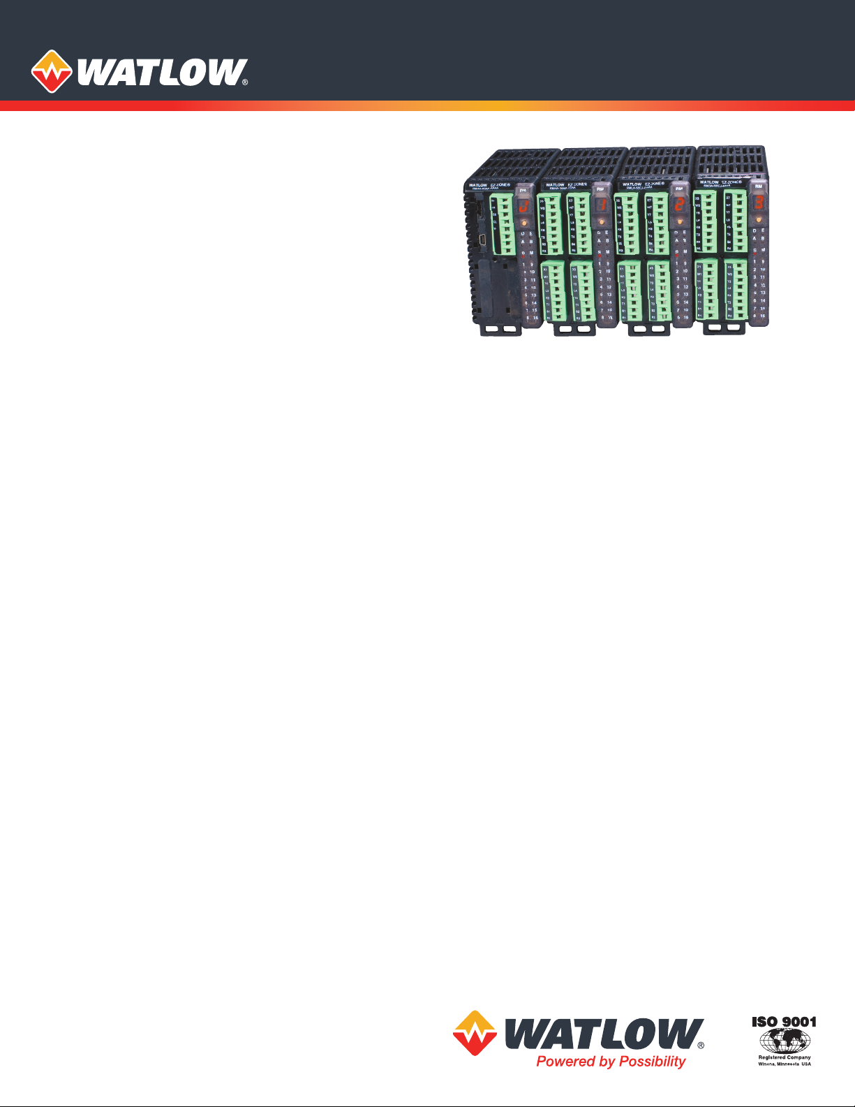
EZ-ZONE® RM Multi-Loop Controller
EZ-ZONE® RM High-Density
Modules Integrate
Temperature, Process,
Limit and Power Control
from 1 to 152 Loops Into
One System
SPECIFICATION SHEET
The EZ-ZONE® RM controller family simplifies thermal
system management. The EZ-ZONE RM controller family
is comprised of six module types: an integrated on-off
or PID control, monitoring and over/under temperature
limit module, a high-density on-off or PID control module,
a high-density limit only module, an input/output (I/O)
expansion module, a high-density monitor/scanner
module and a data logging and field communications
access module. A system is configured by connecting
any combination of module types to address specific
application needs. The EZ-ZONE RM is extremely flexible
and scalable allowing mixing and matching of I/O to
configure one to 152 control loops and up to 256 monitor
points.
Optional integrated controller functions can be
combined or ordered in different quantities:
• PID control loops
• Over/under temperature limit control loops
• 10 and 15 ampere power output/heater driver options
• On-board data logging
• Current measurement input
• Sequencer start up and control function
• Programmable timer and counter functions
• Programmable math and logic options
• Multiple communication protocol options
• Mobile configuration with removable secure digital
(SD) flash card
Benefits of using an integrated controller solution:
• Reduces wiring time and termination complexity
compared to connecting multiple discrete products
• Improves system reliability
• Reduces termination and installation cost
• Eliminates compatibility issues often encountered with
using various discrete components and brands
• Reduces troubleshooting time and downtime costs
because the system can specifically identify any
problems with a sensor, controller, solid state relay (SSR)
power output or heater load
• Complete thermal solution saves engineering time and
labor costs while shortening project schedules
Features and Benefits
Multiple inputs; from one to 152 PID loops of control or
monitor up to 256 analog inputs
• Mix and match I/O to fit any application; from one input
with two outputs to 152 analog inputs with 152 outputs,
or monitor up to as many as 256 analog inputs all in
one system
• Reduces cost because only required loops are purchased
• Allows a common controller platform across many
design applications as both loops and outputs can be
ordered in single increments
Advanced PID control algorithm
• Offers TRU-TUNE®+ adaptive control to provide tighter
control for demanding applications
• Enables auto-tune for fast, efficient start-up
Communication capabilities
• Provides a range of protocol options including universal
serial bus (USB) device port, Modbus® RTU, EtherNet/IP™,
Modbus® TCP, DeviceNet™ and PROFIBUS
USB Port
• Provides data log retrieval
SPLIT-RAIL control
• Allows modules mounted in separate high-voltage and
low-voltage cabinets to function as an integrated system
• Minimizes the length and cost of wire runs and improves
system reliability by locating inputs closer to sensors and
outputs closer to loads
AUTO CLONE
• Reduces time and configuration complexity by
automatically building a new module with the same
parameter settings as the replaced module
SENSOR GUARD
• Prevents unplanned process shutdowns and product
loss by switching to a backup sensor if the primary
sensor fails
Page 2

Additional Key Functions
• Configuration communication port (standard bus)
• Removable modules and connectors
• Ring lug and front-screw terminal options
• Profile ramp soak with 400 total steps
• Retransmit and remote set point input virtually inside
controller eliminating costs for input/output hardware
• User configuration settings can be stored and recalled
• Thermistor input
• Elevated operating range of 0 to 149°F (-18 to 65°C)
• UL® listed, CSA, CE, RoHS, W.E.E.E., FM, SEMI F47-0200,
Class 1, Div. 2 rating on selected models
Common Specifications (Applies to all modules)
Line Voltage/Power
• 20.4 to 30.8VAC/VDC, 50/60Hz ±5%
• Any external power supply used should comply with a
Class 2 or SELV rating (see specific module specification
listing for max. VA power consumption)
• Data retention upon power failure via non-volatile memory
• Compliant with Semi F47-0200, Figure R1-1 voltage sag
requirements
Environment
• 0 to 149°F (-18 to 65°C) operating temperature
• -40 to 185°F (-40 to 85°C) storage temperature
• 0 to 90% RH, non-condensing
Functional Operating Range for RMC, RMH, RML
and RMS
Type J: -346 to 2192°F (-210 to 1200°C)
Type K: -454 to 2500°F (-270 to 1371°C)
Type T: -454 to 750°F (-270 to 400°C)
Type E: -454 to 1832°F (-270 to 1000°C)
Type N: -454 to 2372°F (-270 to 1300°C)
Type C: 32 to 4200°F (0 to 2315°C)
Type D: 32 to 4200°F (0 to 2315°C)
Type F: 32 to 2449°F (0 to 1343°C)
Type R: -58 to 3214°F (-50 to 1767°C)
Type S: -58 to 3214°F (-50 to 1767°C)
Type B: 32 to 3300°F (0 to 1816°C)
RTD (DIN): -328 to 1472°F (-200 to 800°C)
Process: -1999 to 9999 units
Agency Approvals
• UL®/EN 61010 Listed, File E185611, C-UL® C22.2
#61010ANSI/ISA 12.12.01-2007 Class 1, Div. 2-Group A, B, C,
D temperature code T4 (optional)
• UL® 1604 Class 1, Div. 2 (optional)
• EN 60529 IP20
• UL® 50, NEMA 4X, EN 60529 IP66; 1/16 DIN remote user
interface (RUI)
• CSA 610110 CE
• RoHS by design, W.E.E.E.
• FM Class 3545 on limit control versions
• CE
Serial Communications
• All modules ship with standard bus protocol for
configuration and communication with all other
EZ-ZONE products
Implicit Messaging
Number of data members accessible through implicit
messaging
Protocol
Ethernet/IP™ 100 20 40 40 20 40 20
DeviceNet™ 200 20 40 40 20 40 20
RM
System
RMC RMH RML RME RMS RMA
User Interface
• Seven-segment LED, address/protocol indicator
programmed via push button switch
• Communication activity, 2 LEDs
• Error condition of each loop, 4 LEDs
• Output status indication, 16 LEDs
Maximum System Configuration
• One access module plus up to 16 additional control or
expansion modules (any combination), up to 152 loops
Mounting
• DIN-rail specification EN50022, 1.38 x 0.30 in.
(35 x 7.5 mm)
• DIN-rail mounted or chassis mounted with customer
supplied screws
Wiring Termination—Touch-Safe Terminals
• Right angle and front screw type terminal blocks
(slots A, B, D, E)
• Input, power and controller output terminals, touch safe,
removable, 12 to 30 AWG
Programmable Application Blocks
Compare
• Greater than, less than, equal, not equal, greater than or
equal, less than or equal
Counters
• Counts up or down, loads predetermined value on the load
signal. Output is active when the count value equals or
exceeds predetermined target value
Linearization
• Interpolated or stepped relationship
Logic
• And, nand, or, nor, equal, not equal, latch, flip flop
Math
• Average, process scale, deviation scale, differential
(subtraction), ratio (divide), add, multiply, absolute
difference, min., max., square root, sample and
hold, altitude and dew point
Process Value
• Sensor backup, average, crossover, wet/dry bulb,
switch over, differential (subtraction), ratio (divide), add,
multiply, absolute difference, min., max., square root,
altitude, visala and dew point
Special Output Function
• Compressor – turns on-off compressor for one or two
loops (cool and dehumidify with single compressor)
• Motorized valve – turns on-off motor open/closed
outputs causing valve to represent desired power level
• Sequencer – turns on-off up to four outputs to
distribute a single power across all outputs with linear
and progressive load wearing
Timers
• On pulse – produces an output of fixed time on the active
edge of timer run signal
• Delay – output is a delayed start of timer run and off at
same time
• One shot – oven timer
• Retentive – measures timer run signal and output on when
accumulated time exceeds target
Variable
• User value for digital or analog variable
Page 3
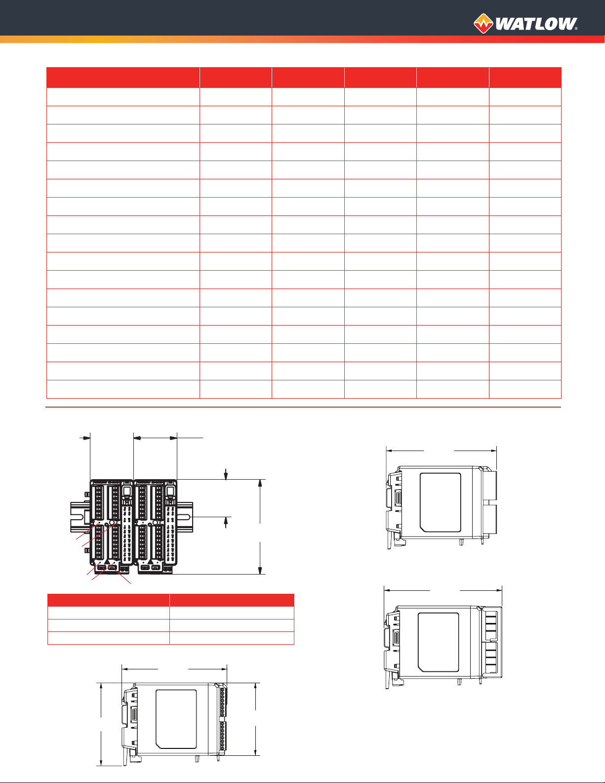
EZ-ZONE RM Family Comparison
Standard Connectors
Standard Connectors
Straight Connectors
5.8 in.
(147.1 mm)
4.57 in.
(116.08 mm)
4 in.
(102 mm)
Standard Connectors
Straight Connectors
Ring Terminal Connectors
5.8 in.
(147.1 mm)
4.57 in.
(116.08 mm)
4 in.
(102 mm)
6.1 in.
(154.4 mm)
Control
Module
Number of modules per system 1 to 16 1 to 16 1 to 16 1 to 16 1 to 16
Number of PID loops per module 1 to 4 4, 8, 12 or 16 0 0 0
Number of limit loops per module 1 to 4 0 4, 8 or 12 0 0
Number of monitoring points per module 1 to 3 0 0 0 4, 8, 12 or 16
Mechanical relays per module 1 to 8 4 or 8 4, 6 or 8 4, 8 or 12 4 or 8
Digital I/O points per module 6 6 or 12 6 or 7 6, 12, 18 or 24 6, 7 or 12
Actions (events) per module 8 24 16 8 16
Alarms per module 8 24 16 8 16
Compare per module 4 24 16 8 24
Counters per module 4 24 16 8 24
Linearization per module 4 24 16 8 24
Logic per module 16 24 16 16 24
High-Density
Control Module
High-Density
Limit Module
Expansion
Module
High-Density
Scanner Module
Math per module 8 24 16 8 24
Process value per module 1 to 4 4, 8, 12 or 16 4, 8 or 12 0 4, 8, 12 or 16
Special output function per module 4 0 0 4 0
Timers per module 4 24 16 8 24
Variable per module 16 24 16 16 24
Dimensional Drawings
2.03 in.
Slot D
Slot E
Slot A
Slot B
(51.56 mm)
Slot C
Add 2.03 in.
(51.56 mm) per module
Connector Type Module Depth in. (mm)
Standard (Right Angle) 5.8 (148)
Straight (Front Screw) 6.1 (155)
Ring Terminal 6.5 (166)
Standard Connectors
5.8 in.
(147.1 mm)
1.75 in.
(44.45 mm)
4.41 in.
(112.04 mm)
Front-Screw Connectors
Ring Terminal Connectors
6.1 in.
(154.4 mm)
6.5 in.
(164.9 mm)
4.57 in.
(116.08 mm)
4 in.
(102 mm)
Page 4

Control Module Specifications (RMC)
(Select an RMC module for 1 to 4 loops of control.)
Line Voltage/Power
• Power consumption: 7 W, 14VA
• Any external power supply used should comply with a
Class 2 or SELV rating
Controller
• User-selectable heat/cool, on-off, P, PI, PD, PID or alarm
action, not valid for limit controllers
Process PID or Over-temperature Limit Mode Options
• Auto-tune with TRU-TUNE+ adaptive control
• Control sampling rates: input = 10Hz, output = 10Hz
(non-divisional)
Isolated Serial Communications
• All modules ship with standard bus protocol for
configuration and communication with all other EZ-ZONE
controllers
• Optional EIA 485, Modbus® RTU
Profile Ramp and Soak (RMC only, not available with
high-density controller)
• Profile engine affects one to four loops
• 25 profiles and 15 sub-routines, 400 steps total
• Option for battery backup and real time clock is via the
access module
Calibration Accuracy
• ±0.1% of span, ±1°C. See user manual for details.
Universal Input
• Thermocouple, grounded or ungrounded sensors
• >20MΩ input impedance
• Max. of 2kΩ source resistance
• RTD 2- or 3-wire, platinum, 100Ω and 1000Ω @ 32°F (0°C)
calibration to DIN curve (0.00385Ω/Ω/°C)
• Process, 0-20mA @100Ω, or 0-10VDC @ 20kΩ input
impedance; scalable, 0-50mV
• Potentiometer: 0 to 1,200Ω
• Inverse scaling
• Current: input range is 0 to 50mA, 100Ω input impedance
Response time: 1 second max., accuracy ±1mA typical
Thermistor Input
• 0 to 40kΩ, 0 to 20kΩ, 0 to 10kΩ, 0 to 5kΩ
• 2.252kΩ and 10kΩ base at 77°F (25°C)
Digital Input
• Update rate 10Hz
• Max. input 36VDC at 3mA
• Min. high state 3VDC at 0.25mA
• Max. low state 2V
Dry Contact Input
• Update rate 10Hz
• Min. open resistance 10kΩ, max. closed resistance 50Ω
Current Measurement Input
• Accepts 0-50mA signal (user programmable range)
• Displayed operating range and resolution can be scaled
and are user programmable
Output Hardware
• Switched dc:
• Max. 32VDC open circuit
• Max. current 30mA per single output
• Max. current 40mA per paired outputs (1 & 2, 3 & 4,
5 & 6, 7 & 8)
• Open collector:
• Max. 30VDC @ 100mA
• 6 digital inputs/outputs:
• Switched dc, max. 20VDC @ 40mA, 12VDC @ 80mA
• Open collector, max. 32VDC @ 1.5A, max. 8A per 6
outputs combined
• SSR, Form A, 1A at 50°F (10°C) to 0.5A at 149°F (65°C), 0.5A
@ 24VAC min., 264VAC max., opto-isolated, without contact
suppression
• Electromechanical relay, Form C, 5A, 24 to 240VAC or
30VDC max., resistive load, 100,000 cycles at rated load,
requires a min. load of 20mA at 24V, 125VA pilot duty
• Electromechanical relay, Form A, 5A, 24 to 240VAC or
30VDC max., resistive load, 100,000 cycles at rated load,
requires a min. load of 20mA at 24V, 125VA pilot duty
• NO-ARC relay, Form A, 15A @ 122°F (50°C),
85 to 264VAC, no VDC, resistive load, 2 million
cycles at rated load
• Universal process/retransmit, output range selectable:
• 0 to 10VDC ±15mV into a min. 1,000Ω load with 2.5mV
nominal resolution
• 0 to 20mA ±30µA into max. 800Ω load with 5µA
nominal resolution
• Temperature stability is 100ppm/°C
Page 5

Control Module Ordering Information
Requires 24 to 28VDC power supply, includes communication port for configuration with EZ-ZONE configurator and PC.
Part Number
① ②
EZ-ZONE
Rail
Mount
RM
④
1 =
2 =
3 = Ramp/Soak control with universal input (R/S applies to all loops in module)
4 = Ramp/Soak control with thermistor input (R/S applies to all loops in module)
5 =
6 =
7 =
9 =
⑤
A =
B =
U =
D =
E =
F =
G =
H =
J =
K =
L =
M =
N =
P =
R =
S =
T = None
Y =
Z =
⑥
A = None
1 = Control with universal input
2 = Control with thermistor input
5 = Limit with universal input (only valid Output 3 and 4, options will be B, F, L)
6 =
7 =
R = Auxiliary 2nd input (universal input)
P = Auxiliary 2nd input (thermistor input)
⑦
A =
B =
U =
D =
E =
F =
G =
H =
J =
K =
L =
M =
N =
P =
R =
S =
T = None
Y =
Z =
⑧
A = None
1 = Control with universal input
2 = Control with thermistor input
5 =
6 =
7 =
R = Auxiliary 2nd input (universal input)
P = Auxiliary 2nd input (thermistor input)
③
④
Input 1
Control
Module
Primary
Function
C
Control with universal input
Control with thermistor input
Limit with universal input (only valid Output 1 and 2, options will be
B, F, L)
Limit with thermistor input
B, F, L)
Current transformer input (not valid Output 1 and 2, options are A, B,
N, P, R, S, T)
Custom
Output 1 and 2 Hardware Options
None
None Mechanical relay 5A, Form A
Switched dc/open collector
Switched dc/open collector NO-ARC 15A power control
Switched dc/open collector Switched dc
Switched dc/open collector Mechanical relay 5A, Form A
Switched dc/open collector SSR Form A, 0.5A
Mechanical relay 5A, Form C
Mechanical relay 5A, Form C NO-ARC 15A power control
Mechanical relay 5A, Form C Switched dc
Mechanical relay 5A, Form C Mechanical relay 5A, Form A
Mechanical relay 5A, Form C SSR Form A, 0.5A
Universal process
Universal process Switched dc
Universal process Mechanical relay 5A, Form A
Universal process SSR Form A, 0.5A
SSR Form A, 0.5A NO-ARC 15A power control
SSR Form A, 0.5A SSR Form A, 0.5A
Limit with thermistor input (only valid Output 3 and 4, options will be B, F, L)
Current transformer input (not valid Output 3 and 4, options are N, P, R, S)
None
None Mechanical relay 5A, Form A
Switched dc/open collector
Switched dc/open collector NO-ARC 15A power control
Switched dc/open collector Switched dc
Switched dc/open collector Mechanical relay 5A, Form A
Switched dc/open collector SSR Form A, 0.5A
Mechanical relay 5A, Form C
Mechanical relay 5A, Form C NO-ARC 15A power control
Mechanical relay 5A, Form C Switched dc
Mechanical relay 5A, Form C Mechanical relay 5A, Form A
Mechanical relay 5A, Form C SSR Form A, 0.5A
Universal process
Universal process Switched dc
Universal process Mechanical relay 5A, Form A
Universal process SSR Form A, 0.5A
SSR Form A, 0.5A NO-ARC 15A power control
SSR Form A, 0.5A SSR Form A, 0.5A
Limit with universal input (only valid Output 5 and 6, options will be B, F, L)
Limit with thermistor input (only valid Output 5 and 6, options will be B, F, L)
Current transformer input (not valid Output 5 and 6, options are N, P, R, S)
Output 1 Output 2
Output 3 and 4 Hardware Options
Output 3 Output 4
⑤
Output 1 and
2 Hardware
Options
Input 1 Primary Function
(only valid Output 1 and 2, options will be
Input 2
Input 3
⑥
Input 2
None
None
None
None
SSR Form A, 0.5A
None
None
None
None
SSR Form A, 0.5A
⑦
Output 3 and
4 Hardware
Options
Input 3
⑧
⑨
Output 5 and
6 Hardware
Options
⑨
A =
None
B =
None Mechanical relay 5A, Form A
U =
Switched dc/open collector
D =
Switched dc/open collector NO-ARC 15A power control
E =
Switched dc/open collector Switched dc
F =
Switched dc/open collector Mechanical relay 5A, Form A
G =
Switched dc/open collector SSR Form A, 0.5A
H =
Mechanical relay 5A, Form C
J =
Mechanical relay 5A, Form C NO-ARC 15A power control
K =
Mechanical relay 5A, Form C Switched dc
L =
Mechanical relay 5A, Form C Mechanical relay 5A, Form A
M =
Mechanical relay 5A, Form C SSR Form A, 0.5A
N =
Universal process
P =
Universal process Switched dc
R =
Universal process Mechanical relay 5A, Form A
S =
Universal process SSR Form A, 0.5A
T = None
Y =
SSR Form A, 0.5A NO-ARC 15A power control
Z =
SSR Form A, 0.5A SSR Form A, 0.5A
⑩
A = None
1 = Control with universal input
2 = Control with thermistor input
5 = Limit with universal input (only valid Output 7 and 8, options will be B, F, L)
6 = Limit with thermistor input (only valid Output 7 and 8, options will be
B, F, L)
7 = Current transformer input (not valid Output 7 and 8, options are N, P, R, S)
R = Auxiliary 2nd input (universal input)
P = Auxiliary 2nd input (thermistor input)
⑪
A =
None
B =
None Mechanical relay 5A, Form A
U =
Switched dc/open collector
D =
Switched dc/open collector NO-ARC 15A power control
E =
Switched dc/open collector Switched dc
F =
Switched dc/open collector Mechanical relay 5A, Form A
G =
Switched dc/open collector SSR Form A, 0.5A
H =
Mechanical relay 5A, Form C
J =
Mechanical relay 5A, Form C NO-ARC 15A power control
K =
Mechanical relay 5A, Form C Switched dc
L =
Mechanical relay 5A, Form C Mechanical relay 5A, Form A
M =
Mechanical relay 5A, Form C SSR Form A, 0.5A
N =
Universal process
P =
Universal process Switched dc
R =
Universal process Mechanical relay 5A, Form A
S =
Universal process SSR Form A, 0.5A
T = None
Y =
SSR Form A, 0.5A NO-ARC 15A power control
Z =
SSR Form A, 0.5A SSR Form A, 0.5A
C =
6 digital inputs/outputs (valid option only if Input 4 selection =
⑫
A = Right angle screw connector (standard)
F = Front screw connector (slots A, B, D and E only)
⑬
A = Standard bus
1 =
Standard bus and Modbus® RTU 485 (selectable via dipswitch)
⑭
⑮
Firmware, Overlays, Parameter Settings
AA =
Standard
Replacement connectors hardware only for the entered part number.
AB =
Additional cost for the model can be disregarded as you are only
ordering replacement connectors.
12 =
Class 1, Div. 2 (not available with integrated limit controller or
mechanical relay options)
Custom
XX =
⑩
⑪
Output 7 and
Input 4
Options
Output 5 and 6 Hardware Options
Output 5 Output 6
Output 7 and 8 Hardware Options
Output 7 Output 8
8 Hardware
Connector
Input 4
Connector Style
Enhanced Options
Additional Options
⑫
⑬
Enhanced
Style
None
None
None
None
SSR Form A, 0.5A
None
None
None
None
SSR Form A, 0.5A
Options
⑭ ⑮
Additional
Options
A)
Page 6

High-Density Control Module Specifications (RMH)
(Select an RMH module for 4 to 16 loops of control.)
Line Voltage/Power
• Power consumption: 7 W, 14VA
• Any external power supply used should comply with a
Class 2 or SELV rating
Controller
• User-selectable heat/cool, on-off, P, PI, PD, PID or alarm
action, not valid for limit controllers
Process PID Options
• Auto-tune with TRU-TUNE+ adaptive control
• Control sampling rates: input = 10Hz, output = 10Hz
(non-divisional)
Isolated Serial Communications
• All modules ship with standard bus protocol for
configuration and communication with all other
EZ-ZONE controllers
• Optional EIA 485, Modbus® RTU
Calibration Accuracy
• ±0.1% of span, ±1°C. See user manual for details.
Universal Input
• Thermocouple, grounded or ungrounded sensors
• >20MΩ input impedance
• Max. of 2kΩ source resistance
• RTD 2-wire, platinum, 100Ω and 1000Ω @ 32°F (0°C)
calibration to DIN curve (0.00385Ω/Ω/°C)
• Process, 0-20mA @100Ω, or 0-10VDC @ 20kΩ input
impedance; scalable, 0-50mV
Thermistor Input
• 0 to 40kΩ, 0 to 20kΩ, 0 to 10kΩ, 0 to 5kΩ
• 2.252kΩ and 10kΩ base at 77°F (25°C)
Digital Input
• Update rate 10Hz
• Max. input 36VDC at 3mA
• Min. high state 3VDC at 0.25mA
Dry Contact Input
• Update rate 10Hz
• Min. open resistance 10kΩ, max. closed resistance 50Ω
Output Hardware
• 6 digital inputs/outputs:
• Switched dc, max. 20VDC @ 40mA, 12VDC @ 80mA
• Open collector, max. 32VDC @ 1.5A, max. 8A per
6 outputs combined
• Electromechanical relay, Form A, 5A, 24 to 240VAC or
30VDC max., resistive load, 100,000 cycles at rated load,
requires a min. load of 20mA at 24V, 125VA pilot duty
Tri-Process (Three universal process/retransmit outputs)
• Output range selections: 0 to 10VDC into a min. 4KΩ
load
• 0 to 20mA into max. 400Ω load
Quad SSR
• Four SSRs at 2A each. SSRs are grouped in 2-pairs with
each sharing a common. See table below.
Maximum Current Per Relay
Ambient Temp.
-18 to 20°C 2A 1.5A
20 to 65°C 1A 0.75A
1 Quad SSR Card
More than 1 Quad
SSR Card
High-Density Control Module Ordering Information
Requires 24 to 28VAC/VDC power supply, includes communication port for configuration with EZ-ZONE configurator and PC.
Part Number
① ②
EZ-ZONE
Rail
Mount
RM
④
A = Right angle screw connector (standard)
F = Front screw connector
S = Custom
⑤
1 = 4 universal inputs (T/C, RTD 2-wire, 0-10VDC, 0-20mA)
2 = 4 thermistor inputs with control loops
⑥
A = None
1 = 4 universal inputs (T/C, RTD 2-wire, 0-10VDC, 0-20mA)
2 = 4 thermistor inputs with control loops
⑦
A = None
1 =
2 = 4 thermistor inputs with control loops
C = 6 digital I/O
F = 3 universal process/retransmit outputs
J = 4 mechanical relay 5A, Form A
L = 4 SSR’s at 2A each. SSR’s grouped in 2-pairs with each pair
③
Control
Module
④
Connector
Style
H
Connector Style/Custom Product
with control loops
with control loops
4 universal inputs (T/C, RTD 2-wire, 0-10VDC, 0-20mA) with
control loops
sharing a common
⑤
Slot A
-
Slot A
Slot B
Slot D
⑥
Slot B⑦Slot D⑧Slot E
⑨
Future
Option
A
-
⑧
A = None
1 =
2 = 4 thermistor inputs with control loops
C = 6 digital I/O
F = 3 universal process/retransmit outputs
J = 4 mechanical relay 5A, Form A
L = 4 SSR’s at 2A each. SSR’s grouped in 2-pairs with each pair
⑩
A = Standard bus
1 =
⑪
Firmware, Overlays, Parameter Settings
AA =
AB = Replacement connectors hardware only for the entered
XX =
⑩
Enhanced
Options
4 universal inputs (T/C, RTD 2-wire, 0-10VDC, 0-20mA) with
control loops
sharing a common
Standard bus and Modbus® RTU 485 (user-selectable)
⑫
Standard
part number
Custom
⑪ ⑫
Additional
Options
Slot E
Enhanced Options
Additional Options
Page 7

High-Density Limit Module Specifications (RML)
(Select an RML module for 4 to 12 safety limits.)
Line Voltage/Power
• Power consumption: 7 W, 14VA
• Any external power supply used should comply with a
Class 2 or SELV rating
Isolated Serial Communications
• All modules ship with standard bus protocol for
configuration and communication with all other
EZ-ZONE controllers
• Optional EIA 485, Modbus® RTU
Calibration Accuracy
• ±0.1% of span, ±1°C. See user manual for details
Universal Input
• Thermocouple, grounded or ungrounded sensors
• >20MΩ input impedance
• Max. of 2kΩ source resistance
• RTD 2-wire, platinum, 100Ω and 1000Ω @ 32°F (0°C)
calibration to DIN curve (0.00385Ω/Ω/°C)
• Process, 0-20mA @100Ω, or 0-10VDC @ 20kΩ input
impedance; scalable, 0-50mV
Thermistor Input
• 0 to 40kΩ, 0 to 20kΩ, 0 to 10kΩ, 0 to 5kΩ
• 2.252kΩ and 10kΩ base at 77°F (25°C)
Digital Input
• Update rate 10Hz
• Max. input 36VDC at 3mA
• Min. high state 3VDC at 0.25mA
Dry Contact Input
• Update rate 10Hz
• Min. open resistance 10kΩ, max. closed resistance 50Ω
Output Hardware
• 6 digital inputs/outputs:
• Switched dc, max. 20VDC @ 40mA, 12VDC @ 80mA
• Open collector, max. 32VDC @ 1.5A, max. 8A per
6 outputs combined
• Electromechanical relay, Form A, 5A, 24 to 240VAC or
30VDC max., resistive load, 100,000 cycles at rated load,
requires a min. load of 20mA at 24V, 125VA pilot duty
High-Density Limit Module Ordering Information
Requires 24 to 28VAC/VDC power supply, includes communication port for configuration with EZ-ZONE configurator and PC.
Part Number
① ②
EZ-ZONE
Rail
Mount
RM
④
A = Right angle screw connector (standard)
F = Front screw connector
S = Custom
⑤
5 = 4 universal inputs (T/C, RTD 2-wire, 0-10VDC, 0-20mA) with limit
6 = 4 thermistor inputs with limit control loops
⑥
A = None
5 = 4 universal inputs (T/C, RTD 2-wire, 0-10VDC, 0-20mA) with limit
6 = 4 thermistor inputs with limit control loops
⑦
A = None
5 = 4 universal inputs (T/C, RTD 2-wire, 0-10VDC, 0-20mA) with limit
6 = 4 thermistor inputs with limit control loops
J = 4 mechanical relay 5A, Form A
C = 6 digital I/O*
③
Limit
Module
L
control loops
control loops
control loops
④
Connector
Style
Connector Style/Custom Product
⑤
Slot A
- -
Slot A
Slot B
Slot D
⑥
Slot B⑦Slot D⑧Slot E
⑨
Future
Option
A
B =
A = Standard bus
Firmware, Overlays, Parameter Settings
AA =
* Reset limits via digital input, EZ key on RUI or communications commands
⑩
Enhanced
Options
⑧
J = 4 mechanical relay 5A, Form A
1 digital input and 2 mechanical relays, 5A (1 Form A and
1 Form C)*
⑩
1 =
Standard bus and Modbus® RTU 485* (user-selectable)
⑪
⑫
Standard
AB = Replacement connectors hardware only for the entered part
number.
XX =
Custom
⑪ ⑫
Additional
Options
Slot E
Enhanced Options
Additional Options
Page 8

Expansion Module Specifications (RME)
(Select an RME module for additional inputs and outputs
and higher amperage outputs.)
Line Voltage/Power
• Power consumption: 7 W, 14VA
• Any external power supply used should comply with a
Class 2 or SELV rating
Serial Communications
• All modules ship with standard bus protocol for
configuration and communication with all
other EZ-ZONE products
Wiring Termination—Touch Safe Terminals
• Right angle and front-screw type terminal blocks
(slots A, B, D, E)
• Input, power and controller output terminals, touch
safe, removable, 12 to 30 AWG
• Ring lug terminal blocks (slots A and D only)
• Input, power and controller output terminals are
touch safe and removable
Digital Input
• Update rate 10Hz
• Max. input 36VDC at 3mA
• Min. high state 3VDC at 0.25mA
Dry Contact
• Min. open resistance 100kΩ
• Max. closed resistance 50Ω
Output Hardware (6 digital inputs/outputs)
• Update rate 10Hz
• Switched dc
• Output voltage 20VDC max.
• Max. supply current source 40mA at 20VDC and 80mA
at 12VDC
• Open collector
• Switched voltage max. 32VDC
• Max. switched current per output 2.5A
• Max. switched current for all six outputs combined 10A
Dual Solid State Relay
• Two SSR board option, Form A, 10A max. each
SSRs combined @ 24VAC min., 264VAC max.,
opto-isolated, without contact suppression, max. resistive
load 10A per output at 240VAC, max. 20A per card at 122°F
(50°C), max. 12A per card at 149°F (65°C)
Four Mechanical Relay
• Four electro mechanical relays, Form A, 5A, 24 to
240VAC or 30VDC max., resistive load, 100,000 cycles at
rated load. Requires a min. load of 20mA at 24V, 125VA
pilot duty
Tri-Process (Three universal process/retransmit outputs)
• Output range selections: 0 to 10VDC into a min. 4KΩ load
• 0 to 20mA into max. 400Ω load
Quad SSR
• Four SSRs at 2A each. SSRs are grouped in 2-pairs with each
sharing a common.
Maximum Current Per Relay
Ambient Temp.
-18 to 20°C 2A 1.5A
20 to 65°C 1A 0.75A
1 Quad SSR Card
More than 1 Quad
SSR Card
Expansion Module Ordering Information
Requires 24 to 28VDC power supply, includes communication port for configuration with EZ-ZONE configurator and PC.
Part Number
① ②
EZ-ZONE
Rail
Mount
RM
④
A = Right angle screw connector (standard)
F = Front screw connector (slots A, B, D and E only)
R = Ring lug connector (if ordered then slots B and E must be =A)
S = Custom
⑤
A = None
C = 6 digital I/O
F = 3 universal process/retransmit outputs
J = 4 mechanical relay 5A, Form A
K =
2 SSRs, Form A, 10A max. each (if ordered, then slot B must
be =A)
L =
4 SSR’s at 2A each. SSR’s grouped in 2-pairs with each pair
sharing a common
T =
Quad inputs for external current transformers. Can do either
single-phase or three-phase system measurement for all
hardware outputs ordered within the expansion module.
⑥
A = None
C = 6 digital I/O
F = 3 universal process/retransmit outputs
J = 4 mechanical relay 5A, Form A
L = 4 SSR’s at 2A each. SSR’s grouped in 2-pairs with each pair
sharing a common
T = Quad inputs for external current transformers. Can do either
single-phase or three-phase system measurement for all
hardware outputs ordered within the expansion module.
③
Expansion
Module
E
④
Connector
Style
Connector Style/Custom Product
⑤
Slot A
-
Slot A
Slot B
⑥
Slot B⑦Slot D⑧Slot E
⑨ ⑩
Future
Options
AA
-
⑦
A = None
C = 6 digital I/O
F = 3 universal process/retransmit outputs
J = 4 mechanical relay 5A, Form A
K =
L = 4 SSR’s at 2A each. SSR’s grouped in 2-pairs with each pair
T = Quad inputs for external current transformers. Can do either
⑧
A = None
C = 6 digital I/O
F = 3 universal process/retransmit outputs
L =
T =
⑪
Firmware, Overlays, Parameter Settings
AA =
AB = Replacement connectors hardware only for the entered part
12 =
XX =
⑪ ⑫
Additional
Options
Slot D
2 SSRs, Form A, 10A max. each (if ordered, then slot E must
be = A)
sharing a common
single-phase or three-phase system measurement for all
hardware outputs ordered within the expansion module.
Slot E
4 SSR’s at 2A each. SSR’s grouped in 2-pairs with
each pair sharing a common
Quad inputs for external current transformers. Can do either
single-phase or three-phase system measurement for all
hardware outputs ordered within the expansion module.
⑫
Standard
number. Additional cost for the model can be disregarded as
you are only ordering replacement connectors.
Class 1, Div. 2 (not available with integrated limit controller or
mechanical relay options)
Custom
Additional Options
Page 9

High-Density Scanner Module Specifications (RMS)
(Select an RMS module for 4 to 16 auxiliary analog inputs.)
Line Voltage/Power
• Power consumption: 7 W, 14VA
• Any external power supply used should comply with a
Class 2 or SELV rating
Isolated Serial Communications
• All modules ship with standard bus protocol for
configuration and communication with all EZ-ZONE
controllers
• Optional EIA 485, Modbus® RTU
Calibration Accuracy
• ±0.1% of span, ±1°C. See user manual for details.
Universal Input
• Thermocouple, grounded or ungrounded sensors
• >20MΩ input impedance
• Max. of 2kΩ source resistance
• RTD 2-wire, platinum, 100Ω and 1000Ω @ 32°F (0°C)
calibration to DIN curve (0.00385Ω/Ω/°C)
• Process, 0-20mA @100Ω, or 0-10VDC @ 20kΩ input
impedance; scalable, 0-50mV
Thermistor Input
• 0 to 40kΩ, 0 to 20kΩ, 0 to 10kΩ, 0 to 5kΩ
• 2.252kΩ and 10kΩ base at 77°F (25°C)
Digital Input
• Update rate 10Hz
• Max. input 36VDC at 3mA
• Min. high state 3VDC at 0.25mA
Dry Contact Input
• Update rate 10Hz
• Min. open resistance 10kΩ, max. closed resistance 50Ω
Output Hardware
• 6 digital inputs/outputs:
• Switched dc, max. 20VDC @ 40mA, 12VDC @ 80mA
• Open collector, max. 32VDC @ 1.5A, max. 8A per
6 outputs combined
• Electromechanical relay, Form A, 5A, 24 to 240VAC or
30VDC max., resistive load, 100,000 cycles at rated load,
requires a min. load of 20mA at 24V, 125VA pilot duty
High-Density Scanner Module Ordering Information
Requires 24 to 28VAC/VDC power supply, includes communication port for configuration with EZ-ZONE configurator and PC.
Part Number
① ②
EZ-ZONE
Rail
Mount
RM
④
A = Right angle screw connector (standard)
F = Front screw connector
S = Custom
⑤
R =
P = 4 thermistor inputs without control loops
⑥
A =
R = 4 universal inputs (T/C RTD 2-wire, 0-10VDC, 0-20mA) without
P =
⑦
A = None
R =
P = 4 thermistor inputs without control loops
C = 6 digital I/O
F = 3 universal process/retransmit outputs
J = 4 mechanical relay 5A, Form A
L = 4 SSR’s at 2A each. SSR’s grouped in 2-pairs with each pair
③
Scanner
Module
④
Connector
Style
S
Connector Style/Custom Product
4 universal inputs (T/C, RTD 2-wire, 0-10VDC, 0-20mA) without
control loops
None
control loops
4 thermistor inputs without control loops
4 universal inputs (T/C RTD 2-wire, 0-10VDC, 0-20mA) without
control loops
sharing a common
⑤
Slot A
- -
Slot A
Slot B
Slot D
⑥
Slot B⑦Slot D⑧Slot E
⑨
Future
Option
A
⑧
A = None
R =
P = 4 thermistor inputs without control loops
B = 1 digital input and 2 mechanical relays, 4A
C = 6 digital I/O
F = 3 universal process/retransmit outputs
J = 4 mechanical relay 5A, Form A
L = 4 SSR’s at 2A each. SSR’s grouped in 2-pairs with
⑩
A = Standard bus
1 =
⑪
Firmware, Overlays, Parameter Settings
AA =
AB = Replacement connectors hardware only for the entered
XX =
⑩
Enhanced
Options
4 universal inputs (T/C RTD 2-wire, 0-10VDC, 0-20mA) without
control loops
each pair sharing a common
Standard bus and Modbus® RTU 485 (user-selectable)
⑫
Standard
part number
Custom
⑪ ⑫
Additional
Options
Slot E
Enhanced Options
Additional Options
Page 10

Access Module Specifications (RMA)
(Select an RMA module for communication protocol
options, datalogging and automatic configuration backup.)
Line Voltage/Power
• Power consumption: 4 W, 9VA
• Any external power supply used should comply with a
Class 2 or SELV rating
Isolated Serial Communications
• All modules ship with standard bus protocol for
configuration and communication connection to all
EZ-ZONE products
Additional Communication Options
• EIA 232/485, Modbus® RTU
• EtherNet/IP™, Modbus® TCP, 10 BASE-T/100 BASE-TX
• DeviceNet™
• PROFIBUS DP (future option, contact factory)
• USB, controller recognized as a device
Note: If an access module is present, all other modules must
have Modbus® disabled in order to achieve communications
with all of the modules.
USB
• USB 1.1 device only
• Mini USB connector type
• Recognized as a mass storage device
Real Time Clock with Battery Backup
• Accuracy (typical): +/- 30ppm at 77°F (25°C)
• +30/-100ppm overtemperature operating range
• Battery type and typical lifetime rating: 10 years at
77°F (25°C)
• Lithium battery used, recycle properly
Data Logging
• 200 points
• File storage on-board module
• Comma separated value (CSV) file type
• Export files via removable SD micro memory card or
USB communications port
Memory Card
• Removable SD micro card
• 2G SD memory card provided, also accepts other storage
space amounts
• -4 to 185°F (-20 to 85°C) ambient rating, non-volatile
memory
• Information access to configuration files and the ability to
store module auto-configuration settings and datalog files
if options have been ordered
Auto-configuration File Backup
• Limited memory can support up to four modules
• Limited memory is fixed on board
• Unlimited memory can support up to 16 modules
• Unlimited memory utilizes removable SD micro
card option
Note: All module parameters are backed up in memory
except for USER SET 1 and USER SET 2 parameter settings and
address.
Access Module Ordering Information
Requires 24 to 28VDC power supply, includes communication port for configuration with EZ-ZONE configurator and PC.
Part Number
① ②
EZ-ZONE
Rail
Mount
RM
④
A = Right angle screw connector (standard)
F = Front screw connector (slots B, and E only)
S = Custom
⑤
A = Standard
⑥
A = None
2 = Modbus® RTU 232/485
3 = EtherNet/IP™, Modbus®/TCP
5 = DeviceNet™
6 = PROFIBUS DP
⑦
A = None
B = Battery backup and real time clock for profile ramp and soak
⑧ System Configuration and Data Logging Options
Order
Option
A
B
Y
D
③
Access
Module
④
Connector
Style
A
Communications Options
Ramp/Soak Functions
Limited Auto-
Configuration
USB “Device”
Communication
✓
✓ ✓
File Backup for
Up to
4 Modules
✓
⑤
Future
Option
A
-
Connector Style
Future Option
Unlimited Auto-
Configuration
File Backup
for Up to
16 Modules
✓
✓
⑥
Comms.
Options
On-Board Data
✓ ✓
Ramp/
Functions
Logging
⑦
Soak
System Config.
& Data Logging
Options
Mobile Data
(2G SD Card)
✓
✓
⑧
⑨ ⑩
Future
Options
AA
-
USB Device Configuration: USB access to configuration files (and data log
files if data logging option is ordered) stored via on-board SD memory card.
PC access to product via standard bus protocol.
Auto-Configuration Backup: Limited fixed on board memory can support
backing up configuration files for a maximum of four modules. The unlimited
option utilizes a SD memory card to enable configuration file backup for up
to 16 modules. Feature can be used for cloning configuration files to multiple
modules or for easy field replacement to limit downtime.
Data Logging: Data log files stored on 2G SD memory card. Data files can
be exported via USB communication port transfer or removing SD card into
external card reader. Watlow reserves the right to ship a larger memory
amount at any point in time.
Mobile Data: Transfer configuration files (and data logging files
if data logging option is ordered) via removable SD memory card.
⑪
⑫
Firmware, Overlays, Parameter Settings
AA =
Standard
AB = Replacement connectors hardware only for the entered part
number. Additional cost for the model can be disregarded as
you are only ordering replacement connectors.
12 =
Class 1, Div. 2 (not available with integrated limit controller or
mechanical relay options)
XX =
Custom
⑪ ⑫
Additional
Options
Additional Options
Page 11

Compatible Accessories
Specifications for Basic Remote User Interface (RUI) EZKB
Operator Interface
• Dual 4 digit, 7 segment LED displays
• Forward, backward, up and down keys plus a customer
programmable function key - EZ key
• Typical display update rate: 1Hz
• Agency approved to IP65/NEMA 4X
• Standard bus ships with all units. Options: EIA 232/485
Modbus® RTU, EtherNet/IP™/TCP Modbus® or DeviceNet™,
PROFIBUS DP
Line Voltage/Power
• 100 to 240VAC, +10/-15%; (85-264VAC) 50/60Hz, ±5%
• 24VAC/VDC, +10/-15%; 50/60Hz, ±5%
2.05 in.
(52.07 mm)
2.05 in.
(52.07 mm)
EZ-ZONE Configurator Software
The EZ-ZONE configurator software is used to set up Watlow
EZ-ZONE products in one simple process. It works without
requiring the purchase of any communication options because
it uses the standard bus communications protocol that is
included with all EZ-ZONE products. EZ-ZONE configurator
can be used for on-line and off-line configurations and
downloading previously saved setups. It is available as a
FREE download at www.watlow.com.
SpecView
Basic RUI
Front View
Depth Dimensions for RUI: long case 4 in. (101.6 mm),
short case 2.33 in. (59.10 mm)
COMPOSER® with INTUITION®
COMPOSER® with INTUITION® is Watlow’s new software
for configuring F4T and EZ-ZONE RM controllers. It is used
to set up functions such as control loops, profiles and
alarms and link them to controller inputs and outputs.
COMPOSER can be used to edit and save configurations
while communicating with controllers and to download
previously saved setups. It works without requiring the
purchase of any communication options and is available
as a FREE download at www.watlow.com.
SpecView is designed for industrial users and includes
features such as data logging, trending and support for bar
code readers and touch screens. Errors are reduced for any
process by creating application-specific screens. The software
provides a historical replay option, easy-to-use recipe
features and remote access options, including LAN, internet
and modem.
Operator Interface Terminals (OIT)
Silver Series touchscreen operator interface terminals provide a
customizable user interface and log and graph data for Watlow
controllers and other devices. A Silver Series operator interface
terminal, paired with Watlow controllers, is the perfect solution
for industrial processes or machine control applications.
Page 12

Accessories (continued)
Power Supplies
• AC/DC power supply converter 90-264VAC to
24VDC volts.
• P/N 0847-0299-0000 – 31 W
• P/N 0847-0300-0000 – 60 W
• P/N 0847-0301-0000 – 91 W
EZ-ZONE RM Product Documentation
• User’s manual – electronic DVD P/N 0601-0001-0000
• Table of manuals in various languages (see below)
User Documentation RMC RMH RML RME RMS RMA
English 0600-0070-0000 0600-0074-0000 0600-0075-0000 0600-0073-0000 0600-0071-0000 0600-0072-0000
German 0600-0070-0001 0600-0074-0001 0600-0075-0001 0600-0073-0001 0600-0071-0001 0600-0072-0001
Japanese 0600-0070-0002 0600-0074-0002 0600-0075-0002 0600-0073-0002 0600-0071-0002 0600-0072-0002
Korean 0600-0070-0003 0600-0074-0003 0600-0075-0003 0600-0073-0003 0600-0071-0003 0600-0072-0003
French 0600-0070-0004 0600-0074-0004 0600-0075-0004 0600-0073-0004 0600-0071-0004 0600-0072-0004
Italian 0600-0070-0005 0600-0074-0005 0600-0075-0005 0600-0073-0005 0600-0071-0005 0600-0072-0005
Spanish 0600-0070-0006 0600-0074-0006 0600-0075-0006 0600-0073-0006 0600-0071-0006 0600-0072-0006
Chinese
0600-0070-0007 0600-0074-0007 0600-0075-0007 0600-0073-0007 0600-0071-0007 0600-0072-0007
Watlow®, EZ-ZONE®, TRU-TUNE®, COMPOSER®, and INTUITION® are registered
trademarks of Watlow Electric Manufacturing Company.
UL® is a registered trademark of Underwriter’s Laboratories, Inc.
Modbus® is a registered trademark of Schneider Automation Incorporated.
DeviceNet™ and EtherNet/IP™ are trademarks of Open DeviceNet Vendors
Association.
PROFIBUS is a registered trademark of PROFIBUS Nutzerorganisation e.V.
(PNO).
Powered by Possibility
To be automatically connected to the nearest
North American Technical Sales Oce:
1-800-WATLOW2 • www.watlow.com
inquiry@watlow.com
©2016 Watlow Electric Manufacturing Company all rights reserved.
International Technical Sales Offices:
Austria +43 6244 20129 0
Australia +61 3 9335 6449
China +86 21 3532 8532
France +33 (0) 1 41 32 79 70
Your Authorized Watlow Distributor Is:
India +91 40 6661 2700
Italy +39 02 4588841
Japan +81 3 3518 6630
Korea +82 2 2169 2600
Mexico +52 442 256 2200
Singapore +65 6773 9488
Spain +34 91 675 1292
Taiwan +886 7 288 5168
UK +44 (0) 115 964 0777
WIN-EZRM-0416
 Loading...