

Page 1
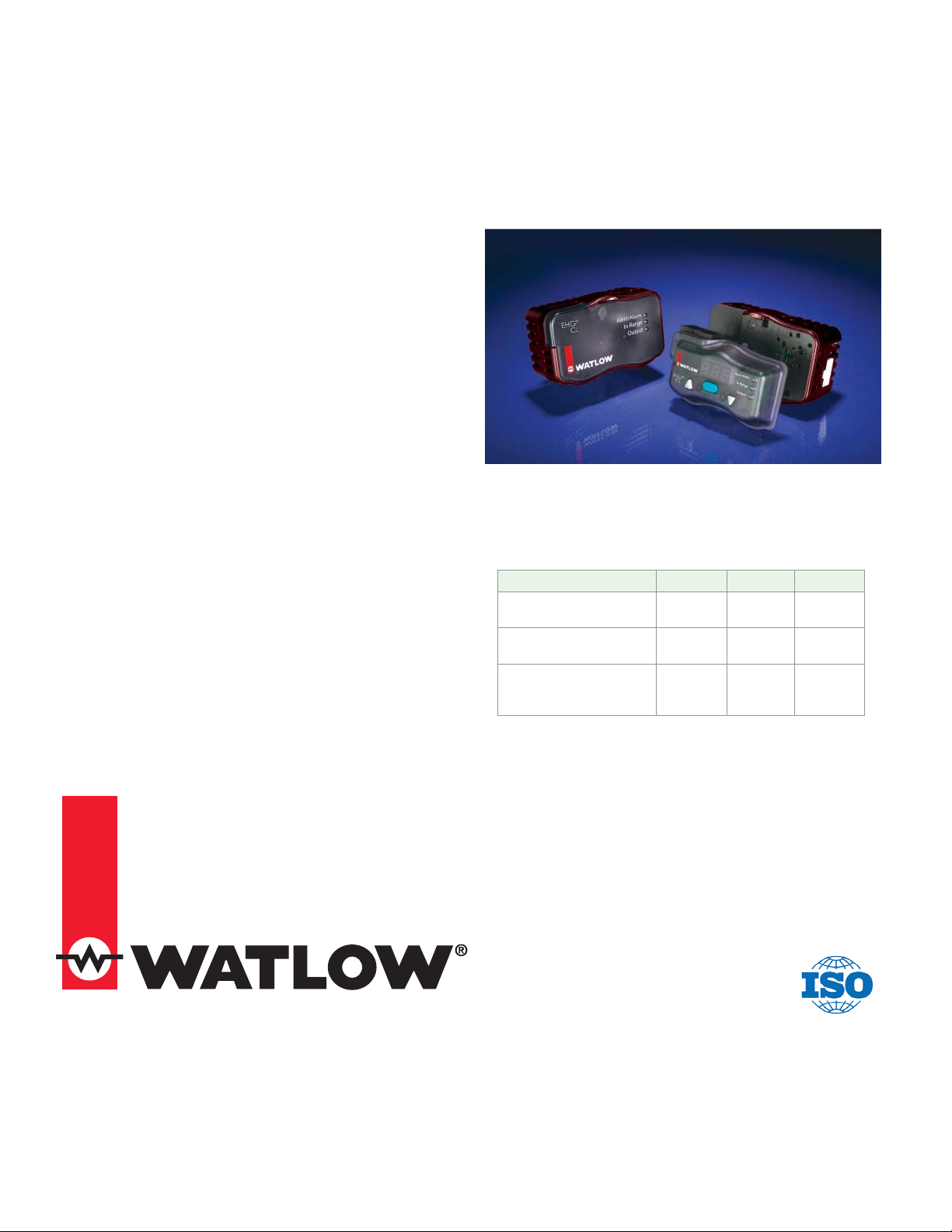
Series EHG CL
Integrated Temperature Controller
User’s Guide
The Series EHG CL is a powerful instrument that integrates a temperature process controller, high-low temperature alert, and power switching with a safety high
limit that meets UL® 1998 and CE 60730 requirements.
The optional display and communications modules can
be easily upgraded in the field to provide a digital display, adjustable control parameters, RS-485 MODBUS
communications and other interface features. The compact design, inherent reliability and integrated safety
limit functions make this control a tremendous value.
The control is designed for easy integration with Watlow heaters providing additional value to simplify the
engineering and component count on new equipment.
CE compliance and UL recognition will reduce time and
costs necessary for global agency testing and validation
for OEMs.
Features
Standard Base Module
• Two, type K thermocouple inputs: process temperature
controller and safety limit
• Process temperature output: 10 amp “NO ARC” relay
• Safety limit: 10 amp relay
• On-off and PID temperature control algorithm: Upgraded via communications to PID algorithm (minimum
cycle time 5 seconds)
0600-0091-0000 Rev. A
September 2012
Integrated Temperature Control
• Standard Molex Connectors
• Dimensions
Configuration Width Depth Height
Basic unit 88.8 mm
Control with mounting
bracket
Control with communicatons-display module &
mounting bracket
Optional Communications Module
• Field adjustable set point
• Access to PID parameters
• Modbus RTU Communications
• RS-485
• 3-character, 7-segment LED display
• User Interface Software
The Series EHG CL User’s Guide is copyrighted by
Watlow Winona, Inc., © September 2012, with all rights
reserved.
Patent Pending
1241 Bundy Boulevard
Phone: (507) 454-5300; Fax: (507) 452-4507
http://www.watlow.com
(3.496 in)
88.8 mm
(3.496 in)
88.8 mm
(3.496 in)
Watlow Winona
Winona, MN 55987
40.2 mm
(1.582 in)
48.4 mm
(1.907 in)
63.6 mm
(2.503)
55.8 mm
(2.196 in)
55.8 mm
(2.196 in)
55.8 mm
(2.196 in)
Page 2
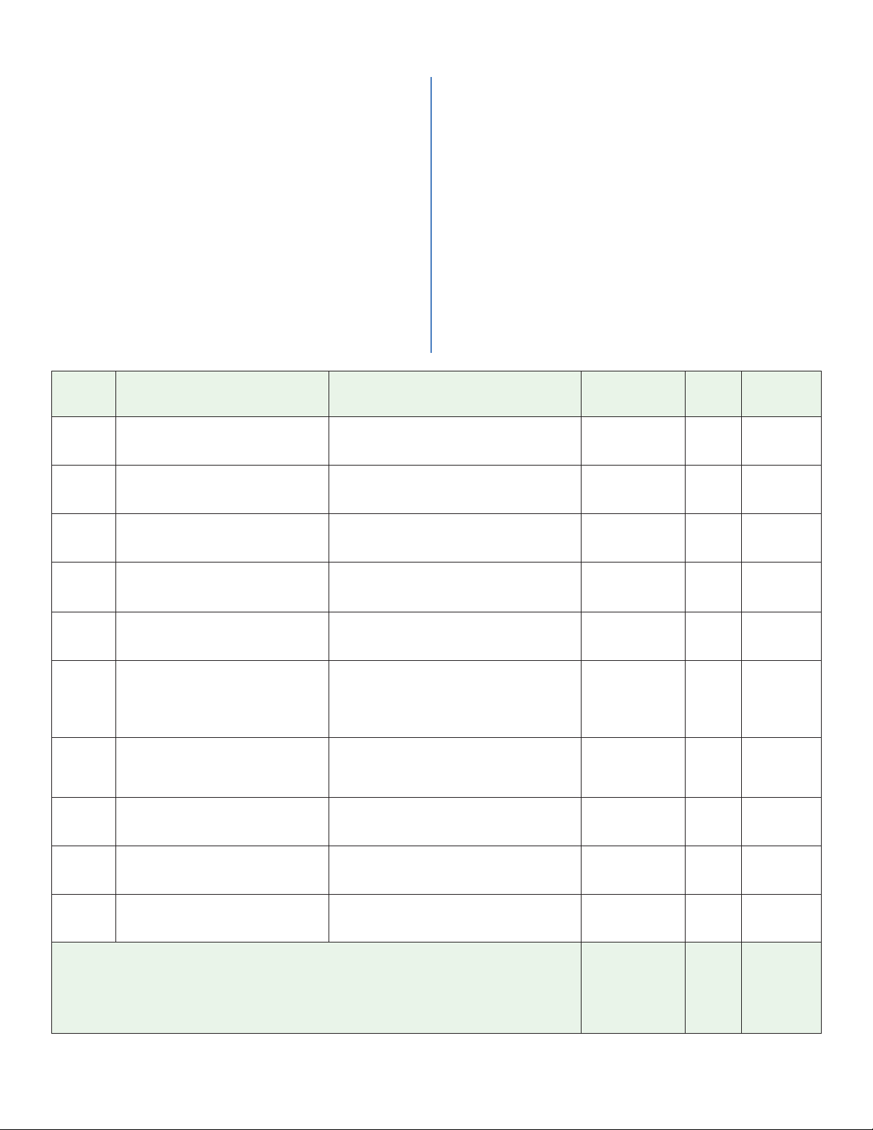
Navigating the Series EHG CL with the Front Panel
The three-character display normally shows the process
temperature. To view and change the existing Set Point
value follow the steps below:
1. Press the Mode Key once. The right decimal point
will illuminate when viewing the Set Point value.
2. Press the Up-Arrow or Down-Arrow Key to change
the Set Point.
3. Press the Mode Key again to return to the process
temperature display.
The display will automatically return to showing the
process temperature after three seconds.
To view or change parameter values follow the steps
below:
1. Hold down both the Up-Arrow and Down-Arrow Keys
This will display the Set Point High Limit prompt.
2. Press the Mode Key to view the other parameter
3. Press the Up-Arrow or Down-Arrow Key once to view
4. Press the Up-Arrow or Down-Arrow Key to increase
5. Press the Mode Key to again display the prompt and
6. Press the Mode Key at the Display Build Number
for five seconds.
prompts.
a parameter’s value.
or decrease that value.
again to display the next prompt.
prompt to return to the process value display.
Display Parameter Name & Description Range Default
Process Value Controller
Numeric
Numeric
No Display
No Display
No Display
No Display
No Display
No Display
[SLA]
[SLA]
[Cnt]
[Cnt]
Note:
All values above 999 will be rounded off to fit in the three-character display. Full values can be
read with other interfaces.
Note:
The EHG CL does not support Modbus function code 16 (0x10) Write Multiple Registers. Parameter values must be written individually with function code 6 (0x06) Write Single Registers.
View the present Process Value.
Closed Loop Set Point
Set the set point that the controller
will automatically control to.
Heat Output Power
Read (via Modbus communications)
the present heat output power level.
Alert Status
Read (via Modbus communications)
the present alert status.
Process Comparison Value
Set or read (via Modbus communications) the Process Comparison Value.
Limit Status
Read (via Modbus communications)
the present condition of the limit.
Controller Sensor Status
Read (via Modbus communications)
the present status of the controller
sensor.
Limit Sensor Value
View the present value of the limit
sensor.
Limit High Set Point
Set the high process value that will
trigger the limit.
Control Mode Select
Select a control method.
-18 to 537°C (0 to 999°F) 20°C (68°F)
0°C (32°F) to SLA setting 150°C (302°F)
0 to 100% 0
Alert Low (7)
Alert High (8)
Alert None (6)
5 to 50°C (9 to 90°F) 20°C (68°F)
Bit 5 (0x0020)
0 = Not tripped (process value below
limit high set point)
1 = Tripped (process value exceeds
limit high set point)
Bit 2 (0x0004)
0 = Good
1 = Failure
-18 to 537°C (0 to 999°F) 20°C (68°F)
0 to 438°C (32 to 820°F) 200°C (392°F)
[onF]
On-Off (2)
[PId]
PID (3)
Alert None
0
0
on-off
Modbus
Relative
Address
20
34
22
31
68
63
23
60
33
42
Data Type
& Read/
Write
unsigned
integer
R
unsigned
integer
RWE
unsigned
integer
R
unsigned
integer
R
unsigned
integer
RWE
unsigned
integer
R
unsigned
integer
R
unsigned
integer
R
unsigned
integer
RWE
unsigned
integer
RWE
R: Read
W: Write
E: EEPROM
Watlow Controls 2 EHG CL User’s Guide
Page 3
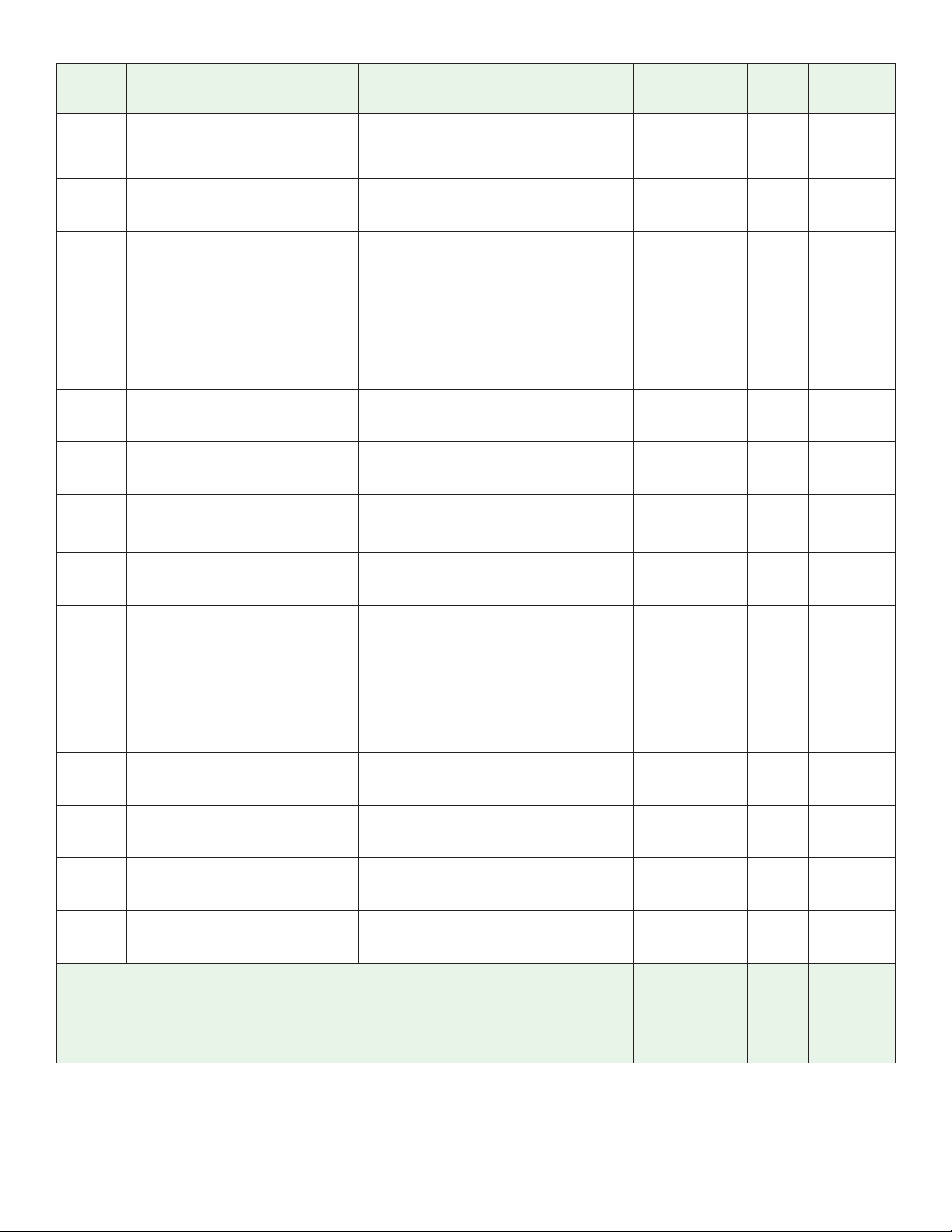
Display Parameter Name & Description Range Default
[HyS]
[HyS]
[`Pb]
[ Pb]
[Int]
[Int]
[dEu]
[dEv]
[`Ct]
[ Ct]
[Abt]
[Abt]
[Adr]
[Adr]
[bAU]
[bAU]
[tU`]
[tU ]
[rpp]
[rPP]
[bru]
[brv]
[bPu]
[bPv]
[bbu]
[bbu]
[dru]
[drv]
[dPu]
[dPv]
[dbu]
[dbv]
Note:
All values above 999 will be rounded off to fit in the three-character display. Full values can be
read with other interfaces.
Note:
The EHG CL does not support Modbus function code 16 (0x10) Write Multiple Registers. Parameter values must be written individually with function code 6 (0x06) Write Single Registers.
On-Off Hysteresis
Set the how far below the set point
the temperature can drop before the
heater turns on.
Proportional Band
Set the proportional band in temperature units.
Integral
Set the integral value in minutes per
repeat.
Derivative
Set the derivative value in minutes.
Cycle Time
Set the cycle time in seconds.
Ambient Temperature
View the ambient temperature.
Modbus Device Address
View and or change the present Modbus address.
Modbus Baud Rate
Select the communication speed.
Temperature Units
Select the temperature scale.
Restore Programmed Parameters
Restore factory default settings.
Base Release Version
View the controller’s base release
version.
Base Prototype Version
View the controller’s base prototype
version.
Base Build Version
View the controller’s base build number.
Display Release Version
View the interface’s release version.
Display Prototype Version
View the interface’s prototype version.
Display Build Version
View the interface’s build number.
3 to 28°C (5 to 50°F) 3°C (6°F)
0 to 68°C (0 to 122°F) 0°C or 0°F
0 to 999 0
0 to 999 0
5 to 60 10
0 to 106°C (0 to 190°F) 43°C (77°F)
1 to 247 1
[`96]
9,600 (15)
[192]
19,200 (16)
[384]
38,400 (17)
[``F]
°F (4)
[``C]
°C (5)
[yes] Yes
9,600
°C
No
[`no] No
0 to 9999
- - - - 48
0 to 9999
- - - - 49
0 to 9999
- - - - 50
0 to 9999
- - - - 11
0 to 9999
- - - - 12
0 to 9999
- - - - 13
Modbus
Relative
Address
41
37
38
39
40
24
15
16
17
- - - - - - - -
Data Type
& Read/
unsigned
integer
RWE
signed integer
RWE
signed integer
RWE
signed integer
RWE
unsigned
integer
RWE
unsigned
integer
R
unsigned
integer
RWE
unsigned
integer
RWE
unsigned
integer
RWE
unsigned
integer
R
unsigned
integer
R
unsigned
integer
R
unsigned
integer
R
unsigned
integer
R
unsigned
integer
R
R: Read
W: Write
E: EEPROM
Write
Watlow Controls 3 EHG CL User’s Guide
Page 4
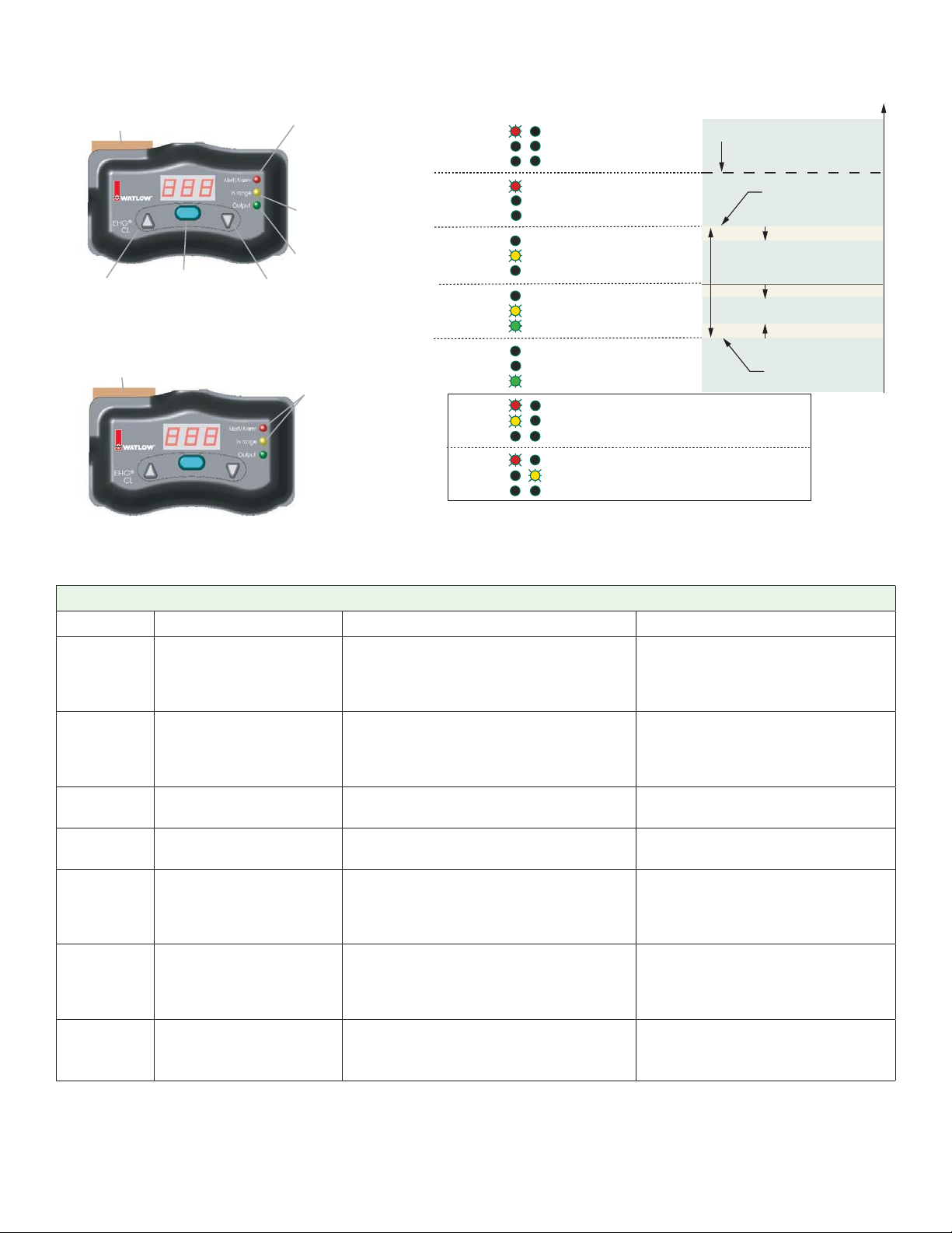
Keys and Indicator Lights
Optional Communications
Connectors
Up-Arrow Key
Increases the
displayed value.
Optional Communications
Connectors
Mode Key
Toggles the display between
the set point and process
temperature. Enters edited
values and advances
to the next prompt.
Down-Arrow Key
Decreases the
displayed value.
Alarm (flashing red)
Indicates that the process
temperature is higher than the
Limit High Set Point.
Alert (solid red)
Indicates that the process
temperature is higher than the
Closed Loop Set Point plus the
High Temperature Alert
Value.
In Range (solid yellow)
Indicates that the process
temperature is in the normal
operating range (see figure at
right).
Output (green)
Indicates that the output is on.
Flashing
Alert/Alarm (red) and
In Range (yellow)
If they are flashing together, that
indicates an Ambient Alarm
(controller temperature higher
than 85°C).
If they are flashing alternately, that
indicates a Health Check Error.
Alert/Alarm
In Range
Output
Alert/Alarm
In Range
Output
Alert/Alarm
In Range
Output
Alert/Alarm
In Range
Output
Alert/Alarm
In Range
Output
Alert/Alarm
In Range
Output
Alert/Alarm
In Range
Output
flashing
flashing
alternate
flashing
Control
Temperature
Relay
Alert Signal
off off
off on
off on
on on
on on
off off Ambient Alarm
[Abt] 85°C
off off Health Check Error
Limit High Set Point [SLA]
Normal Operating Range
Closed Loop Set Point
Closed Loop Set Point
Alarm Hysteresis
Temperature
On-Off Hysteresis [HyS]
Alarm Hysteresis
Closed Loop Set Point
EHG CL Error Codes
Display Description Possible Cause Corrective Action
Flashing
888
Flashing
888
[Er3]
[Er4]
[Er5]
[Er6]
[ER9]
Limit error Sensor has exceeded SLA value or
open thermocouple
Control error Sensor has exceeded SLA value or
open thermocouple
Limit Sensor Error Limit sensor reading out of range (<
-13 or > 640)
Control Sensor Error Control sensor reading out of range
(<-13 or > 640)
Limit Ambient Error Temperature at limit sensor cold junc-
tion (> 185 degrees)
Control Ambient Error Temperature at control cold junction
(> 185 degrees)
HMI Communications
Fault
Loss of communication between base
and display communications module.
See Also E20.
• Set SLA to correct Safety
Limit Value
• Check wiring of sensor
• Check sensor confi guration
• Set SLA to correct Safety
Limit Value
• Check wiring of sensor
• Check sensor confi guration
• Check wiring of sensor
• Check sensor confi guration
• Check wiring of sensor
• Check sensor confi guration
• Check to be certain the EHG
CL is not in an ambient condition greater than 185 degrees
C
• Check to be certain the EHG
CL is not in an ambient condition greater than 185 degrees
C
• Check connection between
EHG CL and display/communications module
Watlow Controls 4 EHG CL User’s Guide
Page 5
EHG CL Error Codes (cont.)
Display Description Possible Cause Corrective Action
[Ahi]
[Alo]
[E91]
[E10]
[E11]
[E12]
[E13]
[E15]
[E16]
[E17]
[E20]
Alarm High Process temp exceeds set point by
value greater than alarm high setting
Alarm Low Process temp below set point by value
greater than alarm low setting
Communications Queue
Full
EEPROM Error EEPROM memory space fails CRC
CRC Error Flash memory space fails CRC check
CPU Clock Error Clock frequency is < 5 MHz or > 13.1
Stack Overfl ow Stack has overfl owed • Contact Technical Support at
AI Function Error Analog reference is < 1.82 or > 2.06
Process Comparison
Error
Data Store Error Data store functions are not set up • Check setting of Process Com-
Base control fi rmware
ID not supported
Communications buffer overfl ow • Contact Technical Support at
check (checksum for parameter space)
(checksum for program space)
MHz
volts
Limit and control sensor readings
differ by value greater than process
comparison value
Base control fi rmware is not compatible with Display Module fi rmware
• Set HTA value to correct high
temperature alert value
• Set LTA value to correct Low
temperature alert value
1-507-494-5656
• Contact Technical Support at
1-507-494-5656
• Contact Technical Support at
1-507-494-5656
• Contact Technical Support at
1-507-494-5656
1-507-494-5656
• Contact Technical Support at
1-507-494-5656
• Check setting of Proces Comparison Value
• Set Process Comparison Value
to correct value
• Check wiring of sensors
parison Value
• Check wiring of sensors
• Check fi rmware compatibility
between Base Control and
Display Module. Revision 20.0
and greater for Base Control
and Display Module are compatible for EHG2-AAAA-0000.
Watlow Controls 5 EHG CL User’s Guide
Page 6
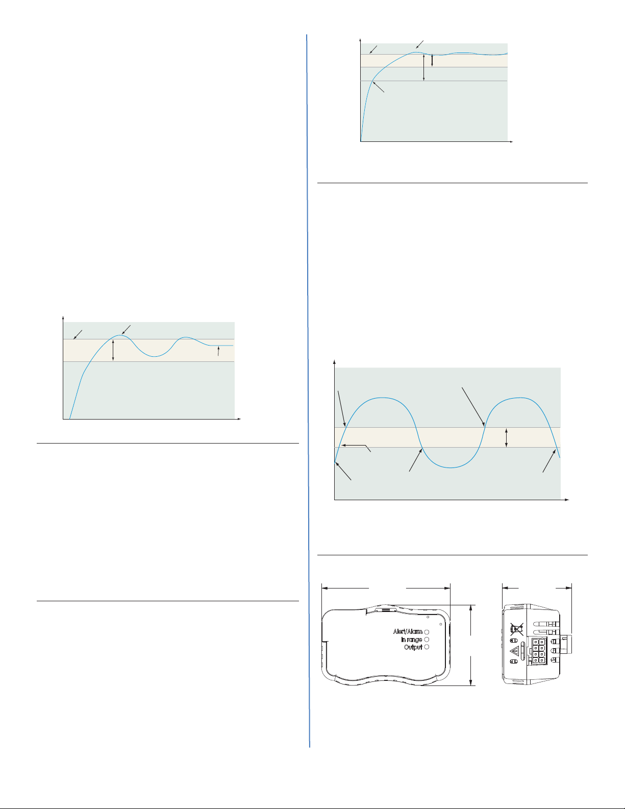
Proportional Control
Some processes need to maintain a temperature or
process value closer to the set point than on-off control can provide. Proportional control provides closer
control by adjusting the output when the temperature
or process value is within a proportional band. When
the value is in the band, the controller adjusts the output based on how close the process value is to the set
point.
The closer the process value is to the set point, the
lower the output power. This is similar to backing off
on the gas pedal of a car as you approach a stop sign.
It keeps the temperature or process value from swinging as widely as it would with simple on-off control.
However, when the system settles down, the temperature or process value tends to “droop” short of the set
point.
With proportional control the output power level
equals (set point minus process value) divided by the
proportional band value.
Adjust the proportional band with Proportional
[`Pb].
Set Point
Temperature
Overshoot
Proportional Band
Droop
Reduced Overshoot
Proportional Band
Proportional Band x 2
Time
PID Control
Temperature
Set Point
Heating Slows
On-Off Control
On-off control switches the output either full on or full
off, depending on the input, set point and hysteresis
values. The hysteresis value indicates the amount the
process value must deviate from the set point to turn on
the output. Increasing the value decreases the number
of times the output will cycle. Decreasing hysteresis improves controllability. With hysteresis set to the lowest
value of 3°C or 5°F, the process value would stay closer
to the set point, but the output would switch on and off
more frequently, and may result in the output “ chattering.” Both the control mode ([Cnt] prompt) and hysteresis ([Hys] prompt) values can be changed either using
the front panel or via Modbus communications.
The heating action switches off when the process
temperature rises above the set point.
Proportional Control
Time
Proportional plus Integral (PI) Control
The droop caused by proportional control can be corrected by adding integral control. When the system
settles down, the integral value is tuned to bring the
temperature or process value closer to the set point.
Integral determines the speed of the correction, but
this may increase the overshoot at startup or when
the set point is changed. Too much integral action will
make the system unstable. Integral is cleared when
the process value is outside of the proportional band.
Integral [Int] is measured in minutes per repeat. A
low integral value causes a fast integrating action.
Proportional plus Integral plus Derivative (PID)
Control
Use derivative control to minimize the overshoot in
a PI-controlled system. Derivative [dEu] adjusts the
output based on the rate of change in the temperature
or process value. Too much derivative will make the
system sluggish.
Set Point
Temperature
Process Temperature
The heating action switches on when the process temperature
The heating action
switches on at startup.
drops below the set point minus the hysteresis.
Time
On/Off System Cycles
Mounting the Series EHG CL
88.8 mm
(3.496 in)
Base Controlller
front
Hysteresis
48.4 mm
(1.907 in)
55.8 mm
(2.196 in)
Base Controller
side
Watlow Controls 6 EHG CL User’s Guide
Page 7
(
(
81.5 mm
(3.210 in)
Interface
side
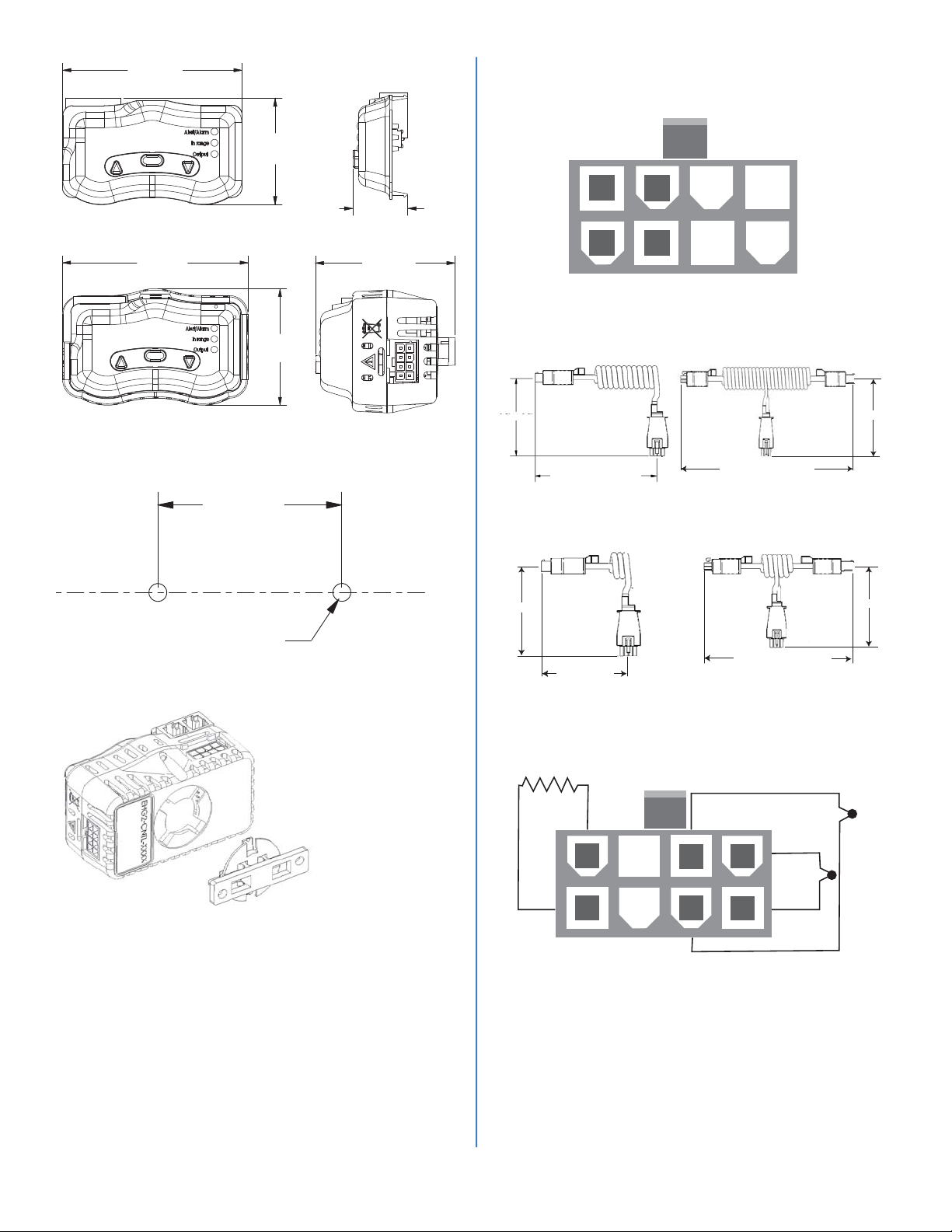
Wiring the Series EHG CL Power, Thermocouple and
Heater Connections
View looking at the top of the controller.
Interface
front
88.8 mm
(3.496 in)
Base Controller with Interface
front
Panel Mount Dimensions
45.72 mm
(1.800 in)
48.4 mm
(1.905 in)
55.8 mm
(2.196 in)
24.7 mm
(0.974 in)
63.6 mm
(2.503 in)
Base Controller with
Interface side
L2
5
1
L2
L1
(black)
6
2
L1
black)
(white)
white)
Power and relay connectors
Control Power Cord Coiled, Terminated Long
Part Number: 4800-0022
3.5” +/- 0.5”
6.0” +/-0.5” relaxed length
>= 18” extended length
Control Power Cord Coiled, Terminated Short
Part Number: 4800-0021
7
3
Control Power Cord Coiled, Jumpered Long
Control Power Cord Coiled, Jumpered Short
8
4
Part Number: 4800-0012
12.0” +/- 1” Relaxed Length
>= 36” Extended Length
Part Number: 4800-0011
3.5” +/- 0.5”
drill and tap for #8-32
Mounting Bracket
The Series EHG CL
mounting bracket lets
you mount the controller in any of four
angles. After disconnecting both wiring
connectors, gently
rotate the controller
counterclockwise until
it unlocks from the
mounting bracket.
Re-orient the controller on the mounting
bracket and gently rotate it clockwise until
it locks.
3.5” +/- 0.5”
3.5” +/- 0.5”
Relaxed Length
7.0” +/- 1” Relaxed Length
With the control facing you this connector is on the
right side.
Heater
Switched
L2
(white)
L1
(black)
– (red)
5
1
6
2
7
3
+ (yellow)
Thermocouple
8
4
Limit
– (red)
Process
Thermocouple
+ (yellow)
Thermocouple and heater connector
3.5” +/- 0.5”
Watlow Controls 7 EHG CL User’s Guide
Page 8
Wiring the Series EHG CL Communications Ports
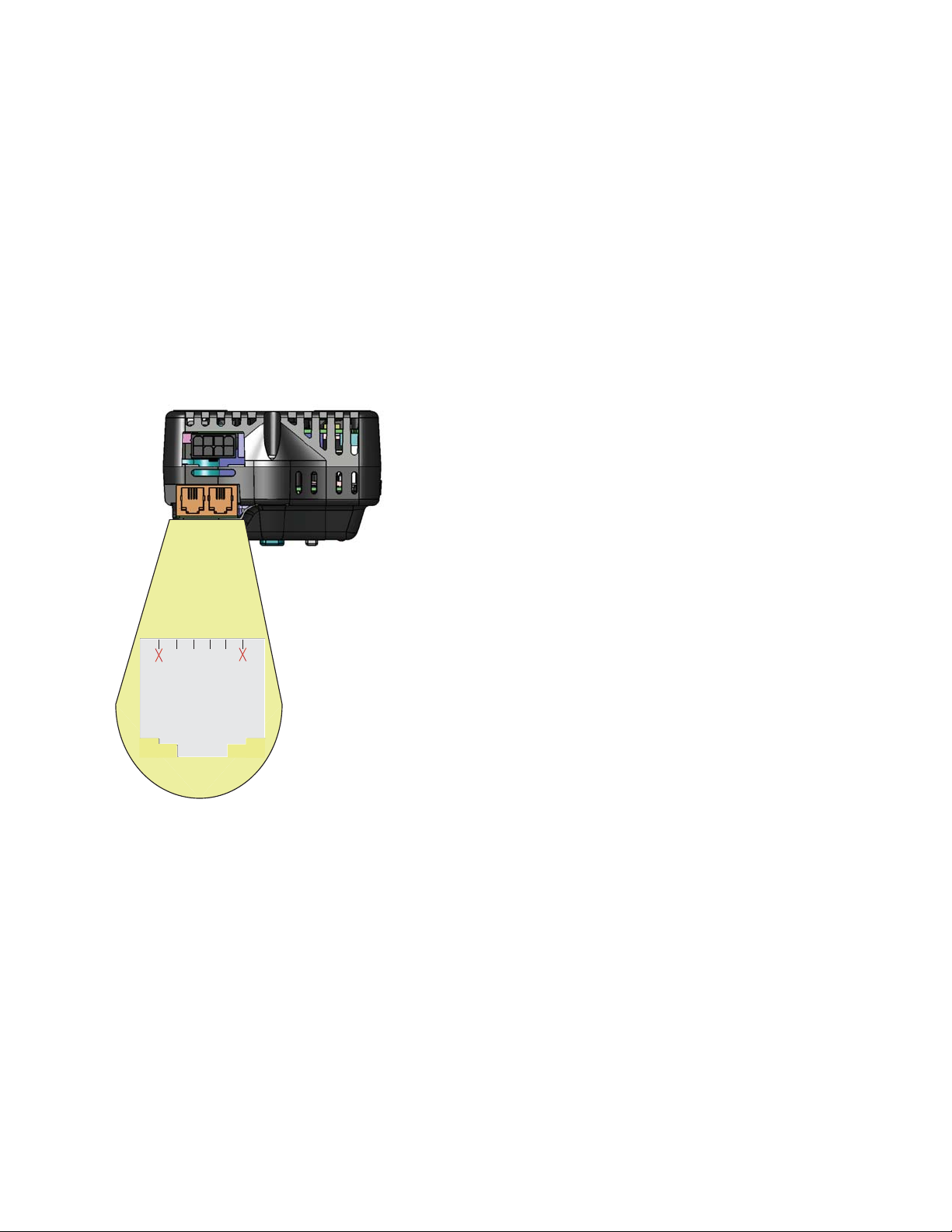
The graphic below reflects the control being held upright
with the display facing the holder. As shown, there are
two jacks on the top of the communications module (RJ45
like, with 4 pins on each) which can accommodate either
a four or six 6 pin modular plug. Communications from
a PC to any EHG CL controller on the network can be
established by connecting it to either of the two available
jacks. The other jack can then be connected to other EHG
CL controllers on the network (32 maximum).
Looking at either of the jacks as shown in the graphic pin
identification is from left to right.
- Left most pin, connects to ground terminal of converter
- Second pin from left, no connection
- Third pin from left, connects to converter A or T- / R-
- Right most pin connects to converter B or T+ / R+
Specifications
Power
• Isolated Universal Power Supply: 85 to 264VÅ (ac)
50/60Hz
• Up to 2400 W with 10A switching capability
NO-ARC Relay
• 10A switching
• 4.5 million cycles
Environmental
• Ambient operating temperature range 0 to 70 °C (32 to
158 °F)
Agency Approvals
• UL® 1998/C-UL
• CE 60730
• SEMI-S2
®
Ordering Information
Series EHG CL Integrated Temperature Controller
- EHG2-AAAA-_ _ _ _ 0 to 537°C (0 to 999°F)
- Display Module - EHG2-CLOO-COMS
- Communications Module - EHG2-CLOO-COMS
- Display with Communications Module - EHG2-CLOO-DSCM
Additional Power Cables
- 4800-0012: jumpered long cable
- 4800-0022: terminated long cable
- 4800-0011: jumpered short cable
- 4800-0021: terminated short cable
1
456
3
Gnd terminal of converter
No connection
A or T- / R-
B or T+ / R+
The Series EHG CL is warranted to be free of defects in material and
workmanship for 24 months after delivery to the first purchaser for
use, providing that the units have not been misapplied. Since Watlow
has no control over their use, and sometimes misuse, we cannot guarantee against failure. Watlow’s obligations hereunder, at Watlow’s
option, are limited to replacement, repair or refund of purchase price,
and parts which upon examination prove to be defective within the
warranty period specified. This warranty does not apply to damage
resulting from transportation, alteration, misuse or abuse.
WARNING:
To avoid damage to property and equipment, and/or injury
or loss of life, use National Electric Code (NEC) standard
wiring practices to install and operate the Series EHG CL.
Failure to do so could result in such damage, and/or injury
or death.
2
Warranty
Watlow Controls 8 EHG CL User’s Guide
Page 9

Declaration of Conformity
Series EHG® CL
WATLOW an ISO 9001 approved facility since 1996.
1241 Bundy Blvd.
Winona, MN 55987 USA
Declares that the following product:
Designation:
Model Numbers: EHG2-AAAA- additional number or letters.
Classification: Electronic Thermostat with Integrated Temperature Limiter Protective Control,
Rated Supply Source: 100 to 240 V~ (ac), 50 or 60 Hz
IP Code IP20
Rated Power: 5 VA Unit power, 10 A Resistive Heater Load
Meets the essential requirements of the following European Union Directives by using the relevant standards
show below to indicate compliance.
Series EHG
Control Relay = 2CK, Limit Relay = 2BJ
Installation Category II, Pollution degree 2, Software Class B
2004/108/EC Electromagnetic Compatibility Directive
EN 60730-1
EN 60730-2-9
EN 61000-4-2 2008 Electrostatic Discharge Immunity
EN 61000-4-3 2010 Radiated Field Immunity
EN 61000-4-4 2011 Electrical Fast-Transient / Burst Immunity
EN 61000-4-5 2006 Surge Immunity
EN 61000-4-6 2008 Conducted Immunity
EN 61000-4-8 2009 Power frequency magnetic field immunity
EN 61000-4-11 2004 Voltage Dips, Short Interruptions and Voltage Variations
EN 61000-4-28 2009 Variation of power frequency immunity – Level 2
EN 61000-3-2 2006 Harmonic Current Emissions
EN 61000-3-3 2005 Voltage Fluctuations and Flicker
SEMI F47 2000 Specification for Semiconductor Processing Equipment Voltage
EN 61010-1 2010 Edition 3 Safety Requirements of electrical equipment for measure-
EN 60730-1
EN 60730-2-9
UL 1998 2008 ED.2 Software in programmable components.
2010
2010
2010
2011
Edition 4 Automatic electrical controls for household and similar use
Edition 4
Edition 3.1
Compliant with 2002/95/EC RoHS Directive
®
CL
– Temperature Sensing Controls, Class B Emissions
Immunity
Sag Immunity – Figure R1-1
2006/95/EC Low-Voltage Directive
ment, control and laboratory use. Part 1: General
requirements
Automatic electrical controls for household and similar use
– Temperature Sensing Controls
Per 2002/96/EC WEEE Directive
Joe M. Millanes Winona, Minnesota, USA
Name of Authorized Representative Place of Issue
Directory of Operations Sept. 2012
Title of Authorized Representative Date of Issue
Signature of Authorized Representative
Please Recycle Properly
Watlow Controls 9 EHG CL User’s Guide
Page 10

How to Reach Us
ER
TISFFAACTCTIIOONN
Corporate Headquarters
Watlow Electric Manufacturing Company
12001 Lackland Road
St. Louis, MO 63146
Sales: 1-800-WATLOW2
Manufacturing Support:
1-800-4WATLOW
Email: [email protected]
Website:
From outside the USA and Canada:
Tel: +1 (314) 878-4600
Fax: +1 (314) 878-6814
Latin America
Watlow de México S.A. de C.V.
Av. Fundición No. 5
Col. Parques Industriales
Querétaro, Qro. CP-76130
Mexico
Tel: +52 442 217-6235
Fax: +52 442 217-6403
www.watlow.com
Europe
Watlow France
Tour d'Asnières.
4 Avenue Laurent Cély
92600 Asnières sur Seine
France
Tél: + 33 (0)1 41 32 79 70
Télécopie: + 33(0)1 47 33 36 57
Email: [email protected]
Website:
Watlow GmbH
Postfach 11 65, Lauchwasenstr. 1
D-76709 Kronau
Germany
Tel: +49 (0) 7253 9400-0
Fax: +49 (0) 7253 9400-900
Email: [email protected]
Website: www.watlow.de
Watlow Italy S.r.l.
Viale Italia 52/54
20094 Corsico MI
Italy
Tel: +39 024588841
Fax: +39 0245869954
Email: [email protected]
Website:
www.watlow.fr
www.watlow.it
Watlow Ibérica, S.L.U.
C/Marte 12, Posterior, Local 9
E-28850 Torrejón de Ardoz
Madrid - Spain
T. +34 91 675 12 92
F. +34 91 648 73 80
Email: [email protected]
Website: www.watlow.es
Watlow UK Ltd.
Linby Industrial Estate
Linby, Nottingham, NG15 8AA
United Kingdom
Telephone: (0) 115 964 0777
Fax: (0) 115 964 0071
Email: [email protected]
Website:
From outside The United Kingdom:
Tel: +44 115 964 0777
Fax: +44 115 964 0071
www.watlow.co.uk
Asia and Pacifi c
Watlow Singapore Pte Ltd.
16 Ayer Rajah Crescent,
#06-03/04,
Singapore 139965
Tel: +65 6773 9488 Fax: +65 6778 0323
Email: [email protected] Website: www.watlow.com.sg
Watlow Australia Pty., Ltd.
4/57 Sharps Road
Tullamarine, VIC 3043
Australia
Tel: +61 3 9335 6449
Fax: +61 3 9330 3566
Website: www.watlow.com
Watlow Electric Manufacturing (Shanghai) Company
1118 Fangyuan Road, Anting Industrial Park, Jiading, Shanghai,
PRC 201203
People’s Republic of China
Tel: +86 21 39509510
Fax: +86 21 5080-0906
Email: [email protected]
Website: www.watlow.cn
ワトロー・ジャパン株式会社
〒101-0047 東京都千代田区内神田1-14-4
四国ビル別館9階
Tel: 03-3518-6630 Fax: 03-3518-6632
Watlow Japan Ltd.
1-14-4 Uchikanda, Chiyoda-Ku
Tokyo 101-0047
Japan
Tel: +81-3-3518-6630 Fax: +81-3-3518-6632
Email: [email protected] Website: www.watlow.co.jp
Watlow Korea Co., Ltd.
#1406, E&C Dream Tower, 46, Yangpyeongdong-3ga
Yeongdeungpo-gu, Seoul 150-103
Republic of Korea
Tel: +82 (2) 2628-5770 Fax: +82 (2) 2628-5771
Website: www.watlow.co.kr
Watlow Malaysia Sdn Bhd
No. 14-3 Jalan 2/114
Kuchai Business Centre
Jalan Kuchai Lama
58200 Kuala Lumpur
Malaysia
Tel: +60 3 7980 7741 Fax: +60 3 7980 7739
瓦特龍電機股份有限公司
80143 高雄市前金區七賢二路189號 10樓之一
電話: 07-2885168 傳真: 07-2885568
Watlow Electric Taiwan Corporation
10F-1 No.189 Chi-Shen 2nd Road Kaohsiung 80143
Taiwan
Tel: +886-7-2885168 Fax: +886-7-2885568
Your Authorized Watlow Distributor
TOT AL
CUCUSSTTOOMMER
SSAATIS
3 Y ear Warranty
Watlow Controls 10 EHG CL User’s Guide
 Loading...