

Page 1

Manual
Installation of WaterWorld
inboard engines
Page 2

Dear reader,
Congratulations on your purchase! We are pleased that you
have chosen a WaterWorld system.
The WaterWorld systems are designed and manufactured
with the greatest care. Everything is aimed at providing you
with a safe, reliable, environmentally sound and userfriendly system that you will enjoy using.
We do everything in our power to constantly improve the
WaterWorld systems.
If you have any comments on the design
or use of the system, we would be grateful if you could let us
know.
You can find our contact details at the back of this
manual.
We recommend that you read this manual carefully so that
you can install and use this system properly. We sincerely
hope you will enjoy it!
Team WaterWorld
3
Page 3

CONTENTS
1. INTRODUCTION
p. 6
6. OPERATION THE ENGINE
p. 34
Using this manual
p. 7
Starting and sailing away
p. 35
Warning and symbols
p. 7
Explanation of the display
p. 36
Serial numbers
p. 8
Arriving and berthing
p. 37
2. PRE INSTALLATION CHECKLIST
p. 10
7. MAINTENANCE AND SERVICE
p. 38
Step-by-step installation plan
p. 11
Inspections during the boating season
p. 39
3. SAFETY
p. 12
Annual checks by you or your supplier
Winter storage
p. 40
p. 41
General guidelines
p. 13
Operating the engine on saltwater
p. 41
Safety devices of the system
p. 14
Safety instructions of the system
p. 15
8. TECHNICAL SPECIFICATIONS
p. 42
Safety instructions for the batteries
p. 16
Engine specifications
p. 43
Safety instructions for use
p. 17
Electric engine
p. 43
Engine controller
p. 43
4. SCOPE OF DELIVERY
p. 18
Control lever
p. 43
Step-by-step plan for installation
p. 19
Relais
p. 43
Display
p. 44
5. SYSTEM INSTALLATION
p. 22
Propeller selection guidelines
p. 44
Connection diagram
p. 23
Positioning of the engine
p. 24
9. ERRORS AND TROUBLESHOOTING
p. 46
Batteries
Battery charger
Cable sizes
Main circuit switch
Main fuse
Relais
Throttle
Display
Ignition switch
Connecting throttle, display and ignition
Setting the display
Adjusting the controller for different
voltages of lithium batteries
Testing and commissioning
p. 26
p. 27
p. 27
p. 28
p. 28
p. 29
p. 29
p. 30
p. 30
p. 30
p. 30
p. 32
p. 33
Error codes for malfunction
Problems
10. WARRANTY
Warranty periods
Warranty conditions
Warranty procedure
ANNEXES
Declaration of conformity
p. 47
p. 49
p. 50
p. 51
p. 52
p. 53
p. 53
p. 54
p. 55
4
Page 4
Using this manual
This manual contains important information for the safe use of the WaterWorld electric drives.
Maintenance
and possible troubleshooting are dealt with in this manual.
It is imperative that any person installing this system, as well as anyone operating the engine, familiarize
themselves with the manual and carefully follow and implement the warnings and safety instructions
contained herein.
Installation and maintenance of WaterWorld engines must be carried out by specialised and skilled installers
who are aware of the applicable laws and regulations in combination with the safety aspects mentioned in this
manual.
Keep this manual with your system in a safe and easily accessible place!
Warnings and symbols
DANGER
A warning signifies the risk of possible injury to the user/installer or of
substantial material damage if the user or installer does not avoid the risk.
WARNING!
Special data or commandments and prohibitions with regard to damage prevention.
ATTENTION!
Instructions that deserve extra attention and must be followed.
1.
INTRODUCTION
Using this manual
Warning and symbols
Serial numbers
6 7
Page 5
Serial numbers
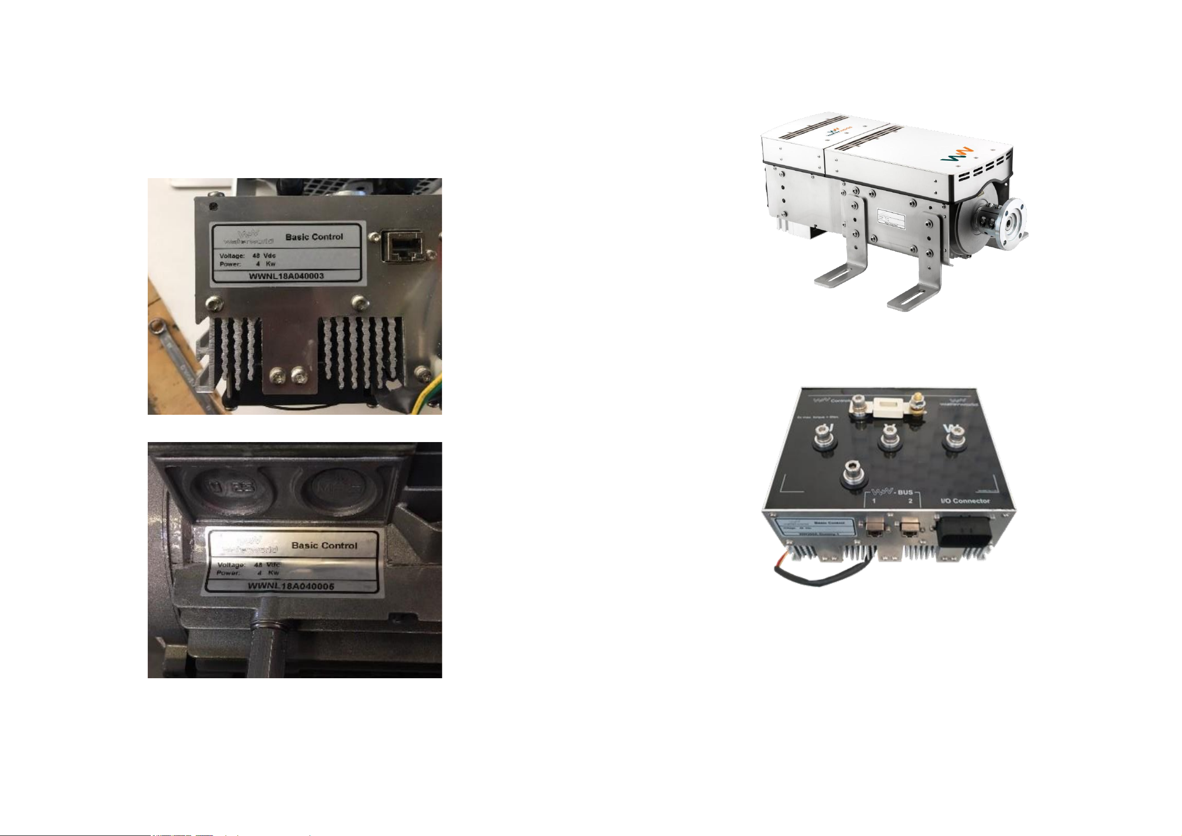
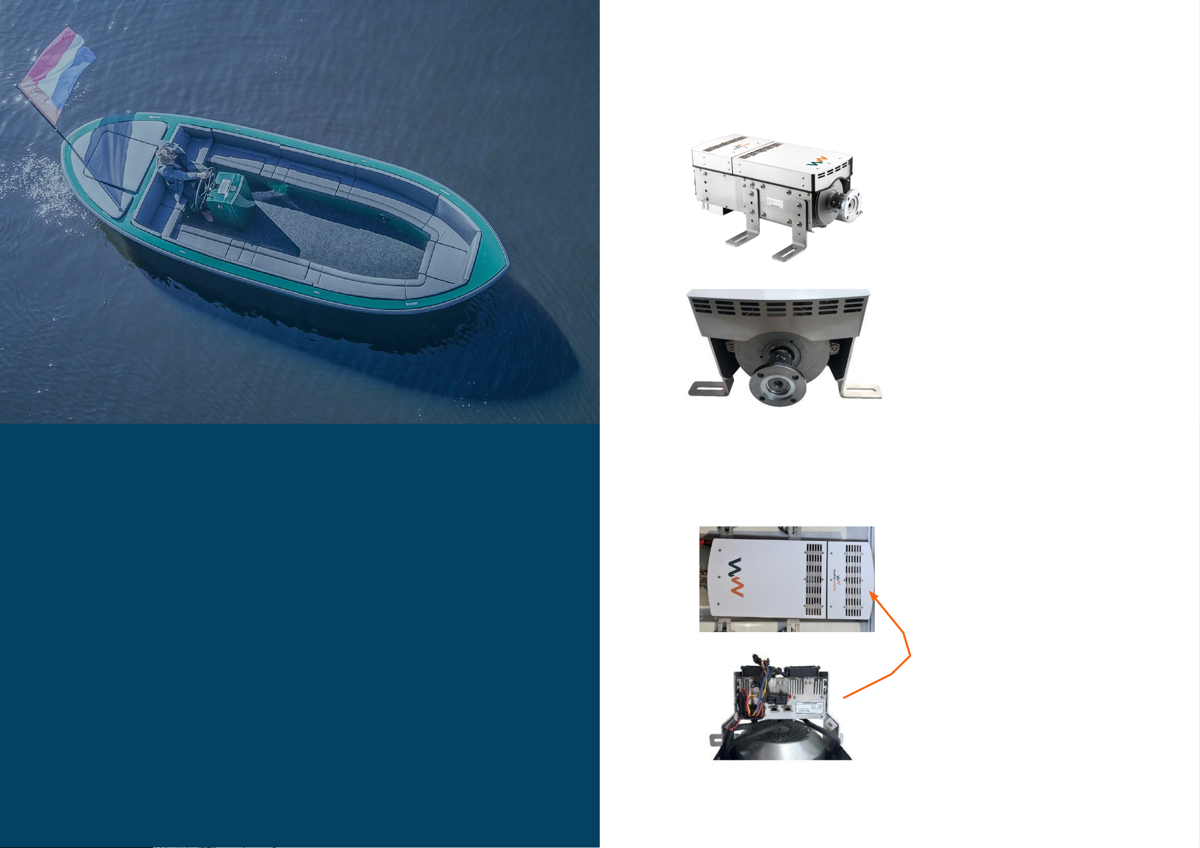
You will find the identification label with the serial number on the top of the motor controller and on the side
of the engine. It shows the manufacturer, the type number and the unique serial number of the
motor/controller. The serial number starts with the letters WW.
Engine
Motor controller
ATTENTION! Never remove the identification labels and/or other stickers on the engine.
8 9
Page 6
Step-by-step plan for installation
1.
Read the manual.
We offer you a manual that is as complete as possible. This includes items that are not related to the
WaterWorld engine, but to the whole boat, the propeller and the batteries. However, each
installation is customised and must be installed by a competent person.
2.
Check that you have received everything included in the scope of delivery.
See page 18. Lay everything out clearly and compare it with the list in chapter 4 of this manual and your
packing list. If you have any questions, please contact your supplier immediately.
3.
Prepareer de boot om in een schone en droge omgeving het systeem aan te kunnen leggen.
If the following points are not in order, they must be rectified before installation.
• No permanent bilge water where the engine is installed.
• Good protection against flooding of the boat, such as a functioning bilge pump in the right place in the
boat.
• When installing components, also consider leakage or condensation from above. For this reason, a
component may have to be placed somewhere else or covered from above.
• Ensure that the space or spaces in question are well ventilated so that moisture can evaporate and leave
the area.
• WaterWorld has developed a highly efficient motor that can do without air cooling. It is very important,
however, that sufficient cold air can enter and hot air can be released.
• A smooth-running propeller shaft system. A badly running propeller shaft system will cause the following
problems:
•
Higher consumption, resulting in shorter sailing time
•
Overheating of the engine
•
Reacting to acceleration
•
Less throttle control, the engine will start with too much capacity once it has enough power
4.
Choose the right propeller.
Please see our advice on page 44.
5.
Check the accessibility of the components.
Will all components be accessible in the future so that everything can be serviced?
PRE-INSTALLATION CHECKLIST
Step-by-step installation plan
6.
7.
8.
9.
10.
Ensure good weight distribution in the boat.
The (lead) battery pack is heavy, ensure proper weight distribution in the boat. Make sure that the batteries
are accessible for servicing the battery poles, wiring and, in the case of wet batteries, filling them with
distilled water.
Choose the right thickness of cabling.
For cable selection, see page 27. Ensure that cable lengths are not unnecessarily long where this can be
prevented.
Read the safety instructions in chapter 3 before you start to connect anything.
Then read the section of the manual concerning that component. Always connect according to the connection
diagram on page 23.
Start installation.
Complete the online checklist.
In order to ensure the proper functioning of the system, the checklist in the Annex must be completed online
at www.ww-el.com
10 11
Page 7
3. SAFETY
General guidelines
Safety instructions for the batteries
Safety instructions for use
General guidelines
• The drive must be operated at the prescribed voltage.
• In the standard setting, this is 48 Volt nominal. Minimum 42 Volts, maximum 60 Volts.
• There is a special setting for 12 cell series lithium batteries operating at a lower nominal
voltage of 44 Volts, this setting is 37 Volts minimum, see page 25.
• The drive is intended exclusively for driving boats. The manufacturer cannot be held liable for any
other use and the warranty will lapse in all cases
.
• Keep the electronics away from water.
• Installation and repair may only be carried out by an approved installer designated by WaterWorld
.
• Only use original or recommended WaterWorld accessories and spare parts.
• If the drive must be repaired, only original replacement parts may be used. The use of non-
original parts may lead to serious injury or damage and void any further warranty.
• Replacing the batteries may only be done by a authorised installer.
• The user must regularly check that the drive and the batteries are functioning correctly. The
manufacturer is not liable for any damage resulting from the incorrect operation of the drive.
• The supplier, whether WaterWorld, the seller or the manufacturer, disclaims any liability for any
damage suffered by the buyer or any third-party claims resulting from (the use of) the drive, whether
direct or indirect and / or consequential damage, environmental, hearing, business and intangible
damage, or incorrect advice, unless the damage is due to gross negligence or misconduct on the part
of the supplier
.
• Before use, you should take into account the legislation in the respective country, or at the location
where the drive is located. The purchaser is hereby responsible for complying with all precautionary
measures, legal or otherwise, at the location where the drive is used, regardless of whether the drive
is operational at the time. This includes measures for fire safety and the safety of others in the
vicinity of the drive
.
• The manufacturer reserves the rights and authority to which it is entitled under European
legislation. Reproduction or imitation of the device is expressly forbidden.
• For other battery packs, e.g. lithium batteries, please contact your supplier in advance
.
13
Page 8

Safety devices of the system
Your WaterWorld system is equipped with various safety devices:
WARNING!
Safety instructions for the system
Follow the instructions in this manual
• In the event of overheating, smoke development or as soon as you recognise
a fault, switch the system off immediately at the main switch.
DANGER
• Over-temperature protection in engine and controller: The engine will reduce its power if the
electronics detect too high temperatures
.
• Fuse regulator: Varying according to motor power, a fuse is placed on the motor regulator.
• External fuse cabling: It prevents fire/overheating or overloading of the system. This external fuse
is
not
included in the standard delivery scope, but must be installed
.
• Main switch: Always switch off the main switch when leaving the boat or when working on the
system. Not included in the system as standard.
• Battery overload protection: If your batteries are running low, the engine will automatically
reduce power, allowing you to cruise longer and reach a safe harbour at low speed.
• Ignition key: Use this to switch off the system if there is any danger. Always switch it off when there
are swimmers around the boat
.
• Display: This continuously shows you the remaining sailing time so that you can plan your trip
to reach your destination. In addition, the display warns of a too high or too low battery voltage.
The low voltage warning is also given by an acoustic signal and an indication on the screen.
• Power cables connecting the motor, the controller and other components must be checked
regularly for damage or breakage and for correct, firm fastening.
• The terminal lugs of live cables to which the motor, the controller and other components are
connected must have terminal caps that also cover the battery terminals.
• If damage or breakage of the cables / wires is detected, the motor must be taken out of service
immediately until the cable / wire in question has been replaced.
The allowed ambient temperature during operation must not be lower than
-20 degrees Celsius and not higher than 50 degrees Celsius.
• Do not touch the drive shaft, engine and battery parts during or immediately after sailing.
• Always switch the system off at the main switch during installation and dismantling work.
14 15
Page 9

Safety instructions for the batteries
Observe all safety instructions concerning the batteries used in the battery
manufacturer's operating instructions.
DANGER
Safety instructions for use
Read this manual thoroughly.
• The WaterWorld system may only be used by persons who are qualified and physically and mentally fit to do
so.
• Do not use the WaterWorld system if the battery is damaged and inform the system supplier or
installer
.
• Do not store flammable items near the battery.
• Never smoke- and avoid sparks or flames in the vicinity of the batteries.
• Have plenty of water available; if battery acid comes into contact with the skin or eyes, flush
immediately with water and get medical attention.
• Only use charging cables suitable for outdoor use.
• Always unroll the reel of a 230V socket completely when using it.
• Avoid strong mechanical forces on the system's batteries and cables.
• Take off metal jewellery and watches before starting work on or near batteries and use
insulated tools for this purpose.
• Never short-circuit the battery. Make sure that tools and metal objects never touch the
battery. This may cause sparks or even an explosion or fire.
• When connecting the battery, ensure correct polarity and that the connections are firmly
attached and make good contact.
• Battery poles must be clean, corrosion-free and covered with terminal caps.
• Do not place batteries in an insufficiently ventilated area. When batteries are placed in a box, the
proper ventilation must be present
.
• Connect only identical batteries (type, capacity, age and charge status).
• Connect only batteries with identical state of charge.
• Make sure that the battery terminals always make optimum contact with the cable lugs that
are connected to them.
ATTENTION! Always ensure that there are no stainless steel rings between the battery terminal and
the connected cable.
• Always observe the national regulations and rules of a country.
• Keep the drive and controls out of the reach of children and persons with limited capabilities.
• Have the operation and safety provisions of the entire system explained to you by the shipyard
or installer.
• Check the system for mechanical damage before departure.
• Check the condition and operation of all functions of the WaterWorld system at the start of each
voyage at low speed.
• Only sail with a system that is in a technically perfect condition.
• Make sure the batteries are sufficiently charged.
• Make sure you are familiar with all the controls of the WaterWorld system. You should also be
able to stop the system quickly if necessary.
• As the pilot of the boat, you are responsible for the safety of those on board and of all boats
and persons in your vicinity. Therefore, please observe the basic rules of boating behaviour.
• Special care must be taken when there are persons in the water, also when sailing at slow speed.
• Before setting off, find out about the area where you will be sailing and take account of the
weather forecast and sea conditions.
• Plan enough reserve for the necessary range.
• Depending on the size of the boat, make sure that the specific safety equipment is available and accessible
(life jackets, anchor, paddle, communication equipment, etc.).
16 17
Page 10
Contents WaterWorld package
WaterWorld systems are supplied as standard with
4.
SCOPE OF DELIVERY
Contents WaterWorld package
Engine
Secured in a stainless steel frame
Thrust bearing
Integrated in the engine, shaft fitted with
a flange for attaching a counter flange
(not supplied) to the propeller shaft (not
supplied).
Cotroller
Mounted in the same frame (can also be
supplied separately). Motor and controller
are already connected by cables.
18 19
Page 11
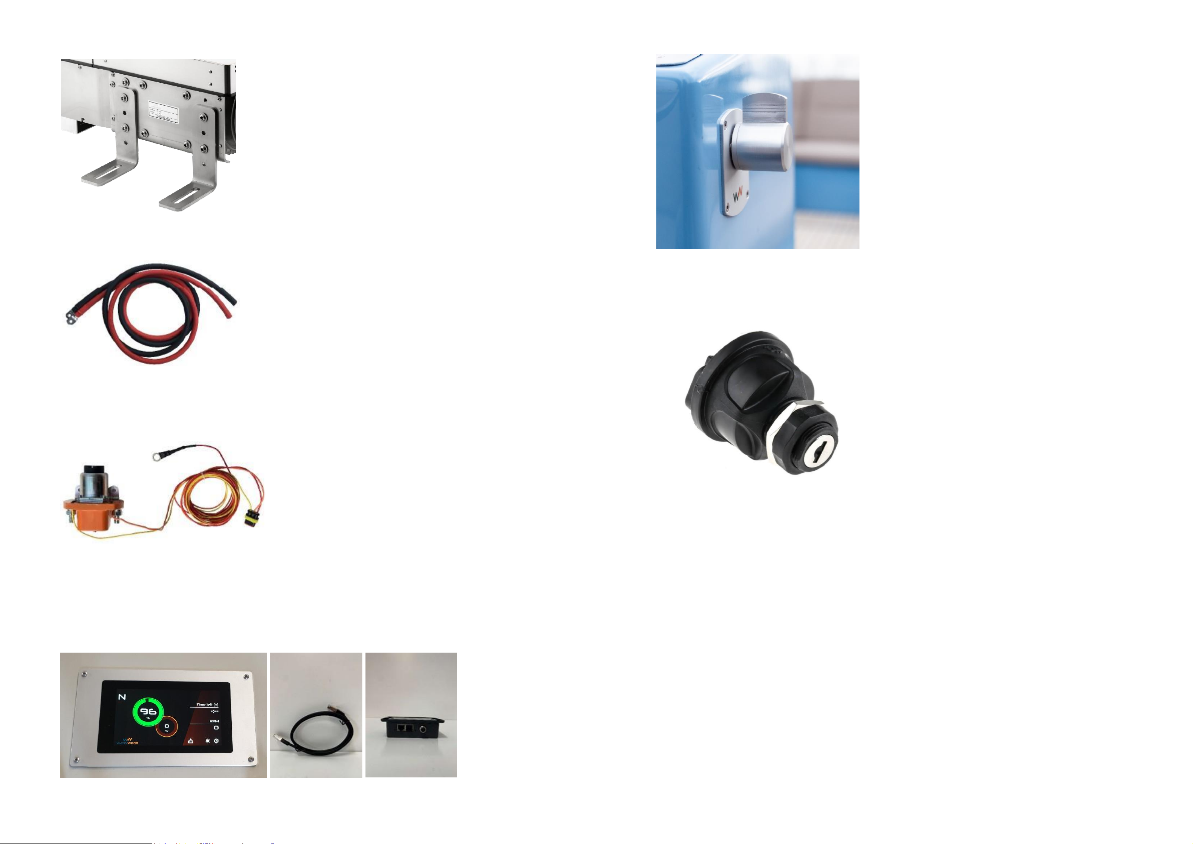
Engine mounts
Variable attachment to the outside of the
frame
.
ATTENTION!
During installation, the supports
are turned over and the motor will hang in them
instead of standing on them.
Power cables
of 0.5 (plus) and 1.0 metres (minus)
already connected to the controller.
48 Volt Relais
The amperage depends on the selected
motor power.
Digital display
RJ45 2 x data cable (1 m. en 3 m.) and gateway
Throttle
Throttle and RJ45 data cable 3 m.
Dashboard with ignition switch
ATTENTION!
Not included in the standard scope of supply are vibration absorbers, fuse with fuse holder for
the battery cables, main switch and battery pack with charger
.
20 21
Page 12
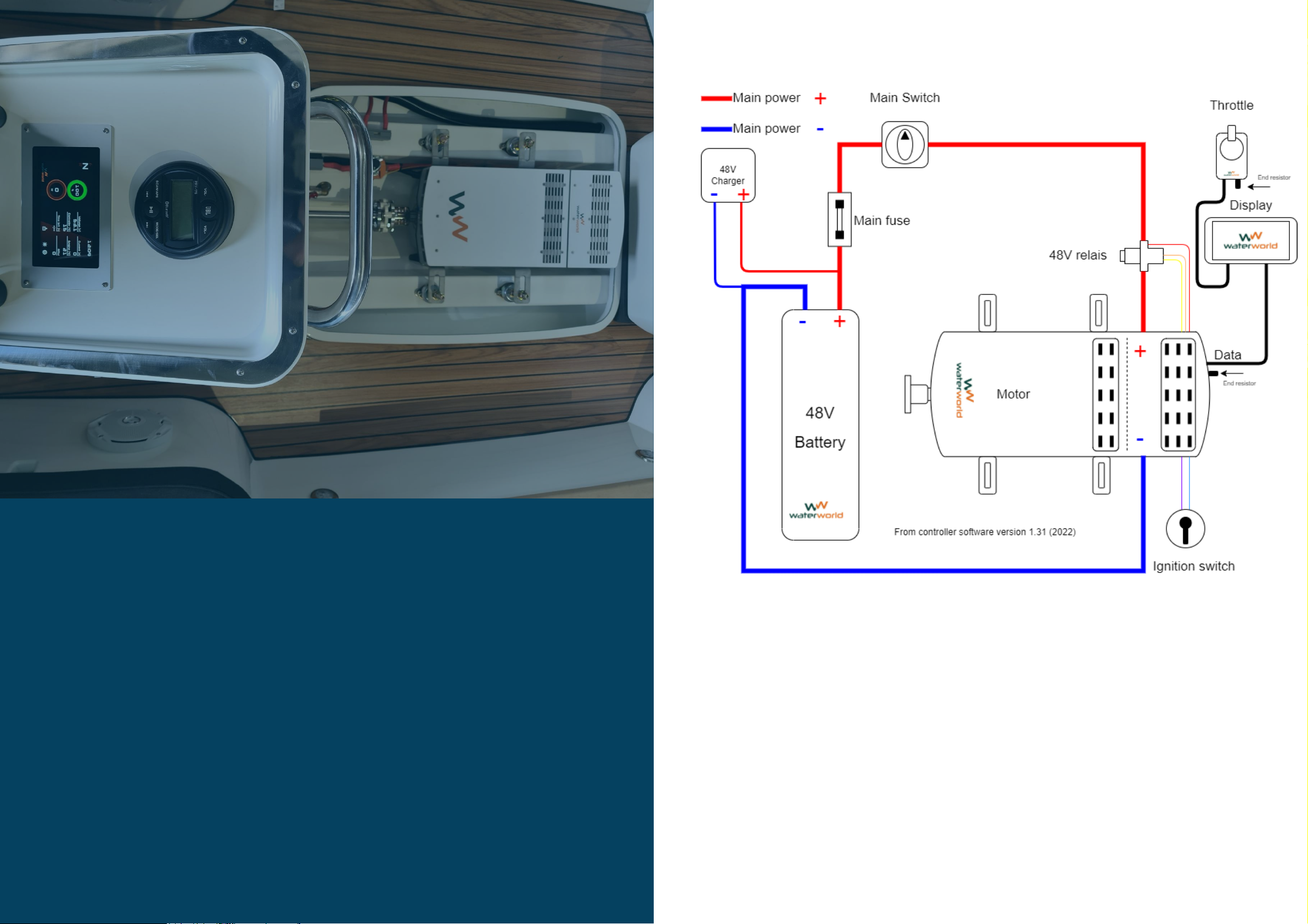
Connection diagram
5.
SYSTEM INSTALLATION
Placement of the engine
Batteries
Battery charger
Recommended cables
Main circuit switch
Main fuse
Relay
Connection diagram
The Shunt
Display
Throttle
Setting the display
Testing and commissioning
22
23
Page 13
Placement of the engine
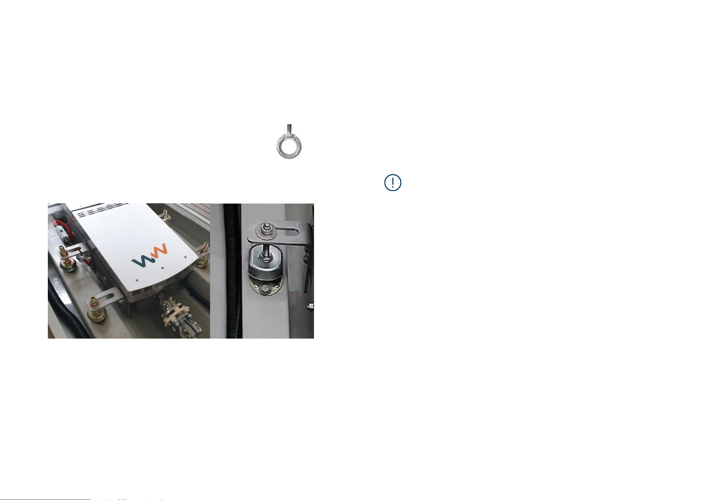
The WaterWorld drive can best be installed using the following step-by-step plan.
1. Remove the engine covers and carefully store them in a safe place.
2. Mount the engine on a foundation and vibration dampers that are suitable for absorbing the system's
thrust and transferring it to the boat.
ATTENTION! Should you choose to mount the engine without vibration dampers, it is very important
that the engine is very well aligned with the shaft. Even if you do use a flexible coupling. In
addition, this can lead to extra noise, especially in aluminium boats.
ATTENTION! Given its weight, it is best to lift the WW 7.5 or 10.0 into
the boat. To do this, screw the lifting eye supplied (see illustration on
the right) into the top of the motor where it is threaded. You can then
lift and lower the motor using a hoist..
3. The side supports on the engine are delivered with the supports pointing downwards. In most cases,
these have to be turned around and the engine will hang in the supports as in these two pictures:
5. The WaterWorld controller comes with 2 metres of red and black battery cable already fitted to the
motor controller side. The red cable on the + side is connected to the relay
.
6. We recommend and use the following cable thicknesses:
4.0kW 35mm2
7.5kW 50mm2
10.0kW 50mm2
If you are going to use cable lengths longer than 5 metres, we recommend using thicker cabling.
7. The engine and controller are cooled by fans: two at the back of the drive (visible from the front of the
system) and one on the engine. Make sure that there is free airflow to dissipate the heat. The air is sucked
in at the front of the motor case or room and discharged at the back. If necessary, air vents should be
installed to allow fresh air to enter and hot air to leave.
Waterworld takes no responsibility for loss of performance, damage
or other problems caused by inadequate ventilation of the system
.
WARNING!
8.
.
In the standard version, the engine and controller are in one frame and these components are already
interconnected at the factory. So there is no need to do anything else. If there is not enough room for the
controller directly behind the motor, or if batteries are installed above the motor, you can install the
controller separately at another place in the boat. To do this, it can be removed from the frame, and the
rear part of the frame on both sides can also be removed.
The phase cables may be up to 50% longer than
at the factory. Always ask an expert
.
ATTENTION If you want to install the controller externally from the engine, this must be done in
consultation with WaterWorld by a certified installer
!
4.
Preferably use a flexible rubber coupling between the engine flange and the propeller shaft. This
prevents vibration in the boat and compensates for imperfections caused by the quality of the
propeller shaft system or the alignment of the propeller shaft..
ATTENTION! If the propeller shaft is mounted directly on the engine with a rigid connection, the
engine must be very well aligned to avoid damage to the electronics and connectors. Never hit the
propeller shaft with a hammer, this can damage the bearings in your engine! Always use a pulley
to disassemble the propeller.
ATTENTION! With a WW 7.5 and 10.0 engine in a heavy vessel, or professional use with many
hours of sailing, it is advisable to use an external thrust bearing, so that the rubber engine mounts
and the thrust bearing in the engine are not overloaded in the long run. If you have any doubts,
please contact your supplier.
24 25
Page 14
Batteries
ATTENTION! Ensure that there is never any power to the system during
installation and assembly!
The drive operates on 48 Volts. Provide a battery pack that is suitable for this application in terms of
quality and capacity. Use traction, semi-traction - deep cycle, or lithium batteries that meet the
specifications.
ATTENTION! When in doubt about the specifications of lithium batteries, it is advisable to consult
WaterWorld. It
It is possible that the batteries may damage the engine, or vice versa if the two are not compatible..
1. Position the batteries in the vessel in such a way that:
a. the weight is well distributed and the boat lies nicely on the waterline.
b. the batteries cannot move in the boat after installation.
c. the batteries are accessible for connection of the cables and for further maintenance work.
d. the batteries do not interfere with the daily use of the boat.
e. Cabling to the engine and to the charger is easily possible without unnecessary cable length
2. Check the individual voltage of all batteries and make sure that they are within 0.1 Volt of each other
before connecting them. If this is not the case, all batteries must be charged individually.
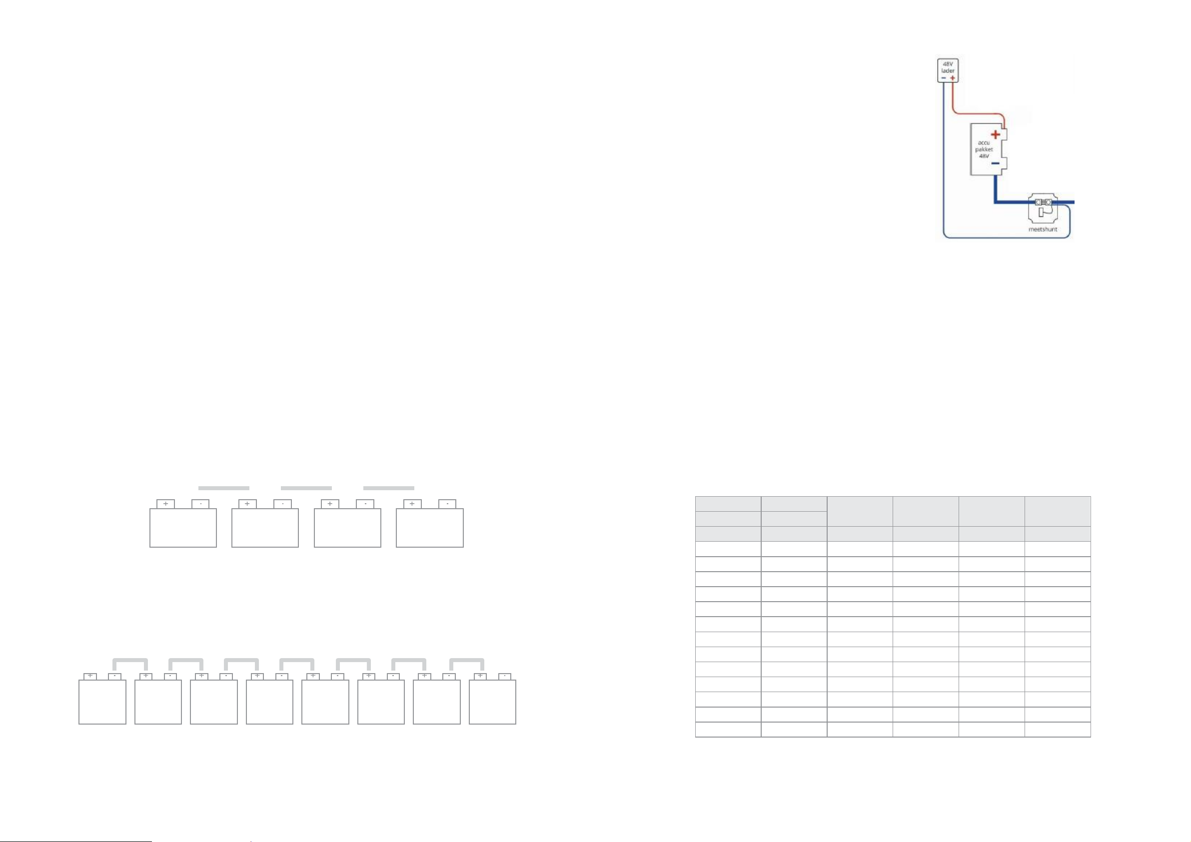
Connect the batteries in accordance with the applicable diagram.
Below are examples of 4 x 12 Volt batteries in series and 8 x 6 Volt batteries in series.
Connecting with 12V batteries
+ -
Connecting with 6V batteries
+
-
ATTENTION! Wait with connecting the batteries to the rest of the system until everything is connected properly.
Battery charger
The battery charger must be selected for the
battery pack and be adequate in terms of voltage,
charging capacity in amperes, battery type and use
in a boat.
ATTENTION! When positioning the charger, think
about the same issues as with the engine and
batteries. Moisture, accessibility, cabling,
ventilation, etc.
Recommended cables
Waterworld 4.0: up to 4.4 kW input power, max. 92 Amps.
For a 4.0, a cable thickness of 35 mm² is recommended.
Waterworld 7.5: up to 8.25 kW input power, max. 172 Amps
.
For a 5.0, a cable thickness of 50 mm² is recommended.
Waterworld 10.0: up to 11 kW input power, max. 230 Amps.
For the 10.0, a cable thickness of 70mm² is recommended.
WaterWorld 15.0: up to 20 kW input power, max 400 Amps.
For the 15.0, a cable thickness of 95mm² is recommended.
The above information is based on cable lengths up to and including 5 metres, for further advice for shorter and
longer lengths please refer to the table below
.
cable
cable
L(+) + L(-)
≤ 5 meter
L(+) + L(-)
≤ 10 meter
L(+) + L(-)
≤ 15 meter
L(+) + L(-)
≤ 20 meter
diam
section
mm mm
2
I max A
I max A
I max A
I max A
0.98 0.75 2.3 1.1 0.8 0.6
1.38 1.5
4.5 2.3 1.5
1.1 1.78 2.5 7.5
3.8 2.5 1.9
2.26 4 12 6 4 3 2.76 6 18 9 6 5
3.57 10 30 15 10 8
4.51 16 48 24 16 12 5.64 25 75 38 25 19 6.68 35 105 53 35 26 7.98 50 150 75 50 38 9.44 70 210 105 70 53 11.00 95 285 143 95 71
12.36
120 360 180 120 90
Battery cable selection; maximum current with a voltage drop of 0.259 Volt. The voltage losses across the
connection contacts have not been taken into account. The total cable length from the + to the - terminal
must be included.
26 27
12 Volt
12 Volt
12 Volt
12 Volt
6 Volt
6 Volt
6 Volt
6 Volt
6 Volt
6 Volt
6 Volt
6 Volt
Page 15
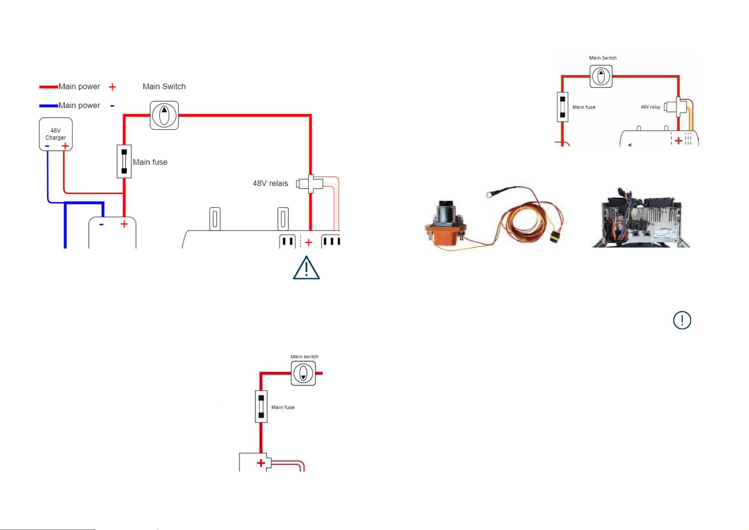
Main switch
Install the main power switch in an easily accessible place in the (red) + cable between the motor
controller and the batteries, so that in case of emergency or maintenance the system can be easily
disconnected from the batteries..
Relais
Install the supplied relay in the (red)
+ cable, between the motor and the main
power switch.
The loose red cable with M8 eye connects
to the relay bolt on the battery side. Make
sure that this red cable is well connected,
as a bad connection can lead to engine
failure when starting the engine.
The relay has a plug with 3 wires, which is
connected to the controller on the mating
plug. This has the same colour wires and
fits only one way.
Once the system is installed, make sure the main switch is always OFF (“0” or “off”
position)when working on the components and when disconnecting the power
cables.
Throttle
DANGER
ATTENTION! The main switch must be switched off when charging the batteries.
Main fuse
Mount the main fuse between the main power switch and
the + pole of the batteries, as close to the battery as
possible, preferably in the battery compartment.
1. Mount the throttle in the appropriate place, well accessible to the driver.
Ensure that the throttle is mounted in such a way that the boat's crew cannot
easily bump into it, causing sudden departure or acceleration!
2. Fit the throttle in such a way that, in the neutral position, the throttle is
vertical.
WARNING!
Make sure that this main fuse is inside the boat, but
remains visible by opening a hatch. The capacity of the
fuse in amperes should be about 1.6 times the maximum
amperes of the engine (see specifications).
You can order an ANL fuse holder + ANL fuse with the
system. We supply the following values:
WaterWorld 4.0 kW
–
160A
WaterWorld 7.5 kW
–
250A
WaterWorld 10.0 kW
–
325A
Waterworld 15.0kW - 600A
ATTENTION! The throttle is set as follows by default: moving the lever clockwise moves the boat forward,
moving it anti-clockwise moves it backward.
This is the correct position when the lever is mounted on the starboard side of the steering console.
If you want to use the lever differently, the phase cables can be reversed. See also the instructions for
setting the display. This should only be done by an authorised dealer or installer.
28 29
Page 16
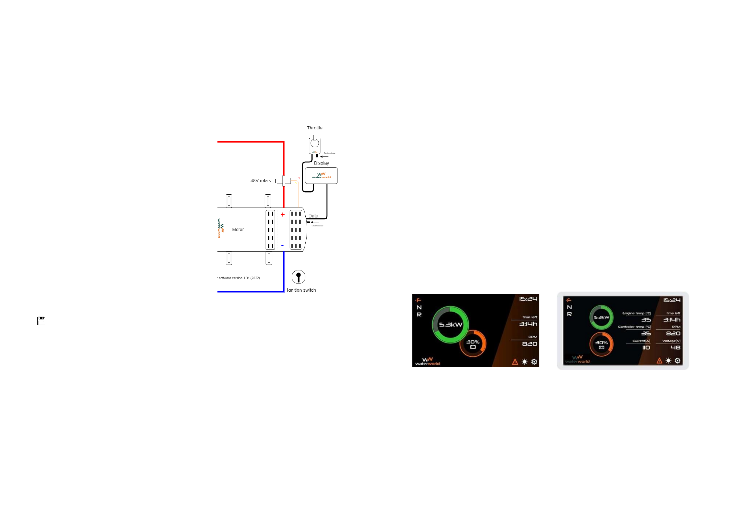
Display
1. Mount the display in the appropriate place. It should be clearly visible to the driver of the boat.
2. Mount the Gateway close to the display, but in an indoor area, e.g. on the inside of a console.
Ignition switch
Mount the ignition lock in the appropriate place, well accessible to the driver, for example next to the display
or under the throttle.
Connecting throttle, display and ignition switch
1. Connect an RJ45 cable from the display to the
controller.
2. Connect a RJ45 cable from the throttle to the
display.
3. Connect the plug of the ignition switch to the
controller.
Control
Mounting side:
1. Right-handed propeller + right-hand throttle = do not adjust anything
2. Right-handed propeller + left-hand throttle = display setting + change phase cable
3. Left-handed propeller + right-hand throttle = change phase cable
4. Left-handed propeller + left-hand throttle = display setting
Reduce power warning
Here you can set the maximum power for a number of minutes. This is useful, for example, if you want to reduce
the power after a few minutes to save the batteries. It can also be used with the WW 15.0, which can temporarily
deliver up to 20 kW of power, if the battery pack allows it. Consult your supplier if necessary
.
Display
Main screen
The screen default setting is "Basic". Here you can see all information needed for standard operation. For
"Basic" display see image below left.
The screen "advanced" mode, you can see more information that is not required for standard operation. For
“Advanged” display see image below right
.
Display time
Here you set the time and time zone. CAUTION: first set the date and then the time. Under the heading
display you can determine whether the time is visible. Changing from summer time to winter time and vice
versa is automatic.
System information
Here you can see the software version of the display, the controller and the serial number of the display. If CAN
communicating batteries are connected, the customer ID is also displayed here.
.
Setting the display
To get started, tap the settings icon in the lower right corner of the screen. NB: after completing each step, press
to save the values! Then scroll through the different settings:
Battery
Mode: Select: “stand alone” (in most situations) or “can bus” for some brands of lithium batteries
(contact your supplier for this).
Low voltage:
Set the voltage at which you want the message drive slowly; for lead-acid batteries (AGM) this is
usually 44V. Consult your supplier on this if required
High voltage: Enter the voltage of a 100% charged battery; see battery specifications. Quality: Enter the
percentage of aging. This can be taken from the battery's specification, which states an aging rate per year,
or from a test by your dealer.
C value: Fill in the C values of the battery according to specifications; complete them all!
For lead-acid batteries: Does your battery manufacturer only give a C20 and C5 value? Then at C10 fill in the
average of C5 and C20 and at C1 fill in half the C5 value..
Example:
C20 = 400 Ah
C10 = 350 Ah (between C20 and C5) C 5 = 300
Ah C 1 = 150Ah (50% of C5 value)
For lithium batteries: all values equal to the C1 value.
Basic screen
Advanced screen
ATTENTION! The display has its own battery, which must be replaced every 5 years
30 31
Page 17

Adjusting the regulator for different voltages of the lithium battery
It is possible to use the WaterWorld motor with a 12 cell serial lithium NMC battery pack. To do this, a setting
in the controller must be changed
.
If the plug with the green/black cable is not connected, the system is suitable for standard voltages.
The cut-off voltage, the minimum voltage below which the regulator stops working, is 42 V.
1.
2. If the green/black cable is connected, the "cut-off" voltage, the minimum voltage below which the
regulator stops working, has been reduced to 37V.
ATTENTION!: Many lead-acid batteries go up to a load of 37V.
Setting 1
Suitable for: AGM and semi-traction lead-acid batteries, 2x Torqeedo Power 24-3500 batteries in series and
Aces lithium batteries.
Setting 2
Suitable for lower voltages can be used with the Torqeedo Power 48-5000 battery and full-traction batteries.
Also some AGM batteries are suitable for this setting
.
ATTENTION!
If this mode is used improperly, it can lead to irreparable damage to the battery pack.
WaterWorld assumes no responsibility for damage caused by excessive discharge
.
Testing and commissioning
To check the operation of the system after installation, please proceed as follows:
• Check whether the batteries are sufficiently charged by measuring the voltage at the terminals
of the battery pack with a multimeter. The total voltage should be at least 48 Volts, but around
52 Volts is to be expected. With lithium batteries this can be up to almost 60 Volts.
•
ATTENTION!
Before connecting, always check that all batteries have the same voltage, maximum
difference is 0.1 Volt
.
• Check that the ignition switch on the dashboard is off
• Check that the throttle is in the neutral position
• Turn the main switch to "on" or I
• Turn the ignition switch clockwise to switch the system on, you will hear a clear click of the relay switching
on.
• Check if the display is on. In the advanced setting of the display you can also see the voltage, does this
correspond with what you measured?
• Gently open the throttle and check if the engine works correctly in both forward and reverse.
• Check that the display shows a certain number of kW when accelerating
• Return the throttle to the neutral position.
•
ATTENTION!
Check the engine and controller temperature in the dashboard. Is it approximately the
same as the engine compartment temperature (engine and controller temperatures are never exactly
the same).
• Turn off the ignition
• Turn off the main switch
• Connect the shore power cable
• Check that the charger starts and gives the right signals. Refer to the charger's manual.
• Check on the display whether the voltage of the battery pack goes up to the specified charging voltage.
Consult the manual of the battery pack for this.
• Preferably charge the battery pack fully before the first trip and before setting up the display. See
explanation of the use of the display below.
• Make a sea trial and check everything visually, also pay attention to sounds and vibrations.
• During the sea trial, check the number of revolutions (rpm) at full throttle and the maximum engine power at
full throttle (kW) to determine whether you have the right propeller.
• Max RPM should be 1400-1500.
• Max power should be 100% to 110
32 33
Page 18
Starting and sailing away
1.
ATTENTION!
First disconnect the shore power.
2. Check that the ignition switch in the dashboard is off.
3. Check that the throttle is in the neutral position.
4. Make sure you have clearance to move away, or that the boat is securely tied up to test the system.
5. Turn the main switch to on or I.
6. Turn the ignition switch clockwise to turn the system on.
7. Check that the display turns on and shows the correct information.
8. Gently open the throttle.
9. Check that the throttle lever operates correctly in neutral, forward and reverse.
.
6. OPERATION THE ENGINE
Starting and sailing away
Explanation of the display
Arriving and berthing
34 35
Page 19
Explanation of the display
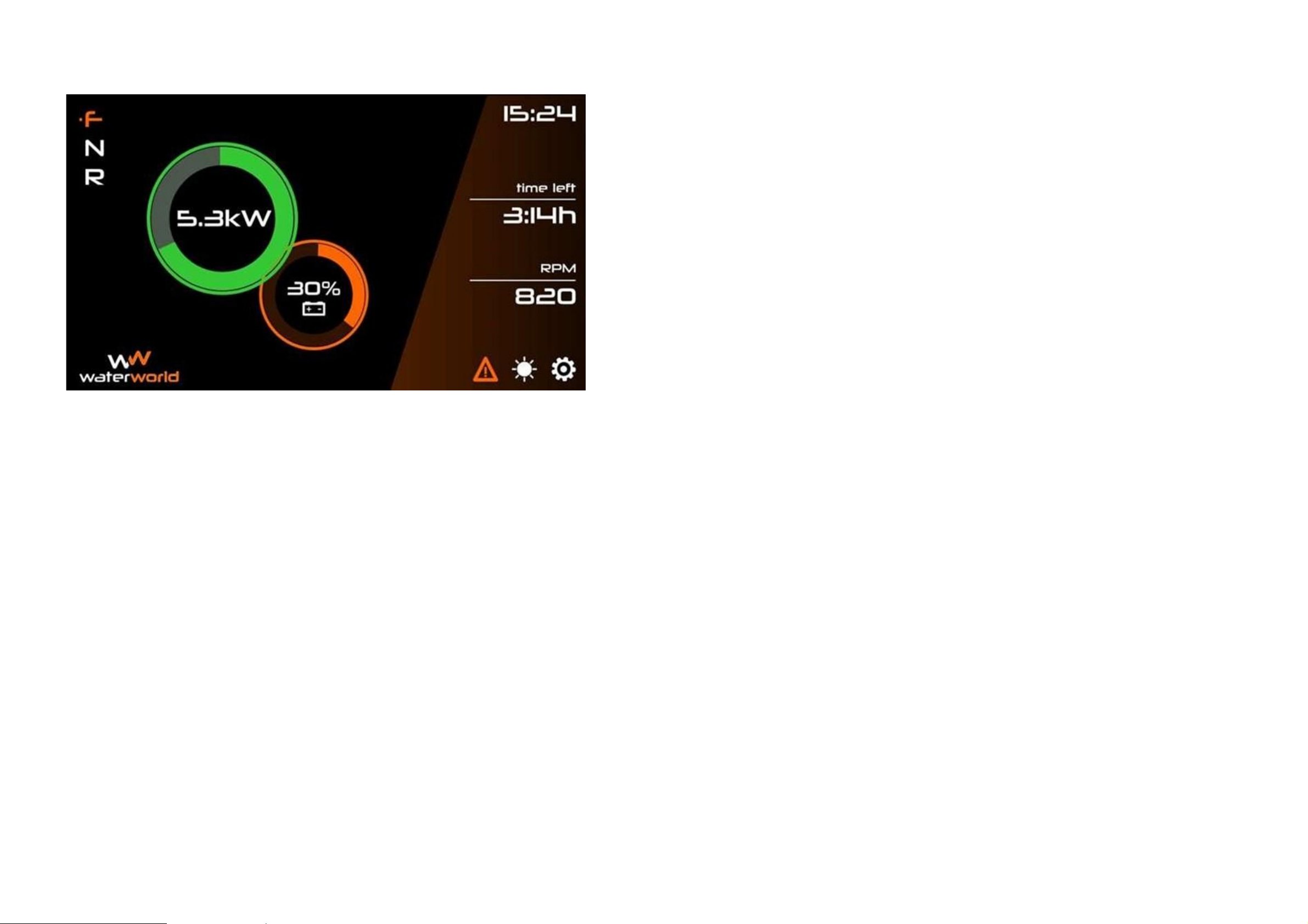
De characters F N R (Forward Neutral Reverse) in the upper left corner of the screen show whether your
throttle is in forward, neutral or reverse.
The green circle shows the engine power in kilowatts that is currently being used. The orange circle shows
you the indication of your remaining battery capacity in percent.
The "time left" shows the remaining sailing time in hours and minutes. It is only shown when the engine is
in F (forward) and using power. If the engine is in N (neutral), no value is shown here. The meter starts
from the last saved value. Also at restarting the counting starts from the last saved value unless you set it
to 100% because the batteries are charged (see instruction below).
RPM shows engine speed.
The
orange warning triangle
shows the presence of any
error codes
. If an error or malfunction occurs, a
pop-up will inform you of the meaning of the error. If it is an error that will allow you to continue sailing, you
can click on it to delete it. An orange warning triangle will appear at the bottom of the screen. There will also
be an acoustic signal, which you can also switch off when you have read the message. An overview of the codes
can be found in chapter 9.
By tapping the "sun" you can adjust the brightness of the screen.
If your charger has switched off after charging and shows the indication of a full battery, the motor
controller registers the higher voltage. At that moment a battery icon appears at the bottom of the screen.
When you click on this icon, you will be asked whether you really want to confirm that the battery is full.
If you click yes, the percentage will go up to 100%. This message does not work if the voltage is too low,
so that the battery is not reset to full by mistake. You only need to do this reset if the charger has gone
out after a charging session and finished charging. If you make a stop without charging, the display will
continue from where it left off when you turned off the engine.
When charging is still in progress, the battery icon may also appear, because at that moment a higher
voltage is also being registered temporarily. If you then click on "battery full", the low voltage message
will appear more quickly than usual during use, as well as the indication "drive slowly". The battery
indication will then no longer be correct until you have recharged the batteries to 100%.
Arriving and berthing
• When docking, ensure that the throttle is in the neutral position.
• Turn the system off using the ignition switch.
• Turn off the main power switch. NOTE: Also turn the system off at the main switch when swimming around
the boat or carrying out repairs and maintenance.
• Connect shore power and check whether the charger is working properly.
36 37
Page 20
Inspections during the boating season
Give your WaterWorld system and its energy system regular attention, even during the boating season.
We recommend paying attention to the following points
:
• Make sure that the space underneath the boat and under the engine is kept dry so that the engine
and controller are not flooded or excessive condensation can form. It is advisable to install an
automatic bilge pump at the deepest point of the boat and to check its correct operation at regular
intervals. Check this before every sailing trip. If there is water in the boat and the electronics have
become wet, dry them and contact your installer. Do not switch on the engine in this situation
.
• Keep engine and controller as well as the other parts of the system clean and dry. You can clean
it with a slightly damp cloth. Do not use water to clean the system.
• Always keep your system connected to shore power when you are not sailing. This prevents
empty batteries. The charger will stop automatically when the batteries are full. Always check
if the charger turns on when you switch it on.
Attention! Before carrying out inspections or maintenance, always switch off the system at the main power switch.
39
38
7. MAINTENANCE AND SERVICE
Inspections during the boating season
Annual inspections by you or your supplier
Winter storage
Operating the engine on salt water
Page 21

Annual inspections by you or your supplier
Preferably have your system inspected every year by your supplier or installer. He will check the system
on the following points:
• Proper functioning of all components.
• Possible moisture problems, corrosion of contacts, battery poles or plugs. Preventive application of
contact spray and lubrication of battery poles
.
• Greasing the shaft from the engine.
• All terminal clamps and connectors are securely in place.
• All fixing bolts and nuts must be properly tightened.
• Possible damage to cables and components.
• The condition and correct voltage of all batteries.
•
Load:
If you have a multimeter, check the voltage of each battery by putting the meter on the
+ and - terminals of one battery while the engine is running. There should be no difference
between the batteries greater than 0.1 Volt. If this is the case, please contact your supplier
or installer.
•
No-load:
After charging the batteries, measure them individually and check again that the
difference between them is not too great. Check the specifications of your battery, or ask
your supplier, if the voltage is high enough.
• Any imbalance in the engine/propeller shaft system.
• The correct settings of the display.
Winter storage
During and after winter storage, the same recommended checks apply as above. Pay special attention to
charging the batteries and keeping them charged. If your boat has a power point during winter storage,
leave the shore power connected. Your charger will automatically switch on and off when needed. It is
recommended that you check your boat and batteries at least twice during the winter to make sure the
charger is connected and the batteries are still charged.
If there is no power point near your boat, put the boat away with fully charged lead-acid batteries and disconnect
the main + and - of the battery pack. Make sure that no consumers are connected to the battery pack. With
lithium batteries, it is wise to store the boat in the same way, but with batteries that are around 50% charged.
This extends the service life of these batteries
.
Using the engine on salt water
When operating on salt water, it is important to pay extra attention to the following points.
• Close the installation area(s) tightly to salt water.
• Ensure that these areas are ventilated.
• Check all components regularly for corrosion.
• Clean thoroughly twice a year.
• Grease the shaft.
• Use protective spray for the rest of the engine if necessary..
40 41
Page 22
Engine specifications
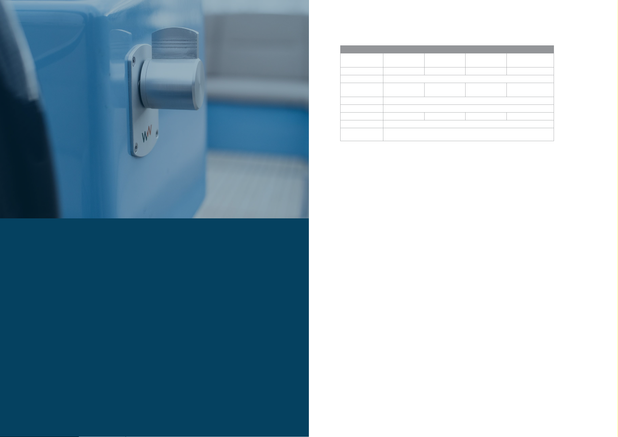
Model
WW 4.0
WW 7.5
WW 10.0
WW 15.0
Max. power
consumption (S1)
4.4 kW
8.25 kW
11 kW
16 kW
Nom. RPM
1450
1350
1450 1450
Voltage
48 V
Max. current
(Ampères)
92 172 230 400
Type
Asynchronous
Sensor
Sensorless
Weight (kg) 39 76 76
100
IP rating engine
IP 65
IP rating
controller
IP 65
ATTENTION!
Stroom kan bij accelereren tijdelijk hoger zijn.
Electric engine
Voltage: 3 X 34 Vac @ 50 Hz
Speed: 1350 / 1450 RPM (depending on engine type)
Max speed: 1500 RPM
Insulation class: H (180 °C)
Thermal protection: PTY84-130
°C
Max temperature: 135 °C
Outgoing shaft: 38MM / 28MM
Cooling: Air-cooled, shaft-mounted fan
Engine controller
Voltage: 48V
Max temperature: 80 °C
Cooling: Air, 2 fans
Electric motor control: sensorless
Control lever
Type: WaterWorld basic control.
Controller: Rotation and hall sensor determined forward / reverse. (WW-017)
Potentiometer + hall sensor for additional control and safe operation. (WW-016)
Relais
Voltage: 48V DC
Max continuous current: 200A / 400A (depending on engine type)
43
42
Display
Inspections
Dimensions
Propeller advice
Engine specifications
Electric motor
Motor controller
Throttle
Relay
8. TECHNICAL SPECIFICATIONS
Page 23

Display
Power supply via motor controller
In the appendices to this manual you will find the dimensional drawings of the various models of WaterWorld motors.
On www.ww-el.com you will find the drawings and also 3D files.
Propeller selection guidelines
Below is a guideline for the choice of propeller size. NB: the optimum propeller for an individual boat
may differ from this, every boat is different.
4.0 kW motor and a boat travelling slower than 11 km/h
- 12 x 7 3 - blade propeller
- 12 x 8 3 - blade propeller
4.0 kW motor and a boat travelling at over 11 km/h
- 12 x 8 4 - blade propeller
7.5 kW motor and a boat travelling slower than 10 km/h
- 14 x 9 3 - blade propeller
- 13 x 10 3 - blade propeller
7.5 kW motor and a boat travelling at over 10 km/h
- 14 x 9 4 - blade propeller
- 13 x 10 4 - blade propeller
- 15 x 8 4 - blade propeller
- 15 x 9 3 - blade propeller
10 kW motor and a boat travelling at less than 10 km/h
- 14 x 9 3 - blade propeller
10 kW motor and a boat travelling at more than 10 km/h
- 14 x 10 3 - blade propeller
- 15 x 9 3 - blade propeller
- 14 x 10 4 - blade propeller (only for lighter boats)
- 15 x 9 4 - blade propeller (only for lighter boats)
- 16 x 8 3 - blade propeller (only for lighter boats)
15 kW motor for lower speeds (approx. 11 km/h)
- 14 x 11 3 - blade propeller
- 16 x 9 3 - blade propeller
- 16 x 9 4 - blade propeller
- 15 x 10 4 - blade propeller
15 kW motor for higher speeds (approx. 15 km/h.)
- 15 x 11 3 - blade propeller
- 16 x 10 4 - blade propeller
44 45
Page 24
Error codes for malfunction
These codes appear in your display (see also chapter 6 under "explanation of the display").
In case of the following errors, check the data in the display regarding temperature, voltage, the smooth
running of the propeller shaft installation and the correct connection of all cabling. If the problem cannot
be solved, please contact your supplier.
Voltage too low
The controller measures a voltage below 46 Volts (minimum start-up ok voltage) or has measured a voltage below
this.
Voltage too high
The controller measures or has measured a higher voltage than the settings allow (70V = max voltage).
Throttle lever
The controller detects a problem in the signal from the throttle, usually a bad connection in the cabling.
Engine temp.
The temperature sensor in the engine block is above 130 • C.
Blocked engine
The measured engine rpm is less than 70% of the expected rpm and less than 500 revs.
Speed too low
The measured engine rpm is less than 85% of the expected rpm at maximum power.
Insufficient torque
The measured engine rpm is equal to the expected rpm, but the amperage is at less than 80% at maximum power.
On the left RJ-45 CAN connector the controller is able to display error codes (the two inputs on top of the
controller where you can put a network cable).
An orange LED always flashes for 1 second, even if there are no errors. If the controller gives an error, the
1-second blink is followed by one or more short blinks of 200ms, the number of short blinks indicates the
error.
47
46
9. FAULTS AND PROBLEMS
Faults and Problems
Problems
Page 25
Examine the following diagram to find out what is going on:
Problems
The following are some of the problems that may occur.
My engine quickly loses power
• It is possible that the engine control unit is reducing the power because your battery pack is low.
Check the remaining percentage on the display combined with the voltage while the motor is running.
If the voltage drops below 46 Volts, the motor will reduce power for that reason. As soon as the
voltage drops below 42 Volts, depending on the setting, the motor will stop completely.
• - The cooling is insufficient. When the engine heats up too much, it will also reduce its power
output and eventually stop. The most common causes of this are a badly running propeller shaft
and a propeller selected too heavily. See also the propeller selection table on page 35.
My engine vibrates and makes too much noise
There may be several causes for this, which you can rule out one by one:
• the engine is not properly aligned with the propeller shaft
• the engine is mounted too high on the engine foundation
• the flange is not straight, or not mounted straight on the engine
• the propeller shaft is not straight and needs to be aligned
• there is damage to the propeller underneath the boat.
My engine has less power
You may have something in the propeller or it may be out of balance.
If the propeller shaft can be turned very slightly by hand and this problem is present immediately after
installation, a heavier propeller can probably be chosen.
•
ATTENTION! Be sure to first turn of your system before you put your hands anywhere near the propeller shaft!
I have lost my key
Always have a spare key. Have one made if you have lost one.
If you do need a new key, contact your supplier.
48 49
Aantal
korte
pulsen
Error
Uitleg
0 Geen error
Only a long blink of 1 second can be seen, the system is working
properly.
1 Low Voltage
The controller measures a voltage below 46 Volts (minimum start-up
voltage) or has measured a voltage below that. In this case, you should
solve the voltage problem by charging the batteries or checking the
quality of the connections..
2 High Voltage
The controller measures or has measured a higher voltage than the
settings allow (70V = max voltage). In this case, there is no proper battery
pack connected and this needs to be fixed before the motor can be used..
3 No Throttle
The controller detects a problem in the signal from the throttle, usually a
bad connection in the wiring. Dismantle the wiring from the throttle to
the controller, inspect it and reconnect it.
4 High engine temp.
The temperature sensor in the engine block is above 130 degrees. Find out
what is causing it, e.g. no ventilation of the engine compartment, and fix the
problem.
5 Jammed engine
The measured engine rpm is less than 70% of the expected engine rpm
and lower than 500 rpm. This usually indicates a blocking of the propeller
shaft, for example by a rope in the propeller, or a defective bearing.
6 Low RPM
The measured engine rpm is less than 85% of the expected engine rpm at
maximum power. See section 5.
7 Insufficient torque
The measured engine rpm is equal to the expected engine rpm, but the
amperage is less than 80% at maximum power. The engine can deliver its
power too easily. You may have a propeller that is a few sizes too light, or the
propeller may be rotating on the shaft.
.
Page 26
Warranty periods
The warranty period is 24 months and covers all parts of the WaterWorld system. The warranty period begins on the day
the WaterWorld system is delivered to the end customer.
For WaterWorld systems that are used - even temporarily - in commercial operation, the warranty period is adjusted to
one year after delivery of the product to the customer.
In all cases, the warranty is voided six months after the discovery of the defect.
Warranty conditions
Water World Electronics BV guarantees the end customer of a WaterWorld system that the product will be free
from defects in material and workmanship during the warranty period. WaterWorld will assume the cost for the
end customer to correct any material or workmanship defects.
This acceptance of costs does not apply to any collateral damage caused by a warranty issue and does not apply
to any other financial damage (e.g. costs for towing, telecommunication, meals, lodging, loss of use, loss of
time, etc.).
Water World Electronics BV decides whether defective parts will be repaired or replaced. Distributors and
dealers, who perform repair work on WaterWorld motors, have no authority to make legally binding statements
for Water World Electronics.
Wearing parts and routine maintenance work are excluded from the warranty. Cables and fasteners are also
excluded from warranty
.
Your supplier or WaterWorld has the right to refuse warranty if,
• The warranty has not been properly filed (see under warranty procedure).
• The product has not been handled properly.
• The safety, operating and maintenance instructions in the manual were not observed.
• Prescribed maintenance has not been performed or documented.
• The product has been damaged by external influences, an accident or in some other way beyond
WaterWorld's control.
• The WaterWorld system has been modified in any way or equipped with parts or accessories not
expressly permitted or recommended by WaterWorld.
• Prior maintenance or repair work has not been carried out by companies authorised by WaterWorld,
or original spare parts have not been used unless t
he customer can prove that the facts giving rise
to the refusal to grant a warranty had no effect on the occurrence of the fault.
51
50
Warranty
Warranty periods
Warranty conditions
Warranty procedure
Page 27
Warranty procedure
The observance of the following warranty procedure is a prerequisite for making a warranty claim.
• Contact your WaterWorld supplier in case of complaint.
• Have your purchase invoice at hand, the supplier will need it to check where and when your WaterWorld system was
purchased
.
•
ATTENTION! Your purchase receipt or invoice is your guarantee certificate. So be sure to store it carefully
after purchase!
• Also keep the serial number of the engine at hand, if it is not already on the purchase invoice.
• Send or give a good description of the complaint, the circumstances under which it occurs and further any
relevant information that may help your supplier to assess the nature and seriousness of the complaint. If
necessary and possible, take photographs of the system and the overall situation that may help.
• The supplier may ask you to carry out a number of checks on the system first, in order to better assess the
complaint.
• Please note that incorrect transport of products to the WaterWorld supplier is not covered by warranty.
Decommissioning of the product/recycling
WaterWorld engines have been constructed in accordance with the EC directive 2002/96. This directive regulates the
recycling of electrical and electronic appliances in order to protect the environment. In accordance with the regional
regulations, you can dispose of the engine at a collection points. From there it will be professionally recycled.
52 53
Page 28
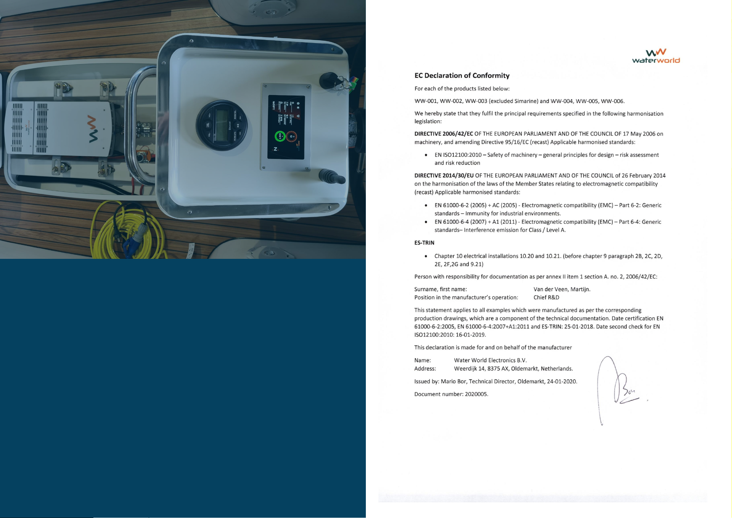
Declaration of conformity
55
54
ANNEXES
Declaration of conformity
Page 29
Questions? Feel free to contact us
.
Contact information
Water World Electronics Weerdijk 14
8375 AX Oldemarkt, the Netherlands
Telephone: +31 (0)561 451 636
Version Jan 2022
 Loading...