

Page 1

INSTALLATION MANUAL FOR DIGITAL PRESSURE CONTROL
Model WWDPC
Your WWDPC has been carefully assembled and factory tested. To enjoy
the full service this unit can provide, you should read and follow all of the
instructions in this manual. When all installation steps have been completed,
make sure you also follow the enclosed post-installation and startup checklists
before using your WATER WORKER® product. You should also read carefully
the sections describing proper product maintenance and follow the required
procedures as you use your WWDPC. Keep this manual with the product. This
manual may become out-of-date by later amendments. Check our web site,
www.waterworkerDIY.com or ask your WATER WORKER® supplier for any
updates relating to your product. This product comes with a limited two (2)
year warranty. Visit www.waterworkerdiy.com for complete warranty details.
THIS IS THE SAFETY ALERT SYMBOL. IT IS USED TO ALERT YOU
TO POTENTIAL PERSONAL INJURY AND OTHER HAZARDS. OBEY
ALL SAFETY MESSAGES THAT FOLLOW THIS SYMBOL TO REDUCE
THE RISK OF POSSIBLE INJURY AS WELL AS PROPERTY DAMAGE.
INSTALLER: LEAVE THIS MANUAL WITH THE OWNER
Part # 9046-0002 (01/19)
1
Patent Pending
Page 2
INSTALLATION INSTRUCTIONS
Unit is Recommended to be Installed by a Qualified Professional
PLUMBING CONNECTION (1/4" NPT FEMALE SYSTEM CONNECTION)
1. Select a location for the WWDPC. The WWDPC should be mounted near the
pressure tank or pump, depending upon the installation
LOCATE THE WWDPC FOLLOWING ALL LOCAL CODES. DO
NOT LOCATE THE UNIT WHERE IT CAN BE AFFECTED BY
FLOODING.
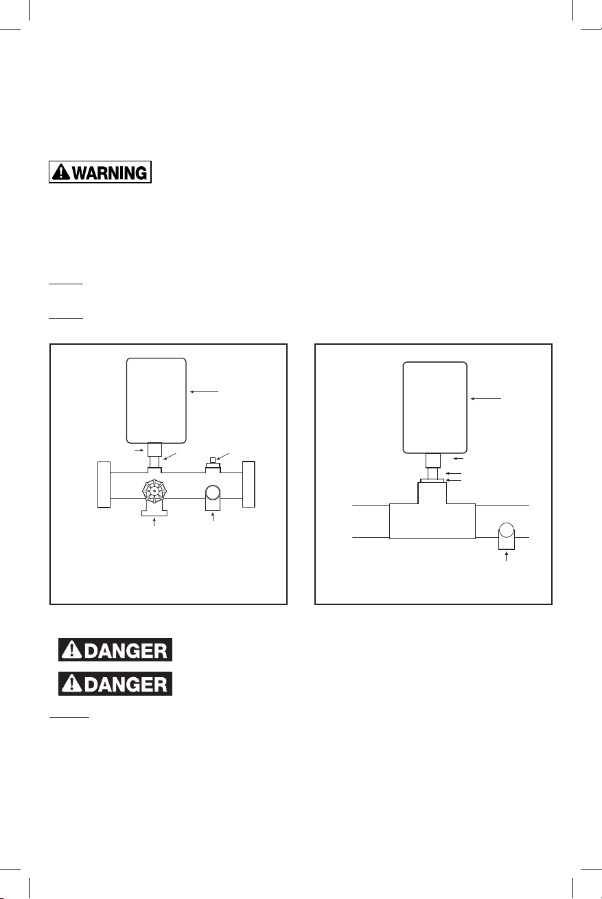
2. You may assemble the WWDPC to a “Tank Tee” or “Tank Cross” (Figure
1) or adapt the unit to an in-line pipe fitting (Figure 2). Use Teflon® sealing
tape or pipe sealant. Tighten the WWDPC using the wrench flats provided
on the bottom connection. DO NOT EXCEED 15LB./FT. of torque.
Note: Do not allow pipe sealant or other contaminants to enter the small port in
the WWDPC connection.
Note: A mechanical pressure gauge is not required. Use the appropriate plug to
block any unused ports.
1/4" NPT Female
System Connection
Drain
Valve
INSTALLATION ON TYPICAL TANK TEE
Fig. 1
WWDPC
Pipe Nipple Plug
Relief Valve
Tee
GENERAL IN-LINE INSTALLATION
Fig. 2
WWDPC
1/4" NPT Female
System Connection
Pipe Nipple
Adapt as necessary
Relief Valve
ELECTRICAL CONNECTION
ELECTROCUTION HAZARD. FIRST DISCONNECT ALL
ELECTRICAL POWER BEFORE SERVICING.
ELECTROCUTION HAZARD. THE WWDPC MUST BE
ELECTRICALLY GROUNDED.
NOTE: The WWDPC will operate on 115 VAC & 230 VAC systems. Its ambient air
temperature rating is 122°F / 50°C.
1. Disconnect power and verify with a volt meter.
2. Determine the pump electrical requirements. If unknown, contact the pump
manufacturer.
3.
Select the appropriate wire gauge per local codes and the pump manufacturer’s
recommendation.
2
Page 3
4. Loosen the screw on the cover of the controller and remove the plastic cover,
LINE IN
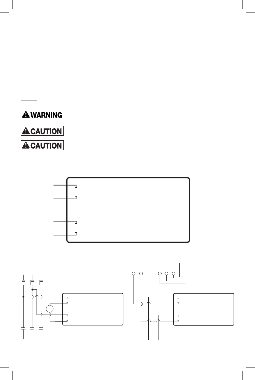
3-WIRE, SINGLE PHASE CONTROL BOX
TO MOTOR
TYPICAL 3-PHASE CONTROL BOX
exposing the wiring pigtails. (When reassembling cover, do not over-tighten
screw.)
5. The wire conduit hub is to be connected to the conduit before the hub is
connected to the enclosure. The maximum hub diameter cannot exceed 1.15".
Larger hub will interfere with cover closure.
6. The opening of the enclosure shall be closed with hubs rated 3, 3S, 3SX, 3X, 4, 4X,
6 or 6P.
NOTE: Steps 5 and 6 are required for outdoor installations only.
7. Following all electrical codes, wire the WWDPC using the wiring diagram below
(Figure 3).
NOTE: The WWDPC has openings to accept standard conduit terminations.
Outdoor installations must use watertight connections.
UNIT MUST NOT BE SUPPORTED SOLELY BY THE ELECTRICAL
CONDUIT.
WATERTIGHT CONDUIT CONNECTIONS MUST BE USED WHEN
EXPOSED TO DIRECT WEATHER, MOISTURE OR HIGH HUMIDITY.
ELECTRICAL BONDING BETWEEN CONDUIT CONNECTIONS IS
NOT AUTOMATIC AND MUST BE PROVIDED AS PART OF THE
INSTALLATION. BONDING KIT, PART #146-2350 CAN BE ORDERED SEPERATELY.
Fig. 3
®
Digital Pressure Control
LINE
Water Worker
Black
LINE
Blue
White
White
w/Black
FUSES
COIL
CONTACTS
Water Worker Digital Pressure Control
LOAD
LOAD
L1
L2 L3
Black
Blue
White
White
w/Black
L1
L2 YBR
3
TO
MOTOR
Water Worker Digital Pressure Control
Black
Blue
White
White
w/Black
Page 4
START UP
BEFORE CONTINUING, CHECK FOR OPEN DRAIN VALVES OR
OTHER SOURCES OF FLOODING BEFORE STARTING UNIT.
1. Prime pump if necessary and adjust tank precharge to manufacturer’s
recommendation for intended pressure range. The factory WWDPC setting
is 40 psi cut-in and 60 psi cut-out.
2. Turn on power and ensure WWDPC display illuminates, “88” will appear,
then code revision number, then “00”. Display will blank momentarily and
the pump will start. If not, check installation.
3. The display will now read the current line pressure.
4. Allow the pump to reach the factory cut-off setting of 60 psi. IF THE PUMP
CANNOT REACH THIS SETTING, DISCONNECT POWER AND SEE THE
TROUBLESHOOTING SECTION ON PAGE 5.
5. Check for leaks and repair as necessary before proceeding.
6. Proceed to the ADJUSTMENT section.
NOTE: During the first 30 seconds after start up, the pump can be made to
operate manually by depressing the 5 arrow for 6 seconds. This is useful for
priming jet pumps.
DEVICE ADJUSTMENT (Entering Programming Mode)
NOTE: Differential pressure cannot exceed 55 psi or be less than 10 psi. If display
will not change, alter cut-in or cut-out to within 55 psi.
1. Press and hold . When “LO” appears, release. This will determine the
pressure at which the pump activates.
2. When number appears, tap 5 or 6 to change cut-in setting.
3. Press again. When “HI” appears, tap 5 or 6 to change cut-out setting.
This will determine the pressure at which the pump shuts off.
NOTE: Depressing a third time will display the last Error Code in memory (see
Error Code table in Troubleshooting section). If no errors have occurred, the
display will show “- -”
4. After approx. 10 seconds “Pr” will appear, indicating the settings are
programmed. Display will then revert to line pressure.
NOTE: The settings will now be stored until changed manually, even in the event
of power failure.
NOTE: If pump cannot reach cut-out setting within 5 minutes with no water
running, lower the pressure settings to fall within the pump’s pressure capabilities.
NOTE: Pressing 5 6 together for 3 seconds will rotate the screen 180 degrees.
This is useful if the control is mounted in an inverted position.
OPERATION
The WWDPC incorporates an accurate pressure sensing system capable of
maintaining the set pressure range without the need for regular service or
adjustment. The WWDPC controls the on/off cycling of the pump within the
selected pressure range (see ADJUSTMENT section).
The WWDPC also incorporates built-in diagnostic functions to protect the system
and alert the user or installer to potential problems. If a fault is found, an error
code will be displayed, indicating that service may be necessary. Error codes are
listed in the TROUBLESHOOTING section.
4
Page 5
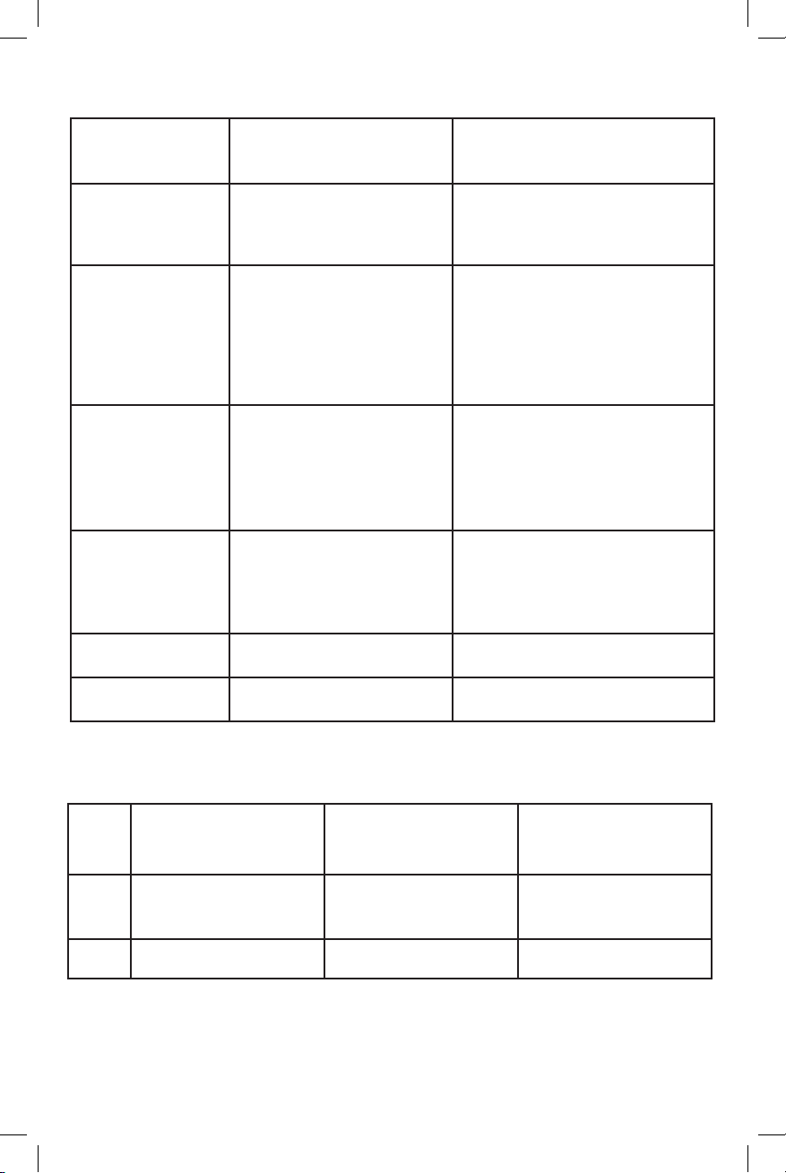
TROUBLESHOOTING
Problem Cause Solution
Display will not
illuminate
HI or LO setting will
not change
Pump will not reach
cut-off (HI)
Pump rapid cycles
Pump will not
activate
Water flow stops
before cut-in
Display reads
upside-down
No power
Improper wiring
Improper voltage
Differential attempted is
below 10 psi or above 55 psi
Minimum cut-in reached
Maximum cutout reached
HI setting greater than pump
rating
Insufficient prime (above
ground pumps)
No water to pump
Pump or line blockage
Fixture open or leak in
plumbing
Pressure tank too small
Differential too narrow
Waterlogged pressure tank
Improper tank air charge
Improper wiring
No power
WWDPC error encountered
Faulty pump
Improper wiring (WWDPC or
pump)
Tank precharge too high Adjust precharge per manufac-
Mounting position may vary
Check circuit breaker and wiring
connection
Check polarity and wiring
Ensure voltage is 115V or 230V
Differential cannot be less than 10
psi or greater than 55 psi
LO cannot be set below 10 psi
HI cannot be set above 80 psi
Reduce HI setting to within pump
capability
Prime pump as directed by
manufacturer - use manual
operation mode
Check shutoff valves
Remove obstructions
Determine cause of flow and
remedy
Size tank per manufacturer’s
literature
Spread range via HI or LO setting
Replace tank
Charge as instructed by
manufacturer
Check proper wiring to “line in”, L1
& L2
Check circuit breaker and wiring
connections
See error chart below
Contact pump manufacturer
Check wiring per manufacturer’s
instructions
turer’s instruction
Press 5 6 together for 3 seconds
and screen will rotate 180 degrees
MODEL WWDPC ERROR CODES
Error
Code Reason Action Solution
Rapid cycle
E1
Excessive amp draw
E2 Low-suction shutoff
(running pressure) below
10 PSI
E3 Improper voltage Shutoff after 2 min.* Restore voltage to
To reset switch at any time: Press 5 6 buttons simultaneously for 5 seconds.
*Unit will monitor voltage until voltage condition returns to normal. Pump will restart automatically.
UNIT CONTAINS NO SERVICEABLE PARTS. REMOVAL OF MAIN CIRCUIT BOARD COVER WILL
VOID WARRANTY.
Switch continues to
operate
Shutoff. Auto restart
after 60 min.
5
See “Pump Rapid Cycle”
above
Have pump checked for
proper operation
(A) Determine cause of
low-suction
(B) Check Wiring
(C) Inspect pump
proper range
Page 6
GENERAL SAFETY INFORMATION
WARNING: REVIEW ALL GENERAL SAFETY INFORMATION PRIOR TO INSTALLATION.
READ CAREFULLY THE PRODUCT INSTALLATION,
OPERATING AND MAINTENANCE INSTRUCTIONS. FAILURE
TO FOLLOW THE INSTRUCTIONS AND WARNINGS IN THE MANUAL MAY RESULT
IN SERIOUS OR FATAL INJURY AND/OR PROPERTY DAMAGE, AND WILL VOID
THE PRODUCT WARRANTY. THIS PRODUCT MUST BE INSTALLED BY A
QUALIFIED PROFESSIONAL. FOLLOW ALL APPLICABLE LOCAL AND STATE
CODES AND REGULATIONS, IN THE ABSENCE OF SUCH CODES, FOLLOW THE
CURRENT EDITIONS OF THE NATIONAL PLUMBING CODE AND NATIONAL
ELECTRIC CODE, AS APPLICABLE.
This product is used in conjunction with a system containing a
tank under pressure, which may over time corrode, weaken and
burst or explode, causing serious or fatal personal injury, leaking or flooding and/
or property damage. To minimize risk, a licensed professional must install and
periodically inspect and service the product and system. A drip pan connected
to an adequate drain must be installed if leaking or flooding could cause property
damage. Do not locate system in an area where leaking could cause property
damage.
EXPLOSION OR RUPTURE HAZARD. A relief valve must be
installed to prevent system pressure in excess of local code
requirement or maximum working pressure designated in the Product Manual,
whichever is less. Do not expose system to freezing temperatures or temperatures
in excess of 120 degrees. Failure to properly size the system or follow instructions
in the Manual may result in excessive strain on the system and may lead to
product failure, leakage, flooding and/or property damage.
This control is capable of running pumps to pressures that may
exceed the limitations of system components. Never set the
operating pressure higher than that of the safe system capacity.
This control can be adjusted to a narrow pressure differential.
This can cause the pump to cycle rapidly with an improperly
sized tank, leading to pump damage. This may require a larger pressure tank
than is normally used.
ELECTROCUTION HAZARD. Must be installed by qualified
professional. First disconnect all electrical power before
attempting service. For your safety, the information in this Manual must be
followed to minimize the risk of electric shock, property damage or
personal injury.
A water test must be taken before installation of any water
treatment equipment. The water quality can significantly
influence the life of your system. You should test for corrosive elements, acidity,
total solids and other relevant contaminants, including chlorine and treat your
water appropriately to insure satisfactory performance and prevent
premature failure.
Use only lead-free solder and flux for all sweat-solder
connections, as required by state and federal codes.
6
Page 7
DANGER! EXPLOSION HAZARD. When the well tank has been
in service and a change to a higher pre-charge pressure is
necessary due to a required change in the pressure switch setting, failure to
follow instructions below can cause a rupture or explosion, possibly causing
serious or fatal personal injury and/or property damage.
• Do not adjust or add pressure if there has been a loss of air.
• Do not adjust the pre-charge pressure if there is visible exterior corrosion.
• Do not adjust the pre-charge pressure if there has been a reduction of the
pump cycle time or the pre-charge pressure compared to its initial setting.
This is because reduction in pump cycle time can result from loss of tank air
pressure which in turn can mean there may be internal corrosion and any
re-pressurization or additional pressure could result in rupture or explosion.
• Do not install with components that are incompatible with the WWDPC.
This product can expose you to chemicals including lead,
which is known to the State of California to cause cancer and
birth defects or other reproductive harm. For more information go to
www.P65Warnings.ca.gov.
NOTE: Inspect for shipping damage and notify freight carrier or store where
purchased immediately if damage is present. To avoid risk of personal injury and
property damage, if the product appears to be malfunctioning or shows signs of
corrosion, call a qualified professional. Please read the entire owner’s manual and
installation instructions before installing our new Water Worker® product. Save
all documents and manuals for future reference. Use proper safety equipment
when installing. You must comply with all plumbing and electrical codes.
7
Page 8

T: 401.884.6300 • F: 401.885.2567 • www.waterworkerdiy.com
WATER WORKER is a registered trademark in the U.S. and elsewhere. All rights reserved.
 Loading...