

Water Worker HT6HB, HT14HB, HT20HB Installation Manual
INSTALLATION MANUAL FOR HORIZONTAL WELL SYSTEM TANKS
Models HT6HB, HT14HB and HT20HB
Keep this manual with the tank for future reference.
What You’ll Need
Recommended Tools
Adjustable Wrench
Adjustable Pliers
Pipe Wrench
Hacksaw
Screwdriver
Tape Measure
Tire Pressure Gauge
Before You Start
Always be sure to equip your well system with a proper Pressure
Relief Valve. This should be capable of discharging the full output of
the pump at or below the maximum working pressure of the lowest
rated component in the system. See the owner’s manual for your
pump for output information. This is vital for safe operation of the
well system. THIS PRODUCT COMES WITH A 5 YEAR WARRANTY.
SEE WATER WORKER LIMITED WARRANTY FOR DETAILS.
READ CAREFULLY THE PRODUCT INSTALLATION,
FAILURE TO FOLLOW THE INSTRUCTIONS AND WARNINGS IN
THE MANUAL MAY RESULT IN SERIOUS OR FATAL INJURY AND/OR
PROPERTY DAMAGE, AND WILL VOID THE PRODUCT WARRANTY.
THIS PRODUCT MUST BE INSTALLED BY A QUALIFIED PROFESSIONAL.
FOLLOW ALL APPLICABLE LOCAL AND STATE CODES AND
REGULATIONS, IN THE ABSENCE OF SUCH CODES, FOLLOW THE
CURRENT EDITIONS OF THE NATIONAL PLUMBING CODE AND
NATIONAL ELECTRIC CODE, AS APPLICABLE.
THIS IS THE SAFETY ALERT SYMBOL. IT IS USED TO
ALERT YOU TO POTENTIAL PERSONAL INJURY AND
OTHER HAZARDS. OBEY ALL SAFETY MESSAGES THAT
FOLLOW THIS SYMBOL TO REDUCE THE RISK OF PERSONAL
INJURY AS WELL AS PROPERTY DAMAGE.
IMPORTANT GENERAL SAFETY INFORMATION - ADDITIONAL SPECIFIC
SAFETY ALERTS APPEAR IN THE FOLLOWING INSTRUCTIONS.
lead to product failure, leaking or flooding or property damage.
pressures (75 psig or more). This will protect the well tank and
other system components should the pressure switch malfunction
and fail to shut the pump off. The relief valve should be installed
at the connection of the well tank to the system piping and have
a discharge equal to the pump’s capacity at 75 psig. At least once
every 3 years or if discharge is present, a licensed contractor should
inspect the temperature and pressure relief valve and replace if
corrosion is evident or the valve does not function. FAILURE TO
INSPECT THIS VALVE AS DIRECTED COULD RESULT IN UNSAFE
TEMPERATURE OR PRESSURE BUILD-UP WHICH CAN RESULT IN
PRODUCT FAILURE, SERIOUS INJURY OR DEATH AND/OR SEVERE
PROPERTY DAMAGE AND VOID THE PRODUCT WARRANTY.
Part #: 9015-377 (07/12)
OPERATING AND MAINTENANCE MANUAL.
Failure to utilize a properly sized well tank will result
in excessive strain on the pump and may ultimately
RELIEF VALVE REQUIRED. A relief valve should
be installed which is set to open at excessive
Additional Parts Required (Not Included)
Tank Water Connection Size:
HT6HB 3/4" NPTM
HT14HB and HT20HB 1" NPTM
Pressure Gauge
Relief Valve
Check Valve
Drain Valve
Pressure Switch
Teflon® Tape
How To Install The Tank
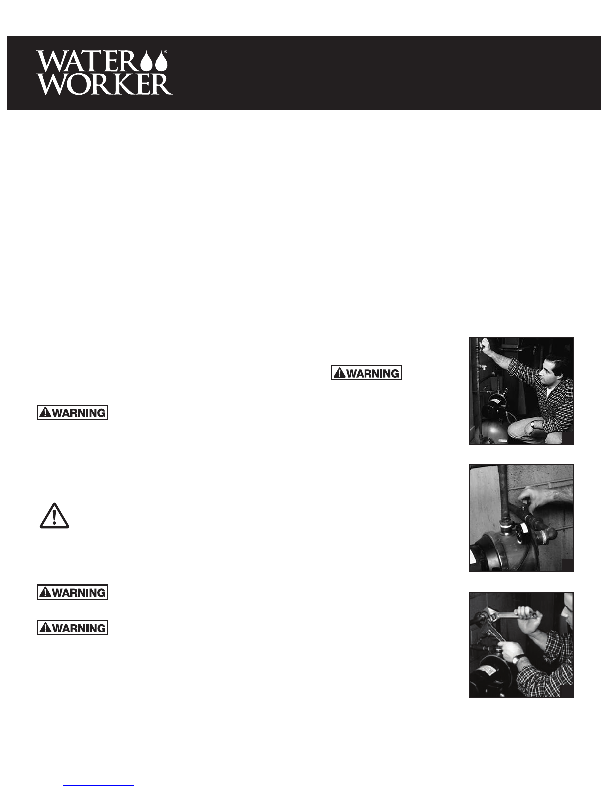
1. Find the fuse or circuit breaker
panel for your house. Turn off the
power to the well pump.
in this manual must be followed
to minimize the risk of electric
shock, property damage or
personal injury. Properly ground
to conform with all governing
codes and ordinances.
2. Open a faucet inside the house
as close to the tank as possible.
Drain the system as much as
possible by letting the water run
until it runs out.
3. Close the ball or gate valve (this
is the valve that controls the
flow of water from the tank into
the plumbing system inside the
house) (Fig. 1)
4. Close the ball or gate valve on
the pump feed line, the pipe
through which the pump draws
water from the well into the
house. (Fig. 2) This stops water
from running back into the well.
5. Drain the pump system.
Place a bucket under the drain
nearest the existing tank. Or, run
a hose from the drain into a
bucket or floor drain. Loosen a
union coupling over the pump
using the pipe wrench and the
adjustable wrench. This will let
air into the system and let the
water run out. Loosen until the
water flows out. Let the water
run out of the system.
If there is no drain near the
tank, open the pipe union closest to the tank using the 12”
adjustable wrench or the 12” pipe wrench. If there are no
union couplings, use a pipe cutter to open the pipe. Insert a
coupling to re-close the system when you are done draining
the system. (Fig. 3)
-1-
For your safety
the information
,
1
2
3
6. If there are union couplings in
the piping, loosen all three union
couplings close to the tank using
the pipe wrench and adjustable
wrench. Undo completely when
they are loose enough to work by
hand. The pipes will come apart
when the couplings disconnect.
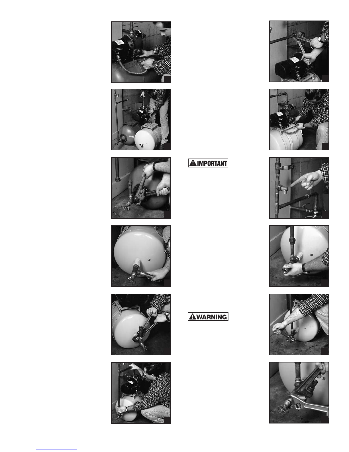
7. Loosen and remove all the bolts
that anchor the pump to the
pump stand using the adjustable
wrench. Remove the pump from
the pump stand of the existing
tank. (Fig. 4) If there is not enough
slack in the wiring to let the pump
rest on the floor, either rest it
on a stool or the new pump, or
disconnect the wiring. Don’t let it
hang in the air.
8. Remove the plastic cap on the air
valve on top of the tank. Check
the air charge in the new tank
using the tire pressure gauge.
Adjust the pre-charge pressure
in the tank to be 1-2 psi below
the pressure switch pump cut-in
setting. First look inside the cap to
the pressure switch to determine
the pump cut-in setting. It should
say “20/40” or “30/50” or the
like. The pressure in the tank
should be adjusted to be 2 psi
below the lower pressure of
these two numbers. That is, the
tank pressure should be set at
about 18 psi if the cap indicates a
setting of 20/40, or set at about
28 if the cap indicates a setting
of 30/50.
If this charge is too high, release
some air by pressing down on
the pin inside the air valve. If the
charge is too low, pump it up
using a bicycle tire pump or air
compressor.
Alternatively, you can adjust
the pressure switch to match
the pressure in the tank. See
instructions on the inside of the
pressure switch cap for how to
do this.
9. Place the pump on the pump
stand of the new tank. (Fig. 5)
Do not insert the bolts yet. (You
will need to move the pump
around to pipe it to the existing
pipes.)
10. Install the new tank.
a. Remove the inlet pipe to the
existing tank. (Fig. 6) Either
re-use the existing inlet assembly,
or purchase a tank installation kit,
which should include: a 3/4” x 4”
or so pipe nipple; a 3/4” fpt x 3/4”
fpt x 3/4” fpt pipe tee; and a 3/4”
fpt standard drain/boiler drain
valve.
b. Apply Teflon® tape to the
threaded male end of this inlet
pipe which inserts into the tank.
c. Insert this inlet pipe into the
female pipe threaded opening at
the end of the new tank. Tighten
hand tight. Then wrench tight
using the pipe wrench and the
12” adjustable wrench. (Fig. 7-8)
Make sure that the pipe to the
supply line ends up in a vertical
position pointing up. Tighten
slowly to make sure you do not
over tighten. (Fig. 8) Do not
loosen the pipe once tightened. If
you do, it is more likely to leak.
d. Move the existing tank out of the
way. Discard.
e. Move the new tank into position
with the inlet assembly attached.
f. If the two tanks are the same size,
then the piping will match up.
If the two tanks are different sizes,
then the piping for the new tank
probably will not match the old. In
this case, adjust the piping to fit.
If pipes are mismatched by only
a small amount, you can force the
pipes to fit or use nipples that are
longer or shorter to make ends
meet.
g. Match up the union couplings.
4
5
6
7
8
9
Tighten hand tight. (Fig. 9)
Tighten until wrench tight to seal,
using the 12” adjustable wrench
and the pipe wrench. (Fig. 10)
h. Insert the bolts for the pump into
place to hold it to the stand. Move
the tank as necessary underneath
the pump to make the holes in
the pump line up with the holes
in the pump stand. Screw on the
nuts to the bolts. Tighten wrench
tight using the adjustable wrench.
(Fig. 11)
11. Examine the plumbing system to
see if you have a pressure relief
valve between the pump and the
tank.
Always be sure
well system with a proper Pressure
Relief Valve.
The system shows what the
Pressure Relief Valve should look
like. (Fig. 12)
If you do have a Pressure Relief
Valve in the system, go on to
Step 12.
If you do not:
a. Remove the boiler drain from the
inlet valve now on the tank. Make
the pipe tee/nipple assembly.
Wrap Teflon® tape around one
of the male threaded ends of
the nipple. Insert it in one of the
female threaded openings in the
3/4” fpt x 3/4” fpt x 3/4” fpt
pipe tee. Tighten hand tight, then
wrench tight.
b. Install the pipe tee / nipple
assembly. (Fig. 13) Apply Teflon®
tape to the male thread at the
other end of the nipple (which is
now half inside the pipe tee). Insert
the pipe tee / nipple assembly
in the female threaded opening
on the tank inlet assembly from
which you removed the boiler
drain. Tighten hand tight, then
wrench tight.
an adequate drain must be
installed if leaking and flooding
could cause property damage to
the area adjacent to the appliance
or to lower floors of the structure.
c. Install the pressure relief valve.
Apply Teflon® tape to the male
threaded end of the valve.
Insert the pressure relief valve in
the female threaded opening on
the side of the pipe tee. Tighten
hand tight, then wrench tight.
(Fig. 14)
d. Insert the standard drain in the
female threaded opening of the end
of the pipe pee/nipple/pressure
relief valve assembly. Tighten hand
tight, then wrench tight. (Fig. 15)
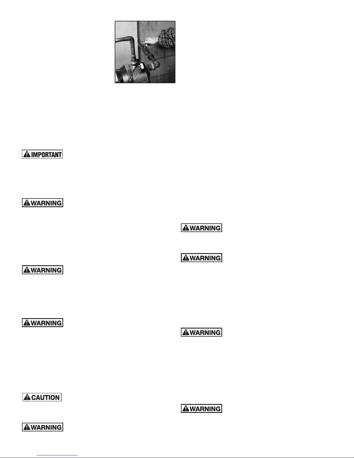
12. Open the ball or gate valve on the
pump feed line. (Fig. 16) Open the
ball or gate valve on the supply
line.
to equip your
A drip pan
connected to
10
11
12
13
14
15
-2-
13. Watch for any leaks in the system.
Turn the power back on. The
pump will start and fill the tank.
Turn on a faucet as far above the
pump as possible. This will let air
leave the system as it fills with
water. As soon as water comes
out of the faucet you just turned
on, turn it off. The pump will
now build pressure in the system
until that pressure reaches the
pump cut-out setting. If you
see a leak, turn off the power
immediately and tighten or re-do
16
the connection that is leaking. It should take 30 seconds to 1
minute for the pump to prime.
If the pump does not fill the tank, turn the system off and
check the manufacturer’s instructions for priming the pump.
Turn on a faucet nearby to see that the system is operating
properly.
IMPORTANT
Safety Instructions • Be sure to read.
This tank is designed for use with potable
water, limited to a maximum pressure of 100
psi and a maximum working temperature of 130°F. Please note: a
hot water heater or a boiler in a hydronic heating system will heat
water hotter than 130°F routinely. Use a thermal expansion tank
for hot water overflow from a hot water heater, or use an
expansion tank for hot water overflow in a hydronic heating
system. See the owner’s manual for your pump for output
information.
EXPLOSION OR RUPTURE HAZARD A relief
valve must be installed to prevent pressure in
excess of local code requirement or maximum working pressure
designated in the Product Manual, whichever is less. Do not
expose Product to freezing temperatures or temperatures in
excess of 200° F. Do not adjust the pre-charge or re-pressure this
Product except for any adjustments required at the time of initial
installation, especially if Product corroded, damaged or with
diminished integrity. Adjustments to pre-charge must be done at
ambient temperature only. Failure to properly size the Product or
follow these instructions may result in excessive strain on the
system lead to Product failure, serious or fatal personal injury,
leakage and/or property damage.
This Product, like most Products under
pressure, may over time corrode. Weaken and
burst or explode, causing serious or fatal injury, leaking or
flooding and/or property damage. To minimize risk, a licensed
professional must install and periodically inspect and service the
Product. A drip pan connected to an adequate drain must be
installed if leaking or flooding could cause property damage. Do
not locate in an area where leakage of the tank or connections
could cause property damage to the area adjacent to the
appliance or to lower floors of the structure.
Chlorine & Aggressive Water: The water
quality can significantly influence the life of
this Product. You should test for corrosive elements, acidity, total
solids and other relevant contaminants, including chlorine and
treat your water appropriately to insure satisfactory performance
and prevent premature failure.
DUE TO A REQUIRED CHANGE IN THE PRESSURE SWITCH
SETTING, FAILURE TO FOLLOW INSTRUCTION MANUAL CAN
CAUSE A RUPTURE OR EXPLOSION, POSSIBLY CAUSING
SERIOUS OR FATAL INJURY, AND/OR PROPERTY DAMAGE.
DO NOT ADJUST THE PRE-CHARGE PRESSURE IF THERE HAS
BEEN A REDUCTION OF THE PUMP CYCLE TIME OR THE PRECHARGE PRESSURE COMPARED TO ITS INITIAL SETTING.
THIS IS BECAUSE REDUCTION IN PUMP CYCLE TIME CAN
RESULT FROM LOSS OF TANK AIR PRESSURE WHICH IN TURN
CAN MEAN THERE MAY BE INTERNAL CORROSION AND ANY
RE-PRESSURIZATION OR ADDITIONAL PRESSURE COULD
RESULT IN RUPTURE OR EXPLOSION, AND/OR PROPERTY
DAMAGE.
MAXIMUM WORKING PRESSURES. Every well
working pressure for the well tank line. Should pressures exceed
125 psig, proper selection and sizing of an ASME constructed well
tank should be made.
excessive pressures (75 psig or more). This will protect the well
tank and other system components should the pressure switch
malfunction and fail to shut the pump off. The relief valve should
be installed at the connection of the well tank to the system piping
and have a discharge equal to the pump’s capacity at 75 psig.
At least once every 3 years or if discharge is present, a licensed
contractor should inspect the temperature and pressure relief
valve and replace if corrosion is evident or the valve does not
function. FAILURE TO INSPECT THIS VALVE AS DIRECTED COULD
RESULT IN UNSAFE TEMPERATURE OR PRESSURE BUILD-UP
WHICH CAN RESULT IN PRODUCT FAILURE, SERIOUS INJURY OR
DEATH AND/OR SEVERE PROPERTY DAMAGE AND VOID THE
PRODUCT WARRANTY.
electric shock, property damage or personal injury. Properly
ground to conform with all governing codes and ordinances
tank is air tested to 125 psig, the maximum
RELIEF VALVE REQUIRED. A relief valve
should be installed which is set to open at
For your safety, the information in this manual
must be followed to minimize the rise of
Note: Inspect for shipping damage and notify freight carrier or
store where purchased immediately if damage is present. To
avoid risk of personal injury and property damage, if the product
appears to be malfunctioning or shows signs of corrosion, call a
qualified professional immediately. Current copies of the Product
manual can be viewed at www.waterworkerdiy.com. Use proper
safety equipment when installing.
As in all plumbing products and water storage
especially during times of non-use. Consult your local plumbing
professional regarding any steps you may wish to take to safely
disinfect your home’s plumbing system.
CHANGE TO A HIGHER PRE-CHARGE PRESSURE IS NECESSARY
vessels, bacteria can grow in this Product,
DANGER! EXPLOSION HAZARD, WHEN THE
WELL TANK HAS BEEN IN SERVICE AND A
Do not use this tank for chemicals, solvents, petroleum products,
acids, or any fluids other than potable water. This can cause
premature failure due to corrosion.
Make sure that the pressure switch in your well system is set low
enough to shut off the pump. If all of the faucets and valves are
closed in your plumbing system and the pressure switch setting
is too high, the pump can run continuously without moving water
through the system. This could damage or burn out the pump.
CALIFORNIA PROPOSITION 65 WARNING!
State of California to cause cancer and to cause birth defects or
other reproductive harm. (California Installer/Contractor - California
law requires that this notice be given to consumer/end user of this
product.) For more information: www.waterworkerdiy.com/
prop65.htm
-3-
This product contains a chemical known by the

WATER WORKER® LIMITED PRODUCT WARRANTY
Products covered: all Products manufactured by WATER WORKER. (“WATER WORKER”) .
This warranty cannot be transferred – it is extended only to the original Purchaser or First User of the Product. By accepting and
keeping this Product you agree to all of the warranty terms and limitations of liability described below.
IMPORTANT WARNING – READ CAREFULLY THE INSTALLATION, OPERATING AND MAINTENANCE INSTRUCTIONS MANUAL
(“MANUAL”) to avoid serious personal injury and/or property damage and to ensure safe use and proper care of this product
Mail Your Product Registration Card Within 30 Days of Purchase to Ensure Your Warranty Coverage or Proof of Purchase Will Be
Required for All Warranty Claims.
Who Receives WATER WORKER’s Product Warranty
All purchasers or first users of the new Product. The Warranty is non-transferable.
What is covered by this Warranty
WATER WORKER warrants to the purchaser or first user of the new Product that at the time of manufacture, the Product is free from
defects in material and workmanship. Any warranty claim must be made within one (1) year unless another time period is set forth
in the Manual, measured from the time the Product was purchased.
What WATER WORKER Will Do If You Have a Covered Warranty Claim
In the event of a breach of the foregoing warranty, WATER WORKER will at its option either make repairs to correct any defect in
material or workmanship or supply and ship either new or used replacement parts or products. WATER WORKER will not accept
any claims for labor or other costs.
What This Warranty Does Not Cover - Exclusions and Limitations
This Warranty does not cover any failure or problem unless it was caused by a defect in material or workmanship. In addition, this
Warranty shall not apply:
• if the Product is not correctly installed, operated, repaired or maintained as described in the Manual provided with the Product;
• to any failure or malfunction resulting from abuse (including freezing); improper or negligent: handling, shipping (by anyone other
than WATER WORKER), storage, use, operation, accident; or alteration, lightning, flood or any other environmental condition;
• to any failure or problem resulting from the use of the Product for any purpose other than those specified in the accompanying
Manual or alteration of any part of the product;
• this Warranty does not cover labor costs, shipping charges, service charges, delivery expenses, administrative fees or any costs
incurred in removing or reinstalling the Product;
• this Warranty does not cover any claims submitted to WATER WORKER or a WATER WORKER-authorized distributor or retailer
more than 30 days after expiration of the applicable warranty time period described in this Warranty;
• this Warranty also does not cover repair or replacement costs not authorized in advance by WATER WORKER.
Additional Warranty Limitations
ALL IMPLIED WARRANTIES, INCLUDING THE IMPLIED WARRANTIES OF MERCHANTABILITY AND FITNESS FOR A PARTICULAR
PURPOSE ARE SPECIFICALLY DISCLAIMED.
Limitations of Remedies
THE REMEDIES CONTAINED IN THIS WARRANTY ARE THE PURCHASER’S OR FIRST USER’S EXCLUSIVE REMEDIES. IN NO
CIRCUMSTANCES WILL WATER WORKER BE LIABLE FOR MORE THAN, AND PURCHASER-FIRST USER’S REMEDIES SHALL NOT
EXCEED, THE PRICE PAID FOR THE PRODUCT. IN NO CASE SHALL WATER WORKER BE LIABLE FOR ANY SPECIAL, INDIRECT,
INCIDENTAL OR CONSEQUENTIAL DAMAGES, WHETHER RESULTING FROM NON-DELIVERY OR FROM THE USE, MISUSE, OR
INABILITY TO USE THE PRODUCT OR FROM DEFECTS IN THE PRODUCT OR FROM WATER WORKER’S OWN NEGLIGENCE OR
OTHER TORT. This exclusion applies regardless of whether such damages are sought for breach of warranty, breach of contract,
negligence, strict liability, in tort or under any other legal theory. Such damages include, but are not limited to, inconvenience, loss or
damage to property, mold, loss of profits, loss of savings or revenue, loss of use of the Products or any associated equipment, facilities,
buildings or services, downtime, and the claims of third parties including customers.
What To Do If You Have a Problem Covered By This Warranty
Any covered Warranty service must be authorized by WATER WORKER. Contact the person from whom you purchased the
Product, who must receive authorization from a WATER WORKER distributor or WATER WORKER. If you do not receive a
prompt response, call WATER WORKER directly at 877-324-8863. Notice of a Warranty claim should be submitted by the
authorized distributor for WATER WORKER at the following address:
WATER WORKER, Warranty Claim Dept.
1400 Division Road, West Warwick, RI 02893
Before WATER WORKER determines to provide any replacement part or Product, it may as a pre-condition to making such a
determination require that the warranty claimant ship the Product, postage prepaid to an authorized WATER WORKER distributor, or
to WATER WORKER and provide proof of purchase evidenced by the original sales receipt or Product registration.
Replacement Product Warranty
In case of replacement of a Product or any component part, WATER WORKER reserves the right to make changes in the design,
construction, or material of the substitute components or products, which shall be subject to all of the terms and limitations of this
Warranty, except that the applicable warranty periods shall be reduced by the amount of time the warranty claimant owned the
product prior to submitting notification of the warranty claim.
1400 Division Road, West Warwick, RI 02893 • T: 401.884.6300 • F: 401.885.2567 • www.waterworkerdiy.com
-4-
Part #: 9015-377 (07/12)
 Loading...