

WaterTech PRESSCONTROL WALL PRO T9, PRESSCONTROL WALL PRO T12, PRESSCONTROL WALL PRO T19, PRESSCONTROL WALL PRO T23, PRESSCONTROL WALL PRO T16 User Manual
Page 1
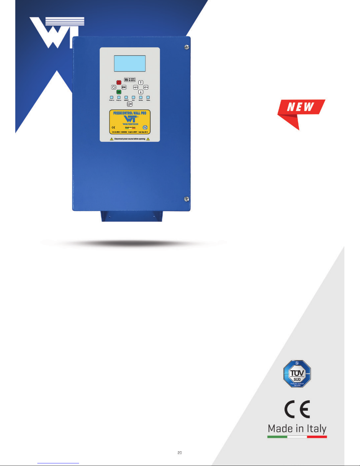
PRESSCONTROL
WALL PRO
VARIABLE FREQUENCY DRIVE FOR CONTROL AND PROTECTION
OF THE PUMP
PRESSCONTROL WALL PRO CAN OPERATE 400V THREE-PHASE PUMPS UP TO 15 HP.
Wall-mounted near the pump.
Varies the number of motor revolutions of the pump depending to the water withdrawal from the
system in order to maintain constant pressure and flow rate.
Allows to regulate the system pressure and the restart pump pressure.
Stops the pump in case of water shortage and protects it from dry running.
Is equipped with automatic restart in case of failure and anti-jamming function.
Can be installed on surface and submersible pumps.
Ensures energy saving.
Can be installed on surface pumps and submersible pumps.
Supplied with a 16 bar pressure sensor.
Standardly equipped with a communication interface to make pressure sets.
Standardly equipped with BMS protocol connection interface (Building Management System).
Standardly equipped with NFC technology for data transfer to the mobile phone.
Page 2
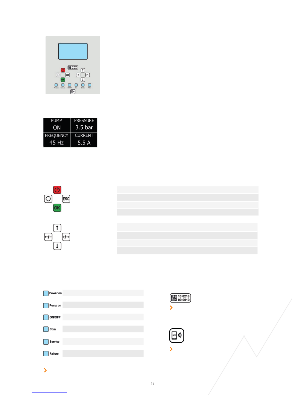
CONTROL AND SETTING PANEL
Setting up and starting Presscontrol Wall Pro is an extremely easy and intuitive
operation thanks to the large and bright display that shows the information and the
keyboard that allows you to enter and modify the pump operating parameters rapidly.
DISPLAY
KEYBOARD
SIGNALING
Serial number and data matrix of the device
The indicator LEDs of the main phases of operation of the device remain visible even when the display goes out to allow
the user to have the status of the system under control at all times.
Note: The Service Light does not preclude the system from operating. On the display, a description of the required action
will be displayed (e.g. recharging the pressure tank).
Data transmission with NFC technology.
Place mobile phone close to the icon for information transfer.
Device energized
Pump running
VFD On/Off
Communication between devices is active
Request for maintenance
Failure
The figure shows an example of displaying information divided into 4 quadrants:
1 - Pump status
3 - VFD operating frequency
2 - Real system pressure
4 - Current absorbed in Amperes
To save energy, the display will turn off one minute after the last action. To turn the
display on again, simply press any button on the keyboard.
ON/OFF BUTTON
Starts and stops the pump
ESC BUTTON
To exit the programming screen
OK BUTTON
To access programming and confirm data entry
RESTART BUTTON
For manual resetting in the event of a fault
UP ARROW
Menu scroll upwards
RIGHT ARROW
Menu scrolling to the right and to increase parameter values
DOWN ARROW
Menu scrolling downwards
LEFT ARROW
Menu scrolling to the left and to decrease parameter values
Page 3
ADDITIONAL STANDARD FUNCTIONS
Presscontrol Wall PRO is designed on a flexible platform that allows continuous updates of functions and the development of
compatible accessories to meet the most diverse needs.
The standard device allows:
- The use of any type 4-20 mA 12-16-25 bar pressure sensor on the market.
- The application of an analog flow sensor (On/Off).
- The application of a digital flow sensor to measure the flow rate.
- The assembling of pressure sets up to 4 pumps managed with a single inverter or by an inverter for each pump.
- The connection with BMS protocols (Building Management System).
- Data transfer to a mobile phone via NFC technology.
- The connection with a floater, a level probe kit and other remote controls.
- The setting of the maximum frequency up to 140 Hz to manage high speed motors.
OPTIONALS
Pressure sensor 16 and 25 bar.
Analogic and/or digital flow sensor.
Electronic box to make pressure sets up to 4 pumps with a single device.
GSM module for automatic data transmission on mobile phones.
Versions with different supply voltages.
AUTOMATIC RESTART AND ANTI-JAMMING FUNCTION
In case of stopping due to a water shortage, the devices will automatically make 10 double attempts to rearm over the 24
hours following the failure, each lasting approximately 5 seconds to allow the pumps and the system to reload if possible.
The user can try to rearm the devices at any time by pressing the Restart button.
If for any reason the pumps remain idle for 24 consecutive hours, the devices will carry out a start-up of the pump motor for
about 5 seconds without affecting the normal operation of the unit.
In case of a temporary blackout, the pressure set will automatically rearm once the electricity returns.
INSTALLATION AND STARTUP
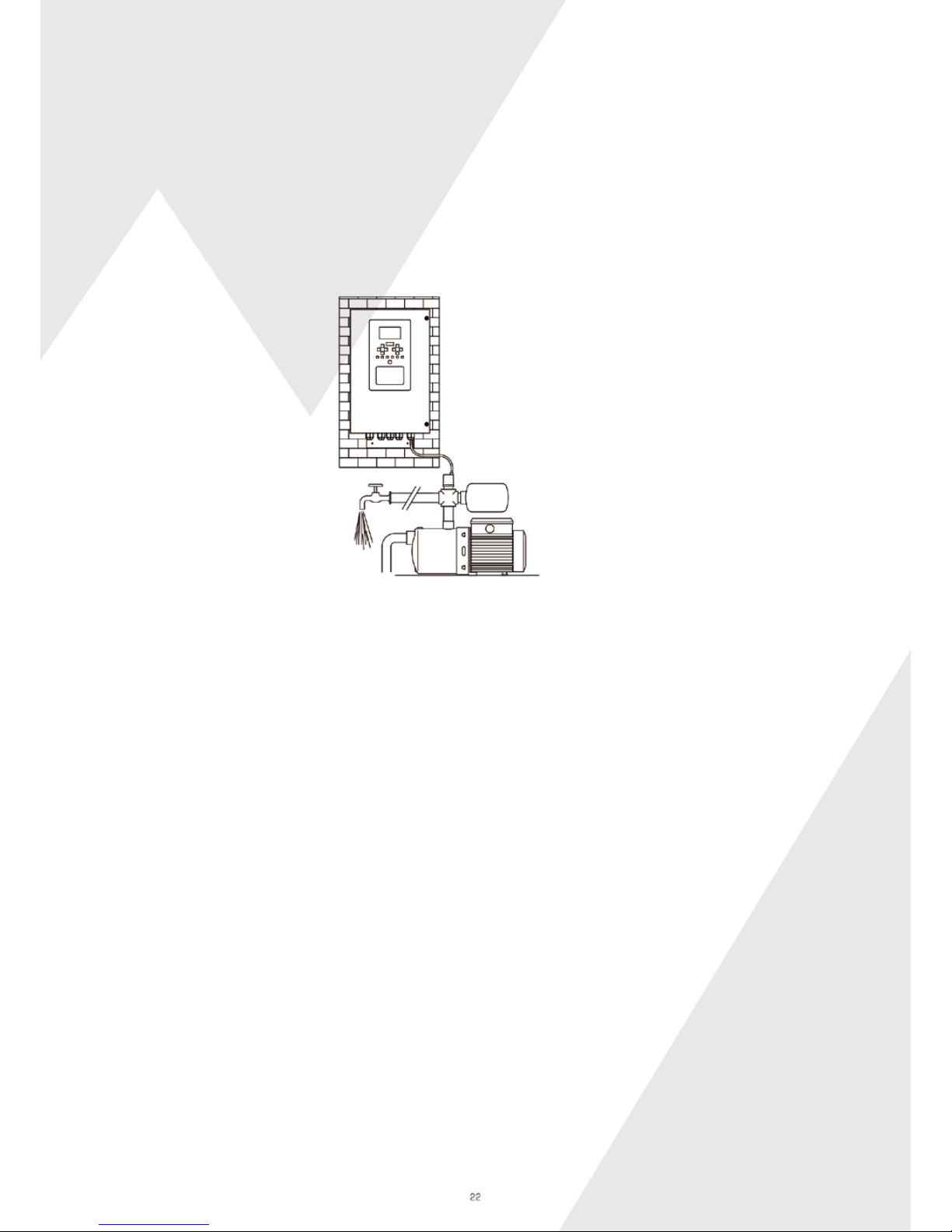
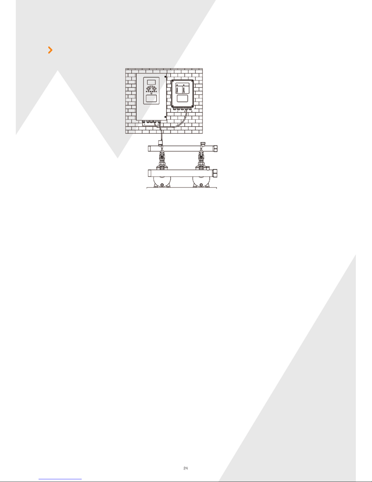
Install the device on a wall near the pump (fig. 1).
Connect the supplied pressure sensor, make the electrical connections and energize.
Arrange the use of an expansion tank sized according to the hydraulic characteristics of the system.
To startup the pump, follow the instructions that will appear in sequence on the display of the device:
- Language selection.
- Pump motor ampere setting.
- Minimum flow acquisition.
- Setting of the working pressure and restart pressure if different from factory setting: system pressure 3 bar restart pressure 1,5 bar.
- It is now possible to start the pump
FIG.1
Page 4
PUMPS ALTERNATION DURING CONTINUOUS OPERATION
AUTOMATIC RESTART AND ANTI-JAMMING FUNCTION
VARIABLE MASTER
If for any reason one or more pumps are working continuously, in order to guarantee uniform wear of the pumps, every sixty minutes of
continuous operation of a pump, a forced exchange will be made with another pump on stand-by.
The changeover respects the alternating sequence of all the devices.
In case of stopping due to a water shortage, the devices will automatically make 10 double attempts to rearm over the 24 hours
following the failure, each lasting approximately 5 seconds to allow the pumps and the system to reload if possible.
The user can try to rearm the devices at any time by pressing the Restart button.
If for any reason the pumps remain idle for 24 consecutive hours, the devices will carry out a start-up of the pump motor for about 5
seconds without affecting the normal operation of the pressure set.
In case of a temporary blackout, the pressure set will automatically rearm once the electricity returns.
In case of malfunctioning of the Master device, the system will transfer the operation to the Slave device immediately followingfrom
the Master. If the original Master device is reset, it will automatically be reintegrated into the system as a Slave device.
INSTALLATION AND SETUP
OPERATION
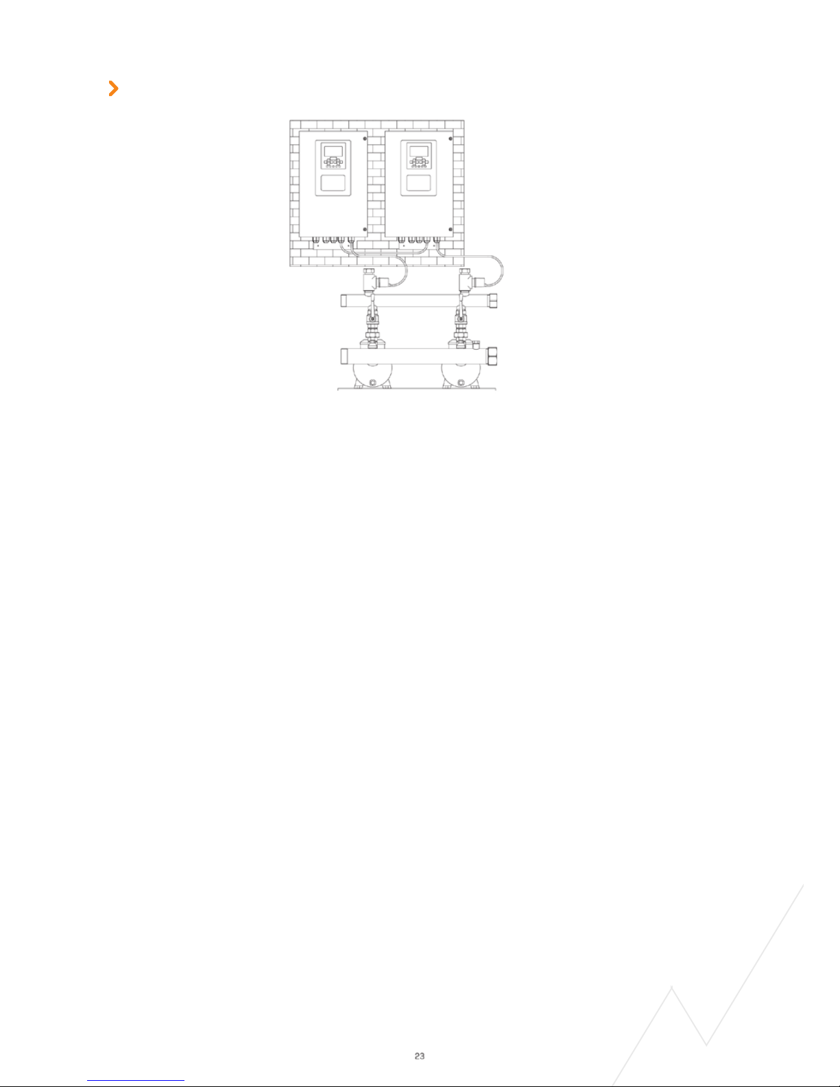
Connect the devices together using the serial port.
Program the Presscontrol Wall PRO selected as Master following the instructions on the display.
Enable communication on the Master Presscontrol Wall PRO that automatically will transfer the data to the other connected
Presscontrol Wall PRO units that will act as Slave devices.
You can now start the pressure set.
To change the system pressure value and restart pressure value, only act on the Master device even if the pump is running.
The system pressure value and restart pressure value set on the Master device will be automatically transferred to the Slave
devices.
The Master device controls the Slave devices and determines the group operation.
Initially, the pump on which the Master device is installed starts up first, but if the water demand is such that this pump is not
able to maintain the set system pressure value, the second pump on which the Slave device is installed automatically starts.
Each time the pumps stop, the second and/or third, fourth pump start depending on how many pumps are installed, to return to
the Master device and so on. The alternation of the startup and operation of the pumps that make up the pressure set ensures
uniform wear of the pumps, which results in a longer life of the unit.
PRESSURE SETS
Presscontrol Wall PRO is equipped with a communication interface that allows up to 4 devices to communicate
simultaneously.
Page 5
INSTALLATION AND SETUP
OPERATION
AUTOMATIC RESTART AND ANTI-JAMMING FUNCTION
Connect the Presscontrol Wall PRO to the electronic box using the serial port.
Program the Presscontrol Wall PRO according to the instructions on the display and enable communication.
On the Presscontrol Wall PRO and on the control panel of the control box the “Com” LED lights up.
You can now start the pressure set.
To change the system pressure value and restart value, act on the Presscontrol Wall PRO even if the pump is running.
Presscontrol Wall PRO controls the multi-pump electronic box and determines the operation of the set.
Initially, the first pump on which the inverter is installed starts up first, but if the demand for water is such that this pump is
unable to maintain the set system pressure value, then the second pump, third and fourth pump are automatically started,
depending on how many pumps are installed.
Every time the pumps stop, it will be the second, third and/or fourth pump to startup first, until finally returning to the first one
and so on.
The alternation of start-up and operation of the pumps that make up the pressure set, guarantees a uniform wear therefore
longer life of the pressure set.
In case of stopping due to a water shortage, the devices will automatically make 10 double attempts to rearm over the 24 hours
following the failure, each lasting approximately 5 seconds to allow the pumps and the system to reload if possible.
The user can try to rearm the devices at any time by pressing the Restart button.
If for any reason the pumps remain idle for 24 consecutive hours, the devices will carry out a start-up of the pump motor for
about 5 seconds without affecting the normal operation of the pressure set.
In case of a temporary blackout, the pressure set will automatically rearm once the electricity returns..
PRESSURE SETS
It is possible to control up to 4 pumps with a single Presscontrol Wall PRO, guaranteeing the alternation
of the pumps under inverter by an electronic box supplied as an option.
Page 6

PRESSCONTROL WALL PRO MODELS AND TECHNICAL FEATURES
MODELS T 9 T 12 T 16 T 19 T 23
Mains voltage
3 ~ 400 Vac 3 ~ 400 Vac 3 ~ 400 Vac 3 ~ 400 Vac 3 ~ 400 Vac
Acceptable voltage fluctuations
+/- 15% +/- 15% +/- 15% +/- 15% +/- 15%
Frequency (automatic recognition)
50 / 60 Hz 50 / 60 Hz 50 / 60 Hz 50 / 60 Hz 50 / 60 Hz
Voltage pump motor
3 ~ 400 Vac 3 ~ 400 Vac 3 ~ 400 Vac 3 ~ 400 Vac 3 ~ 400 Vac
Maximum pump motor current
9 A 12 A 16 A 19 A 23 A
Maximum pump motor power
3 kW - 4 HP 5,5 kW - 7,5 HP 7,5 kW - 10 HP 9,2 kW - 12,5 HP 11 kW - 15 HP
Soft “engine start”
Yes Yes Yes Yes Yes
Length of cable up to 80 m
Yes Yes Yes Yes Yes
Maximum operating pressure
25 bar 25 bar 25 bar 25 bar 25 bar
Adjustable system pressure
2 ÷ 12 bar 2 ÷ 12 bar 2 ÷ 12 bar 2 ÷ 12 bar 2 ÷ 12 bar
Adjustable restart pressure
1 ÷ 11 bar 1 ÷ 11 bar 1 ÷ 11 bar 1 ÷ 11 bar 1 ÷ 11 bar
Adjustable minimum flow
Yes Yes Yes Yes Yes
Maximum operating temperature
50 °C 50 °C 50 °C 50 °C 50 °C
Protection degree
IP54 IP54 IP54 IP54 IP54
Digital manometer
Yes Yes Yes Yes Yes
Digital ammeter
Yes Yes Yes Yes Yes
Dry running protection
Yes Yes Yes Yes Yes
Automatic restart
Yes Yes Yes Yes Yes
Anti-jamming function
Yes Yes Yes Yes Yes
Protection fuse
Yes Yes Yes Yes Yes
Short-circuit protection between phases
Yes Yes Yes Yes Yes
Short-circuit protection between phases and earth
Yes Yes Yes Yes Yes
Amperometric protection
Yes Yes Yes Yes Yes
Voltage surge protection
Yes Yes Yes Yes Yes
Over-temperature protection
Yes Yes Yes Yes Yes
Pressure sensor fault detection
Yes Yes Yes Yes Yes
Flow switch connection
Yes Yes Yes Yes Yes
Integrated NFC data transfer system
Yes Yes Yes Yes Yes
BMS protocol connection
Yes Yes Yes Yes Yes
Connection for float switch and level probe
Yes Yes Yes Yes Yes
Remote ON/OFF connection
Yes Yes Yes Yes Yes
Remote “Pump on” connection
Yes Yes Yes Yes Yes
Remote alarm connection
Yes Yes Yes Yes Yes
Communication between devices
Yes Yes Yes Yes Yes
TÜV SÜD Certification
Yes Yes Yes Yes Yes
Overall dimensions (L x H x W) and weight
270 x 470 x 180- 9kg
Note: The minimum and maximum values of the adjustable system pressure and adjustable restart pressure vary
depending on the pressure sensor.
 Loading...