

WaterTech PRESSCONTROL WALL PRO T9, PRESSCONTROL WALL PRO T12, PRESSCONTROL WALL PRO T19, PRESSCONTROL WALL PRO T23, PRESSCONTROL WALL PRO T16 User Manual
PRESSCONTROL
WALL PRO
VARIABLE FREQUENCY DRIVE FOR CONTROL AND PROTECTION
OF THE PUMP
PRESSCONTROL WALL PRO CAN OPERATE 400V THREE-PHASE PUMPS UP TO 15 HP.
Wall-mounted near the pump.
Varies the number of motor revolutions of the pump depending to the water withdrawal from the
system in order to maintain constant pressure and flow rate.
Allows to regulate the system pressure and the restart pump pressure.
Stops the pump in case of water shortage and protects it from dry running.
Is equipped with automatic restart in case of failure and anti-jamming function.
Can be installed on surface and submersible pumps.
Ensures energy saving.
Can be installed on surface pumps and submersible pumps.
Supplied with a 16 bar pressure sensor.
Standardly equipped with a communication interface to make pressure sets.
Standardly equipped with BMS protocol connection interface (Building Management System).
Standardly equipped with NFC technology for data transfer to the mobile phone.
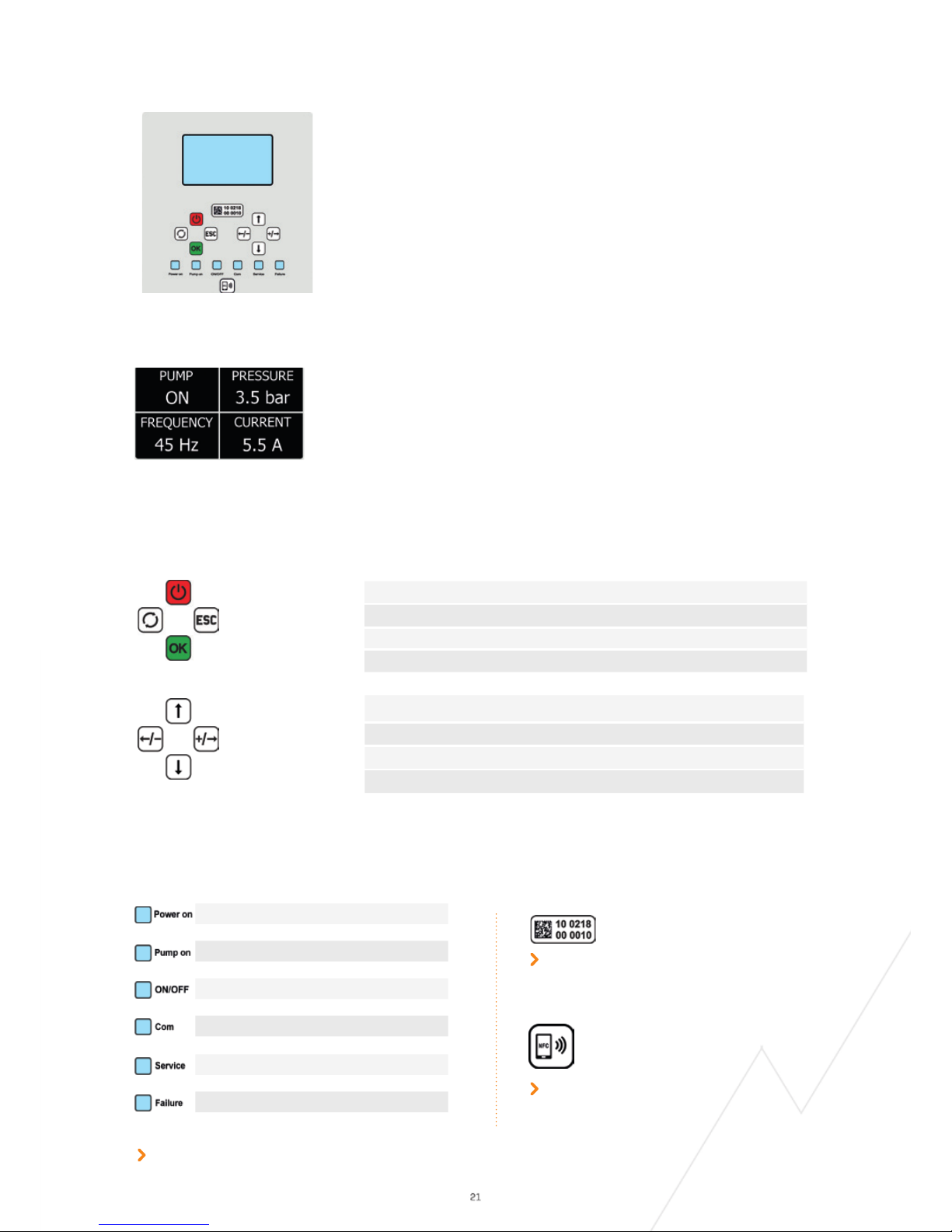
CONTROL AND SETTING PANEL
Setting up and starting Presscontrol Wall Pro is an extremely easy and intuitive
operation thanks to the large and bright display that shows the information and the
keyboard that allows you to enter and modify the pump operating parameters rapidly.
DISPLAY
KEYBOARD
SIGNALING
Serial number and data matrix of the device
The indicator LEDs of the main phases of operation of the device remain visible even when the display goes out to allow
the user to have the status of the system under control at all times.
Note: The Service Light does not preclude the system from operating. On the display, a description of the required action
will be displayed (e.g. recharging the pressure tank).
Data transmission with NFC technology.
Place mobile phone close to the icon for information transfer.
Device energized
Pump running
VFD On/Off
Communication between devices is active
Request for maintenance
Failure
The figure shows an example of displaying information divided into 4 quadrants:
1 - Pump status
3 - VFD operating frequency
2 - Real system pressure
4 - Current absorbed in Amperes
To save energy, the display will turn off one minute after the last action. To turn the
display on again, simply press any button on the keyboard.
ON/OFF BUTTON
Starts and stops the pump
ESC BUTTON
To exit the programming screen
OK BUTTON
To access programming and confirm data entry
RESTART BUTTON
For manual resetting in the event of a fault
UP ARROW
Menu scroll upwards
RIGHT ARROW
Menu scrolling to the right and to increase parameter values
DOWN ARROW
Menu scrolling downwards
LEFT ARROW
Menu scrolling to the left and to decrease parameter values
 Loading...