

Water Tec CP, WMXL, VXL, WXL, HXL Operating Manual
...
REVERSE OSMOSIS SYSTEMS
OPERATING MANUAL
MODELS:
CP / WMXL / WXL / VXL / HXL / HXXL / X
Water Tec International, Inc. Tucson, Arizona 85714 www.water-tec.com
Water Tec Int’l. Inc. Version 02A
2
10
3
This manual includes the most common components and installation specifications. Please keep
in mind that Water Tec manufactures many units to customer specifications. If you do not find the
information that you are looking for in this m anual, please contact your local Water Tec dealer.
TABLE OF CONTENTS
I INTRODUCTION TO REVERSE OSMOSIS
How Reverse Osmosis Works
The Membrane
Factors That Affect the Useful Life of a Membrane
Effects of Temperature on the Reverse Osmosis Units
Some Common Terms and Definitions Related to Reverse Osmosis
The Reverse Osmosis System
Purified Water Storage and Delivery
II REVERSE OSMOSIS COMPONENT IDENTIFICATION
III GENERAL SYSTEM DIAGRAMS
The Compact RO (CP)
The Wall Mount F.G. RO (WM)
The Wall Mount F.M. RO (WMXL)
The Vertical RO (VXL)
The Horizontal RO (HXXL)
The Horizontal RO (X)
IV REVERSE OSMOSIS SET-UP SPECIFICATIONS
V REVERSE OSMOSIS SET-UP
START-UP
TESTING PROCEDURES
VI MEMBRANE INSTALLATION
VII TROUBLE SHOOTING GUIDE
VIII REVERSE OSMOSIS PRE- TREATMENT
3
4
4
4
5
6
7-9
11
12
13
14
15
16
17
17
17- 18
18
19
20
Water Tec Int’l. Inc. Version 02A
3
INTRODUCTION TO REVERSE OSMOSIS
The application of reverse osmosis to the solution of problems in water treatment requires an understanding of the
basic mechanisms involved in the process, the limitations of reverse osmosis and the pre-treatment requirements.
HOW REVERSE OSMOSIS WORKS
Reverse Osmosis (RO) is the process in which water is forced by pressure through a semi -permeable membrane.
Water passes through the membrane while the dissolved and particulate materials are left behind. When pressure is
applied to the concentrated solution, water is forced through the membrane from the concentrated side to the diluted
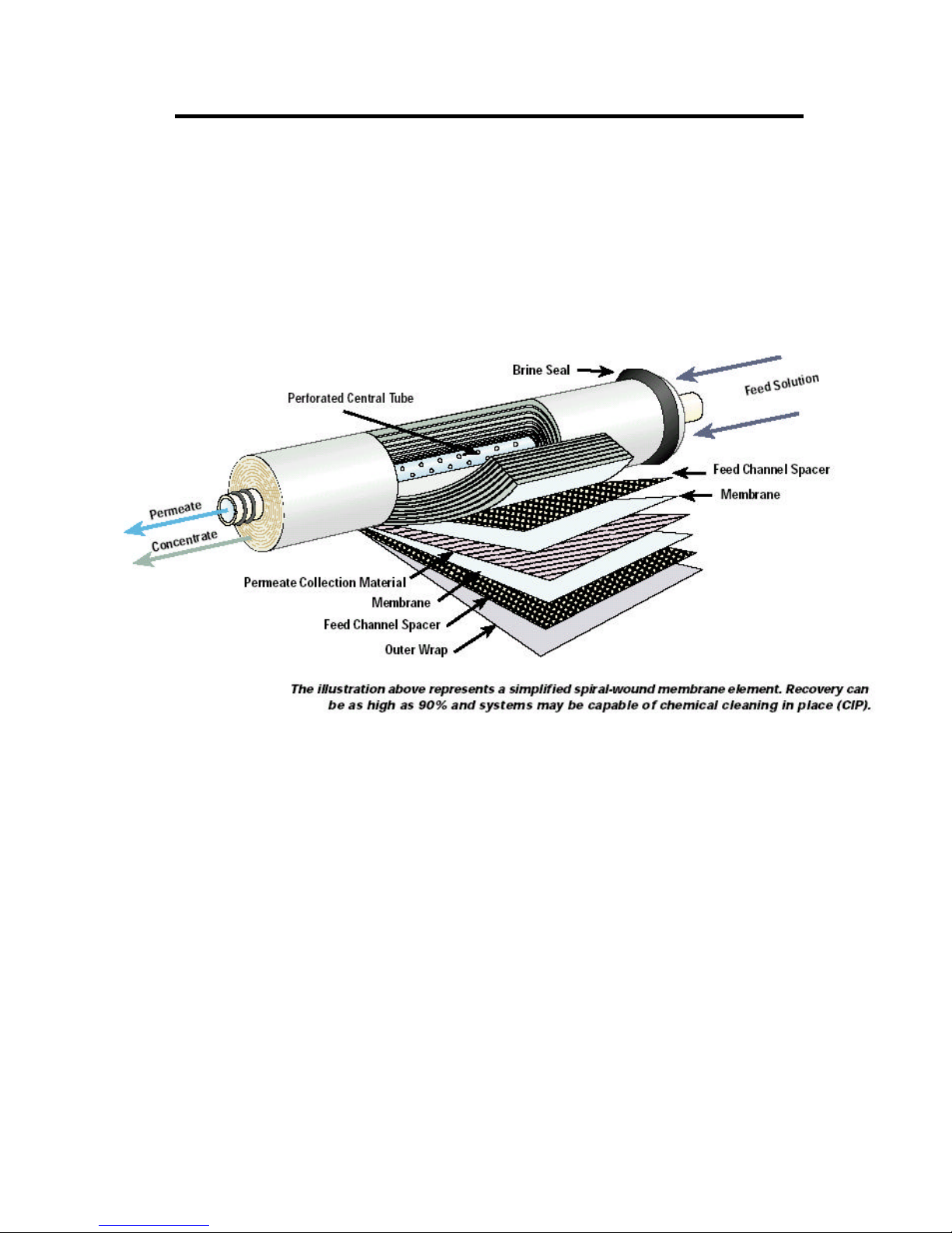
side. The spiral membrane is constructed of one or more membrane envelopes wound around a perforated central
tube. The permeate (product water) passes through the membrane into the envelope and spirals inward to the central
tube for collection.
THE MEMBRANE
Reverse Osmosis utilizes the unique properties of a semi-permeable membrane to allow fluid to pass while
restricting the flow of dissolved ionic material. With pressure applied to impure water on the side of such membrane
materials, pure water will pass through, leaving most of the impurities behind. The rejection of the dissolved ionic
material is a function of both molecular weight and ionic charge. For example, we can expect a nominal 90% rejection
of sodium chloride, which means that the product water passing through the membrane will have a concentration of
salt approximately one-tenth that of the feed water. The rejection of calcium carbonate (hardness) will be near 95%,
while most metallic salts will be rejected at a rate of approximately 98% to 99%.
The rejection of non-ionic or organic material is primarily by mechanical filtration. Most substances with a
molecular weight of over 100 will be completely rejected by an intact reverse osmosis membrane. Low molecular
weight organics, such as formaldehyde or phenol, can pass freely through an R.O. membrane, as can most dissolved
gasses. Oil, suspended solids and particulate matter are mechanically filtered, as are viruses, bacteria, pyrogen, and
larger organic molecules.
To carry the rejected material away from the membrane surface, the feed side of the R.O. membrane is
continually flushed with an excess flow, usually two to five times the product flow. This avoids clogging of the
membrane surface and reduces the tendency toward scale formation.
Water Tec Int’l. Inc. Version 02A
4
FACTORS THAT AFFECT THE OPERATION AND THE USEFUL LIFE OF THE MEMBRANE:
recovered by the R.O. membranes. Example: if you
There are five main factors that affect a reverse osmosis membrane:
1. PRESSURE: Excessive pressure tends to deform or compact the membrane. The compaction causes the
membrane to become less porous, thus decreasing the amount of product water.
2. HYDROLYSIS: Hydrolysis is the effect of chemicals in the feed water on the membrane. In general, this
happens when the water temperature is high and the pH is below 2.5 or above 7. For optimum life of the
membrane, the pH should be between 5 and 6.
3. BACTERIA: Bacteria, if allowed to grow on the membrane, will digest the top layer of the membrane and
reduce the ability of the membrane to reject salt.
4. TEMPERATURE: Temperatures above 95ºF are generally avoided because of the problems in the
membrane support structures and the accelerated compaction and hydrolysis rates. Membrane production
rates will go up with higher temperatures and down with lower temperatures.
5. SURFACE COATING OR FOULING: Surface Coating or Fouling is one of the most common problems with
reverse osmosis. It is the salts (calcium carbonate, etc.) that precipitate on the membrane. These salts plug
the pores and channels, reducing the water production rate.
EFFECTS OF TEMPERATURE ON THE REVERSE OSMOSIS UNITS:
In system design, it is very important to consider incoming water temperature. The units are rated for a product flow
at 77ºF (25ºC). The product flow reduces with lower temperatures. On an average, membranes will lose about 1.8%
production for every degree below 77ºF.
SOME COMMON TERMS AND DEFINITIONS RELATED TO REVERSE OSMOSIS:
FEED WATER - The raw water introduced into the R.O. modules.
PERMEATE WATER - The pure water produced by the R.O. membranes.
CONCENTRATE WATER - The wastewater that will not pass through the membrane and is directed to the drain.
MEMBRANE - Commonly referred to as the R.O. membrane without the membrane housing.
MODULE - Referred to as the complete membrane in the membrane housing.
G.P.D. - (gallons per day) This is the standard at which R.O. systems are sized. Example: a 1,000 GPD R.O.
system will produce 1,000 gallons of pure water in a 24-hour period. Systems are generally sized for
maximum amount of water used in a 24-hour period.
PPM - (parts per million) The method by which the quality of the R.O. products water is measured.
PERCENT RECOVERY- The amount of water that is
introduce 100 gallons of feed water into the membrane and you produce 60 gallons of
product water and 40 gallons of reject water, this is known as 60% recovery.
PERCENT REJECTION - The amount of salts or chemicals rejected by the R.O. membranes.
Water Tec Int’l. Inc. Version 02A

5
THE REVERSE OSMOSIS SYSTEM
The reverse osmosis unit is composed of two major parts: the high-pressure pump (200 PSI max) and the
membranes. The initial purified water production rate is measured at 200 PSI.
The system is carefully designed to make certain that minimum flow rates within the membranes are
maintained. This factor is important to the efficient operation of the membrane. The reason for this is as follows: as
pure water passes through the membrane under pressure, it leaves behind, at the membrane surface, a very high
percentage of dissolved substances originally present in the supply water. This “Boundary Layer” becomes more and
more concentrated through the system. The membrane tends to reject a constant percentage of “what it sees.” For
example, if the water in contact with the membrane is 100 PPM, then the purified water going through the membrane
at this point will be about 5 PPM (5%). At a location farther into the membrane, the water in contact with the
membrane surface could be at 500 PPM. The purified water going through the membrane at that point will be about
25 PPM (5%). By maintaining sufficient feed flow movement around the membrane, suspended matter tends to be
carried out of the system more effectively.
It should be noted, as discussed previously, that the less we concentrate the supply water in the reverse
osmosis unit, the better the product water quality is. In other words, the lower the operation ratio between water
recovery and reject water, the better the product water quality. For some applications, the economic benefits of better
product water quality far outweigh the extra cost of the reject water. An example of this is where reverse osmosis
water is to be subsequently passed through a de-ionization column for higher purity water. It appears that there are
longer-term benefits to be gained by operating at lower percent water recovery, particularly in reducing maintenance
to the systems, and minimizing precipit ation problems.
It is important to realize that the product water from a reverse osmosis system is delivered essentially at
atmospheric pressure, usually to a vented storage tank. In general, the unit cannot be operated by opening and
closing a valve at the product water line, unless a special pressure relief is provided. The reason for this is that the
high pressure in the system drives the water across the membrane surface. If, for some reason, the product line
were closed while the system was operating, the pressure would build up. The product side of the system is not
strong enough to withstand these high pressures and would fail, causing irreversible damage to the membrane
element! In reality, the plastic tubing on the permeate side normally wo uld not tolerate such high pressure.
Most standard membranes are capable of withstanding 400 PSI of “forward” pressure, i.e., from the high-pressure
side across the membrane surface to the product water side. This system is designed for a maximum of 200 PSI
unless otherwise specified on the unit itself. However, the product water side cannot tolerate “back” pressure, i.e.,
in the direction from the product water side to the supply water side. The maximum backpressure should be no more
than 3 or 4 feet head of water (5 to 6 PSI). In order to prevent damage to the membranes from this source, a check
valve is placed, in pressure tank applications, on the product water line, so that when the system shuts down,
backpressure is effectively sealed off. This safety device should never be bypassed.
When a reverse osmosis system is shut down, the supply water is in a “resting” state over the membranes, i.e.,
almost no pressure across the membranes. During this time water may bleed through the product side. This water
tends to have about the same mineral content as the supply water. As a result, the first water sample obtained after
start-up is higher in mineral content, until the system flushes out this water after a few seconds.
The quality of purified water produced by reverse osmosis is roughly a constant percentage of the feed water. For
example: when the feed water is entering at 50 PPM, the purified water may be between 2 to 5 PPM (90-95%
rejection of dissolved minerals). When the feed water is entering at 500 PPM, the product water would be from 25 -50
PPM (90-95% rejection of dissolved minerals). Usually a conductivity meter or “total dissolved solids” meter is used to
measure the mineral content of the product water.
Water Tec Int’l. Inc. Version 02A

6
PURIFIED WATER STORAGE AND DELIVERY SYSTEM
As previously discussed the R.O. product water is almost always delivered to an atmospheric storage tank.
Normally, such a storage tank is sized to provide sufficient water to cope with the number of hours of continuous use,
e.g., 8 hours, and 16 hours. In an exactly balanced system, the reverse osmosis unit would be running continuously.
However, in practice, demand fluctuates. A liquid level switch, which is provided with the R.O. unit, should be installed
at the full line of the tank. The liquid level switch turns off the R.O. when the tank is full. This way the unit only runs
when the tank is being emptied. Other types and styles of liquid level switches are available from your authorized
Water Tec distributor.
The purified water in the storage tank is distributed to the use points by means of a moderate pressure high
capacity centrifugal pump. This pump can be provided with a demand pressure switch, which turns on the pump
when it senses a drop in pressure (opening a faucet at the user point). Alternatively, it can be operated continuously,
with a pressure relief system to recirculate water back to the tank, when there is no demand. Such distribution
systems give very satisfactory service, because it avoids the detrimental repetitive on-off condition for the pump
motor. The pumps must never be allowed to run dry, since this will rapidly deteriorate the shaft seal and cause the
seal to leak. To prevent this the storage tank should be fitted with a low level switch, which shuts down the
distribution pump if the water level in the tank gets dangerously low.
Water Tec Int’l. Inc. Version 02A
 Loading...