

Water Street Brass Mortise Entry Handle Set Installation Instructions Manual
Mortise Entry Handle Set Installation Instructions
Pan Head
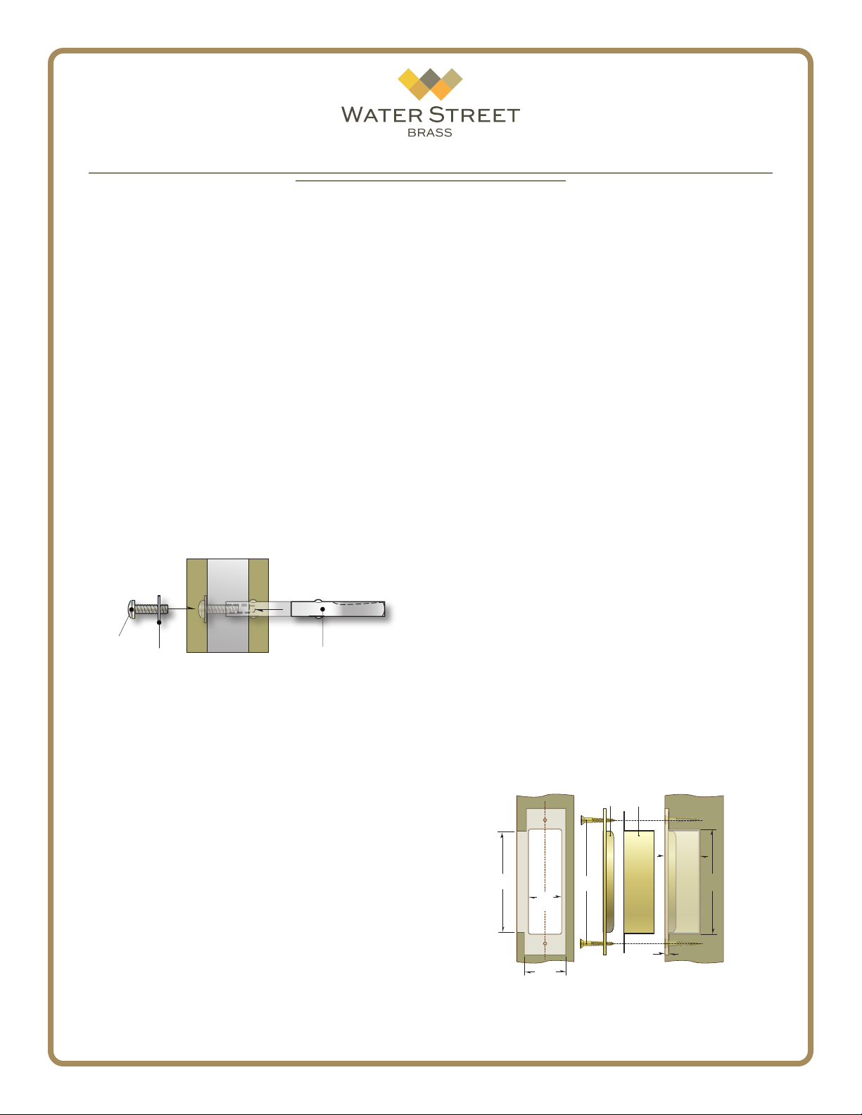
Strike
Screws
Strike
Plate
Door Jamb
Box
Height
Dust
Box
1/8”
Box
Depth
Box
Width
Face
Width
Lip
Height
These instructions are for the installation a mortise
lock entry set. The hardware will work with either a
door knob or lever.
Prepare the Door
1. If your door has not already been prepared for
your lock installation, do so by using the templates
provided for your specic lock model. Be sure to conrm the proper backset, function and handing for your
door prior to any drilling or mortising.
2. Install the mortise lock body in the door using the
screws provided. Do not install the lock body face plate
at this time.
Install the Hardware
3. Insert the half spindle into the lock body from the
interior side of the door. The set screw groove should
be on the top - away from the oor. From the exterior
side of the door, secure the spindle with the washer
and screw provided.
Exterior Interior
Screw
Washer Spindle
4. From the exterior side of the door, measure the
distance to the middle of the lock body. Cut the thumb
piece stem to this length.
5. Position the exterior plate & pull assembly onto
the door. Use the blank key provided to thread the
mortise cylinder into the lock body - this will help you
hold the plate in place during installation.
6. Mark the location of the pull legs on the door and
drill 9/32” diameter holes through for the mounting
bolts. The upper bolt must be counter-sunk into the
door so the head does not protrude above the door
surface. A re-enforcing grommet is provided but it
must be completely recessed in the door.
From the interior side of the door, install the
mounting bolts as shown in the diagram. When the
plate is securely on the door, install the bolt cover by
hand threading it onto the mounting plate.
7. Check the function of the mortise cylinder and
the thumb piece to make sure the lock works properly.
Lock
Body
Groove on top,
away from oor.
When satised, lock the cylinder in place by tightening
the cylinder retention screws from the edge of the
door.
9. Position the interior plate on the door, sliding the
thumb turn tailpiece into the lock body and the knob
or lever onto the spindle. Do not tighten the set screw
at this time.
Assure the plate is parallel to the door edge that the
thumb turn and knob/lever works without jamming.
When satised with the plate position, mark the surface mount screw hole locations on the door and drill
1/16” pilot holes for the surface mount screws.
Note: the pilot holes are important to guide the screws
in straight and to prevent the wood from splitting.
10. Complete the installation of the interior plate
assembly. Firmly secure the set screw in the knob or
lever to hold the spindle rmly.
11. Carefully install the surface mount screws on both
the interior and exterior plates. DO NOT use a power
drill to install the surface mount screws.
You can now also attach the mortise lock face plate.
Door Jamb
12. Carefully measure the jamb to determine the exact
location that the lock bolt will land when the door is
fully closed. Mark the location. Using the strike plate
as a template, outline the shape and begin to mortise
the door jamb 1/8” deep to accept the strike and lip.
Finally, mortise the jamb to the proper depth to
accept the dust box.
1
41080 - Rev. 2017 ©Water Street Brass - All rights reserved
Drawing not to scale.
Components may appear dierently than
depicted; for reference only.
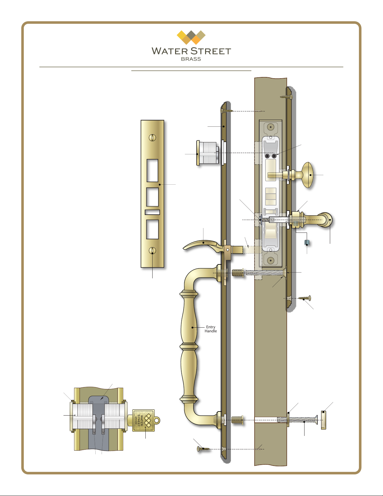
Mortise
Cylinder
Mortise Lock
Escutcheon
Face Plate
Thumb Piece
Plate
Exterior
Pan Head
Screw
and Washer
Cut stem
to length
Door
Lock
Body
Interior
Clylinder
Retention
Screws
Nylatron
Washer
Set Screw
Mortise
Thumb Turn
Lever or Knob
Face Plate
Key x Key Option
13. If your hardware uses two cylinders
instead of an interior thumb turn, the
cylinders should be inserted into the both
plates so that they each engage the lock
mechanism, making sure the cams on the
cylinders do not interfere with one another,
as shown.
Depending on the thickness of your
door, cylinder blocking rings may be needed
to achieve proper spacing.
Mortise Cylinder
Blocking Ring
(Reference)
Mortise Cylinder
Lock Body
Blank Key
(Use to screw in cylinder)
Screw
Oval Head
Wood Screw
Entry
Handle
Re-enforcing
Grommet
(Optional)
Ø 1/16”
Pilot Holes
Bolt head must
be recessed below
door surface as shown.
Oval Head
Wood Screw
Bolt Cover
Mounting
Plate
1/4-20 Bolt
Bolt Cover
Cylinder Cams
(Maintain A Gap)
2
41080 - Rev. 2017 ©Water Street Brass - All rights reserved
 Loading...