

Water Street Brass 41035 Quick Start Manual
Tubular Latch x Mortise Bolt Installation
Sectional Trim
Prepare the Door
1. Establish the desired latch height on your door.
Using the provided templates for your lock or latch,
mark hole locations on the door.*
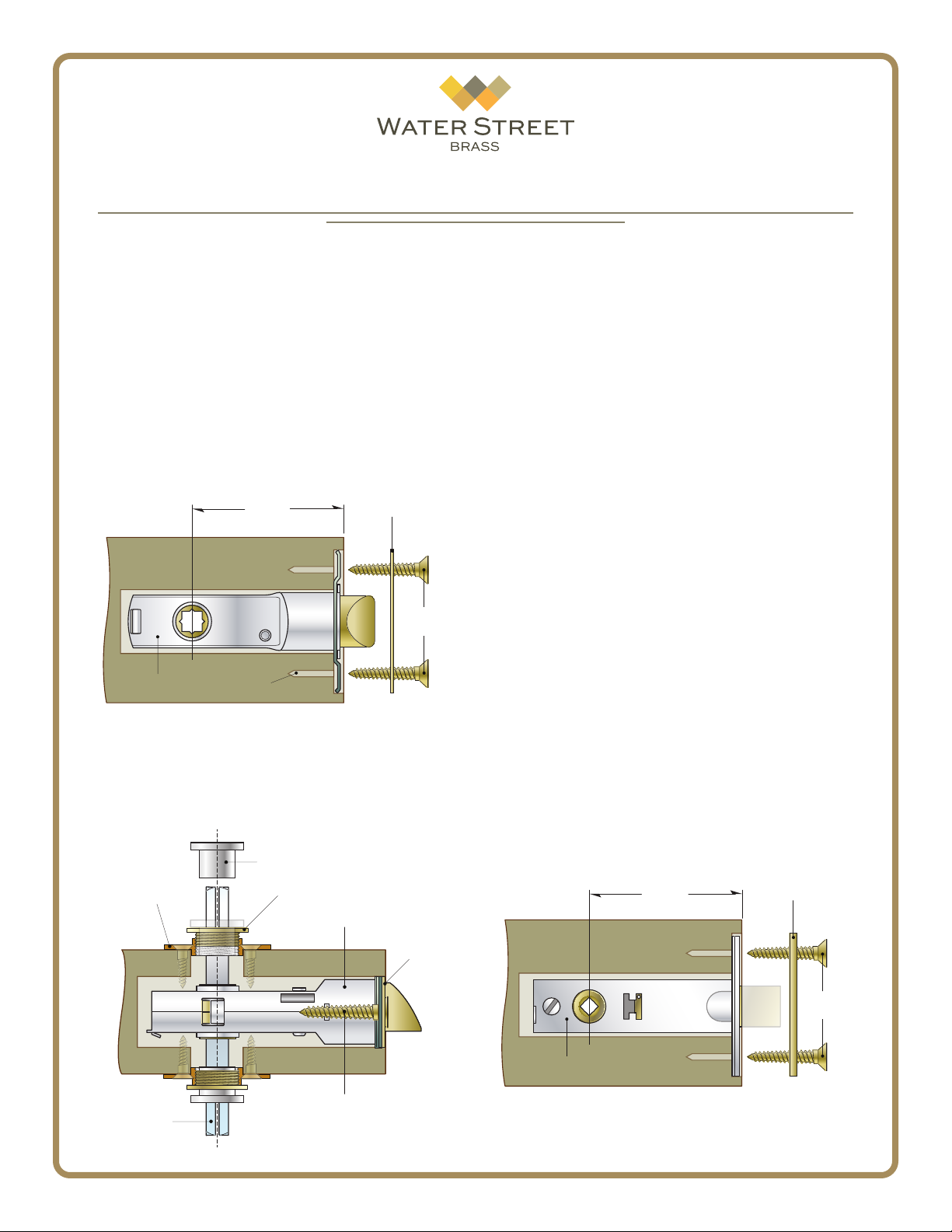
2. Using the drill & bore sizes specied on the template, carefully drill the door. On the door edge, mark
and drill two pilot holes for the installation screws.
Install the Latch
3. Install the latch body and face plate into the door
and secure loosely with the screws provided. Do not
tighten completely at this time.
Backset
Latch Body
4. Insert the spindle
Pilot Holes
through
the latch body as shown.
Position a rosette mounting plate with a threaded hub
on both sides of the door. Insert the two alignment
bushings into the hubs and snug the mounting plates
rmly against the door surface.
Alignment Bushing
Rosette
Mounting Plate
Threaded Hub
Latch Body
Face Plate
Face Plate
Screws
Face
Plate
5. Tighten the latch face plate screws. When satised that the latch is rmly in place and level, mark the
screw hole locations for the rosette mounting plates.
Drill pilot holes and proceed to ax the plates to the
door surface with the screws provided.
As a nal check, remove the alignment bushings
and place a lever or knob on the spindle. Check that
the latch functions properly. If there is any binding
or sticking, slight adjustments to the latch face plate
or rosette mounting plates may be necessary. Once
satised that the latch is working properly, remove the
threaded hubs and spindle.
6. You can now install the rosettes by locating them
over the rosette mounting plates. Firmly secure the
threaded hubs using the tool provided. Take care not
to scratch or mar the rosette surfaces when installing.
7. Complete the installation by centering the spindle
in the latch body. To prevent binding, we recommend
the grooves in the spindle be facing up, away from
the set screws.
Place the levers or knobs onto the spindle with
the Nylatron washers located on the bases. Seat the
lever or knob so that it sits at against the washer and
rosette face. Using the hex key wrench provided, rmly tighten the set screws so that they seat within the
spindle grooves. When properly seated, there should
be no gaps or excessive play in the levers or knobs.
Install the Mortise Bolt
8. In the same manner as the latch, install the mortise
bolt and face plate into the door and secure with the
screws provided.
Backset
Face Plate
Spindle
Face Plate
Screws
Mortise Bolt Body
1
41035 - 2016 ©Water Street Brass - All rights reserved
Face Plate
Screws
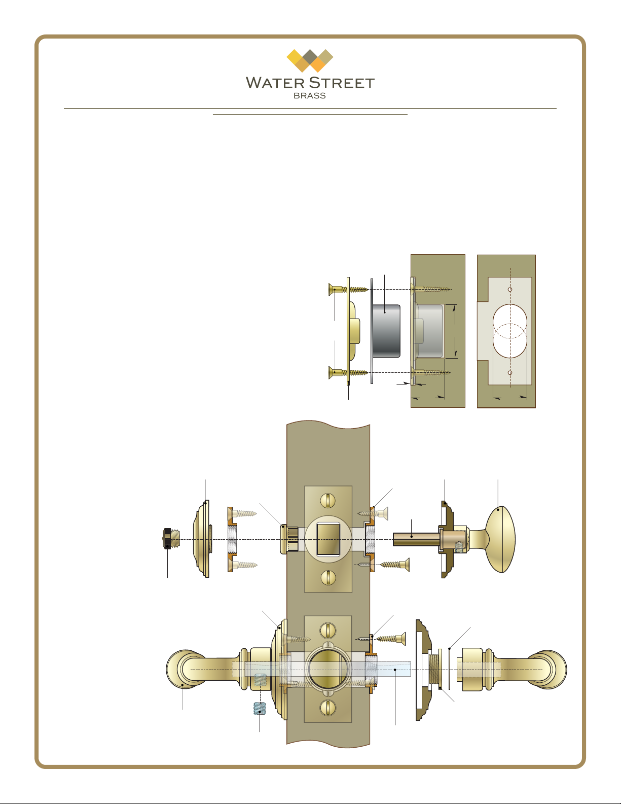
9. On the interior side of the door, center the mortise
Strike
Screws
3/32”
Dust Box
Strike Plate
Door Jamb
1-3/8”
7/8”
7/8”
bolt mounting plate over the through hole. Secure the
plate in position with the two screws provided.
10. Slide the thumb turn stem into the mortise bolt
body and hand thread the mortise bolt trim plate onto
the mounting plate. If the trim plate does not align
with the mounting plate, you may need to loosen the
screws and adjust the location slightly.
Note: The thumb turn stem is designed to t doors in excess of 4” thick. Measure and cut this stem so that it reaches to the approximate center of the mortise bolt body.
11. If your emergency egress trim is the screw on variety,
repeat step 9 on the exterior side of the door.
If your trim is the optional tap in variety, use a rubber mallet to gently tap the emergency egress collar
into the through hole on the exterior side of the door.
Hand screw the emergency egress access button
into the collar - do not over tighten.
Door Jamb
12. Carefully measure the jamb to determine the exact
location that the latch strike and lock bolt land when
the door is fully closed. Mark the locations. Using the
strike plate as a template, outline the shape and begin
to mortise the door jamb to accept the strike.
Mortise the dust box cavities as shown here. If
using a full lip latch strike, the dust box will be smaller;
measure carefully and install.
After installation, if the latch does not fully engage
with the strike, loosen the screws and adjust slightly.
*Note: The mortise bolt may be
located above or below latch.
The spacing may vary from the
template so conrm the latch
placement and all measurements
before preparing the door.
Emergency Egress
Access Button
Illustrations not to scale; for reference only.
Emergency Egress
Trim Plate
Lever
or Knob
Exterior
Optional
Tap In Emergency
Egress Collar
Rosette
Set Screw
1-3/4” Door
2
Interior
Moritse Bolt
Mounting
Plate
Actuator
Stem
(Cut to size)
Rosette
Mounting
Plate
Spindle
(Groove Up)
Moritse Bolt
Trim Plate
Nylatron Washer
Threaded
Hub
Mortise Bolt
Thumb Turn
41035 - 2016 ©Water Street Brass - All rights reserved
 Loading...