

Water Street Mortise Passage Set Installation Instructions Manual
Mortise Passage Set Installation Instructions
These instructions are for the installation a mortise
lock privacy set. The hardware will work with either
door knobs or levers, depending on the lock specied.
From this point forward, we’ll just refer to levers.
Prepare the Door
1. If your door has not already been prepared for
your lock installation, do so by using the templates
provided for your specic lock model. Be sure to conrm
the proper backset, function and handing for your door
prior to any drilling or mortising.
2. If your plates are using through bolts, use the
provided template to mark and drill the door for the
bolts. If using surface mount screws, you will position
the plates as installing and mark the screw positions.
3. Install the mortise lock body in the door using the
screws provided. Do not install the lock body face plate
at this time.
Install the Hardware
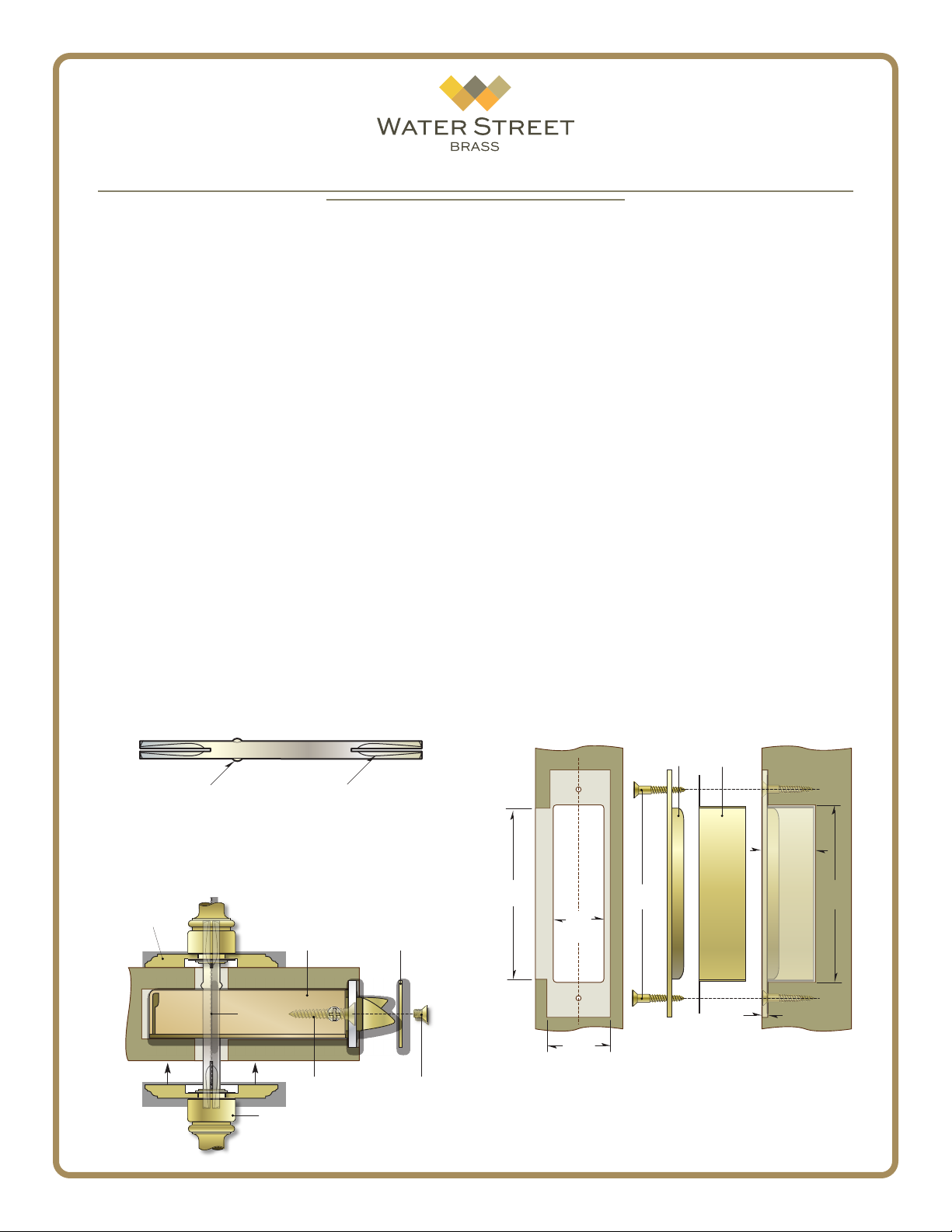
4. Insert the spindle into the lock body and center
it. The security notches should be on the exterior side
of the door and the set screw grooves should be at the
bottom, facing the oor.
Straight Spindle - Bottom View
Next align the interior plate so the spindle engages the lever. Adjust the plates to sit square with the
door edges.
Loosely install the through bolts as shown in the
assembly illustration. Do not tighten these screws yet.
6. Adjust the spindle position if needed, then rmly
tighten the interior lever set screw.
7. Test the function of the levers. When satised that
they are working properly, rmly tighten the through
bolting to hold the plates in place.
NOTE: Do not use power tools to tighten these
screws! Hand tighten the through bolts only.
8. Complete installation by attaching the mortise
lock face plate.
Door Jamb
9. Carefully measure the jamb to determine the exact
location that the lock bolt will land when the door is
fully closed. Mark the location. Using the strike plate
as a template, outline the shape and begin to mortise
the door jamb 1/8” deep to accept the strike and lip.
Finally, measure the dust box and mortise the jamb to
the proper depth and width.
Security Notch Set Screw Groove
5. First position the exterior plate on the door by
holding the spindle in place and sliding the lever/plate
assembly into position. Tighten the set screw in the
lever to keep the spindle centered.
Escutcheon Plate
Spindle
Mortise
Lock Body
Lock Body
Installation
Screws
Lever Or Knob
(Attached To Plate)
Face
Plate
Face Plate
Screws
41072 - August 2015 ©Water Street Brass - All rights reserved
Strike
Lip
Height
Box
Width
Face
Width
1
Strike
Screws
Plate
Dust
Box
1/8”
Door Jamb
Box
Depth
Box
Height
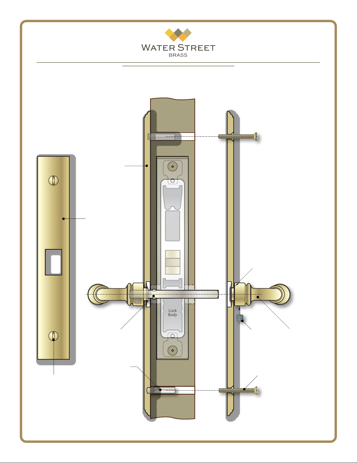
Assembly Cross Section
Escutcheon
Plate
Mortise Lock
Face Plate
Exterior
Door
Interior
Nylatron Washer
Face Plate
Screw
Spindle
(Grooves Down,
Stops On Exterior)
Undermount
Attachment
41072 - August 2015 ©Water Street Brass - All rights reserved
Lock
Body
Set Screw
Lever or Knob
Through
Bolt
Drawing not to scale.
Components may appear dierently
than depicted; for reference only.
2
 Loading...