

Air to Water
Split DHW
Integrated type
DESIGN & TECHNICAL MANUAL
INNOVATIVE SOLUTION OF DOMESTIC HEATING
DTW_SDI003E_01

2. HYDRAULIC UNIT
DTW_SDI003E_01--CHAPTER02
2015.02.18
COMFORT SERIES_Single phase type:
WGA050DG
WGA100DG
HIGH POWER SERIES:
WGG140DG
WGYK160DG9

HYDRAULIC UNIT
WG
050-160DG
HYDRAULIC UNIT
WG
050-160DG
CONTENTS
HYDRAULIC 22 UNIT
12 FEATURES
22222222222222222222222222222222222222222222222222222222222222222222222222222222222222222222222222222222222222222
HU01 - 01
22 SPECIFICATIONS
2222222222222222222222222222222222222222222222222222222222222222222222222222222222222222222222222
HU01 - 03
2-12 TECHNICAL SPECIFICATIONS
2222222222222222222222222222222222222222222222222222222222222222222222222222
HU01 - 03
2-22 ELECTRICAL SPECIFICATIONS
22222222222222222222222222222222222222222222222222222222222222222222222222
HU01 - 05
32 DIMENSIONS
222222222222222222222222222222222222222222222222222222222222222222222222222222222222222222222222222222222222
HU01 - 08
3-12 DIMENSIONAL DRAWING
2222222222222222222222222222222222222222222222222222222222222222222222222222222222222
HU01 - 08
3-22 INSTALLATION PLACE
222222222222222222222222222222222222222222222222222222222222222222222222222222222222222222
HU01 - 09
42 PIPING DIAGRAM
2222222222222222222222222222222222222222222222222222222222222222222222222222222222222222222222222
HU01 - 10
52 WIRING DIAGRAM
22222222222222222222222222222222222222222222222222222222222222222222222222222222222222222222222
HU01 - 11
5-12 WIRING DIAGRAM
22222222222222222222222222222222222222222222222222222222222222222222222222222222222222222222222222
HU01 - 11
5-22 EXTERNAL CONNECTION DIAGRAM
2222222222222222222222222222222222222222222222222222222222222222
HU01 - 14
62 HYDRAULIC PERFORMANCE
2222222222222222222222222222222222222222222222222222222222222222222
HU01 - 16
6-12 STATIC PRESSURE DROP UNIT
22222222222222222222222222222222222222222222222222222222222222222222222222
HU01 - 16
72 SAFETY DEVICES
222222222222222222222222222222222222222222222222222222222222222222222222222222222222222222222222
HU01 - 17
82 STANDARD ACCESSORIES
222222222222222222222222222222222222222222222222222222222222222222222222
HU01 - 18

- (HU01 - 01) -
Hydraulic unit / Split DHW integrated
HYDRAULIC UNIT
WG
050-160DG
HYDRAULIC UNIT
WG
050-160DG
FEATURES12
MODEL : WGA050DG
WG
A100DG
WG
G140DG
WGYK160DG9
COMPACT HYDRAULIC UNIT DESIGN with DHW TANK
INTELLIGENT CONTROL
2-zone individual control *
z
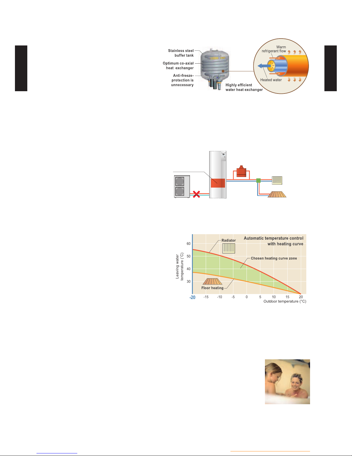
HIGH EFFICIENT CO-AXIAL
HEAT EXCHANGER
Co-axial Heat Exchanger
HIGH EFFICIENCY CLASS A PUMP
HIGH PERFORMANCE
DHW TANK 190L
Energy saving pump with
constant volume or pressure
adjustment function.
- DHW Production with
coil heat exchanger
to optimise the DHW
performanc e.
- Quick temperature rise
due to a big exchanger
surface.
- Parallel DHW and
space heating
operation possible.
Class
A
Stylish space saving solution with
built-in DHW tank
Hydraulic unit
DHW Tank 190L
648 mm
698 mm
1,840 mm
Installation
space area
about
50
%
reduction
*: Optional parts are required
Hydraulic unit
Radiator
Floor heating
Valve
Pump
Outdoor unit
50°C
Over
possible
~40°C
2nd Circuit Kit
- (HU01 - 02) -
Hydraulic unit / Split DHW integrated
HYDRAULIC UNIT
WG
050-160DG
HYDRAULIC UNIT
WG
050-160DG
HIGH RELIABILITY
High durability
z
Corrosion protected
•
No ow switch and no lter necessary
•
Easy installation and maintenance
z
All hydraulic safety and controlling components built in, no additional selection required
•
Easy access for maintenance operations
•
Refrigerant pump down operation
•
Emergency operation
z
System can be continuously supplied
hot water by built in back up heater or
boiler as emergency, even if an error is
occurred.
OTHERS
Automatic heating curve control
z
Automatic temperature regulation in
accordance with heating curve (Depend on
heating terminal and outdoor temperature)
Cooling operation is possible*
z
*: Optional parts are required
Anti-Legionella function
z
The growth of Legionella in DHW Tank is suppressed and safe and clean hot
water is supplied at all times.
Possible to docking the boiler or electric heater for backup
z
Radiator
Outdoor unit Hydraulic unit
Boiler*1
Backup heater*2
Floor heating
*1: When additional boiler connected
*2: WGY model only

- (HU01 - 03) -
Hydraulic unit / Split DHW integrated
HYDRAULIC UNIT
WG
050-160DG
HYDRAULIC UNIT
WG
050-160DG
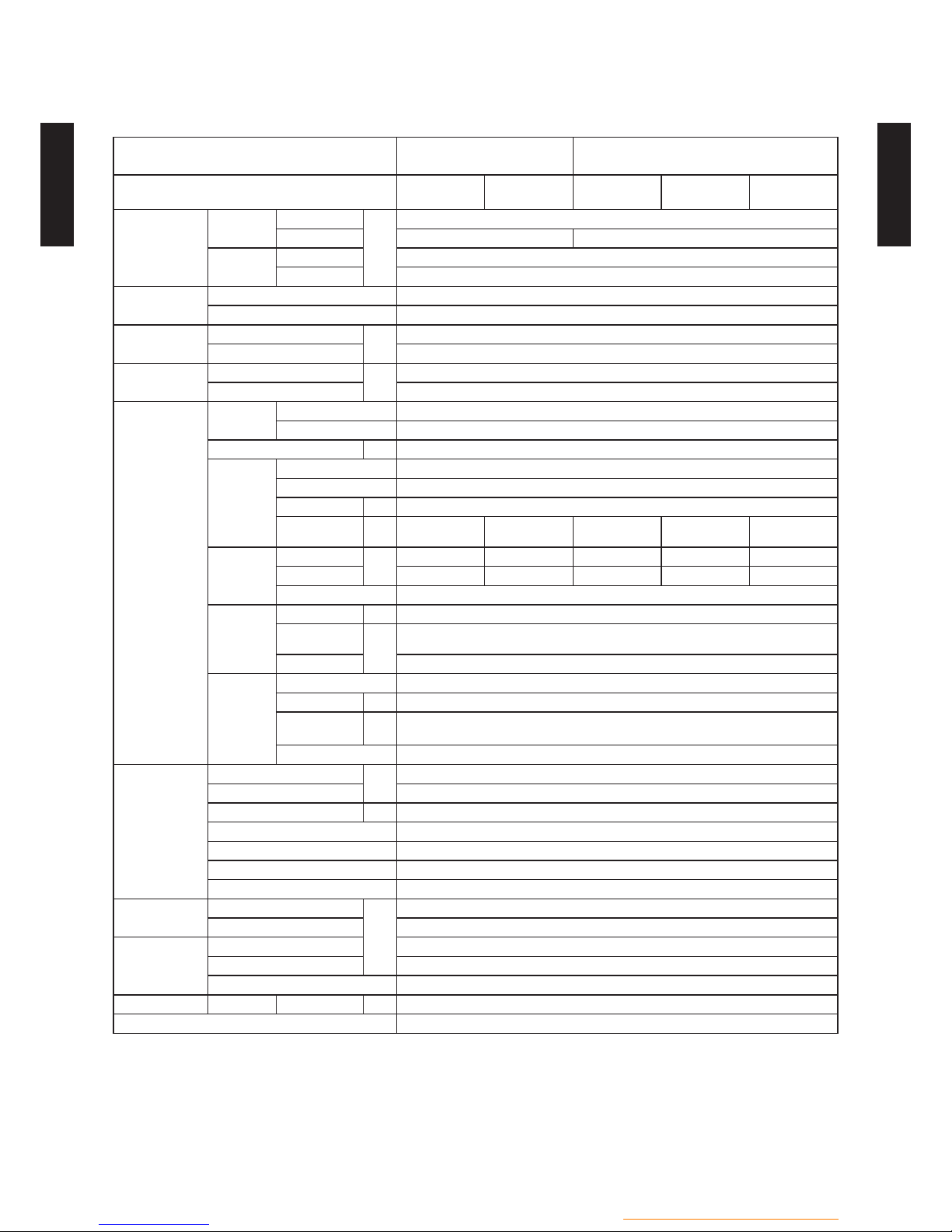
SPECIFICA TIONS22
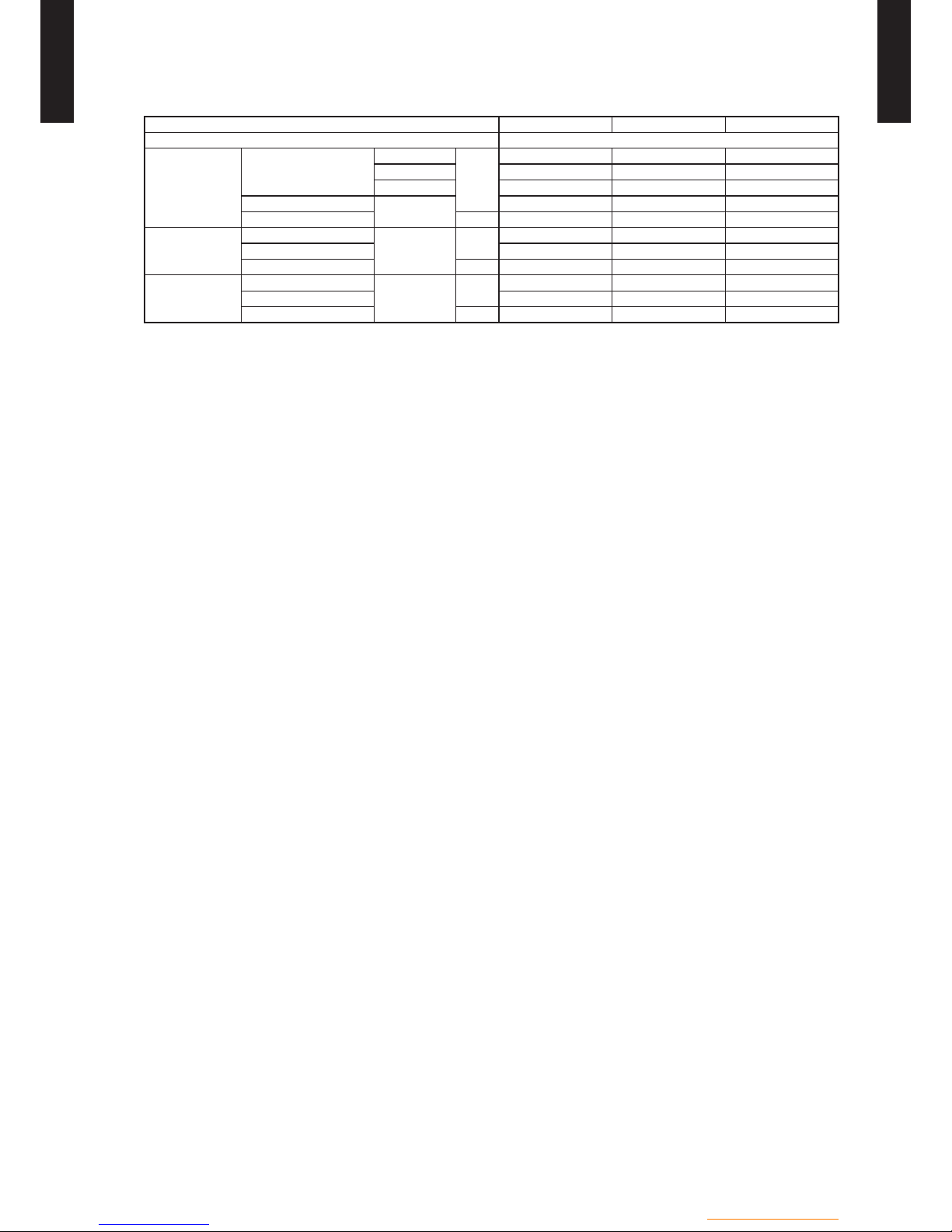
TECHNICAL SPECIFICATIONS2-12
COMFORT SERIES
Model name (Hydraulic unit)
WGYA050DG6
WGHA050DG
WGYA100DG6
WGHA100DG
Model name (Outdoor unit)
WOYA060LFCA
WOHA060LFCA
WOYA060LFCA
WOHA060LFCA
WOYA080LFCA
WOHA080 LFCA
WOYA100LFTA
WOHA100LFTA
Input power
Enclosure
Heating
Rated
kW
0.08
Max. *1 6
DHW
Rated 0.08
Max. *3 1.50
Casing
Colour White
Material 8/10mm DC01 + EZ (5µ)
Dimensions
(H x W x D)
Net
mm
1,840 x 648 x 698
Gross 2,005 x 770 x 872
Weight
Net (Empty/Full of water)
kg
WGY: 152/366, WGH: 150/364
Gross WGY: 175, WGH: 173
Main components
Pump
Type Water cooled
Speed setting Variable pressure / Constant pressure
Input power W 70 *2
Water side
Heat
exchanger
Type Double-tube
Q’ty 1
Water volume l 16
Water ow
rate Min.
l/h 490 650 810 1080
Water ow
rate Nom.
Heating
l/h
780 1040 1300 1733
Cooling 690 897 1225 1467
Insulation material polyurethane
Expansion
vessel
Volume l 12
Max. water
pressure
bar
4.0
Pre pressure 1 bar (+/-20%)
DHW tank
Type Enamel coated steel
Water volume l 190
Max.water
pressure
bar 10
Anti-corrosion Titanium anode (ACI)
Water circuit
Piping connections diameter
mm
ø25.4 (ø1 in.)
Piping ø25.4 (ø1 in.)
Safety valve bar 3
Manometer Yes
Drain valve / Fill valve Yes
Distribution valve Yes
Air purge valve Yes
DHW connection
Piping connection diameter
mm
ø19.05 (ø3/4 in.)
Piping ø19.05 (ø3/4 in.)
Connection pipe
(Refrigerant circuit)
Liquid side diameter ø6.35 (ø1/4 in.) ø9.52 (ø3/8 in.)
Gas side diameter ø12.70 (ø1/2 in.) ø15.88 (ø5/8 in.)
Method Flare
Operation range Waterside Heating °C 8 to 55
Pump rank A
*1: With electric back-up heater.
*2: The value is at Full speed and full ow.
*3: With electric DHW heater.
- (HU01 - 04) -
Hydraulic unit / Split DHW integrated
HYDRAULIC UNIT
WG
050-160DG
HYDRAULIC UNIT
WG
050-160DG
HIGH POWER SERIES
Model name (Hydraulic unit)
WGYG140DG6
WGHG140DG
WGYK160DG9
WGHG140DG
Model name (Outdoor unit)
WOYG112LCTA
WOHG112LCTA
WOYG140LCTA
WOHG140LCTA
WOYK112LCTA
WOHK112LCTA
WOYK140LCTA
WOHK140LCTA
WOYK160LCTA
WOHK160LCTA
Input power
Enclosure
Heating
Rated
kW
0.08
Max. *1 6 9
DHW
Rated 0.08
Max. *3 1.50
Casing
Colour White
Material 8/10mm DC01 + EZ (5µ)
Dimensions
(H x W x D)
Net
mm
1,840 x 648 x 698
Gross 2,005 x 770 x 872
Weight
Net (Empty/Full of water)
kg
WGY: 152/366, WGH: 150/364
Gross WGY: 175, WGH: 173
Main
components
Pump
Type Water cooled
Speed setting Variable pressure / Constant pressure
Input power W 70 *2
Water side
Heat
exchanger
Type Double-tube
Q’ty 1
Water volume l 16
Water ow
rate Min.
l/h 1170 1460 1170 1460 1650
Water ow
rate Nom.
Heating
l/h
1872 2339 1872 2339 2629
Cooling 1691 2157 1691 2157 2330
Insulation material polyurethane
Expansion
vessel
Volume l 12
Max. water
pressure
bar
4.0
Pre pressure 1 bar (+/-20%)
DHW tank
Type Enamel coated steel
Water volume l 190
Max.water
pressure
bar 10
Anti-corrosion Titanium anode (ACI)
Water circuit
Piping connections diameter
mm
ø25.4 (ø1 in.)
Piping ø25.4 (ø1 in.)
Safety valve bar 3
Manometer Yes
Drain valve / Fill valve
Yes
Distribution valve Yes
Air purge valve Yes
DHW connection
Piping connection diameter
mm
ø19.05 (ø3/4 in.)
Piping ø19.05 (ø3/4 in.)
Connection pipe
(Refrigerant
circuit)
Liquid side diameter ø9.52 (ø3/8 in.)
Gas side diameter ø15.88 (ø5/8 in.)
Method Flare
Operation range Waterside Heating °C 8 to 60
Pump rank A
*1: With electric back-up heater.
*2: The value is at Full speed and full ow.
*3: With electric DHW heater.
- (HU01 - 05) -
Hydraulic unit / Split DHW integrated
HYDRAULIC UNIT
WG
050-160DG
HYDRAULIC UNIT
WG
050-160DG
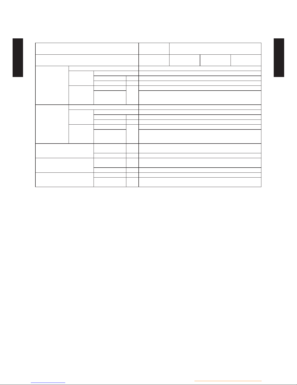
ELECTRICAL SPECIFICATIONS2-22
COMFORT SERIES
Model name (Hydraulic unit)
WGYA050DG6
WGHA050DG
WGYA100DG6
WGHA100DG
Model name (Outdoor unit)
WOYA060LFCA
WOHA060LFCA
WOYA060LFCA
WOHA060LFCA
WOYA080LFCA
WOHA080 LFCA
WOYA100LFTA
WOHA100LFTA
Electrical heater*
(backup-heater)
Type Copper 9W / cm
2
Power supply
Phase 1
Frequency Hz 50
Voltage V 230
Current
Running current
A
26.1
Max. operating
current
(Hydraulic unit)
28.2 A + 10%
Electrical heater
(DHW heater)
Type Copper 8.5W / cm
2
Power supply
Phase 1
Frequency Hz 50
Voltage V 230
Current
Running current
A
6.5
Max. operating
current
(Hydraulic unit)
7.0 A + 10%
Wiring specication*
(For back-up heater power supply)
Main fuse (circuit
breaker) current
A 32
Connection cable mm² 6.0 x 3
Wiring specication
(For DHW heater power supply)
Main fuse (circuit
breaker) current
A 16
Connection cable mm² 1.5 x 3
Wiring specication
(Hydraulic unit to Outdoor unit)
Connection cable mm² 1.5 x 4
Limited wiring
length
m Not available
*: WGY model only.

- (HU01 - 06) -
Hydraulic unit / Split DHW integrated
HYDRAULIC UNIT
WG
050-160DG
HYDRAULIC UNIT
WG
050-160DG
HIGH POWER SERIES
Model name (Hydraulic unit)
WGYG140DG6
WGHG140DG
WGYK160DG9
WGHG140DG
Model name (Outdoor unit)
WOYG112LCTA
WOHG112LCTA
WOYG140LCTA
WOHG140LCTA
WOYK112LCTA
WOHK112LCTA
WOYK140LCTA
WOHK140LCTA
WOYK160LCTA
WOHK160LCTA
Electrical heater*
(backup-heater)
Type Copper 9W / cm
2
Power
supply
Phase 1 3
Frequency Hz 50
Voltage V 230 400
Current
Running current
A
26.1 7.9
Max. operating
current
(Hydraulic unit)
28.2 A + 10% 10 A + 10%
Electrical heater
(DHW heater)
Type Copper 8.5W / cm
2
Power
supply
Phase 1
Frequency Hz 50
Voltage V 230
Current
Running current
A
6.5
Max. operating
current
(Hydraulic unit)
7.0 A + 10%
Wiring specication*
(For back-up heater power
supply)
Main fuse (circuit
breaker) current
A 32 20
Connection cable mm² 6.0 x 3 2.5 x 4
Wiring specication
(For DHW heater power supply)
Main fuse (circuit
breaker) current
A 16
Connection cable mm² 1.5 x 3
Wiring specication
(Hydraulic unit to Outdoor unit)
Connection cable mm² 1.5 x 4
Limited wiring
length
m Not available
*: WGY model only.

- (HU01 - 07) -
Hydraulic unit / Split DHW integrated
HYDRAULIC UNIT
WG
050-160DG
HYDRAULIC UNIT
WG
050-160DG
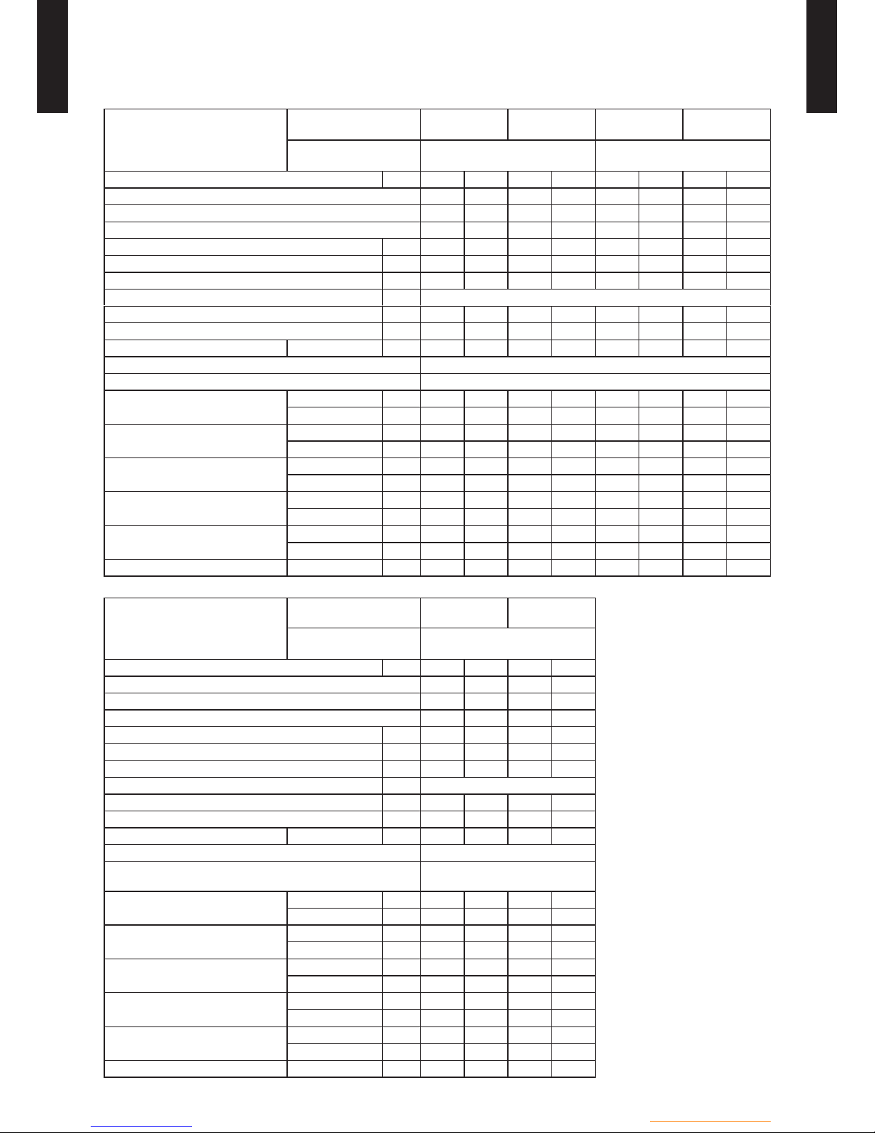
ENERGY EFFICIENCY VALUE
Model name
Hydraulic unit
WGYA050DG6
WGHA050DG
WGYA100DG6
WGHA100DG
Outdoor unit
WOYA060LFCA
WOHA060LFCA
WOYA060LFCA
WOHA060LFCA
WOYA080LFCA
WOHA080 LFCA
WOYA100LFTA
WOHA100LFTA
Heating appilcation °C 55 35 55 35 55 35 55 35
Seaso nal space heating
energy efficiency of heat
pump
%
115 169 115 169 118 156 113 155
Model name
Hydraulic unit
WGYG140DG6
WGHG140DG
Outdoor unit
WOYG112LCTA
WOHG112LCTA
WOYG140LCTA
WOHG140LCTA
Heating appilcation °C 55 35 55 35
Seaso nal space heating
energy efficiency of heat
pump
%
109 151 113 148
Model name
Hydraulic unit
WGYK160DG9
WGHG140DG
Outdoor unit
WOYK112LCTA
WOHK112LCTA
WOYK140LCTA
WOHK140LCTA
WOYK160LCTA
WOHK160LCTA
Heating appilcation °C 55 35 55 35 55 35
Seaso nal space heating
energy efficiency of heat
pump
%
112 154 117 150 117 149
CLASS OF TEMPERATURE CONTROLLER
Controller class
II VI*
Contribution to energy efciency
%
2 4
*Controller class VI : UTW-C55XA, UTW-C58XD, UTW-C74TXF, UTW-C74HXF, UTW-C78XD
- (HU01 - 08) -
Hydraulic unit / Split DHW integrated
HYDRAULIC UNIT
WG
050-160DG
HYDRAULIC UNIT
WG
050-160DG
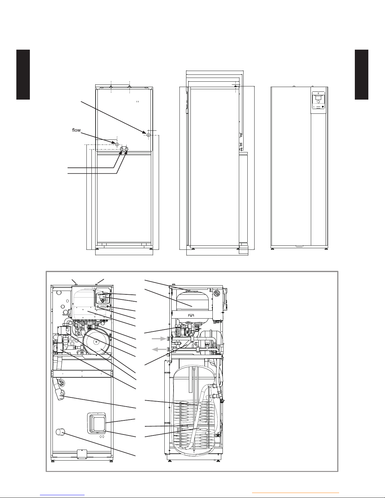
DIMENSIONS32
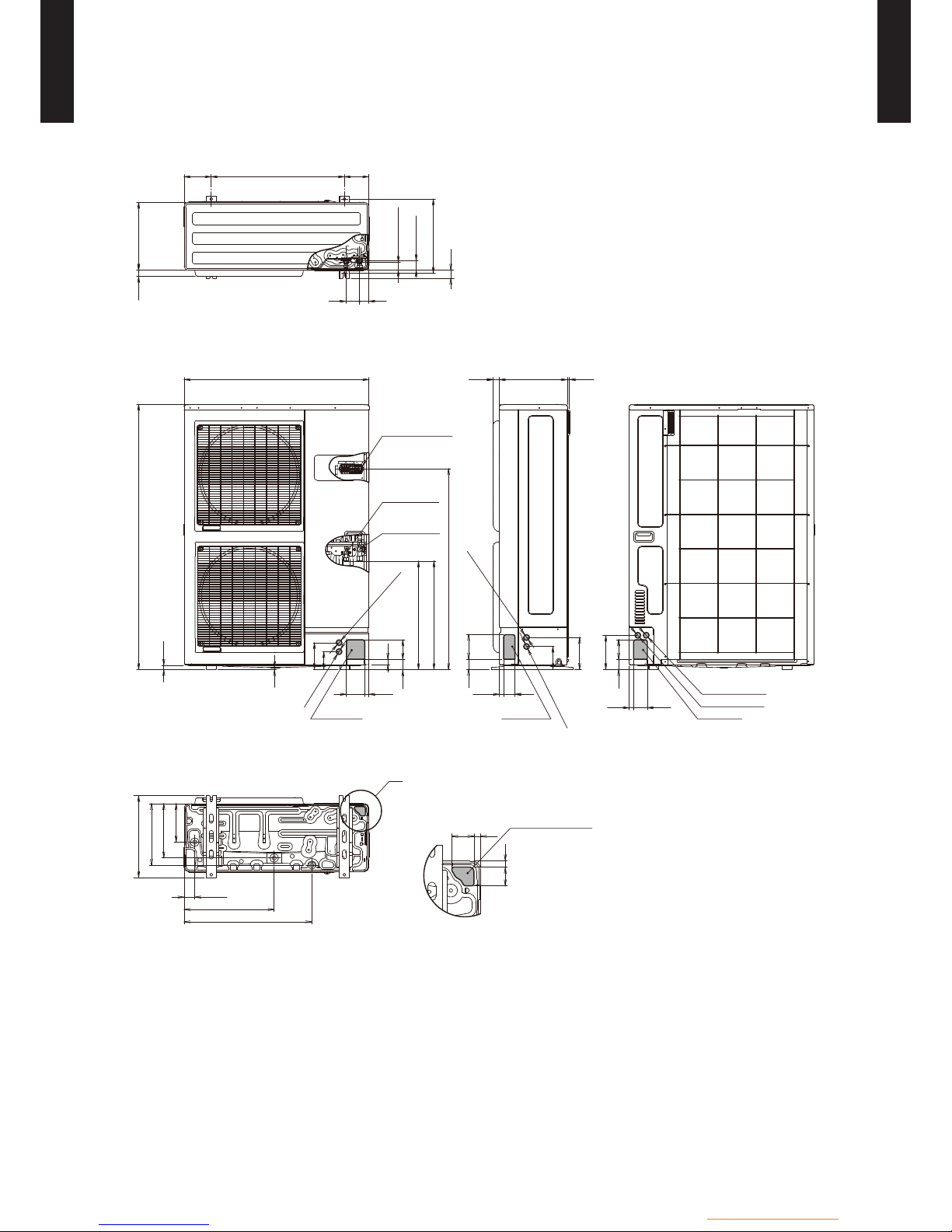
DIMENSIONAL DRAWING3-12
MODEL : WGA050DG, WGA100DG,
WG
G140DG, WGYK160DG9
175 210
47
1296
648
55
1135
1189
244
43
630
599
576
644
1850
1840
698
103
Back view
Heating
DHW
DCW
Heating return
Side view Front view
(Unit : mm)
Legend :
1 - Electric box.
2 - Regulator / User interface.
3 - Start/stop switch.
4 - Hydraulic pumping unit.
5 - Distribution valve.
6 - Gas refrigeration connection.
7 - Liquid refrigeration connection.
8 - Condensation sensor.
9 - Drain valve.
10 - Safety valve.
11 - Safety thermostat.
12 - Manometer.
13 - Manual drainer.
14 - Expansion vessel.
15 - Condenser.
16 - Electrical back-ups DHW (Soapstone).
17 - ACI.
18 - ACI card.
Sensors :
22 - DHW sensor.
21 - Water flow sensor.
23 - Water return sensor.
3
12
1
10
4
9
8
21
23
14
5
17
22
16
11
9
9
2
18
15
13
6 7
- (HU01 - 09) -
Hydraulic unit / Split DHW integrated
HYDRAULIC UNIT
WG
050-160DG
HYDRAULIC UNIT
WG
050-160DG
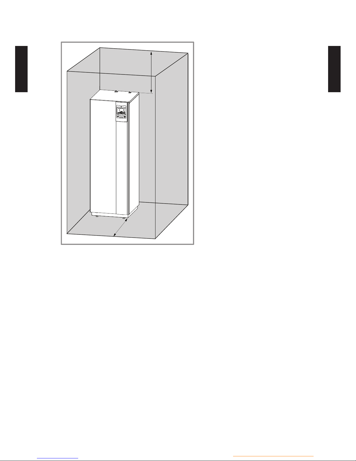
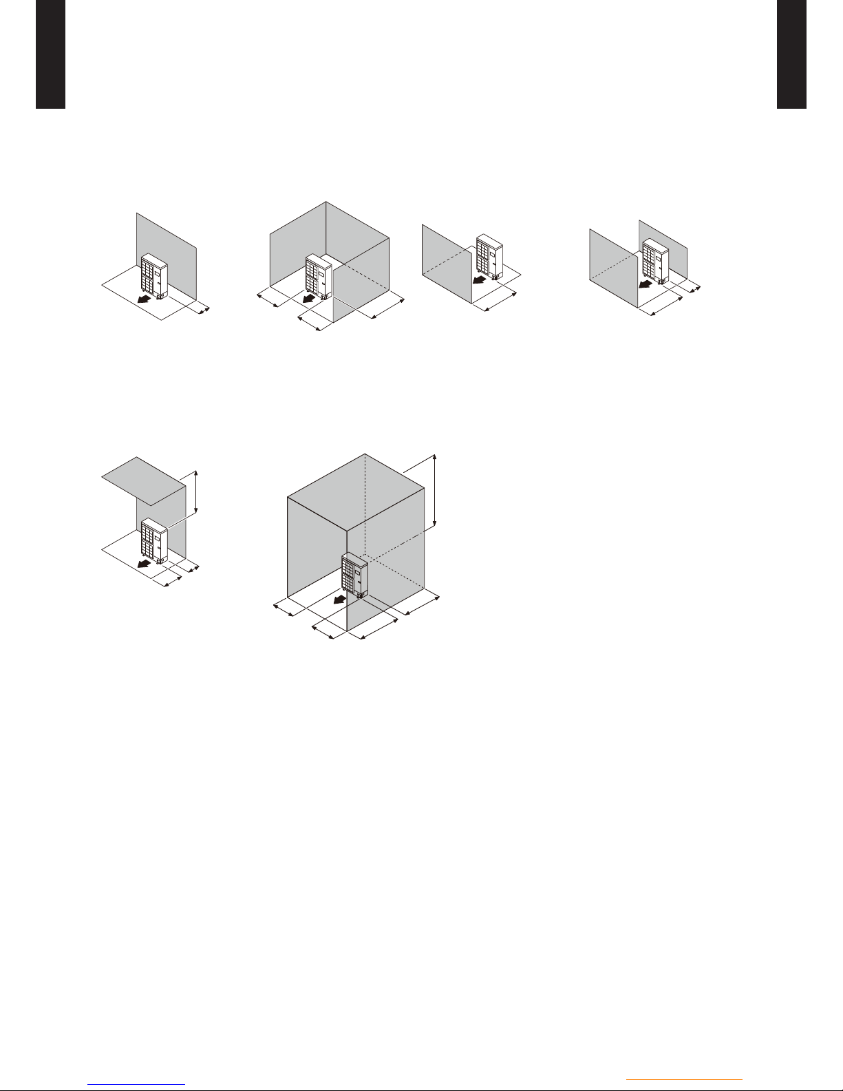
INSTALLATION PLACE3-22
INSTALLATION PRECAUTIONS
The room in which the appliance operates must comply with the prevailing regulations. •
To facilitate maintenance and to allow access to the various components, we recommend that
•
you provide sufcient space all around the hydraulic module.
Be careful not to bring inammable gas near to the heat pump during its installation, in particular
•
when it requires brazing. The appliances are not reproof and should not therefore be installed in
a potentially explosive atmosphere.
To avoid condensation inside the condenser, remove the refrigerant circuit caps only when
building the refrigerant connections.
If the refrigerant connection only occurs at the end of the installation, be sure that the refrigerant
circuit caps* remain in place and tight throughout the installation duration.
*: hydraulic unit side and outdoor unit side
After every intervention on the refrigeration circuit and before nal connection, take care to
replace the plugs in order to avoid any pollution from the refrigeration circuit (The sealing with
tape is prohibited).
300 mm
1000 mm
- (HU01 - 10) -
Hydraulic unit / Split DHW integrated
HYDRAULIC UNIT
WG
050-160DG
HYDRAULIC UNIT
WG
050-160DG
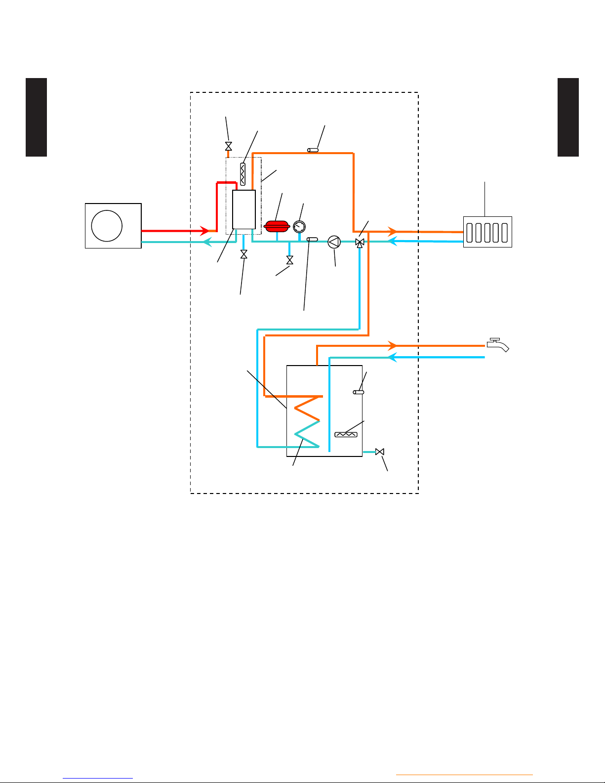
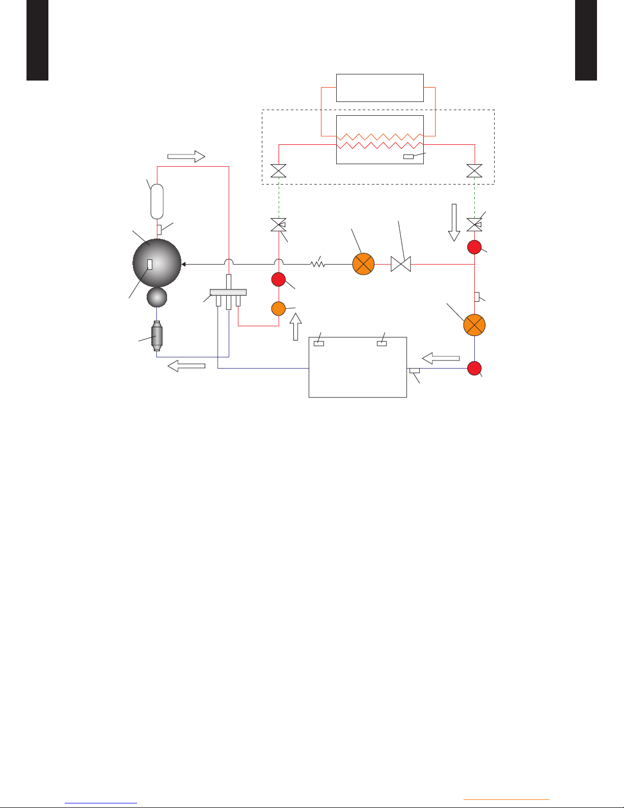
PIPING DIAGRAM42
MODEL : WGA050DG, WGA100DG,
WG
G140DG, WGYK160DG9
Outdoor unit
Refrigerant
Heating terminal
(Floor heating,
Radiator, etc.)
Hot water
Water flow temp. sensor
Air venting valve
Buffer tank
Auxiliary heater *
Pressure
safety valve
Expansion tank
Water heat
exchanger
Supply/drain port
Circulation
pump
Pressure
gauge
Water return temp. sensor
Distribution
valve
Water heat
exchanger
DHW tank
Drain port
DHW backup
heater
Hot water
Cold water
supply
DHW tank
temp.sensor
*: WGY model only
- (HU01 - 11) -
Hydraulic unit / Split DHW integrated
HYDRAULIC UNIT
WG
050-160DG
HYDRAULIC UNIT
WG
050-160DG
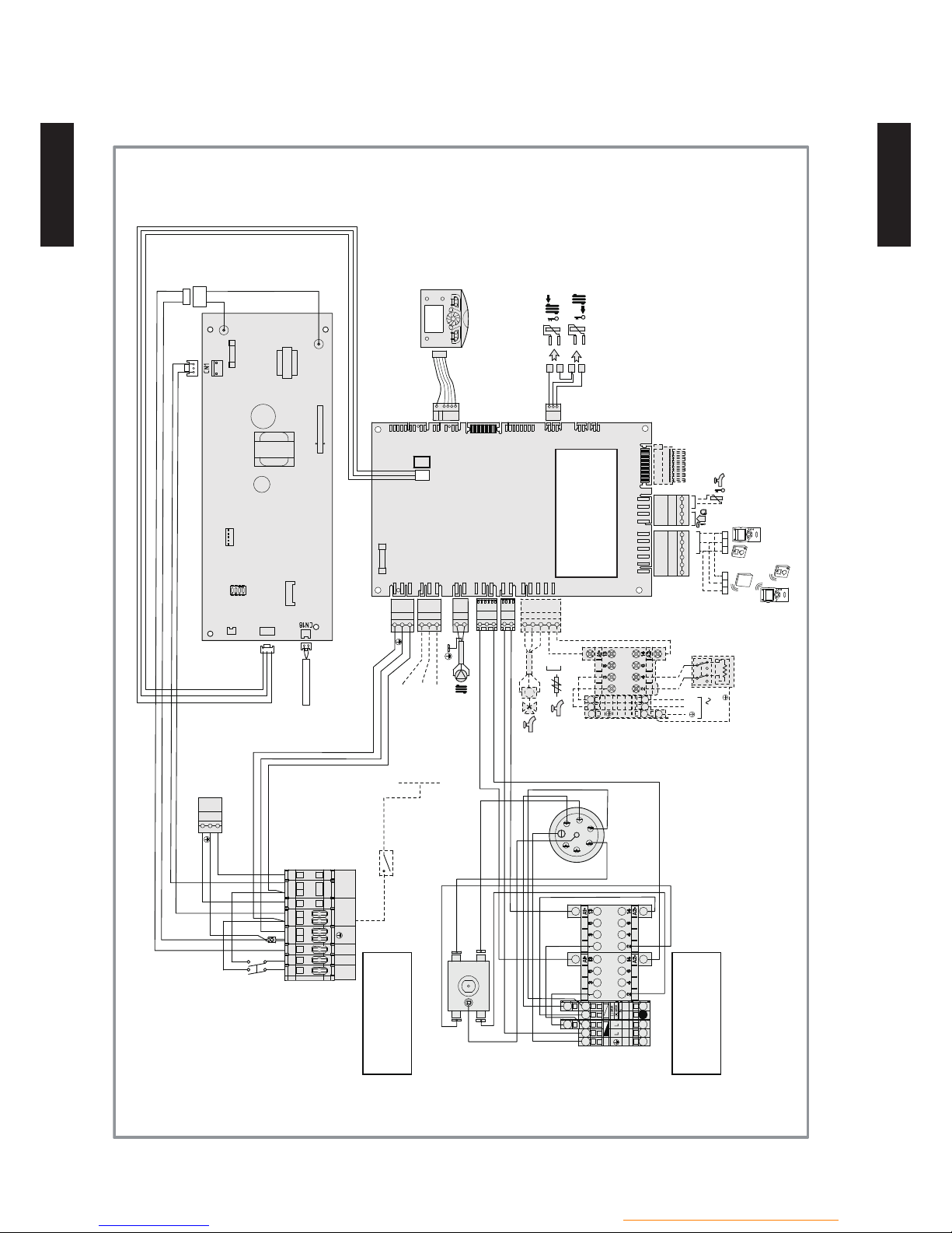
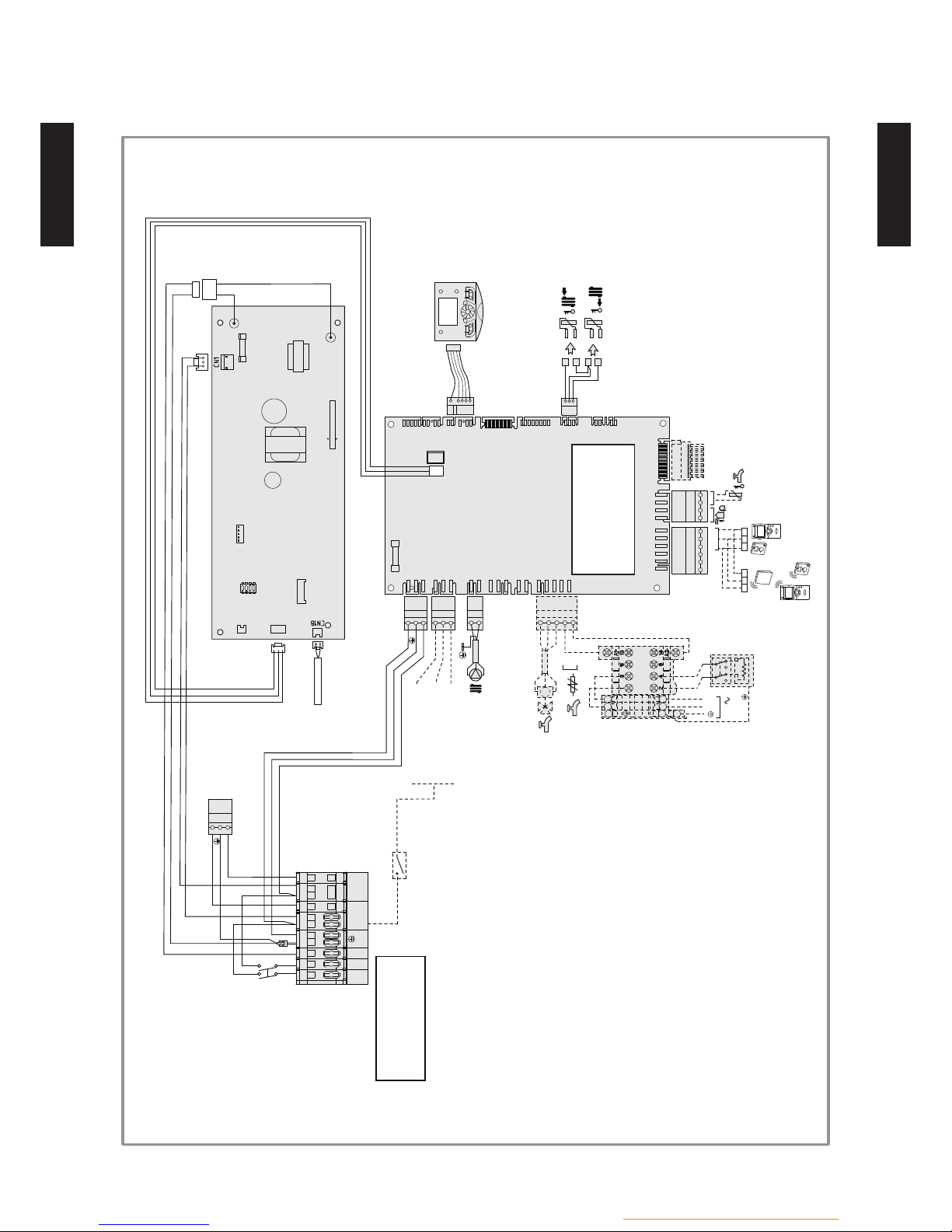
WIRING DIAGRAM52
WIRING DIAGRAM5-12
MODEL : WGYA050DG6, WGYA100DG6, WGYG140DG6
Ou/
Or
Ou/
Or
3 2 1
3 2 1
C.C
2a
1a
1b
2b
EX1
EX2
EX3
L
N
1
2
3
4
5
L
N
COM
L
L
N
X10
X11
X12
X13
X14
X15
X30
X50
X70
X75
X80
X82
X83
X84
X86
X100
X60
3
2
1
M
BK
BN
BU
RP ECS
L
N
L
N
230V
CN21
FUSE 250V/3.15A
FUSE 250V/6.3A
Connections to the heat
pump regulator
(accessories and options)
Power shedding or EJP
Tariffs, day / night
External fault
Return
sensor
Initial
sensor
Start/stop
switch
RP1
RP2
RD1
RD2
BU2
BU1
WH1
WH2
A1 A2
B1 B2
Connection to
terminal block
Connection to
terminal block
Safety
thermostat
Electrical
Back-up
Resistance
Condensation
sensor
- (HU01 - 12) -
Hydraulic unit / Split DHW integrated
HYDRAULIC UNIT
WG
050-160DG
HYDRAULIC UNIT
WG
050-160DG
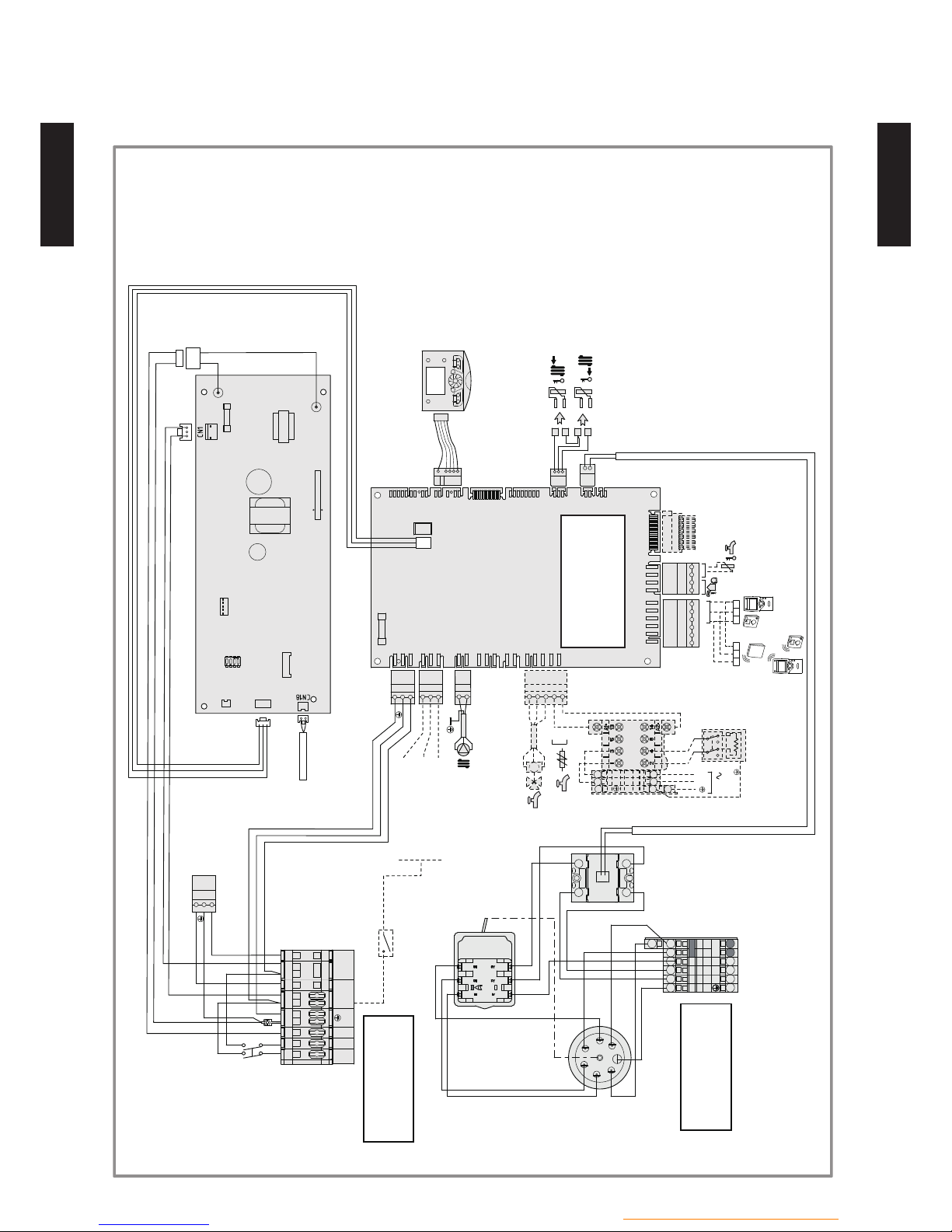
MODEL : WGHA050DG, WGHA100DG, WGHG140DG
Ou/
Or
Ou/
Or
3 2 1
3 2 1
C.C
2a
1a
1b
2b
EX1
EX2
EX3
L
N
1
2
3
4
5
L
N
COM
L
L
N
X10
X11
X12
X13
X14
X15
X30
X50
X70
X75
X80
X82
X83
X84
X86
X100
X60
3
2
1
M
BK
BN
BU
RP ECS
L
N
L
N
230V
CN21
FUSE 250V/3.15A
FUSE 250V/6.3A
Connections to the heat
pump regulator
(accessories and options)
Power shedding or EJP
Tariffs, day / night
External fault
Return
sensor
Initial
sensor
Start/stop
switch
Connection to
terminal block
Condensation
sensor
- (HU01 - 13) -
Hydraulic unit / Split DHW integrated
HYDRAULIC UNIT
WG
050-160DG
HYDRAULIC UNIT
WG
050-160DG
MODEL : WGYK160DG9
Ou/
Or
Ou/
Or
3 2 1
3 2 1
C.C
2a
1a
1b
2b
EX1
EX2
EX3
L
N
1
2
3
4
5
L
N
COM
L
L
N
X10
X11
X12
X13
X14
X15
X30
X50
X70
X75
X80
X82
X83
X84
X86
X100
X60
3
2
1
M
BK
BN
BU
RP ECS
L
N
L
N
230V
CN21
FUSE 250V/3.15A
FUSE 250V/6.3A
Connections to the heat
pump regulator
(accessories and options)
RD1
RD2
BU2
BU1
BK1
BK2
CAPILLAIRE
GN/YE
1 2 3 4 5 6
L1 L2 L3
COMMUN
1/L1
2/T1
3/L2
4/T2
WH
BN
RD
BK
BU
BU
WH
Connection to
terminal block
Electrical
Back-up
Resistance
Safety
thermostat
Solid state
relay
Power shedding or EJP
Tariffs, day / night
External fault
Connection to
terminal block
External component
contact
sensor
Initial
sensor
Start/stop
switch
- (HU01 - 14) -
Hydraulic unit / Split DHW integrated
HYDRAULIC UNIT
WG
050-160DG
HYDRAULIC UNIT
WG
050-160DG
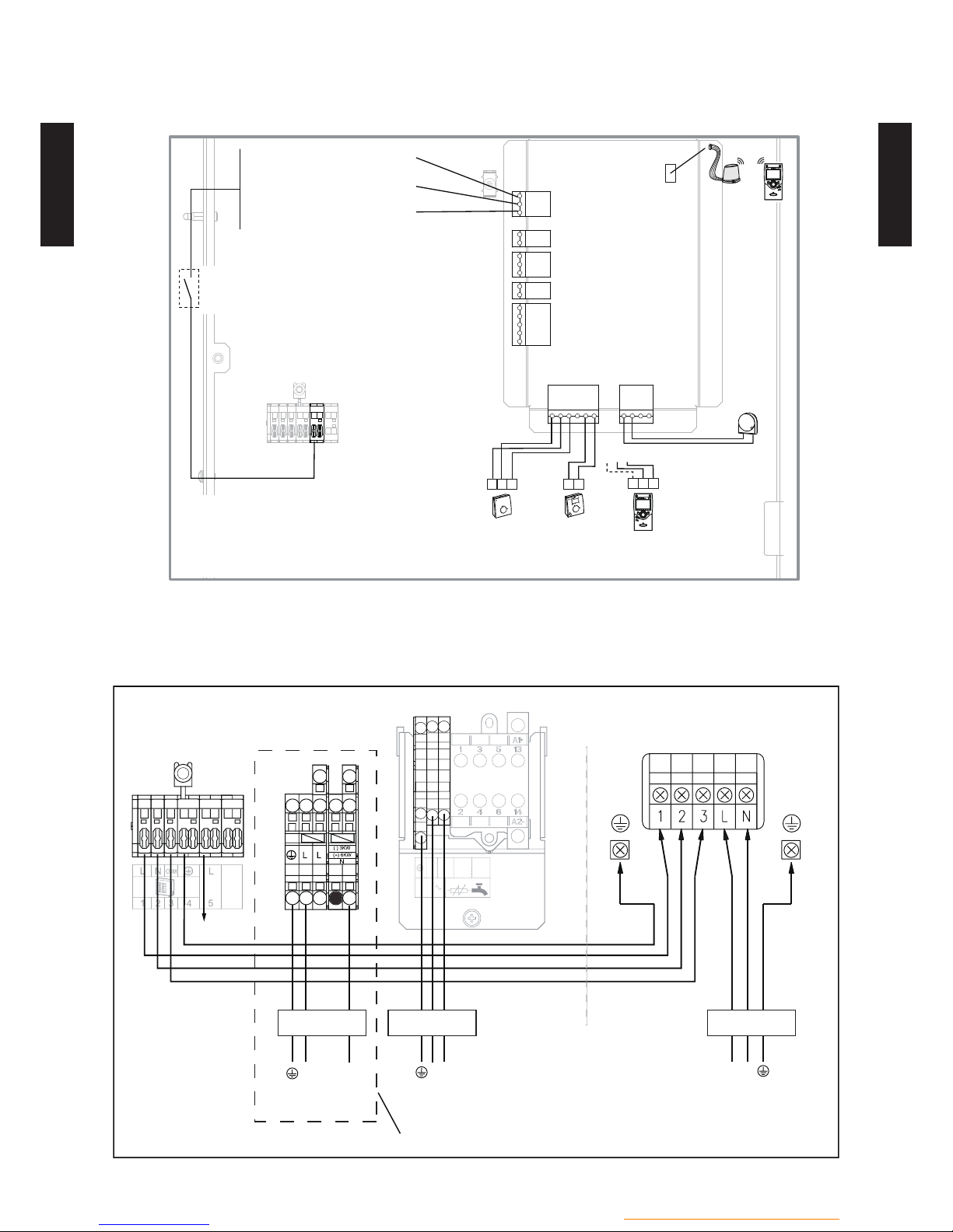
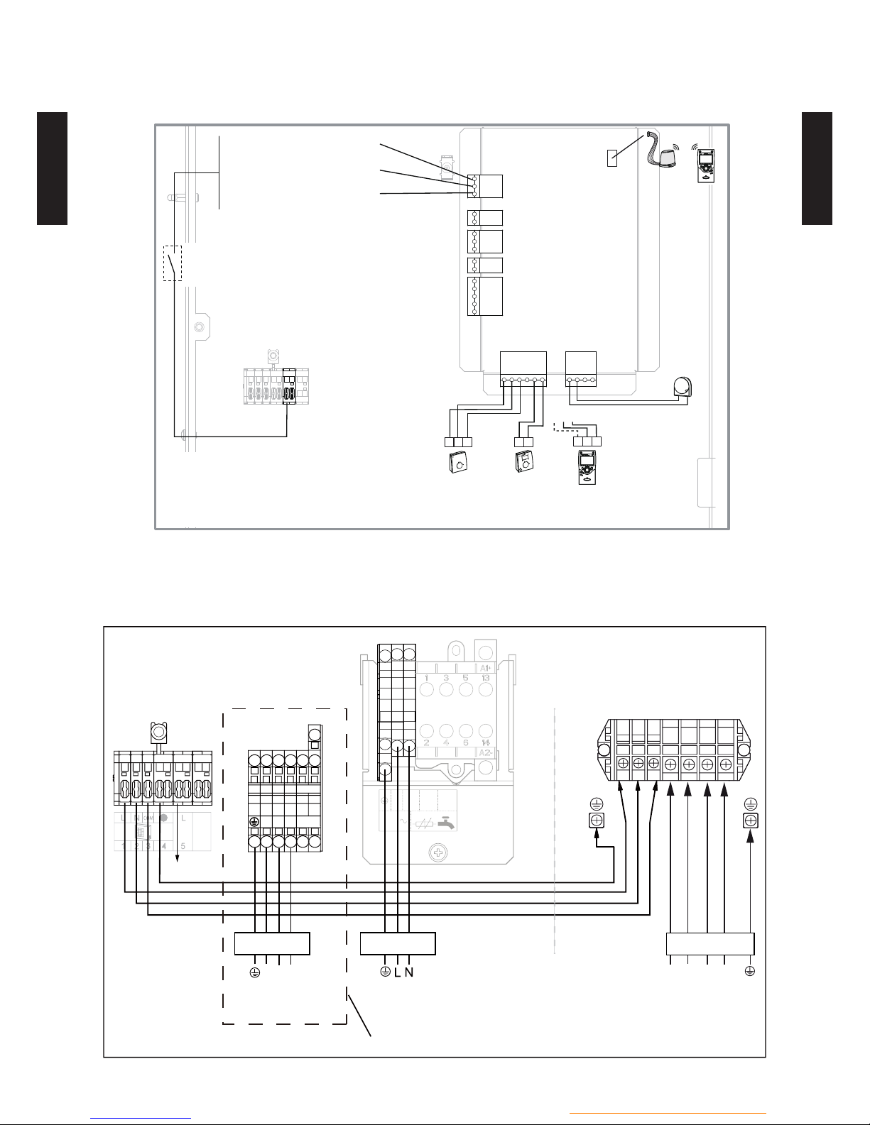
EXTERNAL CONNECTION DIAGRAM5-22
MODEL : WGA050DG, WGA100DG, WGG140DG
EX1
EX2
EX3
X60
X86
L
X84
X11
2
1
3
M B9
B2 M B1 3 2 1
1
2
1
3 2
B2M
B1
Outdoor
sensor
Room
thermostat**
Room
thermostat**
Remote
control**
Wireless
remote
control**
Power shedding or EJP
(peak day removal)
Tariffs, peak times/off-peak
times, day / night
External fault
External component
contact*
(faults, load
shedder, power meter)
oror
* If the control device does not provide a potential-free contact, the contact must be relayed to create equivalent wiring.
In all cases, please refer to the instruction manuals for the external components (load shedder, power meters) to create
the wiring.
** Option The connection of terminal 3 of the remote control is not mandatory. (lighting of the room control unit)
Regulation of wire size and circuit breaker differs from each locality, please refer in accordance with the regional standard.
1 2 3
4
5
6
L N
L N
Outdoor unit single phase
Hydraulic unit
Electricity supply
230 V single phase
Electrical back-up
supply 230 V
single phase
External component
contact *
Red
Blue
Brown
Green / yellow
Interconnection
between the outdoor unit
and the hydraulic unit
Circuit breaker 1
Circuit breaker 2
230 V
L
N
L N
2
4
L
N
DHW Electricity
supply 230 V
Circuit breaker 3
WSY model only
- (HU01 - 15) -
Hydraulic unit / Split DHW integrated
HYDRAULIC UNIT
WG
050-160DG
HYDRAULIC UNIT
WG
050-160DG
MODEL : WGYK160DG9
EX1
EX2
EX3
X60
X86
L
X84
X11
2
1
3
M B9
B2 M B1 3 2 1
1
2
1
3 2
B2M
B1
Outdoor
sensor
Room
thermostat**
Room
thermostat**
Wireless
remote
control**
Remote
control**
Power shedding or EJP
(peak day removal)
Tariffs,
peak times/off-peak
times, day / night
External fault
External component
contact*
(faults, load
shedder, power meter)
oror
* If the control device does not provide a potential-free contact, the contact must be relayed to create equivalent wiring.
In all cases, please refer to the instruction manuals for the external components (load shedder, power meters) to create
the wiring.
** Option The connection of terminal 3 of the remote control is not mandatory. (lighting of the room control unit)
Regulation of wire size and circuit breaker differs from each locality, please refer in accordance with the regional standard.
230 V
L
N
L N
2
4
1 2 3
4
5
6
1 2 3 L1
L2 L3 N
1 2 3 4 5 6
L1 L2 L3
COMMUN
Outdoor unit 3-phaseHydraulic unit
L1
L2
L3
N
Electricity supply
400 V 3-phase
L1L2L3
Electrical back-up
supply 400 V
3-phase
DHW Electricity
supply 230 V
Circuit breaker 1 Circuit breaker 3
Circuit breaker 2
External component
contact *
Red
Blue
Brown
Green / yellow
Interconnection
between the outdoor unit
and the hydraulic unit
WSY model only
- (HU01 - 16) -
Hydraulic unit / Split DHW integrated
HYDRAULIC UNIT
WG
050-160DG
HYDRAULIC UNIT
WG
050-160DG
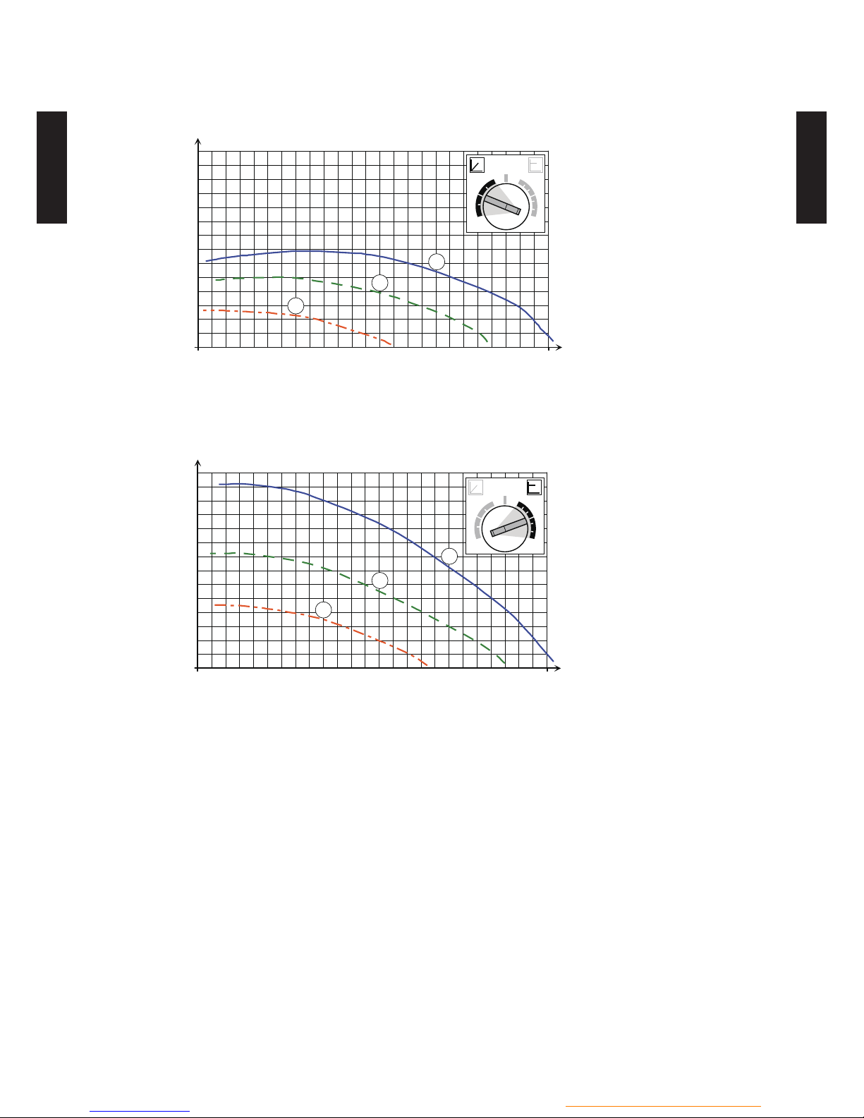
HYDRAULIC PERFORMANCE62
STATIC PRESSURE DROP UNIT6-12
VARIABLE PRESSURE
1mbar = 10 mmCE = 100 Pa
0
100
200
300
400
500
600
mbar
m /h
3
1
1.5 2 2.50.50
2
4
66
ext. in
2
4
6 7
4
2
CONSTANT PRESSURE
1mbar = 10 mmCE = 100 Pa
0
100
200
300
400
500
600
mbar
m /h
3
1
1.5 2 2.50.50
2
4
77
ext. in
2
4
6 7
4
2

- (HU01 - 17) -
Hydraulic unit / Split DHW integrated
HYDRAULIC UNIT
WG
050-160DG
HYDRAULIC UNIT
WG
050-160DG
SAFETY DEVICES72
Protection form
Model
WGA050DGWGA100DGWGG140DGWGYK160DG9
Circuit protection Current fuse (Main PCB) 20 A
High pressure protection Safety valve Activate (at 3 bar or more): Safty valve open
- (HU01 - 18) -
Hydraulic unit / Split DHW integrated
HYDRAULIC UNIT
WG
050-160DG
HYDRAULIC UNIT
WG
050-160DG
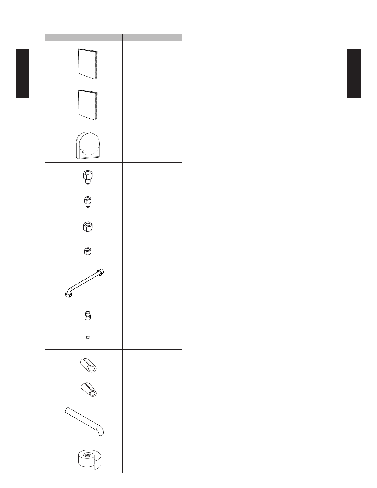
STANDARD ACCESSORIES82
Name and shape Q'ty Application
Installation and operating
manual
1
Operation manual
5
Outdoor sensor
1
To monitor the outdoor
temperature.
Adaptor(Large)
1
To connect the ared
connection and the
hydraulic unit.
(Only for comfort series)
Adaptor(Small)
1
Nut(Large)
1
To connect the ared
connection and the
hydraulic unit.
(Only for comfort series)
Nut(Small)
1
DHW hose
2
To connect the Hydraulic
unit.
Dielectric connection
2
To connect the Hydraulic
unit.
Gascket
4
To connect the Hydraulic
unit.
Insulation right
2
To isolate the
connections and tubes.
Insulation conical
2
Insulation tube
2
Insulation tape
1

1. OUTDOOR UNIT
DTW_3SP003E_01--CHAPTER01
2016.02.18
3 PHASE TYPE :
WOK112LCTA
WOK140LCTA
WOK160LCTA

CONTENTS
OUTDOOR 11 UNIT
11 FEATURES
11111111111111111111111111111111111111111111111111111111111111111111111111111111111111111111111111111111111111111
OU01 - 01
21 SPECIFICATIONS
1111111111111111111111111111111111111111111111111111111111111111111111111111111111111111111111111
OU01 - 04
2-11 NOMINAL CAPACITY AND NOMINAL INPUT
1111111111111111111111111111111111111111111111111111
OU01 - 04
2-21 TECHNICAL SPECIFICATIONS
1111111111111111111111111111111111111111111111111111111111111111111111111111
OU01 - 05
2-31 PRODUCT FICHE
1111111111111111111111111111111111111111111111111111111111111111111111111111111111111111111111111111
OU01 - 06
2-41 PRODUCT INFORMATION
1111111111111111111111111111111111111111111111111111111111111111111111111111111111111
OU01 - 07
2-51 ELECTRICAL SPECIFICATIONS
11111111111111111111111111111111111111111111111111111111111111111111111111
OU01 - 10
31 DIMENSIONS
111111111111111111111111111111111111111111111111111111111111111111111111111111111111111111111111111111111111
OU01 - 11
3-11 DIMENSIONAL DRAWING
1111111111111111111111111111111111111111111111111111111111111111111111111111111111111
OU01 - 11
3-21 INSTALLATION PLACE
111111111111111111111111111111111111111111111111111111111111111111111111111111111111111111
OU01 - 12
41 PIPING DIAGRAM
1111111111111111111111111111111111111111111111111111111111111111111111111111111111111111111111111
OU01 - 14
51 WIRING DIAGRAM
11111111111111111111111111111111111111111111111111111111111111111111111111111111111111111111111
OU01 - 15
5-11 WIRING DIAGRAM
11111111111111111111111111111111111111111111111111111111111111111111111111111111111111111111111111
OU01 - 15
5-21 EXTERNAL INPUT & OUTPUT
11111111111111111111111111111111111111111111111111111111111111111111111111111
OU01 - 16
61 CAPACITY TABLES
11111111111111111111111111111111111111111111111111111111111111111111111111111111111111111111
OU01 - 19
6-11 HEATING CAPACITY
1111111111111111111111111111111111111111111111111111111111111111111111111111111111111111111111
OU01 - 19
6-21 COOLING CAPACITY
111111111111111111111111111111111111111111111111111111111111111111111111111111111111111111111
OU01 - 22
71 OPERATION NOISE
11111111111111111111111111111111111111111111111111111111111111111111111111111111111111111111
OU01 - 25
7-11 NOISE LEVEL CURVE
11111111111111111111111111111111111111111111111111111111111111111111111111111111111111111111
OU01 - 25
7-21 SOUND LEVEL CHECK POINT
11111111111111111111111111111111111111111111111111111111111111111111111111111
OU01 - 26
81 OPERATION RANGE
11111111111111111111111111111111111111111111111111111111111111111111111111111111111111111
OU01 - 27
91 SAFETY DEVICES
111111111111111111111111111111111111111111111111111111111111111111111111111111111111111111111111
OU01 - 28
101 STANDARD ACCESSORIES
111111111111111111111111111111111111111111111111111111111111111111111111
OU01 - 29
- (OU01 - 01) -
Outdoor unit / 3 phase
OUTDOOR UNIT
WO
K112-160LCTA
OUTDOOR UNIT
WO
K112-160LCTA
FEATURES11
MODELS :
WO
K112LCTA, WOK140LCTA, WOK160LCTA
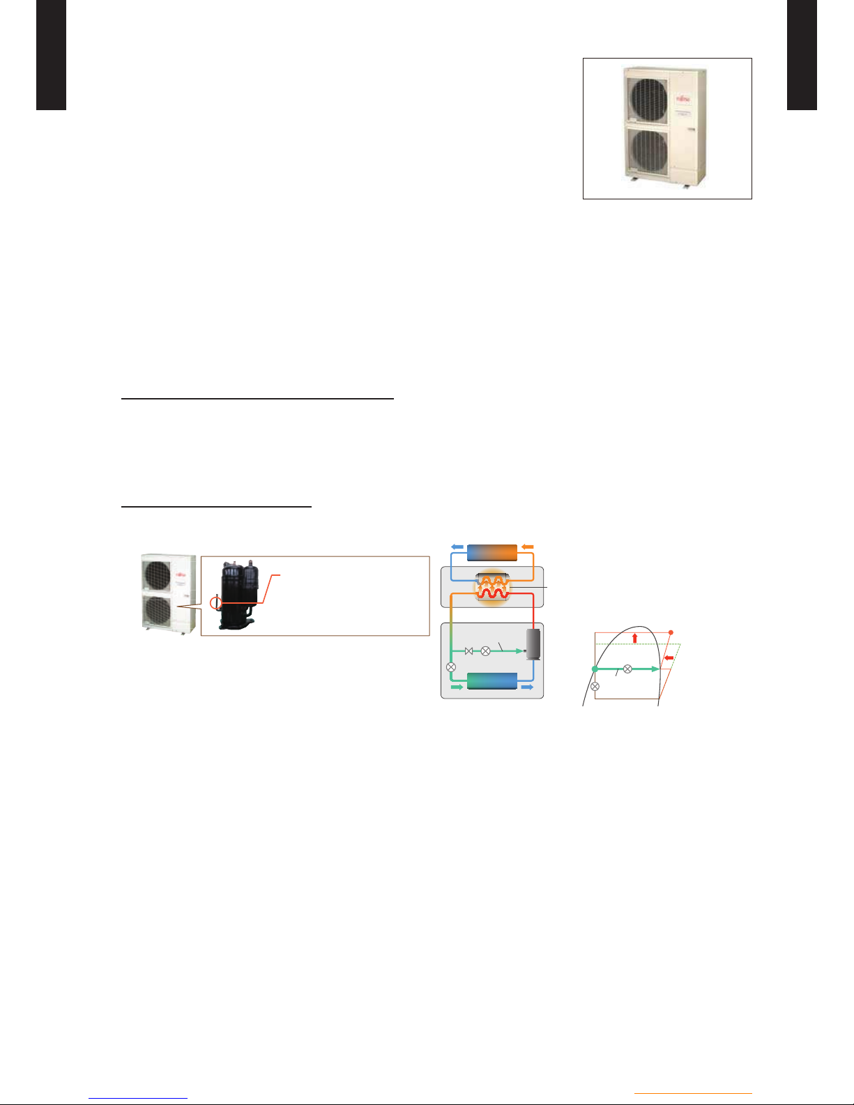
HIGH PERFORMANCE
Powerful heating
z
High power models realize high leaving water temperature and high heating capacity even at
low ambient temperature by newly developed "Linear Control Injection Technology".
It is possible to provide high water temperature and warm rooms immediately in cold region
during winter.
High leaving water temperature
High leaving water temperature 60°C kept down to -20°C outdoor temperature without using
backup heater.
High heating capacity
FUJITSU GENERAL’s advanced
Linear Control Injection Technology
Twin Rotary Compressor
with Linear Control Injection port
Injection port
Linear Control
Injection
Evaporator
Heati n g c yc l e
Water
Heat
exchanger
Outdoor unit
Indoo r u n i t
Linear Control
Injection
Normal
refrigerant
circuit
High compression
It realizes the high condensing temperature
without overheating discharge gas
temperature by Linear Control Injection
process during compression.
Therefore, the condensing temperature
rises up higher than normal circuit.
A higher hot water temperature is realized
by controling the injection amount
according to the usage state.

- (OU01 - 02) -
Outdoor unit / 3 phase
OUTDOOR UNIT
WO
K112-160LCTA
OUTDOOR UNIT
WO
K112-160LCTA
High efciency
z
Energy efciency is improved by the Linear Control Injection Technology and the optimization
of refrigerant cycle control. High power model realizes high performance and high efciency by
adopting twin sensors and control technology corresponding to hot water heating.
High COP
11 kW
4.30
14 kW
4.22
16 kW
A7W35 condition
4.10
Proportion of primary energy into heating
energy of 100%
Direct electrical heating
278%
117%
109%
79%
Prima ry Energy Co n s u m p t i o n*
*Elect r i c i ty loss is d ifferen t du e t o p ow er p l a nt . Effic ie n c y of p o we r p la n t : 3 6 %
Oil heating
Gas condensing boiler
100%
Energy
heating
Optimization of refrigerant cycle operation
Outdo o r u n i t
Hydraulic indoor unit
Emitter system
Refrigerant
Hot wat e r
Temperature
sensor
Pressure sensor
Co-axial H e a t Exchan g e r
Accurate temperature control by DC inverter
technology
V-PAM inverter
technology
Time
High
Temperature
Constant
Wide operation range
z
Improvement operation range depending
on the optimization of refrigerant cycle
control
35°C
-25°C
0°C
Outdoor temperature
Others
z
2 stage Low noise mode* •
Peak cut function* •
*Optional parts are required.
- (OU01 - 03) -
Outdoor unit / 3 phase
OUTDOOR UNIT
WO
K112-160LCTA
OUTDOOR UNIT
WO
K112-160LCTA
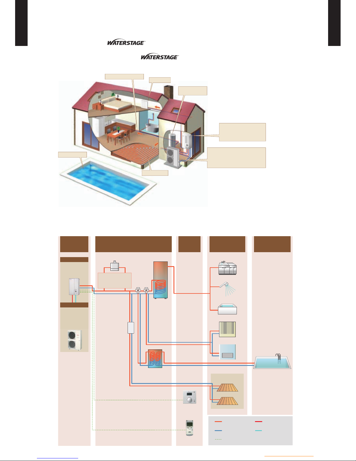
WIDE COMFORT
Wide comfort by
The clean energy produced by reliably delivers “comfort” to diverse spaces in
the home up to the living room, bedrooms, bath and swimming pool.
Radiator
Domestic hot water
Swimming pool
Floor heating
Domestic hot
water tank
Hot water supply
Indoor unit
Take thermal energy
from atmosphere
Outdoor unit
System conguration
z
Basic Unit
Controller
(Option)
Heat i ng & H o t Water
(Field Supplied)
Hot Wat e r
(Outdoor)
System Components
(Options)
Boiler ( Field Supplied) DHW Tank
Swimming Pool
2nd circ u i t k i t
Heat Exchanger
UTW-ESPXA
& Swimm i ng P o o l K i t
UTW-KSPXD
Floor heating
Remote C o n t r o l
Room The r m o s t a t
Hot wate r
Shower
Bath
Radiator
Fan coil
Contro l c ab l e
Supply ho t wa te r Gas refrigerant
Return wate r Liquid refrigerant
UTW-T30XA
UTW-T30XD
High Powe r m odel
High Powe r m odel
UTW-C75XA
or
UTW-C78XD
UTW-C55XA
or
UTW-C58XD
Outdo o r unit
Indoor unit
WOK112LCTA
WOK140LCTA
WOK160LCTA
WSYK160DG9
WSHK140DG
UTW-KZSXD
UTW-T20XA
Boiler Connection kit
UTW-KBSXD
& Balanc i n g Ves s e l
UTW-TEVXA
- (OU01 - 04) -
Outdoor unit / 3 phase
OUTDOOR UNIT
WO
K112-160LCTA
OUTDOOR UNIT
WO
K112-160LCTA
SPECIFICA TIONS21
NOMINAL CAPACITY AND NOMINAL INPUT2-11
* Test conditions comply with EN14511-2
Model name (Outdoor unit) WOÛK112LCTA WOÛK140LCTA WOÛK160LCTA
POWER SOURCE 3Ø 400V ~ 50Hz
+7°C/+35°C
floor heating
Heating capacity
Minimum
kW
6.20 6.20 6.20
Nominal 10.80 13.50 15.17
Maximum 19.50 21.00 22.00
Input power
Nominal
2.51 3.20 3.70
COP - 4.30 4.22 4.10
+7°C/+45°C
radiators
Heating capacity
Nominal
kW
9.90 12.10 12.75
Input power 2.98 3.78 3.97
COP - 3.32 3. 20 3.21
+2°C/+35°C
floor heating
Heating capacity
Nominal
kW
10.77 13.00 13.50
Input power 3.40 4.15 4.34
COP - 3.17 3.13 3.11

- (OU01 - 05) -
Outdoor unit / 3 phase
OUTDOOR UNIT
WO
K112-160LCTA
OUTDOOR UNIT
WO
K112-160LCTA
TECHNICAL SPECIFICATIONS2-21
Model name (Outdoor unit) WOÛK112LCTA WOÛK140LCTA WOÛK160LCTA
Enclosure
Colour BEIGE (10YR 7.5/1.0)
Material Steel sheet
Dimensions
(H x W x D)
Net
mm
1290 x 900 x 330
Gross 1430 x 1050 x 445
Weight
Net
kg
99
Gross 109
Heat exchanger type
Dimensions (H x W x D)
mm
1260 x 900 x 36.4
Fin pitch 1.3
Rows & Stages 2 x 60
Pipe type C opper
Fin
Type (Material) Corrugate (Aluminium)
Surface treatment Corrosion resistance (Blue n)
Fan
Airow rate Heating m³/h 6200 6900
Type x Q'ty Propeller x 2
Discharge direction Horizontal
Motor Quantity 2
Motor output W 100
Compressor
Type x Q'ty DC 2 rotary (Liquid injection) x 1
Motor output W 3,750
Operation range
Heating
Min
°CDB
-25
Max 35
Sanitary
water
Min -25
Max 35
Refrigerant
Type R410A
Charge g 2, 500
Control Expansion valve (electric type)
Nr of circuits 1
Refrigerant oil
Type VG74
Charged volume l 1.55
Connection pipe
Type
Liquid Flare connection
Gas Flare connection
Size
(Standard)
Liquid
mm
9.52
Gas 15.88
Drain
Type x Q'ty Socket x 3
Size mm Ø2 0
Pre-charge length
m
15
Max. length 20
Min. length 5
Additional refrigerant charge g/m 50
Max. height difference m 15
Defrost method Reverse cycle
Defrost control Outdoor heat exchanger temperature sensor
Capacity control method Inverter control
- (OU01 - 06) -
Outdoor unit / 3 phase
OUTDOOR UNIT
WO
K112-160LCTA
OUTDOOR UNIT
WO
K112-160LCTA
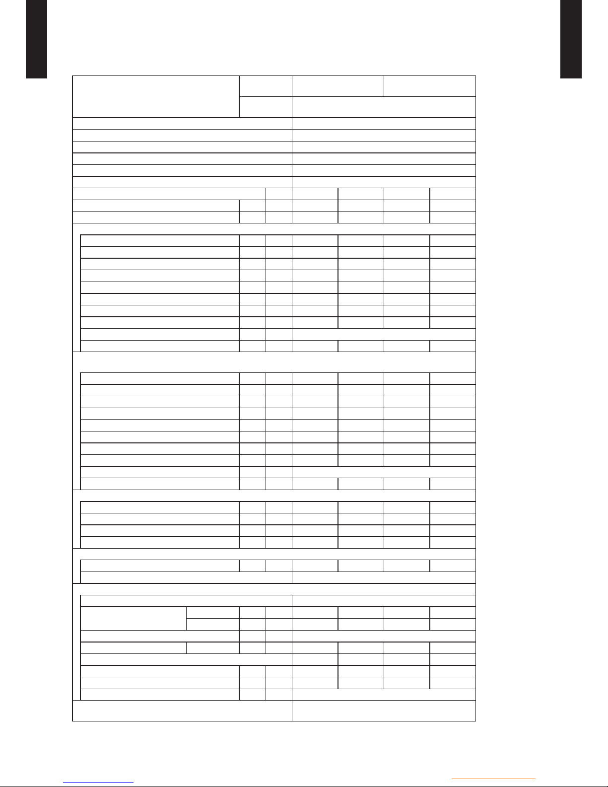
PRODUCT FICHE2-31
Product che according to Commission Delegated Regulation (EU) 811/2013
Model
Hydraulic unit
WSYK160DG9
WSHG140DG *1
WGYK160DG9
WGHG140DG *1
WSYK160DG9
WSHG140DG *1
WGYK160DG9
WGHG140DG *1
Outdoor unit
WOYK112LCTA
WOHK112LCTA
WOYK140LCTA
WOHK140LCTA
Temperature application °C 55
35
55
35
55
35
55
35
Declared load prole — — L L — — L L
Seasonal space heating energy efciency class A+ A++ A+ A++ A+ A++ A+ A++
Water heating energy efciency class — — A A — — A A
Rated heat output kW 9 11 9 11 11 13 11 13
Annual energy consumption kWh 6669 5930 6669 5930 7803 6738 7803 6738
Annual electricity consumption kWh — — 1166 1166 — — 1166 1166
Annual fuel consumption GJ Not applicable
Seasonal space heating energy efciency % 112 154 112 154 117 150 117 150
Water heating energy efciency % — — 88 88 — — 88 88
Sound power level Indoor unit dB 46 46 46 46 46 46 46 46
Work only during off-peak hours
Not applicable
Specic precautions in assembled, installed or maintained Refer to the installation and operating manuals.
Rated heat output
Colder climate kW 12 15 12 15 15 17 15 17
Warmer climate kW 11 14
11 14 14 16 14 16
Annual energy consumption
Colder climate kWh 11554 10911 11554 10911 13692 12567 13692 12567
Warmer climate kWh 4432 3505 4432 3505 5064 4039 5064 4039
Annual electricity consumption
Colder climate kWh — — 1320 1320 — — 1320 1320
Warmer climate kWh — — 1166 1166 — — 1166 1166
Seasonal space heating energy
efciency
Colder climate % 100 124 100 124 100 122 100 122
Warmer climate % 123 194 123 194 133 191 133 191
Water heating energy efciency
Colder climate % — — 79 79 — — 79 79
Warmer climate % — — 88 88 — — 88 88
Sound power level Outdoor unit dB 69 68 69 68 70 68 70 68
Model
Hydraulic unit
WSYK160DG9
WSHG140DG *1
WGYK160DG9
WGHG140DG *1
Outdoor unit
WOYK160LCTA
WOHK160LCTA
Temperature application °C 55
35
55
35
Declared load prole — — L L
Seasonal space heating energy efciency class A+ A+ A+ A+
Water heating energy efciency class — — A A
Rated heat output kW 13 14 13 14
Annual energy consumption kWh 9062 7408 9062 7408
Annual electricity consumption kWh — — 1166 1166
Annual fuel consumption GJ Not applicable
Seasonal space heating energy efciency % 117 149 117 149
Water heating energy efciency % — — 88 88
Sound power level Indoor unit dB 46 46 46 46
Work only during off-peak hours
Not applicable
Specic precautions in assembled, installed or maintained
Refer to the installation and
operating manuals.
Rated heat output
Colder climate kW 17 18 17 18
Warmer climate kW 16 17 16 17
Annual energy consumption
Colder climate kWh 15667 13710 15667 13710
Warmer climate kWh 5522 4300 5522 4300
Annual electricity consumption
Colder climate kWh — — 1320 1320
Warmer climate kWh — — 1166 1166
Seasonal space heating energy
efciency
Colder climate % 100 119 100 119
Warmer climate % 139 192 139 192
Water heating energy efciency
Colder climate % — — 79 79
Warmer climate % — — 88 88
Sound power level Outdoor unit dB 71 71 71 71
*1: Optional electrical back up heater consumption is taken into account in the performance calculation.

- (OU01 - 07) -
Outdoor unit / 3 phase
OUTDOOR UNIT
WO
K112-160LCTA
OUTDOOR UNIT
WO
K112-160LCTA
PRODUCT INFORMATION2-41
Product information according to Commission Delegated Regulation (EU) 813/2013
Product information is based on the average climate condition.
Model
Hydraulic unit
WSYK160DG9
WSHG140DG *1
WGYK160DG9
WGHG140DG *1
WSYK160DG9
WSHG140DG *1
WGYK160DG9
WGHG140DG *1
Outdoor unit
WOYK112LCTA
WOHK112LCTA
WOYK140LCTA
WOHK140LCTA
Air-to-water heat pump Yes
Water-to-water heat pump No
Brine-to-water heat pump No
Low-temperature heat pump No
Equipped with a supplementary heater Yes
Heat pump combination heater Yes
Temperature application °C 55
35
55
35
55
35
55
35
Rated heat output *2
Prated
kW 9 11 9 11 11 13 11 13
Seasonal space heating energy efciency ƞ
s % 112 154 112 154 117 150 117 150
Declared capacity for heating for part load at indoor temperature 20 °C and outdoor temperature T
j
Tj = –7 °C Pdh kW 8.2 10.0 8.2 10.0 10.0 11.1 10.0 11.1
T
j = +2 °C Pdh kW 5.0 6.1 5.0 6.1 6.1 6.7 6.1 6.7
T
j = +7 °C Pdh kW 5.9 6.2 5.9 6.2 5.9 6.2 5.9 6.2
T
j = +12 °C Pdh kW 7.0 7.4 7.0 7.4 7.1 7.3 7.1 7.3
T
j = bivalent temperature Pdh kW 8.2 10.0 8.2 10.0 10.0 11.1 10.0 11.1
T
j = operation limit temperature Pdh kW 8.1 9.9 8.1 9.9 9.3 10.8 9.3 10.8
T
j = –15 °C (if TOL < –20 °C) Pdh kW — — — — — — — —
Bivalent temperature T
biv °C -7 -7 -7 -7 -7 -7 -7 -7
Cycling interval capacity for heating P
cych kW Not applicable
Degradation co-efcient *3 Cdh — 0.9 0.9 0.9 0.9 0.9 0.9 0.9 0.9
Declared coefcient of performance or primary energy ratio for part load at indoor temperature 20 °C and outdoor temperature T
j
Tj = –7 °C
COPd
— 1.91 2.65 1.91 2.65 1.95 2.53 1.95 2.53
T
j = +2 °C
COPd
— 2.74 3.74 2.74 3.74 2.85 3.65 2.85 3.65
T
j = +7 °C
COPd
— 3.94 5.47 3.94 5.47 4.07 5.37 4.07 5.37
T
j = +12 °C
COPd
— 5.16 7.08 5.16 7.08 5.39 7.03 5.39 7.03
T
j = bivalent temperature
COPd
— 1.91 2.65 1.91 2.65 1.95 2.53 1.95 2.53
T
j = operation limit temperature
COPd
— 1.59 2.28 1.59 2.28 1.61 2.39 1.61 2.39
T
j = –15 °C (if TOL < –20 °C)
COPd
— — — — — — — — —
Operation limit temperature TOL °C -10 -10 -10 -10 -10 -10 -10 -10
Cycling interval efciency
COPcyc
— Not applicable
Heating water operating limit temperature
WTOL
°C 60 60 60 60 60 60 60 60
Power consumption in modes other than active mode
Off mode P
OFF kW 0.014 0.014 0.014 0.014 0.014 0.014 0.014 0.014
Thermostat-off mode P
TO kW 0.032 0.044 0.032 0.044 0.029 0.066 0.029 0.066
Standby mode P
SB kW 0.017 0.017 0.017 0.017 0.017 0.017 0.017 0.017
Crankcase heater mode P
CK kW 0.000 0.000 0.000 0.000 0.000 0.000 0.000 0.000
Supplementary heater
Rated heat output *2 P
sup kW 1.2 1.4 1.2 1.4 2.0 1.7 2.0 1.7
Type of energy input Electric
Other items
Capacity control Variable
Sound power level
Indoor unit L
WA dB 46 46 46 46 46 46 46 46
Outdoor unit L
WA dB 69 68 69 68 70 68 70 68
Emissions of nitrogen oxides NO
x
mg/kWh
Not applicable
Rated air ow rate Outdoor unit — m³/h 6200 6200 6200 6200 6200 6200 6200 6200
Declared load prole — — L L — — L L
Daily electricity consumption Q
elec kWh — — 5.300 5.300 — — 5.300 5.300
Water heating energy efciency η
wh % — — 88 88 — — 88 88
Daily fuel consumption Q
fuel kWh Not applicable
Contact details
FUJITSU GENERAL (EURO) GmbH
Werftstraße 20, D-40549 Düsseldorf, F. R. Germany
*1: Optional electrical back up heater consumption is taken into account in the performance calculation.
*2: For heat pump space heaters and heat pump combination heaters, the rated heat output Prated is equal to the design load for heating
P
designh, and the rated heat output of a supplementary heater Psup is equal to the supplementary capacity for heating sup (Tj).
*3: If Cdh is not determined by measurement then the default degradation coefcient is Cdh = 0.9.
- (OU01 - 08) -
Outdoor unit / 3 phase
OUTDOOR UNIT
WO
K112-160LCTA
OUTDOOR UNIT
WO
K112-160LCTA
Product information according to Commission Delegated Regulation (EU) 813/2013
Product information is based on the average climate condition.
Model
Hydraulic unit
WSYK160DG9
WSHG140DG *1
WGYK160DG9
WGHG140DG *1
Outdoor unit
WOYK160LCTA
WOHK160LCTA
Air-to-water heat pump Yes
Water-to-water heat pump No
Brine-to-water heat pump No
Low-temperature heat pump No
Equipped with a supplementary heater Yes
Heat pump combination heater Yes
Temperature application °C 55
35
55
35
Rated heat output *2
Prated
kW 13 14 13 14
Seasonal space heating energy efciency ƞ
s % 117 149 117 149
Declared capacity for heating for part load at indoor temperature 20 °C and outdoor temperature T
j
Tj = –7 °C Pdh kW 11.5 12.0 11.5 12.0
T
j = +2 °C Pdh kW 7.0 7.3 7.0 7.3
T
j = +7 °C Pdh kW 5.8 6.3 5.8 6.3
T
j = +12 °C Pdh kW 7.1 7.4 7.1 7.4
T
j = bivalent temperature Pdh kW 11.5 12.0 11.5 12.0
T
j = operation limit temperature Pdh kW 10.3 11.7 10.3 11.7
T
j = –15 °C (if TOL < –20 °C) Pdh kW — — — —
Bivalent temperature T
biv °C -7 -7 -7 -7
Cycling interval capacity for heating P
cych kW Not applicable
Degradation co-efcient *3 Cdh — 0.9 0.9 0.9 0.9
Declared coefcient of performance or primary energy ratio for part load at indoor temperature 20 °C and outdoor
temperature T
j
Tj = –7 °C
COPd
— 1.82 2.41 1.82 2.41
T
j = +2 °C
COPd
— 2.89 3.61 2.89 3.61
T
j = +7 °C
COPd
— 4.12 5.50 4.12 5.50
T
j = +12 °C
COPd
— 5.51 7.15 5.51 7.15
T
j = bivalent temperature
COPd
— 1.82 2.41 1.82 2.41
T
j = operation limit temperature
COPd
— 1.63 2.27 1.63 2.27
T
j = –15 °C (if TOL < –20 °C)
COPd
— — — — —
Operation limit temperature TOL °C -10 -10 -10 -10
Cycling interval efciency
COPcyc
— Not applicable
Heating water operating limit temperature
WTOL
°C 60 60 60 60
Power consumption in modes other than active mode
Off mode P
OFF kW 0.014 0.014 0.014 0.014
Thermostat-off mode P
TO kW 0.032 0.088 0.032 0.088
Standby mode P
SB kW 0.017 0.017 0.017 0.017
Crankcase heater mode P
CK kW 0.000 0.000 0.000 0.000
Supplementary heater
Rated heat output *2 P
sup kW 2.7 2.0 2.7 2.0
Type of energy input Electric
Other items
Capacity control Variable
Sound power level
Indoor unit
LWA dB 46 46 46 46
Outdoor unit L
WA dB 71 71 71 71
Emissions of nitrogen oxides NO
x
mg/kWh
Not applicable
Rated air ow rate Outdoor unit — m³/h 6200 6900 6200 6900
Declared load prole — — L L
Daily electricity consumption Q
elec kWh — — 5.300 5.300
Water heating energy efciency η
wh % — — 88 88
Daily fuel consumption Q
fuel kWh Not applicable
Contact details
FUJITSU GENERAL (EURO) GmbH
Werftstraße 20, D-40549 Düsseldorf, F. R. Germany
*1: Optional electrical back up heater consumption is taken into account in the performance calculation.
*2: For heat pump space heaters and heat pump combination heaters, the rated heat output Prated is equal to the design load for heating
P
designh, and the rated heat output of a supplementary heater Psup is equal to the supplementary capacity for heating sup (Tj).
*3: If Cdh is not determined by measurement then the default degradation coefcient is Cdh = 0.9.

- (OU01 - 09) -
Outdoor unit / 3 phase
OUTDOOR UNIT
WO
K112-160LCTA
OUTDOOR UNIT
WO
K112-160LCTA
ENERGY EFFICIENCY VALUE
Model name
Hydraulic unit
WSYK160DG9
WSHG140DG
WSYK160DG9
WSHG140DG
WSYK160DG9
WSHG140DG
Outdoor unit
WOYK112LCTA
WOHK112LCTA
WOYK140LCTA
WOHK140LCTA
WOYK160LCTA
WOHK160LCTA
Heating appilcation °C 55 35 55 35 55 35
Seasonal space heating energy
efciency of heat pump
%
112 154 117 150 117 149
CLASS OF TEMPERATURE CONTROLLER
Controller class
II VI*
Contribution to energy efciency
%
2 4
*Controller class VI : UTW-C55XA, UTW-C58XD, UTW-C74TXF, UTW-C74HXF, UTW-C78XD
DHW TANK SPECIFICATION
DHW tank specication Load prole
Tank Volume (L) Tank rating
UTW-T20XA
M
200 C
UTW-T30XA
L
300 C

- (OU01 - 10) -
Outdoor unit / 3 phase
OUTDOOR UNIT
WO
K112-160LCTA
OUTDOOR UNIT
WO
K112-160LCTA
ELECTRICAL SPECIFICATIONS2-51
Model name (Outdoor unit) WOÛK112LCTA WOÛK140LCTA WOÛK160LCTA
Available voltage range V 342 - 457
Power supply
Voltage V 3N ~ 400V
Frequency Hz 50
*1) Max. operating current H eating
A
9.0 9.5 10.5
Starting current 4.3 5.5 6.5
*2) Wiring spec.
Main fuse (Circuit breaker) Current 16.0
Power cable mm² 2.5
Wiring connections
For power supply
*3) Quantity
5
For connection with indoor 4
*1) The maximum current is the total current of indoor unit and outdoor unit.
*2) Wiring spec. :
Selected sample
(Selected based on Japan Electrotechnical Standard and Codes Committee E0005)
*3) Included earth wiring.
- (OU01 - 11) -
Outdoor unit / 3 phase
OUTDOOR UNIT
WO
K112-160LCTA
OUTDOOR UNIT
WO
K112-160LCTA
DIMENSIONS31
DIMENSIONAL DRAWING3-11
MODELS : WO
K112LCTA, WOK140LCTA, WOK160LCTA
(Unit : mm)
330
31
650 119132
(
370
)
38
(Liquid)
45
66
46
(
Gas
)
1290
900
21
9
89 21
95
25
50
543
(
Gas valve
)
540
(Liquid valve)
992
21
330
31
12
55
50 120
50
95
167
156
112
21
67
188
265
302
400
51.5
440
625
Ø28
(Cable port)
Ø28
(Cable port)
Ø28
(Cable port)
Ø28
(Cable port)
Ø28 (Cable port)
Ø28 (Cable port)
Pipe port
A
Pipe port
Pipe port
40
3-way valve
(
Gas
)
3-way valve
(Liquid)
Terminal blocks
1446
1654
87
131
Pipe & cable port
Top view
Front view
Bottom view Detail A
Side view Rear view
- (OU01 - 12) -
Outdoor unit / 3 phase
OUTDOOR UNIT
WO
K112-160LCTA
OUTDOOR UNIT
WO
K112-160LCTA
INSTALLATION PLACE3-21
SINGLE OUTDOOR UNIT INSTALLATION3-2-11
(Unit : mm)
WHEN THE UPWARD AREA IS OPEN
150
200
200
300
1000 or more
1000 or more
150
Obstacles at rear
only
Obstacles at rear and
sides only
Obstacles at front only Obstacles at front and
rear only
WHEN AN OBSTRUCTION IS PRESENT ALSO IN THE UPWARD
AREA
Max. 500
300
1000
Max. 500
500
250
250
1500
Obstacles at rear and
above only
Obstacles at rear,
sides, and above only

- (OU01 - 13) -
Outdoor unit / 3 phase
OUTDOOR UNIT
WO
K112-160LCTA
OUTDOOR UNIT
WO
K112-160LCTA
MULTIPLE OUTDOOR UNIT INSTALLATION3-2-21
(Unit : mm)
WHEN THE UPWARD AREA IS OPEN
300
1500 or more
500
1500 or more
Obstacles at rear only Obstacles at front only Obstacles at front and rear
only
WHEN AN OBSTRUCTION IS PRESENT ALSO IN THE UPWARD
AREA
1500
1500
500
Max. 300
Obstacles at rear and above only
OUTDOOR UNIT INSTALLATION IN MULTI ROW3-2-31
1000
2000 or more
600
150
3000 or more
600
1500
500
Single parallel unit arrangement Multiple parallel unit arrangement
- (OU01 - 14) -
Outdoor unit / 3 phase
OUTDOOR UNIT
WO
K112-160LCTA
OUTDOOR UNIT
WO
K112-160LCTA
PIPING DIAGRAM41
MODELS : WO
K112LCTA, WOK140LCTA, WOK160LCTA
Heating terminal
(Floor heating, radiator)
Dedicated
compressor for
injection port
mounting
Sub accumulator
Compressor
temperature
sensor
Indoor unit
Heating cycle direction of flow
Discharge
temperature sensor
Injection circuit on-off
solenoid valve
Injection amount
adjustment
expansion valve
Four-way
valve
Heat exchange
sensor
Refrigerant –
water heat exchanger
Muffler
3-way valve
3-way valve
Strainer
Expansion
valve
Pressure sensor
Outdoor
temperature sensor
Expansion valve
inlet sensor
Heat exchange
intermediate sensor
Heat exchange
inlet sensor
[Outdoor unit]
Heat exchanger
Strainer
Strainer
Capillary tube

- (OU01 - 15) -
Outdoor unit / 3 phase
OUTDOOR UNIT
WO
K112-160LCTA
OUTDOOR UNIT
WO
K112-160LCTA
WIRING DIAGRAM51
WIRING DIAGRAM5-11
MODELS : WO
K112LCTA, WOK140LCTA, WOK160LCTA

- (OU01 - 16) -
Outdoor unit / 3 phase
OUTDOOR UNIT
WO
K112-160LCTA
OUTDOOR UNIT
WO
K112-160LCTA
EXTERNAL INPUT & OUTPUT5-21
MODELS : WO
K112LCTA, WOK140LCTA, WOK160LCTA
Input Output Connector Remarks
Low noise mode ― CN19
See external
input/output settings
for details.
Peak cut mode ― CN19
― Compressor status CN18
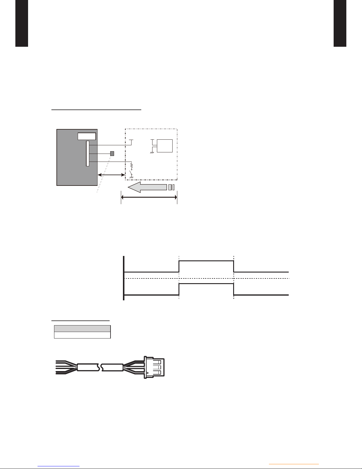
EXTERNAL INPUT
ON/OFF of the "Low noise mode" and "Peak cut mode" functions can be specied by external
signal.
Low noise mode
z
On-site work like the following also reduces the operating sound of the outdoor unit from the •
normal sound.
The air conditioner is set to the "Low noise mode" by applying the contact input of a commercial
timer or ON/OFF switch to a connector on the outdoor control PC board.
* Performance may drop depending on the outside air temperature condition, etc.
Circuit diagram example
Outdoor
control PC board
Connected unit
Connector
1
2
3
Signal
Field supply
* Make the distance from the PC board to the connected unit within 10 m.
Surely insulate with
insulation tape etc. since
this wire is not used.
*10 m
Red
White
Black
Vcc
R
SW
Vcc
Power
supply
Use the following parts and construct a circuit like that shown above. •
Input signal∙∙∙ON : Low noise mode / OFF : Normal operation
•
* Set the "Low noise mode" type by "Push switch" on the outdoor control PC board.
ON
OFF
ON
OFF
Input signal
Low noise mode
Parts (Optional)
Model name
UTY-XWZXZ2
Wire (External input)) : Red / White / Black
1) Power supply
●Voltage (Chart sign=Vcc) : DC 5V to 24V
●The current capacity : About 100mA
2) Switch (Chart sign=SW)
● Toggle switch or Rocker switch, etc : Switch which maintains the
states.
● Pr ep are sw itc he s whi ch a re e no ugh c ap ab le for DC 10mA
current or more
3) Resistance (Chart sign=R)
●Adjust the resistanc e for current to about DC 10mA
(Example)
●In case of Vcc= DC 5V : Rated resistance value 470Ω 1/4W
●In case of Vcc= DC 12V : Rated resistance value 1kΩ 1/4W
●In case of Vcc= DC 24V : Rated resistance value 2.2kΩ 1/4W
- (OU01 - 17) -
Outdoor unit / 3 phase
OUTDOOR UNIT
WO
K112-160LCTA
OUTDOOR UNIT
WO
K112-160LCTA
Peak cut mode
z
Operation that suppressed the current value can be performed by means of the following on- •
site work. The air conditioner is set to the Peak cut mode by applying the contact input of a
commercial ON/OFF switch to a connector on the outdoor control PC board.
Circuit diagram example
Outdoor
control PC board
Connected unit
Connector
1
2
3
Signal
Field supply
* Make the distance from the PC board to the connected unit within 10 m.
Surely insulate with
insulation tape etc. since
this wire is not used.
*10 m
Red
White
Black
Vcc
R
SW
Vcc
Power
supply
Use the following parts and construct a circuit like that shown above. •
Input signal∙∙∙ON: Peak cut mode/OFF: Normal operation
•
*Set the "Peak cut mode" type by "Push switch" on the outdoor control PC board.
ON
OFF
ON
OFF
Input signal
Peak cut mode
Parts (Optional)
Model name
UTY-XWZXZ2
Wire (External input)) : Red / White / Black
1) Power supply
●Voltage (Chart sign=Vcc) : DC 5V to 24V
●The current capacity : About 100mA
2) Switch (Chart sign=SW)
● Toggle switch or Rocker switch, etc : Switch which maintains the
states.
● Pr ep are sw itc he s whi ch a re e no ugh c ap ab le for DC 10mA
current or more
3) Resistance (Chart sign=R)
●Adjust the resistanc e for current to about DC 10mA
(Example)
●In case of Vcc= DC 5V : Rated resistance value 470Ω 1/4W
●In case of Vcc= DC 12V : Rated resistance value 1kΩ 1/4W
●In case of Vcc= DC 24V : Rated resistance value 2.2kΩ 1/4W

- (OU01 - 18) -
Outdoor unit / 3 phase
OUTDOOR UNIT
WO
K112-160LCTA
OUTDOOR UNIT
WO
K112-160LCTA
EXTERNAL OUTPUT
Compressor status output
z
Compressor operation status signal can be output by means of the following on-site work. •
Circuit diagram example
Signal
Outdoor
control PC board
Connected unit
Connector
1
2
3
Field supply
* Make the distance from the PC board to the connected unit within 10 m.
Surely insulate with
insulation tape etc. since
this wire is not used.
*10 m
Red
White
Black
Vcc
+
+
-
Load
Vcc
Power
supply
ON
OFF
Operation
Stop
Compressor status
Output Signal
Parts (Optional)
Model name
UTY-XWZXZ2
Wire (External input)) : Red / White / Black
1) Power supply
●Voltage (Chart sign=Vcc) : DC 24V or less
2) Load
● Load : DC 20mA or less

- (OU01 - 19) -
Outdoor unit / 3 phase
OUTDOOR UNIT
WO
K112-160LCTA
OUTDOOR UNIT
WO
K112-160LCTA
CAPACITY TABLES61
HEATING CAPACITY6-11
MODEL : WOK112LCTA
FT 30°C 35°C 40°C 45°C 50°C 55°C 60°C
OT HC IP COP HC IP COP HC IP COP HC IP COP HC IP COP HC IP COP HC IP COP
-25°C 5.92 3.51 1.69 5.82 3.85 1.51 5.45 3.98 1.37 5.09 4.10 1.24 4.72 4.23 1.12 – – – – – –
-24°C 7.10 4.01 1.77 7.06 4.27 1.65 6.74 4.44 1.52 6.24 4.55 1.37 6.38 5.25 1.22 – – – – – –
-23°C 8.27 4.51 1.83 8.29 4.68 1.77 8.02 4.90 1.64 7.40 5.00 1.48 6.72 5.25 1.28 – – – – – –
-22°C 8.78 4.58 1.92 8.82 4.77 1.85 8.48 5.01 1.69 7.82 5.08 1.54 7.05 5.25 1.34 6.36 5.25 1.21 – – –
-21°C 9.29 4.65 2.00 9.36 4.86 1.93 8.94 5.13 1.74 8.24 5.17 1.59 7.39 5.25 1.41 6.53
5.25 1.24 – – –
-20°C 9.80 4.72 2.08 9.89 4.95 2.00 9.40 5.24 1.79 8.66 5.25 1.65 7.72 5.25 1.47 6.70 5.25 1.28 5.92 5.25 1.13
-19°C 9.96 4.69 2.12 9.99 4.90 2.04 9.56 5.20 1.84 8.92 5.25 1.70 7.99 5.25 1.52 6.98 5.25 1.33 6.14 5.25 1.17
-18°C 10.11 4.66 2.17 10.09 4.85 2.08 9.71 5.16 1.88 9.19 5.25 1.75 8.25 5.25 1.57 7.26 5.25 1.38 6.36 5.25 1.21
-17°C 10.27 4.64 2.21 10.18 4.80 2.12 9.87 5.13 1.92 9.45 5.25 1.80 8.52 5.25 1.62 7.54 5.25 1.44 6.58 5.25 1.25
-16°C 10.42 4.61 2.26 10.28 4.75 2.16 10.02 5.09 1.97 9.72 5.25 1.85 8.78 5.25 1.67 7.82 5.25 1.49 6.80 5.25 1.30
-15°C 10.58 4.58 2.31 10.38 4.70 2.21 10.18 5.05 2.02 9.98 5.25 1.90 9.05 5.25 1.72 8.10 5.25 1.54
7.02 5.25 1.34
-14°C 10.58 4.52 2.34 10.38 4.65 2.23 10.18 4.98 2.04 9.98 5.17 1.93 9.12 5.20 1.75 8.25 5.23 1.58 7.20 5.25 1.37
-13°C 10.58 4.46 2.37 10.38 4.60 2.26 10.18 4.90 2.08 9.98 5.10 1.96 9.20 5.15 1.79 8.39 5.21 1.61 7.39 5.25 1.41
-12°C 10.58 4.40 2.40 10.38 4.54 2.29 10.18 4.83 2.11 9.98 5.02 1.99 9.27 5.10 1.82 8.54 5.19 1.65 7.57 5.25 1.44
-11°C 10.58 4.35 2.43 10.38 4.49 2.31 10.18 4.76 2.14 9.98 4.94 2.02 9.34 5.06 1.85 8.69 5.17 1.68 7.75 5.25 1.48
-10°C 10.58 4.29 2.47 10.38 4.44 2.34 10.18 4.68 2.18 9.98 4.86 2.05 9.41 5.01 1.88 8.83 5.15 1.71 7.93 5.25 1.51
-9°C 10.58 4.23 2.50 10.38 4.39 2.36 10.18 4.61 2.21 9.98 4.79 2.08 9.49 4.96 1.91 8.98 5.13 1.75 8.12 5.25
1.55
-8°C 10.58 4.17 2.54 10.38 4.33 2.40 10.18 4.53 2.25 9.98 4.71 2.12 9.56 4.91 1.95 9.12 5.11 1.78 8.30 5.25 1.58
-7°C 10.58 4.11 2.57 10.38 4.28 2.43 10.18 4.46 2.28 9.98 4.63 2.16 9.63 4.86 1.98 9.27 5.09 1.82 8.48 5.25 1.61
-6°C 10.64 4.03 2.64 10.42 4.18 2.49 10.20 4.36 2.34 9.97 4.56 2.19 9.64 4.76 2.03 9.27 4.97 1.87 8.67 5.16 1.68
-5°C 10.71 3.94 2.72 10.47 4.09 2.56 10.23 4.26 2.40 9.96 4.49 2.22 9.64 4.66 2.07 9.28 4.85 1.91 8.87 5.08 1.75
-4°C 10.77 3.86 2.79 10.51 3.99 2.63 10.25 4.15 2.47 9.95 4.41 2.26 9.65 4.56 2.12 9.28 4.73 1.96 9.06 4.99 1.82
-3°C 10.83 3.77 2.87 10.55 3.89 2.71 10.27 4.05 2.54 9.94 4.34 2.29 9.65 4.46 2.16 9.28 4.61 2.01 9.25 4.90 1.89
-2°C
10.89 3.69 2.95 10.59 3.79 2.79 10.29 3.95 2.61 9.93 4.27 2.33 9.66 4.36 2.22 9.28 4.49 2.07 9.25 4.76 1.94
-1°C 10.96 3.60 3.04 10.64 3.69 2.88 10.32 3.85 2.68 9.92 4.20 2.36 9.66 4.26 2.27 9.28 4.37 2.12 9.25 4.62 2.00
0°C 11.02 3.52 3.13 10.68 3.60 2.97 10.34 3.74 2.76 9.92 4.12 2.41 9.67 4.15 2.33 9.29 4.24 2.19 9.25 4.48 2.06
1°C 11.09 3.43 3.23 10.73 3.50 3.07 10.37 3.64 2.85 9.91 4.05 2.45 9.67 4.05 2.39 9.29 4.12 2.25 9.25 4.34 2.13
2°C 11.15 3.35 3.33 10.77 3.40 3.17 10.39 3.54 2.94 9.90 3.98 2.49 9.68 3.95 2.45 9.29 4.00 2.32 9.25 4.20 2.20
3°C 11.15 3.25 3.43 10.78 3.18 3.39 10.39 3.36 3.09 9.90 3.76 2.63 9.68 3.82 2.53 9.29 3.93 2.36 9.25 4.09 2.26
4°C 11.15 3.15
3.54 10.79 2.96 3.65 10.39 3.18 3.27 9.90 3.54 2.80 9.68 3.68 2.63 9.29 3.85 2.41 9.25 3.97 2.33
5°C 11.15 3.05 3.66 10.80 2.74 3.94 10.39 3.00 3.46 9.90 3.32 2.98 9.68 3.55 2.73 9.29 3.78 2.46 9.25 3.86 2.40
6°C 11.15 2.68 4.16 10.80 2.63 4.11 10.39 2.88 3.61 9.90 3.15 3.14 9.68 3.46 2.80 9.29 3.54 2.62 9.25 3.85 2.40
7°C 11.15 2.31 4.83 10.80 2.51 4.30 10.39 2.75 3.78 9.90 2.98 3.32 9.68 3.37 2.87 9.29 3.52 2.64 9.25 3.84 2.41
8°C 11.15 2.27 4.91 10.80 2.47 4.37 10.39 2.71 3.83 9.90 2.94 3.37 9.68 3.29 2.94 9.29 3.50 2.65 9.25 3.82 2.42
9°C 11.15 2.22 5.02 10.80 2.42 4.46 10.39 2.66 3.91 9.90 2.89 3.43 9.68 3.22 3.01 9.29 3.48 2.67 9.25 3.81 2.43
10°C 11.15 2.18 5.11 10.80
2.38 4.54 10.39 2.62 3.97 9.90 2.85 3.47 9.68 3.14 3.08 9.29 3.46 2.68 9.25 3.79 2.44
11°C 11.15 2.15 5.19 10.80 2.34 4.62 10.39 2.58 4.03 9.90 2.82 3.51 9.68 3.10 3.12 9.29 3.42 2.72 9.25 3.75 2.47
12°C 11.15 2.11 5.28 10.80 2.30 4.70 10.39 2.54 4.09 9.90 2.78 3.56 9.68 3.06 3.16 9.29 3.38 2.75 9.25 3.71 2.49
13°C 11.15 2.08 5.36 10.80 2.26 4.78 10.39 2.50 4.16 9.90 2.75 3.60 9.68 3.02 3.21 9.29 3.34 2.78 9.25 3.68 2.51
14°C 11.15 2.04 5.47 10.80 2.22 4.86 10.39 2.46 4.22 9.90 2.71 3.65 9.68 2.98 3.25 9.29 3.30 2.82 9.25 3.64 2.54
15°C 11.15 2.01 5.55 10.80 2.18 4.95 10.39 2.42 4.29 9.90 2.68 3.69 9.68 2.94 3.29 9.29 3.26 2.85 9.25 3.60 2.57
16°C 11.15 1.97 5.66 10.80 2.14 5.05
10.39 2.38 4.37 9.90 2.64 3.75 9.68 2.90 3.34 9.29 3.22 2.89 9.25 3.57 2.59
17°C 11.15 1.93 5.78 10.80 2.10 5.14 10.39 2.34 4.44 9.90 2.60 3.81 9.68 2.86 3.38 9.29 3.19 2.91 9.25 3.54 2.61
18°C 11.15 1.90 5.87 10.80 2.06 5.24 10.39 2.29 4.54 9.90 2.55 3.88 9.68 2.82 3.43 9.29 3.15 2.95 9.25 3.52 2.63
19°C 11.15 1.86 5.99 10.80 2.02 5.35 10.39 2.25 4.62 9.90 2.51 3.94 9.68 2.78 3.48 9.29 3.12 2.98 9.25 3.49 2.65
20°C 11.15 1.82 6.13 10.80 1.98 5.45 10.39 2.21 4.70 9.90 2.47 4.01 9.68 2.74 3.53 9.29 3.08 3.02 9.25 3.46 2.67
21°C 11.15 1.80 6.19 10.80 1.96 5.51 10.39 2.19 4.74 9.90 2.45 4.04 9.68 2.71 3.57 9.29 3.05 3.05 9.25 3.43 2.70
22°C 11.15 1.79 6.23 10.80 1.94 5.57 10.39 2.17
4.79 9.90 2.42 4.09 9.68 2.69 3.60 9.29 3.02 3.08 9.25 3.40 2.72
23°C 11.15 1.77 6.30 10.80 1.92 5.63 10.39 2.15 4.83 9.90 2.40 4.13 9.68 2.66 3.64 9.29 2.99 3.11 9.25 3.36 2.75
24°C 11.15 1.75 6.37 10.80 1.90 5.68 10.39 2.12 4.90 9.90 2.37 4.18 9.68 2.64 3.67 9.29 2.96 3.14 9.25 3.33 2.78
25°C 11.15 1.74 6.41 10.80 1.88 5.74 10.39 2.10 4.95 9.90 2.35 4.21 9.68 2.61 3.71 9.29 2.93 3.17 9.25 3.30 2.80
26°C 11.15 1.72 6.48 10.80 1.86 5.81 10.39 2.08 5.00 9.90 2.33 4.25 9.68 2.59 3.74 9.29 2.90 3.20 9.25 3.27 2.83
27°C 11.15 1.70 6.56 10.80 1.84 5.87 10.39 2.06 5.04 9.90 2.30 4.30 9.68 2.56 3.78 9.29 2.87 3.24 9.25 3.24 2.85
28°C 11.15 1.69 6.60 10.80 1.83 5.90 10.39 2.04 5.09 9.90
2.28 4.34 9.68 2.54 3.81 9.29 2.85 3.26 9.25 3.20 2.89
29°C 11.15 1.67 6.68 10.80 1.81 5.97 10.39 2.02 5.14 9.90 2.25 4.40 9.68 2.51 3.86 9.29 2.82 3.29 9.25 3.17 2.92
30°C 11.15 1.65 6.76 10.80 1.79 6.03 10.39 2.00 5.20 9.90 2.23 4.44 9.68 2.49 3.89 9.29 2.79 3.33 9.25 3.14 2.95
31°C 11.15 1.64 6.80 10.80 1.77 6.10 10.39 1.98 5.25 9.90 2.21 4.48 9.68 2.46 3.93 9.29 2.76 3.37 9.25 3.11 2.97
32°C 11.15 1.62 6.88 10.80 1.75 6.17 10.39 1.95 5.33 9.90 2.18 4.54 9.68 2.44 3.97 9.29 2.73 3.40 9.25 3.08 3.00
33°C 11.15 1.60 6.97 10.80 1.73 6.24 10.39 1.93 5.38 9.90 2.16 4.58 9.68 2.41 4.02 9.29 2.70 3.44 9.25 3.04 3.04
34°C 11.15 1.59 7.01 10.80 1.71 6.32 10.39 1.91 5.44 9.90 2.13 4.65
9.68 2.39 4.05 9.29 2.67 3.48 9.25 3.01 3.07
35°C 11.15 1.57 7.10 10.80 1.69 6.39 10.39 1.89 5.50 9.90 2.11 4.69 9.68 2.36 4.10 9.29 2.64 3.52 9.25 2.98 3.10
FT : Flow temperature
OT : Outdoor temperature
HC : Heating capacity (kW)
IP : Input power (kW)
COP : Coefcient of performance
The values of heating capacity/power input/COP are based on measurement of EN14511 standard;
FT < 45°C : The ow rate obtained during the test at the standard rating conditions of OT 7°C and Water temp. ow/return 35°C / 30°C, 1872 l/h
FT
>
=
45°C : The ow rate obtained during the test at the standard rating conditions of OT 7°C and Water temp. ow/return 45°C / 40°C, 1722 l/h
FT
>
=
55°C : The ow rate obtained during the test at the standard rating conditions of OT 7°C and Water temp. ow/return 55°C / 47°C, 1014 l/h
Usage environment, such as operation of the heating equipment, room temperature, and controller adjustments, may cause disparities between practically determined and measured
values.

- (OU01 - 20) -
Outdoor unit / 3 phase
OUTDOOR UNIT
WO
K112-160LCTA
OUTDOOR UNIT
WO
K112-160LCTA
MODEL : WOK140LCTA
FT 30°C 35°C 40°C 45°C 50°C 55°C 60°C
OT HC IP COP HC IP COP HC IP COP HC IP COP HC IP COP HC IP COP HC IP COP
-25°C 5.99 3.54 1.69 5.90 3.92 1.51 5.70 4.20 1.36 5.50 4.47 1.23 5.30 4.75 1.12 – – – – – –
-24°C 7.33 4.18 1.75 7.34 4.46 1.65 7.34 4.84 1.52 7.13 5.18 1.38 7.92 6.19 1.28 – – – – – –
-23°C 8.66 4.81 1.80 8.77 4.99 1.76 8.98 5.48 1.64 8.76 5.88 1.49 8.17 6.19 1.32 – – – – – –
-22°C 9.07 4.83 1.88 9.18 5.02 1.83 9.25 5.52 1.68 9.04 5.92 1.53 8.42 6.18 1.36 7.75 6.15 1.26 – – –
-21°C 9.49 4.86 1.95 9.59 5.06 1.90 9.53 5.56 1.71 9.32 5.96 1.56 8.67 6.18 1.40 7.90
6.17 1.28 – – –
-20°C 9.90 4.88 2.03 10.00 5.09 1.96 9.80 5.60 1.75 9.60 6.00 1.60 8.92 6.17 1.45 8.05 6.18 1.30 7.20 6.20 1.16
-19°C 10.37 4.98 2.08 10.42 5.18 2.01 10.11 5.66 1.79 9.83 5.99 1.64 9.20 6.19 1.49 8.33 6.20 1.34 7.47 6.23 1.20
-18°C 10.84 5.07 2.14 10.84 5.27 2.06 10.43 5.72 1.82 10.06 5.98 1.68 9.48 6.21 1.53 8.61 6.23 1.38 7.73 6.26 1.23
-17°C 11.30 5.17 2.19 11.26 5.35 2.10 10.74 5.79 1.85 10.28 5.97 1.72 9.76 6.23 1.57 8.88 6.25 1.42 8.00 6.29 1.27
-16°C 11.77 5.26 2.24 11.68 5.44 2.15 11.06 5.85 1.89 10.51 5.96 1.76 10.04 6.25 1.61 9.16 6.28 1.46 8.26 6.32 1.31
-15°C 12.24 5.36 2.28 12.10 5.53 2.19 11.37 5.91 1.92 10.74 5.95 1.81 10.32 6.27 1.65 9.44 6.30 1.50
8.53 6.35 1.34
-14°C 12.24 5.32 2.30 12.11 5.48 2.21 11.37 5.81 1.96 10.74 5.85 1.84 10.32 6.16 1.68 9.52 6.22 1.53 8.69 6.29 1.38
-13°C 12.24 5.27 2.32 12.13 5.43 2.23 11.37 5.71 1.99 10.74 5.75 1.87 10.32 6.04 1.71 9.61 6.14 1.57 8.84 6.24 1.42
-12°C 12.24 5.23 2.34 12.14 5.38 2.26 11.37 5.60 2.03 10.74 5.65 1.90 10.32 5.93 1.74 9.69 6.06 1.60 9.00 6.18 1.46
-11°C 12.24 5.19 2.36 12.15 5.33 2.28 11.37 5.50 2.07 10.74 5.56 1.93 10.32 5.81 1.78 9.77 5.98 1.63 9.16 6.13 1.49
-10°C 12.24 5.14 2.38 12.16 5.28 2.30 11.37 5.40 2.11 10.74 5.46 1.97 10.32 5.70 1.81 9.85 5.89 1.67 9.31 6.07 1.53
-9°C 12.24 5.10 2.40 12.18 5.23 2.33 11.37 5.30 2.15 10.74 5.36 2.00 10.32 5.58 1.85 9.94 5.81 1.71 9.47 6.01
1.58
-8°C 12.24 5.05 2.42 12.19 5.18 2.35 11.37 5.19 2.19 10.74 5.26 2.04 10.32 5.47 1.89 10.02 5.73 1.75 9.62 5.96 1.61
-7°C 12.24 5.01 2.44 12.20 5.13 2.38 11.37 5.09 2.23 10.74 5.16 2.08 10.32 5.35 1.93 10.10 5.65 1.79 9.78 5.90 1.66
-6°C 12.35 4.90 2.52 12.29 5.02 2.45 11.52 5.03 2.29 10.89 5.15 2.11 10.44 5.33 1.96 10.16 5.60 1.81 9.79 5.82 1.68
-5°C 12.47 4.79 2.60 12.38 4.91 2.52 11.68 4.98 2.35 11.04 5.14 2.15 10.55 5.31 1.99 10.21 5.54 1.84 9.80 5.74 1.71
-4°C 12.58 4.68 2.69 12.47 4.80 2.60 11.83 4.92 2.40 11.19 5.13 2.18 10.67 5.28 2.02 10.27 5.49 1.87 9.80 5.66 1.73
-3°C 12.69 4.57 2.78 12.56 4.69 2.68 11.98 4.86 2.47 11.34 5.12 2.21 10.78 5.26 2.05 10.32 5.43 1.90 9.81 5.58 1.76
-2°C
12.80 4.46 2.87 12.65 4.58 2.76 12.13 4.80 2.53 11.49 5.11 2.25 10.90 5.24 2.08 10.38 5.37 1.93 9.82 5.50 1.79
-1°C 12.91 4.35 2.97 12.74 4.47 2.85 12.29 4.75 2.59 11.64 5.10 2.28 11.01 5.22 2.11 10.43 5.32 1.96 9.83 5.42 1.81
0°C 13.03 4.24 3.07 12.82 4.37 2.93 12.44 4.69 2.65 11.80 5.10 2.31 11.13 5.19 2.14 10.49 5.26 1.99 9.83 5.34 1.84
1°C 13.14 4.13 3.18 12.91 4.26 3.03 12.60 4.64 2.72 11.95 5.09 2.35 11.24 5.17 2.17 10.54 5.21 2.02 9.84 5.26 1.87
2°C 13.25 4.02 3.30 13.00 4.15 3.13 12.75 4.58 2.78 12.10 5.08 2.38 11.36 5.15 2.21 10.60 5.15 2.06 9.85 5.18 1.90
3°C 13.48 4.02 3.35 13.17 4.15 3.17 12.77 4.55 2.81 12.10 4.73 2.56 11.36 4.90 2.32 10.60 4.93 2.15 9.85 5.02 1.96
4°C 13.72 4.02
3.41 13.33 4.15 3.21 12.79 4.52 2.83 12.10 4.38 2.76 11.36 4.65 2.44 10.60 4.72 2.25 9.85 4.85 2.03
5°C 13.95 4.02 3.47 13.50 4.15 3.25 12.81 4.49 2.85 12.10 4.03 3.00 11.36 4.40 2.58 10.60 4.50 2.36 9.85 4.69 2.10
6°C 13.95 3.50 3.99 13.50 3.68 3.67 12.81 3.99 3.21 12.10 3.91 3.09 11.36 4.25 2.67 10.60 4.45 2.38 9.85 4.56 2.16
7°C 13.95 2.98 4.68 13.50 3.20 4.22 12.81 3.49 3.67 12.10 3.78 3.20 11.36 4.09 2.78 10.60 4.40 2.41 9.85 4.42 2.23
8°C 13.95 2.92 4.78 13.50 3.15 4.29 12.81 3.44 3.72 12.10 3.72 3.25 11.36 4.03 2.82 10.60 4.33 2.45 9.85 4.35 2.26
9°C 13.95 2.86 4.88 13.50 3.10 4.35 12.81 3.38 3.79 12.10 3.67 3.30 11.36 3.96 2.87 10.60 4.26 2.49 9.85 4.28 2.30
10°C 13.95 2.80 4.98 13.50
3.05 4.43 12.81 3.33 3.85 12.10 3.61 3.35 11.36 3.90 2.91 10.60 4.19 2.53 9.85 4.21 2.34
11°C 13.95 2.75 5.07 13.50 3.00 4.50 12.81 3.27 3.92 12.10 3.55 3.41 11.36 3.84 2.96 10.60 4.12 2.57 9.85 4.14 2.38
12°C 13.95 2.71 5.15 13.50 2.95 4.58 12.81 3.22 3.98 12.10 3.50 3.46 11.36 3.77 3.01 10.60 4.05 2.62 9.85 4.07 2.42
13°C 13.95 2.66 5.24 13.50 2.89 4.67 12.81 3.16 4.05 12.10 3.44 3.52 11.36 3.71 3.06 10.60 3.97 2.67 9.85 4.00 2.46
14°C 13.95 2.62 5.32 13.50 2.84 4.75 12.81 3.11 4.12 12.10 3.39 3.57 11.36 3.64 3.12 10.60 3.90 2.72 9.85 3.93 2.51
15°C 13.95 2.57 5.43 13.50 2.79 4.84 12.81 3.05 4.20 12.10 3.33 3.63 11.36 3.58 3.17 10.60 3.83 2.77 9.85 3.86 2.55
16°C 13.95 2.52 5.54 13.50 2.74 4.93
12.81 3.00 4.27 12.10 3.28 3.69 11.36 3.53 3.22 10.60 3.78 2.80 9.85 3.83 2.57
17°C 13.95 2.47 5.65 13.50 2.69 5.02 12.81 2.95 4.34 12.10 3.23 3.75 11.36 3.48 3.26 10.60 3.73 2.84 9.85 3.79 2.60
18°C 13.95 2.43 5.74 13.50 2.63 5.13 12.81 2.90 4.42 12.10 3.19 3.79 11.36 3.44 3.30 10.60 3.69 2.87 9.85 3.76 2.62
19°C 13.95 2.38 5.86 13.50 2.58 5.23 12.81 2.85 4.49 12.10 3.14 3.85 11.36 3.39 3.35 10.60 3.64 2.91 9.85 3.72 2.65
20°C 13.95 2.33 5.99 13.50 2.53 5.34 12.81 2.80 4.58 12.10 3.09 3.91 11.36 3.34 3.40 10.60 3.59 2.95 9.85 3.69 2.67
21°C 13.95 2.30 6.07 13.50 2.49 5.42 12.81 2.76 4.64 12.10 3.04 3.98 11.36 3.29 3.45 10.60 3.54 2.99 9.85 3.65 2.70
22°C 13.95 2.26 6.17 13.50 2.46 5.49 12.81 2.71
4.73 12.10 2.99 4.05 11.36 3.24 3.51 10.60 3.50 3.03 9.85 3.62 2.72
23°C 13.95 2.23 6.26 13.50 2.42 5.58 12.81 2.67 4.80 12.10 2.94 4.12 11.36 3.19 3.56 10.60 3.45 3.07 9.85 3.58 2.75
24°C 13.95 2.20 6.34 13.50 2.38 5.67 12.81 2.62 4.89 12.10 2.88 4.20 11.36 3.14 3.62 10.60 3.41 3.11 9.85 3.54 2.78
25°C 13.95 2.17 6.43 13.50 2.34 5.77 12.81 2.58 4.97 12.10 2.83 4.28 11.36 3.09 3.68 10.60 3.36 3.15 9.85 3.50 2.81
26°C 13.95 2.13 6.55 13.50 2.31 5.84 12.81 2.54 5.04 12.10 2.78 4.35 11.36 3.04 3.74 10.60 3.31 3.20 9.85 3.47 2.84
27°C 13.95 2.10 6.64 13.50 2.27 5.95 12.81 2.49 5.14 12.10 2.73 4.43 11.36 2.99 3.80 10.60 3.27 3.24 9.85 3.43 2.87
28°C 13.95 2.07 6.74 13.50 2.23 6.05 12.81 2.45 5.23 12.10
2.68 4.51 11.36 2.94 3.86 10.60 3.22 3.29 9.85 3.39 2.91
29°C 13.95 2.04 6.84 13.50 2.19 6.16 12.81 2.40 5.34 12.10 2.63 4.60 11.36 2.89 3.93 10.60 3.18 3.33 9.85 3.35 2.94
30°C 13.95 2.00 6.98 13.50 2.16 6.25 12.81 2.36 5.43 12.10 2.58 4.69 11.36 2.84 4.00 10.60 3.13 3.39 9.85 3.32 2.97
31°C 13.95 1.97 7.08 13.50 2.12 6.37 12.81 2.32 5.52 12.10 2.53 4.78 11.36 2.79 4.07 10.60 3.08 3.44 9.85 3.28 3.00
32°C 13.95 1.94 7.19 13.50 2.08 6.49 12.81 2.27 5.64 12.10 2.47 4.90 11.36 2.74 4.15 10.60 3.04 3.49 9.85 3.24 3.04
33°C 13.95 1.91 7.30 13.50 2.04 6.62 12.81 2.23 5.74 12.10 2.42 5.00 11.36 2.69 4.22 10.60 2.99 3.55 9.85 3.20 3.08
34°C 13.95 1.87 7.46 13.50 2.01 6.72 12.81 2.18 5.88 12.10 2.37 5.11
11.36 2.64 4.30 10.60 2.95 3.59 9.85 3.17 3.11
35°C 13.95 1.84 7.58 13.50 1.97 6.85 12.81 2.14 6.00 12.10 2.32 5.21 11.36 2.59 4.39 10.60 2.90 3.66 9.85 3.13 3.15
FT : Flow temperature
OT : Outdoor temperature
HC : Heating capacity (kW)
IP : Input power (kW)
COP : Coefcient of performance
The values of heating capacity/power input/COP are based on measurement of EN14511 standard;
FT < 45°C : The ow rate obtained during the test at the standard rating conditions of OT 7°C and Water temp. ow/return 35°C / 30°C, 2339 l/h
FT
>
=
45°C : The ow rate obtained during the test at the standard rating conditions of OT 7°C and Water temp. ow/return 45°C / 40°C, 2105 l/h
FT
>
=
55°C : The ow rate obtained during the test at the standard rating conditions of OT 7°C and Water temp. ow/return 55°C / 47°C, 1157 l/h
Usage environment, such as operation of the heating equipment, room temperature, and controller adjustments, may cause disparities between practically determined and measured
values.

- (OU01 - 21) -
Outdoor unit / 3 phase
OUTDOOR UNIT
WO
K112-160LCTA
OUTDOOR UNIT
WO
K112-160LCTA
MODEL : WOK160LCTA
FT 30°C 35°C 40°C 45°C 50°C 55°C 60°C
OT HC IP COP HC IP COP HC IP COP HC IP COP HC IP COP HC IP COP HC IP COP
-25°C 6.06 3.59 1.69 5.97 3.98 1.50 5.88 4.37 1.35 5.80 4.76 1.22 5.71 5.15 1.11 – – – – – –
-24°C 7.49 4.24 1.77 7.42 4.52 1.64 7.38 5.08 1.45 7.36 5.48 1.34 8.88 6.76 1.31 – – – – – –
-23°C 8.92 4.89 1.82 8.87 5.06 1.75 8.88 5.78 1.54 8.93 6.19 1.44 9.11 6.77 1.35 – – – – – –
-22°C 9.28 4.92 1.89 9.28 5.11 1.82 9.35 5.82 1.61 9.45 6.32 1.50 9.33 6.78 1.38 8.92 6.98 1.28 – – –
-21°C 9.64 4.96 1.94 9.69 5.17 1.87 9.82 5.86 1.68 9.97 6.45 1.55 9.56 6.79 1.41 9.14
6.98 1.31 – – –
-20°C 10.00 4.99 2.00 10.10 5.22 1.93 10.30 5.90 1.74 10.49 6.58 1.59 9.78 6.80 1.44 9.35 6.98 1.34 8.52 6.98 1.22
-19°C 10.47 5.07 2.07 10.51 5.30 1.98 10.63 5.97 1.78 10.75 6.60 1.63 10.04 6.80 1.48 9.58 6.98 1.37 8.72 6.98 1.25
-18°C 10.94 5.16 2.12 10.92 5.37 2.03 10.97 6.04 1.82 11.01 6.62 1.66 10.30 6.81 1.51 9.80 6.98 1.40 8.91 6.98 1.28
-17°C 11.40 5.24 2.18 11.34 5.45 2.08 11.31 6.11 1.85 11.28 6.64 1.70 10.55 6.81 1.55 10.03 6.98 1.44 9.11 6.98 1.31
-16°C 11.87 5.33 2.23 11.75 5.52 2.13 11.64 6.18 1.88 11.54 6.66 1.73 10.81 6.82 1.59 10.25 6.98 1.47 9.30 6.98 1.33
-15°C 12.34 5.41 2.28 12.16 5.60 2.17 11.98 6.25 1.92 11.80 6.68 1.77 11.07 6.82 1.62 10.48 6.98 1.50
9.50 6.98 1.36
-14°C 12.49 5.39 2.32 12.33 5.58 2.21 12.10 6.17 1.96 11.86 6.58 1.80 11.14 6.73 1.66 10.55 6.89 1.53 9.61 6.92 1.39
-13°C 12.63 5.36 2.36 12.50 5.55 2.25 12.21 6.10 2.00 11.93 6.47 1.84 11.22 6.63 1.69 10.61 6.81 1.56 9.71 6.86 1.42
-12°C 12.78 5.34 2.39 12.66 5.53 2.29 12.33 6.02 2.05 11.99 6.37 1.88 11.29 6.54 1.73 10.68 6.72 1.59 9.82 6.80 1.44
-11°C 12.92 5.32 2.43 12.83 5.50 2.33 12.44 5.94 2.09 12.05 6.27 1.92 11.36 6.45 1.76 10.74 6.64 1.62 9.93 6.75 1.47
-10°C 13.07 5.29 2.47 13.00 5.48 2.37 12.56 5.86 2.14 12.11 6.16 1.97 11.43 6.35 1.80 10.81 6.55 1.65 10.03 6.69 1.50
-9°C 13.21 5.27 2.51 13.17 5.45 2.42 12.67 5.79 2.19 12.18 6.06 2.01 11.51 6.26 1.84 10.87 6.46 1.68 10.14 6.63
1.53
-8°C 13.36 5.24 2.55 13.33 5.43 2.45 12.79 5.71 2.24 12.24 5.95 2.06 11.58 6.16 1.88 10.94 6.38 1.71 10.24 6.57 1.56
-7°C 13.50 5.22 2.59 13.50 5.40 2.50 12.90 5.63 2.29 12.30 5.85 2.10 11.65 6.07 1.92 11.00 6.29 1.75 10.35 6.51 1.59
-6°C 13.56 5.12 2.65 13.50 5.31 2.54 12.93 5.55 2.33 12.35 5.81 2.13 11.75 6.04 1.95 11.14 6.28 1.77 10.53 6.50 1.62
-5°C 13.61 5.02 2.71 13.50 5.22 2.59 12.95 5.48 2.36 12.40 5.78 2.15 11.84 6.01 1.97 11.28 6.27 1.80 10.72 6.49 1.65
-4°C 13.67 4.91 2.78 13.50 5.13 2.63 12.98 5.40 2.40 12.45 5.74 2.17 11.94 5.98 2.00 11.41 6.25 1.83 10.90 6.48 1.68
-3°C 13.72 4.81 2.85 13.50 5.04 2.68 13.00 5.32 2.44 12.50 5.70 2.19 12.03 5.95 2.02 11.55 6.24 1.85 11.08 6.47 1.71
-2°C
13.78 4.71 2.93 13.50 4.90 2.76 13.03 5.24 2.49 12.55 5.66 2.22 12.12 5.92 2.05 11.69 6.23 1.88 11.26 6.46 1.74
-1°C 13.83 4.61 3.00 13.50 4.76 2.84 13.05 5.16 2.53 12.60 5.62 2.24 12.22 5.89 2.07 11.83 6.21 1.90 11.44 6.45 1.77
0°C 13.89 4.50 3.09 13.50 4.62 2.92 13.08 5.09 2.57 12.65 5.59 2.26 12.31 5.86 2.10 11.96 6.20 1.93 11.63 6.45 1.80
1°C 13.94 4.40 3.17 13.50 4.48 3.01 13.10 5.01 2.61 12.70 5.55 2.29 12.41 5.83 2.13 12.10 6.18 1.96 11.81 6.44 1.83
2°C 14.00 4.30 3.26 13.50 4.34 3.11 13.13 4.93 2.66 12.75 5.51 2.31 12.50 5.80 2.16 12.24 6.17 1.98 11.99 6.43 1.86
3°C 14.31 4.33 3.30 13.82 4.41 3.13 13.41 4.91 2.73 12.75 5.31 2.40 12.50 5.70 2.19 12.24 5.95 2.06 11.99 6.15 1.95
4°C 14.62 4.37
3.35 14.14 4.49 3.15 13.68 4.90 2.79 12.75 5.12 2.49 12.50 5.59 2.24 12.24 5.74 2.13 11.99 5.86 2.05
5°C 14.93 4.40 3.39 14.46 4.56 3.17 13.96 4.88 2.86 12.75 4.92 2.59 12.50 5.49 2.28 12.24 5.52 2.22 11.99 5.58 2.15
6°C 15.59 4.02 3.88 14.82 4.13 3.59 13.96 4.36 3.20 12.75 4.45 2.87 12.50 4.97 2.52 12.24 4.94 2.48 11.99 5.48 2.19
7°C 16.26 3.64 4.47 15.17 3.70 4.10 13.96 3.84 3.64 12.75 3.97 3.21 12.50 4.45 2.81 12.24 4.93 2.48 11.99 5.41 2.22
8°C 16.26 3.58 4.54 15.17 3.64 4.17 13.96 3.77 3.70 12.75 3.92 3.25 12.50 4.41 2.83 12.24 4.92 2.49 11.99 5.34 2.25
9°C 16.26 3.53 4.61 15.17 3.58 4.24 13.96 3.70 3.77 12.75 3.86 3.30 12.50 4.38 2.85 12.24 4.91 2.49 11.99 5.26 2.28
10°C 16.26 3.47 4.68 15.17
3.52 4.31 13.96 3.63 3.85 12.75 3.81 3.35 12.50 4.34 2.88 12.24 4.90 2.50 11.99 5.19 2.31
11°C 16.26 3.40 4.78 15.17 3.46 4.38 13.96 3.58 3.90 12.75 3.75 3.40 12.50 4.28 2.92 12.24 4.83 2.53 11.99 5.12 2.34
12°C 16.26 3.32 4.90 15.17 3.40 4.46 13.96 3.52 3.97 12.75 3.70 3.45 12.50 4.22 2.96 12.24 4.77 2.57 11.99 5.05 2.37
13°C 16.26 3.25 5.00 15.17 3.34 4.54 13.96 3.47 4.02 12.75 3.64 3.50 12.50 4.16 3.00 12.24 4.70 2.60 11.99 4.98 2.41
14°C 16.26 3.17 5.13 15.17 3.28 4.63 13.96 3.41 4.09 12.75 3.59 3.55 12.50 4.10 3.05 12.24 4.64 2.64 11.99 4.91 2.44
15°C 16.26 3.10 5.24 15.17 3.22 4.71 13.96 3.36 4.15 12.75 3.53 3.61 12.50 4.04 3.09 12.24 4.57 2.68 11.99 4.84 2.48
16°C 16.26 3.03 5.37 15.17 3.16 4.80
13.96 3.31 4.22 12.75 3.48 3.66 12.50 3.99 3.13 12.24 4.51 2.71 11.99 4.78 2.51
17°C 16.26 2.97 5.47 15.17 3.10 4.89 13.96 3.25 4.30 12.75 3.43 3.72 12.50 3.93 3.18 12.24 4.45 2.75 11.99 4.71 2.55
18°C 16.26 2.90 5.61 15.17 3.03 5.01 13.96 3.20 4.36 12.75 3.39 3.76 12.50 3.88 3.22 12.24 4.39 2.79 11.99 4.65 2.58
19°C 16.26 2.84 5.73 15.17 2.97 5.11 13.96 3.14 4.45 12.75 3.34 3.82 12.50 3.82 3.27 12.24 4.33 2.83 11.99 4.58 2.62
20°C 16.26 2.77 5.87 15.17 2.91 5.21 13.96 3.09 4.52 12.75 3.29 3.88 12.50 3.77 3.32 12.24 4.27 2.87 11.99 4.52 2.65
21°C 16.26 2.72 5.98 15.17 2.86 5.30 13.96 3.03 4.61 12.75 3.23 3.95 12.50 3.70 3.38 12.24 4.20 2.91 11.99 4.46 2.69
22°C 16.26 2.67 6.09 15.17 2.80 5.42 13.96 2.98
4.68 12.75 3.17 4.02 12.50 3.63 3.44 12.24 4.13 2.96 11.99 4.40 2.73
23°C 16.26 2.62 6.21 15.17 2.75 5.52 13.96 2.92 4.78 12.75 3.11 4.10 12.50 3.56 3.51 12.24 4.06 3.01 11.99 4.34 2.76
24°C 16.26 2.58 6.30 15.17 2.70 5.62 13.96 2.86 4.88 12.75 3.05 4.18 12.50 3.49 3.58 12.24 3.98 3.08 11.99 4.28 2.80
25°C 16.26 2.53 6.43 15.17 2.64 5.75 13.96 2.81 4.97 12.75 2.99 4.26 12.50 3.42 3.65 12.24 3.91 3.13 11.99 4.22 2.84
26°C 16.26 2.48 6.56 15.17 2.59 5.86 13.96 2.75 5.08 12.75 2.93 4.35 12.50 3.35 3.73 12.24 3.84 3.19 11.99 4.16 2.88
27°C 16.26 2.43 6.69 15.17 2.54 5.97 13.96 2.69 5.19 12.75 2.87 4.44 12.50 3.28 3.81 12.24 3.77 3.25 11.99 4.10 2.92
28°C 16.26 2.38 6.83 15.17 2.48 6.12 13.96 2.64 5.29 12.75
2.80 4.55 12.50 3.22 3.88 12.24 3.70 3.31 11.99 4.03 2.98
29°C 16.26 2.33 6.98 15.17 2.43 6.24 13.96 2.58 5.41 12.75 2.74 4.65 12.50 3.15 3.97 12.24 3.63 3.37 11.99 3.97 3.02
30°C 16.26 2.28 7.13 15.17 2.38 6.37 13.96 2.52 5.54 12.75 2.68 4.76 12.50 3.08 4.06 12.24 3.56 3.44 11.99 3.91 3.07
31°C 16.26 2.23 7.29 15.17 2.32 6.54 13.96 2.47 5.65 12.75 2.62 4.87 12.50 3.01 4.15 12.24 3.49 3.51 11.99 3.85 3.11
32°C 16.26 2.19 7.42 15.17 2.27 6.68 13.96 2.41 5.79 12.75 2.56 4.98 12.50 2.94 4.25 12.24 3.41 3.59 11.99 3.79 3.16
33°C 16.26 2.14 7.60 15.17 2.22 6.83 13.96 2.35 5.94 12.75 2.50 5.10 12.50 2.87 4.36 12.24 3.34 3.66 11.99 3.73 3.21
34°C 16.26 2.09 7.78 15.17 2.16 7.02 13.96 2.30 6.07 12.75 2.44 5.23
12.50 2.80 4.46 12.24 3.27 3.74 11.99 3.67 3.27
35°C 16.26 2.04 7.97 15.17 2.11 7.19 13.96 2.24 6.23 12.75 2.38 5.36 12.50 2.73 4.58 12.24 3.20 3.83 11.99 3.61 3.32
FT : Flow temperature
OT : Outdoor temperature
HC : Heating capacity (kW)
IP : Input power (kW)
COP : Coefcient of performance
The values of heating capacity/power input/COP are based on measurement of EN14511 standard;
FT < 45°C : The ow rate obtained during the test at the standard rating conditions of OT 7°C and Water temp. ow/return 35°C / 30°C, 2629 l/h
FT
>
=
45°C : The ow rate obtained during the test at the standard rating conditions of OT 7°C and Water temp. ow/return 45°C / 40°C, 2218 l/h
FT
>
=
55°C : The ow rate obtained during the test at the standard rating conditions of OT 7°C and Water temp. ow/return 55°C / 47°C, 1336 l/h
Usage environment, such as operation of the heating equipment, room temperature, and controller adjustments, may cause disparities between practically determined and measured
values.
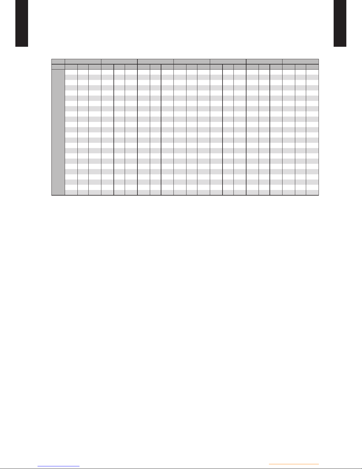
- (OU01 - 22) -
Outdoor unit / 3 phase
OUTDOOR UNIT
WO
K112-160LCTA
OUTDOOR UNIT
WO
K112-160LCTA
COOLING CAPACITY 6-21
*
MODEL : WOK112LCTA
* : OPTIONAL PARTS “Cooling kit" is necessary for cooling operation.
FT : Flow temperature
OT : Outdoor temperature
CC : Cooling capacity (kW)
IP : Input power (kW)
EER : Energy efciency ratio
The values of cooling capacity/power input/COP are based on measurement of EN14511 standard;
FT < 10°C : The ow rate obtained during the test at the standard rating conditions of OT 35°C and Water temp. ow/return 7°C / 12°C, 1464 l/h
FT
>
=
10°C : The ow rate obtained during the test at the standard rating conditions of OT 35°C and Water temp. ow/return 18°C / 23°C, 1691 l/h
Usage environment, such as operation of the heating equipment, room temperature, and controller adjustment, determined and measured may cause disparities between practically
values.
FT 6 °C 7 °C 10 °C 13 °C 15 °C 18 °C 22 °C
OT CC IP EER CC IP EER CC IP EER CC IP EER CC IP EER CC IP EER CC IP EER
20 °C 8.38 2.40 3.49 8.50 2.31 3.69 8.85 2.12 4.17 9.21 1.98 4.66 9.45 1.96 4.82 9.80 1.91 5.13 10.27 1.90 5.40
21 °C 8.38 2.49 3.37 8.50 2.41 3.53 8.85 2.21 4.00 9.21 2.02 4.56 9.45 1.98 4.77 9.80 1.92 5.10 10.27 1.91 5.38
22 °C 8.38 2.59 3.24 8.50 2.52 3.37 8.85 2.30 3.85 9.21 2.07 4.45 9.45 2.01 4.70 9.80 1.93 5.08 10.27 1.92 5.35
23 °C 8.38 2.68 3.12 8.50 2.62 3.24 8.85 2.40 3.70 9.21 2.12 4.34 9.45 2.03 4.66 9.80 1.94 5.06 10.27 1.93 5.32
24 °C 8.38 2.78 3.01 8.50 2.72 3.13 8.85 2.49 3.55 9.21 2.17 4.24 9.45 2.05 4.61 9.80 1.95 5.03 10.27 1.94 5.29
25 °C 8.38 2.42 3.46 8.50 2.35 3.62 8.85 2.16 4.10 9.21 1.96 4.70 9.45 1.82 5.19 9.80 1.63 6.01 10.27 1.37 7.50
26 °C 8.38 2.52 3.33 8.50 2.46 3.46 8.85 2.26 3.92 9.21 2.06 4.47 9.45 1.92 4.92 9.80 1.72 5.70 10.27 1.46 7.03
27 °C 8.38 2.63 3.19 8.50 2.56 3.32 8.85 2.36 3.75 9.21 2.15 4.28 9.45 2.02 4.69 9.80 1.82 5.40 10.27 1.55 6.65
28 °C 8.38 2.74 3.06 8.50 2.67 3.18 8.85 2.46 3.60 9.21 2.25 4.09 9.45 2.11 4.48 9.80 1.91 5.13 10.27 1.63 6.30
29 °C 8.38 2.84 2.95 8.50 2.77 3.07 8.85 2.56 3.46 9.21 2.35 3.92 9.45 2.21 4.28 9.80 2.00 4.90 10.27 1.72 5.97
30 °C 8.38 2.95 2.84 8.50 2.88 2.95 8.85 2.67 3.31 9.21 2.45 3.76 9.45 2.31 4.09 9.80 2.10 4.67 10.27 1.81 5.67
31 °C 8.38 3.06 2.74 8.50 2.98 2.85 8.85 2.77 3.19 9.21 2.54 3.63 9.45 2.40 3.94 9.80 2.19 4.47 10.27 1.90 5.41
32 °C 8.38 3.16 2.65 8.50 3.09 2.75 8.85 2.87 3.08 9.21 2.64 3.49 9.45 2.50 3.78 9.80 2.28 4.30 10.27 1.99 5.16
33 °C 8.38 3.27 2.56 8.50 3.19 2.66 8.85 2.97 2.98 9.21 2.74 3.36 9.45 2.60 3.63 9.80 2.38 4.12 10.27 2.07 4.96
34 °C 8.38 3.38 2.48 8.50 3.30 2.58 8.85 3.07 2.88 9.21 2.83 3.25 9.45 2.69 3.51 9.80 2.47 3.97 10.27 2.16 4.75
35 °C 8.38 3.49 2.40 8.50 3.41 2.50 8.85 3.17 2.79 9.21 2.93 3.14 9.45 2.79 3.39 9.80 2.57 3.82 10.27 2.25 4.56
36 °C 8.38 3.62 2.31 8.50 3.54 2.40 8.85 3.31 2.67 9.21 3.07 3.00 9.45 2.92 3.24 9.80 2.69
3.64 10.27 2.38 4.32
37 °C 8.38 3.76 2.23 8.50 3.68 2.31 8.85 3.44 2.57 9.21 3.20 2.88 9.45 3.05 3.10 9.80 2.82 3.48 10.27 2.50 4.11
38 °C 8.38 3.89 2.15 8.50 3.82 2.23 8.85 3.58 2.47 9.21 3.34 2.76 9.45 3.18 2.97 9.80 2.95 3.32 10.27 2.63 3.90
39 °C 8.38 4.03 2.08 8.50 3.95 2.15 8.85 3.72 2.38 9.21 3.47 2.65 9.45 3.31 2.85 9.80 3.08 3.18 10.27 2.76 3.72
40 °C 8.29 4.22 1.97 8.50 4.09 2.08 8.85 3.85 2.30 9.21 3.61 2.55 9.45 3.44 2.75 9.80 3.20 3.06 10.27 2.88 3.56
41 °C 8.05 4.23 1.90 8.30 4.14 2.00 8.81 3.99 2.21 9.21 3.74 2.46 9.45 3.57 2.65 9.80 3.33 2.94 10.27 3.01 3.41
42 °C 7.81 4.24 1.84 8.09 4.19 1.93 8.77 4.14 2.12 9.21 3.88 2.37 9.45 3.71 2.55 9.80 3.46 2.83 10.27 3.13 3.28
43 °C 7.57 4.25 1.78 7.89 4.23 1.86 8.73 4.28 2.04 9.21 4.01 2.30 9.45 3.84 2.46 9.80 3.59 2.73 10.27 3.25 3.16

- (OU01 - 23) -
Outdoor unit / 3 phase
OUTDOOR UNIT
WO
K112-160LCTA
OUTDOOR UNIT
WO
K112-160LCTA
MODEL : WOK140LCTA
* : OPTIONAL PARTS “Cooling kit" is necessary for cooling operation.
FT : Flow temperature
OT : Outdoor temperature
CC : Cooling capacity (kW)
IP : Input power (kW)
EER : Energy efciency ratio
The values of cooling capacity/power input/COP are based on measurement of EN14511 standard;
FT < 10°C : The ow rate obtained during the test at the standard rating conditions of OT 35°C and Water temp. ow/return 7°C / 12°C, 1550 l/h
FT
>
=
10°C : The ow rate obtained during the test at the standard rating conditions of OT 35°C and Water temp. ow/return 18°C / 23°C, 2157 l/h
Usage environment, such as operation of the heating equipment, room temperature, and controller adjustments, may cause disparities between practically determined and measured
values.
FT 6 °C 7 °C 10 °C 13 °C 15 °C 18 °C 22 °C
OT CC IP EER CC IP EER CC IP EER CC IP EER CC IP EER CC IP EER CC IP EER
20 °C 8.68 2.52 3.45 9.00 2.54 3.54 9.95 2.71 3.67 10.91 2.84 3.84 11.55 2.89 4.00 12.50 2.87 4.36 13.77 2.90 4.75
21 °C 8.68 2.62 3.31 9.00 2.65 3.40 9.95 2.81 3.54 10.91 2.96 3.69 11.55 2.99 3.86 12.50 2.97 4.21 13.77 3.01 4.57
22 °C 8.68 2.72 3.19 9.00 2.76 3.26 9.95 2.92 3.41 10.91 3.07 3.55 11.55 3.09 3.74 12.50 3.08 4.06 13.77 3.12 4.41
23 °C 8.68 2.82 3.08 9.00 2.87 3.13 9.95 3.02 3.30 10.91 3.18 3.43 11.55 3.19 3.62 12.50 3.18 3.93 13.77 3.23 4.26
24 °C 8.68 2.92 2.97 9.00 2.98 3.02 9.95 3.12 3.19 10.91 3.29 3.32 11.55 3.29 3.51 12.50 3.29 3.80 13.77 3.34 4.12
25 °C 8.68 2.46 3.53 9.00 2.45 3.67 9.95 2.46 4.04 10.91 2.44 4.47 11.55 2.43 4.75 12.50 2.41 5.19 13.77 2.26 6.09
26 °C 8.68 2.58 3.36 9.00 2.57 3.50 9.95 2.57 3.87 10.91 2.56 4.26 11.55 2.55 4.53 12.50 2.53 4.94 13.77 2.40 5.74
27 °C 8.68 2.70 3.21 9.00 2.70 3.34 9.95 2.68 3.71 10.91 2.67 4.09 11.55 2.66 4.35 12.50 2.65 4.72 13.77 2.54 5.42
28 °C 8.68 2.83 3.07 9.00 2.82 3.19 9.95 2.79 3.57 10.91 2.78 3.92 11.55 2.77 4.17 12.50 2.77 4.51 13.77 2.68 5.14
29 °C 8.68 2.95 2.94 9.00 2.94 3.06 9.95 2.90 3.43 10.91 2.89 3.78 11.55 2.88 4.01 12.50 2.89 4.33 13.77 2.82 4.88
30 °C 8.68 3.07 2.83 9.00 3.06 2.94 9.95 3.01 3.31 10.91 3.00 3.64 11.55 3.00 3.85 12.50 3.01 4.15 13.77 2.96 4.65
31 °C 8.68 3.19 2.72 9.00 3.18 2.83 9.95 3.13 3.18 10.91 3.11 3.51 11.55 3.11 3.71 12.50 3.13 3.99 13.77 3.10 4.44
32 °C 8.68 3.32 2.61 9.00 3.30 2.73 9.95 3.24 3.07 10.91 3.22 3.39 11.55 3.22 3.59 12.50 3.25 3.85 13.77 3.24 4.25
33 °C 8.68 3.44 2.52 9.00 3.42 2.63 9.95 3.35 2.97 10.91 3.33 3.28 11.55 3.33 3.47 12.50 3.37 3.71 13.77 3.38 4.07
34 °C 8.68 3.56 2.44 9.00 3.54 2.54 9.95 3.46 2.88 10.91 3.44 3.17 11.55 3.44 3.36 12.50 3.49 3.58 13.77 3.52 3.91
35 °C 8.68 3.69 2.36 9.00 3.66 2.46 9.95 3.57 2.78 10.91 3.55 3.07 11.55 3.56 3.25 12.50 3.61 3.46 13.77 3.67 3.76
36 °C 8.68 3.83 2.27 9.00 3.82 2.36 9.95 3.77 2.64 10.91 3.75 2.91 11.55 3.75 3.08 12.50 3.79
3.30 13.77 3.81 3.61
37 °C 8.68 3.97 2.19 9.00 3.98 2.26 9.95 3.96 2.51 10.91 3.95 2.76 11.55 3.95 2.92 12.50 3.96 3.16 13.77 3.96 3.48
38 °C 8.68 4.11 2.11 9.00 4.13 2.18 9.95 4.15 2.40 10.91 4.15 2.63 11.55 4.15 2.79 12.50 4.14 3.02 13.77 4.11 3.35
39 °C 8.68 4.25 2.04 9.00 4.29 2.10 9.95 4.34 2.29 10.91 4.35 2.51 11.55 4.34 2.66 12.50 4.31 2.90 13.77 4.26 3.23
40 °C 8.30 4.22 1.97 8.62 4.22 2.04 9.57 4.25 2.25 10.51 4.26 2.47 11.14 4.27 2.61 12.09 4.28 2.82 13.35 4.31 3.10
41 °C 8.06 4.23 1.91 8.38 4.23 1.98 9.29 4.26 2.18 10.18 4.27 2.38 10.82 4.28 2.53 11.76 4.30 2.73 12.97 4.33 3.00
42 °C 7.82 4.24 1.84 8.14 4.24 1.92 9.02 4.27 2.11 9.86 4.28 2.30 10.50 4.30 2.44 11.42 4.32 2.64 12.59 4.35 2.89
43 °C 7.58 4.25 1.78 7.90 4.25 1.86 8.74 4.28 2.04 9.53 4.29 2.22 10.18 4.31 2.36 11.09 4.33 2.56 12.21 4.37 2.79

- (OU01 - 24) -
Outdoor unit / 3 phase
OUTDOOR UNIT
WO
K112-160LCTA
OUTDOOR UNIT
WO
K112-160LCTA
MODEL : WOK160LCTA
* : OPTIONAL PARTS “Cooling kit" is necessary for cooling operation.
FT : Flow temperature
OT : Outdoor temperature
CC : Cooling capacity (kW)
IP : Input power (kW)
EER : Energy efciency ratio
The values of cooling capacity/power input/COP are based on measurement of EN14511 standard;
FT < 10°C : The ow rate obtained during the test at the standard rating conditions of OT 35°C and Water temp. ow/return 7°C / 12°C, 1636 l/h
FT
>
=
10°C : The ow rate obtained during the test at the standard rating conditions of OT 35°C and Water temp. ow/return 18°C / 23°C, 2330 l/h
Usage environment, such as operation of the heating equipment, room temperature, and controller adjustments, may cause disparities between practically determined and measured
values.
FT 6 °C 7 °C 10 °C 13 °C 15 °C 18 °C 22 °C
OT CC IP EER CC IP EER CC IP EER CC IP EER CC IP EER CC IP EER CC IP EER
20 °C 9.14 2.70 3.39 9.50 2.78 3.42 10.59 3.06 3.47 11.68 3.24 3.61 12.41 3.27 3.80 13.50 3.22 4.20 14.95 3.21 4.66
21 °C 9.14 2.81 3.25 9.50 2.90 3.28 10.59 3.16 3.35 11.68 3.33 3.51 12.41 3.35 3.70 13.50 3.32 4.07 14.87 3.32 4.48
22 °C 9.14 2.91 3.14 9.50 3.01 3.16 10.59 3.27 3.24 11.68 3.41 3.43 12.41 3.43 3.62 13.33 3.42 3.90 14.78 3.43 4.31
23 °C 9.14 3.02 3.02 9.50 3.13 3.04 10.59 3.38 3.13 11.43 3.50 3.26 12.15 3.52 3.45 13.25 3.53 3.75 14.70 3.54 4.15
24 °C 9.14 3.13 2.92 9.50 3.24 2.93 10.59 3.49 3.03 11.35 3.59 3.16 12.06 3.60 3.35 13.16 3.63 3.63 14.62 3.65 4.01
25 °C 9.14 2.53 3.61 9.50 2.54 3.74 10.59 2.57 4.12 11.68 2.60 4.49 12.41 2.62 4.74 13.50 2.66 5.08 14.95 2.58 5.79
26 °C 9.14 2.68 3.41 9.50 2.68 3.54 10.59 2.72 3.89 11.68 2.75 4.25 12.41 2.77 4.48 13.50 2.81 4.80 14.95 2.73 5.48
27 °C 9.14 2.82 3.24 9.50 2.83 3.36 10.59 2.86 3.70 11.68 2.90 4.03 12.41 2.92 4.25 13.50 2.96 4.57 14.95 2.88 5.20
28 °C 9.14 2.96 3.09 9.50 2.97 3.20 10.59 3.01 3.52 11.68 3.05 3.83 12.41 3.07 4.04 13.50 3.10 4.35 14.95 3.02 4.95
29 °C 9.14 3.10 2.95 9.50 3.12 3.04 10.59 3.16 3.35 11.68 3.20 3.65 12.41 3.22 3.85 13.50 3.25 4.15 14.95 3.17 4.72
30 °C 9.14 3.25 2.81 9.50 3.26 2.91 10.59 3.31 3.20 11.68 3.34 3.50 12.41 3.37 3.68 13.50 3.40 3.97 14.95 3.32 4.50
31 °C 9.14 3.39 2.70 9.50 3.41 2.79 10.59 3.46 3.06 11.68 3.49 3.35 12.41 3.52 3.53 13.50 3.55 3.80 14.95 3.47 4.31
32 °C 9.14 3.53 2.59 9.50 3.56 2.67 10.59 3.61 2.93 11.68 3.64 3.21 12.41 3.67 3.38 13.50 3.69 3.66 14.95 3.62 4.13
33 °C 9.14 3.67 2.49 9.50 3.70 2.57 10.59 3.76 2.82 11.68 3.79 3.08 12.41 3.82 3.25 13.50 3.84 3.52 14.95 3.76 3.98
34 °C 9.14 3.82 2.39 9.50 3.85 2.47 10.59 3.91 2.71 11.68 3.94 2.96 12.41 3.97 3.13 13.50 3.99 3.38 14.95 3.91 3.82
35 °C 9.14 3.96 2.31 9.50 3.99 2.38 10.59 4.06 2.61 11.68 4.09 2.86 12.41 4.12 3.02 13.50 4.14 3.26 14.95 4.06 3.68
36 °C 9.14 4.12 2.22 9.50 4.14 2.29 10.59 4.20 2.52 11.68 4.23 2.76 12.41 4.26 2.91 13.50 4.28
3.15 14.95 4.20 3.56
37 °C 9.14 4.28 2.14 9.50 4.30 2.21 10.59 4.34 2.44 11.68 4.38 2.67 12.41 4.40 2.82 13.50 4.43 3.05 14.95 4.35 3.44
38 °C 9.14 4.44 2.06 9.50 4.45 2.13 10.59 4.49 2.36 11.68 4.52 2.58 12.41 4.54 2.73 13.50 4.58 2.95 14.95 4.49 3.33
39 °C 9.14 4.60 1.99 9.50 4.60 2.07 10.59 4.63 2.29 11.68 4.66 2.51 12.41 4.68 2.65 13.50 4.72 2.86 14.95 4.63 3.23
40 °C 8.31 4.23 1.97 8.63 4.23 2.04 9.58 4.25 2.25 10.52 4.27 2.47 11.15 4.28 2.61 12.10 4.29 2.82 13.36 4.31 3.10
41 °C 8.07 4.24 1.90 8.39 4.24 1.98 9.30 4.26 2.18 10.19 4.28 2.38 10.83 4.29 2.52 11.77 4.31 2.73 12.98 4.33 3.00
42 °C 7.83 4.24 1.85 8.15 4.25 1.92 9.03 4.27 2.11 9.87 4.29 2.30 10.51 4.31 2.44 11.43 4.33 2.64 12.60 4.35 2.90
43 °C 7.59 4.25 1.78 7.91 4.26 1.86 8.75 4.28 2.04 9.54 4.30 2.22 10.19 4.32 2.36 11.10 4.34 2.56 12.22 4.37 2.79
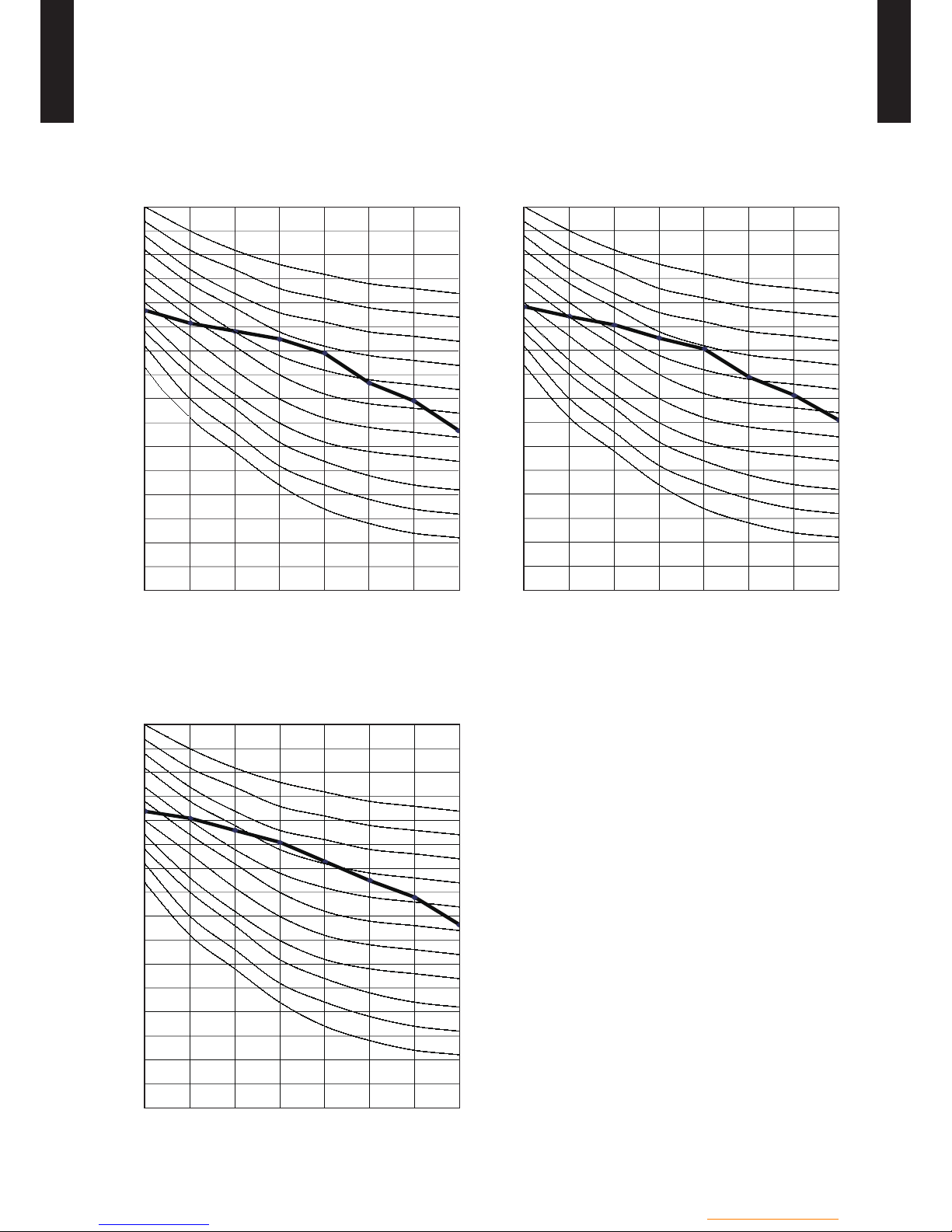
- (OU01 - 25) -
Outdoor unit / 3 phase
OUTDOOR UNIT
WO
K112-160LCTA
OUTDOOR UNIT
WO
K112-160LCTA
OPERATION NOISE71
NOISE LEVEL CURVE7-11
MODEL : WOK160LCTA
Octave band sound pressure level, dB:(0dB=0.0002µbar)
Octave band center frequency,Hz
80
70
60
50
40
30
20
10
0
63 125 250 500 1,000 2,000 4,000 8,000
NC-65
NC-60
NC-55
NC-50
NC-45
NC-40
NC-35
NC-30
NC-25
NC-20
NC-15
Heating
z
Octave band sound pressure level, dB:(0dB=0.0002µbar)
Octave band center frequency,Hz
80
70
60
50
40
30
20
10
0
63 125 250 500 1,000 2,000 4,000 8,000
NC-65
NC-60
NC-55
NC-50
NC-45
NC-40
NC-35
NC-30
NC-25
NC-20
NC-15
Octave band sound pressure level, dB:(0dB=0.0002µbar)
Octave band center frequency,Hz
80
70
60
50
40
30
20
10
0
63 125 250 500 1,000 2,000 4,000 8,000
NC-65
NC-60
NC-55
NC-50
NC-45
NC-40
NC-35
NC-30
NC-25
NC-20
NC-15
MODEL : WOK140LCTA
Heating
z
MODEL : WOK112LCTA
Heating
z

- (OU01 - 26) -
Outdoor unit / 3 phase
OUTDOOR UNIT
WO
K112-160LCTA
OUTDOOR UNIT
WO
K112-160LCTA
SOUND LEVEL CHECK POINT7-21
Microphone
1m
Microphone
Air Flow
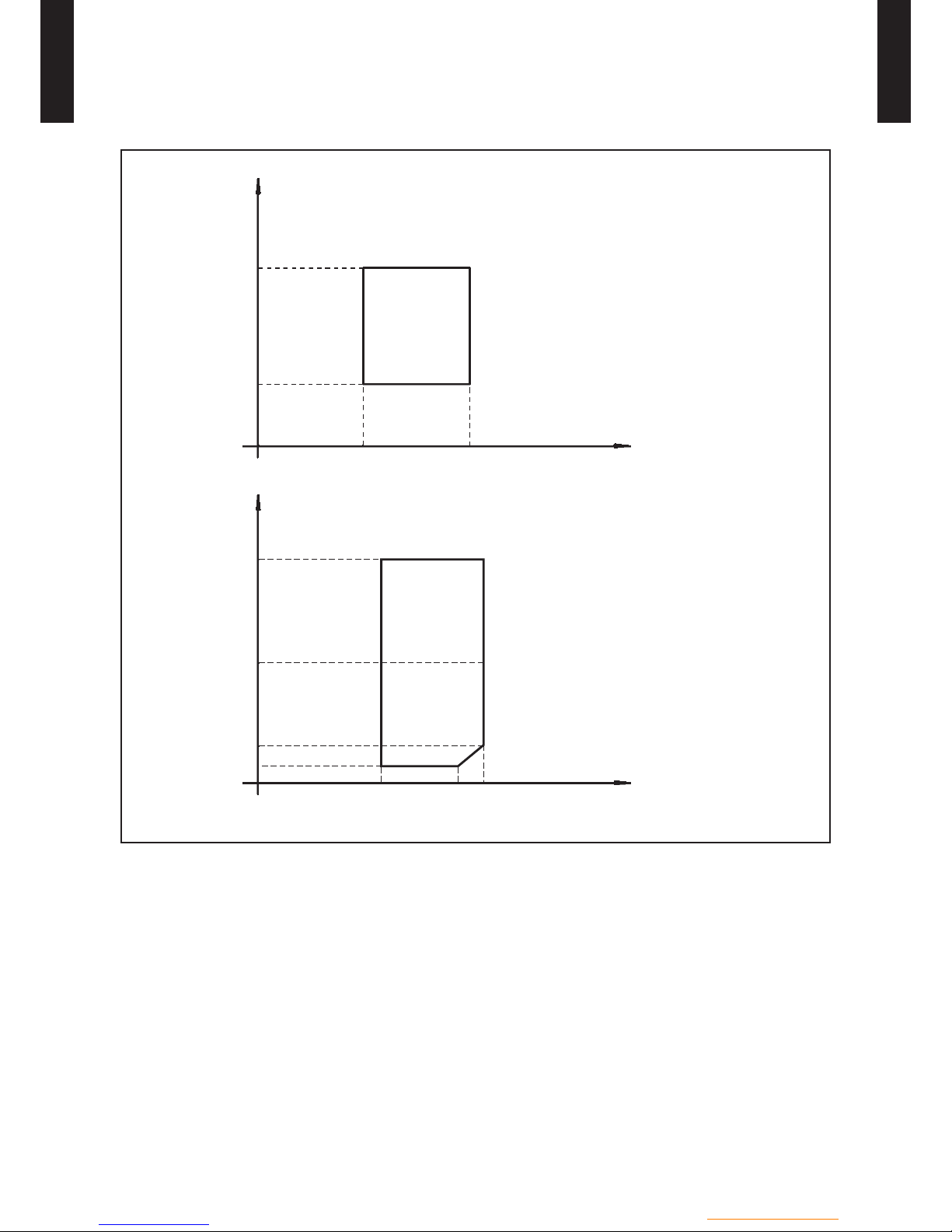
- (OU01 - 27) -
Outdoor unit / 3 phase
OUTDOOR UNIT
WO
K112-160LCTA
OUTDOOR UNIT
WO
K112-160LCTA
OPERATION RANGE81
Cooling mode
Flow temperature (°C)
Flow temperature (°C)
Heating mode
Sanitary mode
Outdoor temperature (°CDB)
43
8
6 35
35
0
-20
-25
8 60
Outdoor temperature (°CDB)
50
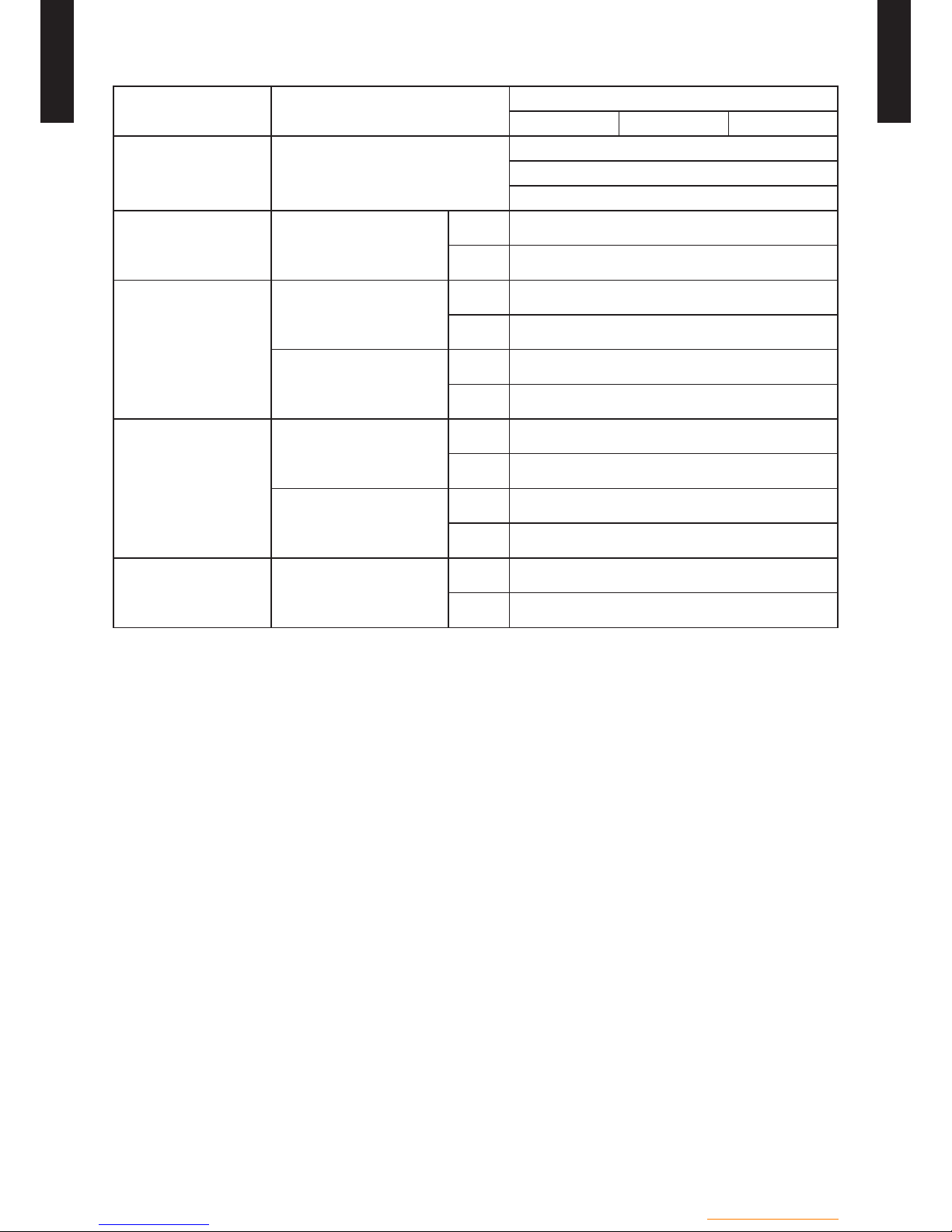
- (OU01 - 28) -
Outdoor unit / 3 phase
OUTDOOR UNIT
WO
K112-160LCTA
OUTDOOR UNIT
WO
K112-160LCTA
SAFETY DEVICES91
Protection from
Model
WOÛK112LCTA WOÛK140LCTA WOÛK160LCTA
Circuit protection Current fuse (Main PCB)
5A 250V
3.15A 250V
10A 250V
Fan motor protection Thermal protecter
Activate
150±20ºC
Fan motor stop
Reset
120±20ºC
Fan motor restart
Compressor protection
Thermal protection program
(Compressor temp.)
Activate
112ºC
Compressor stop
Reset
80ºC
Compressor restart
Thermal protection program
(Discharge temp.)
Activate
115
°C
Compressor stop
Reset
after 7 minutes
Compressor restart
High pressure protection
Thermal protection program
(Heat exchanger temp.)
Activate
68
°C
Compressor stop
Reset
63
°C
Compressor restart
Pressure sensor
Activate
4.2 MPa
Compressor stop
Reset
3.0 MPa
Compressor restart
Low pressure protection
(Cooling mode only)
Pressure sensor
Activate
0.12 MPa
Compressor stop
Reset
0.15 MPa
Compressor restart
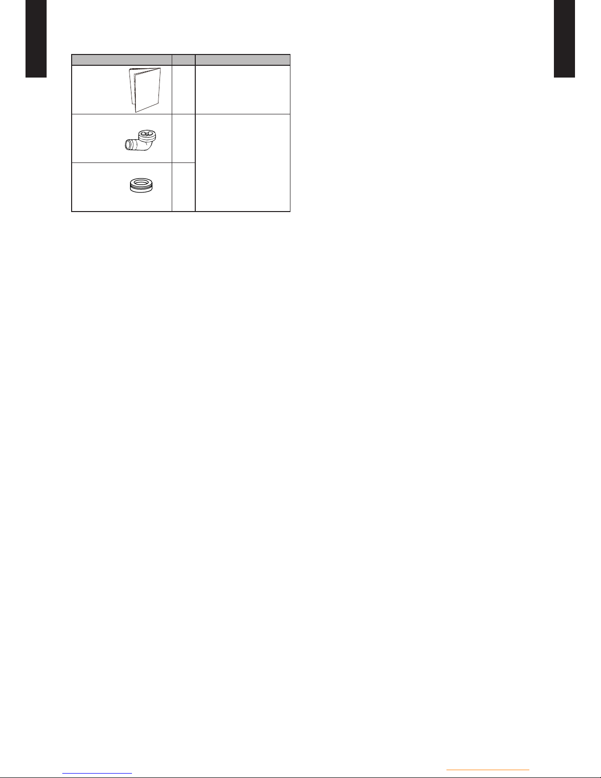
- (OU01 - 29) -
Outdoor unit / 3 phase
OUTDOOR UNIT
WO
K112-160LCTA
OUTDOOR UNIT
WO
K112-160LCTA
STANDARD ACCESSORIES101
Name and shape Q'ty Application
Installation
manual
1
Drain pipe
1
For outdoor unit drain
piping work.
Drain cap
2

3. CONTROL SYSTEM
DTW_SDI003E_01--CHAPTER03
2016.02.18
WGA050DG (Hydraulic unit)
WGA100DG (Hydraulic unit)
WGG140DG (Hydraulic unit)
WGYK160DG9 (Hydraulic unit)

CONTROL
SYSTEM
CONTROL
SYSTEM
CONTENTS
CONTROL SYSTEM33
13 FEATURES
…………………………………………………………………………………
CS01 - 01
23 FUNCTIONS
………………………………………………………………………………
CS01 - 03
2-13 USER INTERFACE AND REMOTE CONTROL (Optional parts)
……………
CS01 - 03
2-23 ROOM THERMOSTAT (Optional parts)
…………………………………………
CS01 - 09
2-33 CONTROL SETTING
……………………………………………………………………
CS01 - 10
33 ELECTRICAL CONNECTIONS
………………………………………………
CS01 - 67
3-13 OVERVIEW OF ALL THE ELECTRICAL CONNECTIONS
……………………
CS01 - 67
3-23 ELECTRICAL CONNECTIONS ON THE HYDRAULIC UNIT
…………………
CS01 - 68
3-33 CONNECTIONS TO THE HEAT PUMP REGULATOR
(Accessories and options)
………………………………………………………
CS01 - 71
43 INSTALLATION
…………………………………………………………………………
CS01 - 79
4-13 OUTDOOR SENSOR
……………………………………………………………………
CS01 - 79
4-23 REMOTE CONTROL (Optional parts)
……………………………………………
CS01 - 80
4-33 ROOM THERMOSTAT (Optional parts)
…………………………………………
CS01 - 84
4-43 RF MODULE (Optional parts)
………………………………………………………
CS01 - 86
53 DIMENSIONS
……………………………………………………………………………
CS01 - 87
5-13 OUTDOOR SENSOR
……………………………………………………………………
CS01 - 87
5-23 REMOTE CONTROL (Optional parts)
……………………………………………
CS01 - 88
5-33 ROOM THERMOSTAT (Optional parts)
…………………………………………
CS01 - 89
5-43 RF MODULE (Optional parts)
………………………………………………………
CS01 - 90
63 PACKING LIST (Accessories)
………………………………………………
CS01 - 92
6-13 REMOTE CONTROL (Optional parts)
……………………………………………
CS01 - 92
6-23 ROOM THERMOSTAT (Optional parts)
…………………………………………
CS01 - 92
6-33 RF MODULE (Optional parts)
………………………………………………………
CS01 - 93
73 WIRING SPECIFICATIONS
……………………………………………………
CS01 - 94
7-13 OUTDOOR SENSOR
……………………………………………………………………
CS01 - 94
7-23 REMOTE CONTROL (Optional parts)
……………………………………………
CS01 - 94
7-33 ROOM THERMOSTAT (Optional parts)
…………………………………………
CS01 - 94
7-43 RF MODULE (Optional parts)
………………………………………………………
CS01 - 94
83 SPECIFICATIONS
……………………………………………………………………
CS01 - 95
8-13 OUTDOOR SENSOR
……………………………………………………………………
CS01 - 95
8-23 REMOTE CONTROL (Optional parts)
……………………………………………
CS01 - 95
8-33 ROOM THERMOSTAT (Optional parts)
…………………………………………
CS01 - 95
8-43 RF MODULE (Optional parts)
………………………………………………………
CS01 - 96
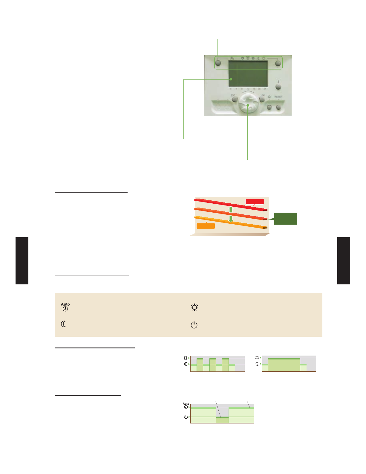
- (CS01 - 01) -
Control system
CONTROL
SYSTEM
CONTROL
SYSTEM
FEATURES13
SMART & COMFORT CONTROL
The outdoor temperature is detected by sensor
and the heating water temperature is controlled
automatically.
The setting of room temperature and operation
mode can be easily set. A wide range of
control from heating to hot water supply and
swimming pool is possible by combining with
various optional parts.
Simple operation mode setting
•Selecting the heating mode
Large LCD display
•Operation status display
•Error display / Error histor y
Navigation and setting
•Selecting the heating menu
•Setting program timer
Comfort
z
Flexible heating circuit
Automatic hot water temperature control
matched to the application can be set.
In addition, set temperature coefcient offset
can be adjusted easily high or low side
matched to the usage conditions.
+
4.5°C
-
4.5°C
Setting
heating curve
Leaving water
temperature (°C)
Outdoo r tempera ture (°C)
High
High
Low
Low
Convenience
z
Programmed operation
The setting of programmed operation can be easily set. -
Changing the heating mode linked with time is possible. -
Heating mode
Automatic mode
Comfort/Reduce mode switching automatically
according to outdoor temperature
Comfort mode
Constant comfort temperature
Reduce mode
Constant reduce temperature
Protection mode
Stand-by mode with anti-frost protection
Day-Weekly timer setting
The day-weekly timer can be set up for up to 3 times per day.
Allows separate settings for each day of the week.
6 9 12 15 18 21 24
6 9 12 15 18 21 24
6 9 12 15 18 21 24
Monday-Friday
Time
Time
Saturday-Sunday
Holiday timer setting
The holiday timer can be set up for up to 8 periods.
If you are absent for a long time in the winter, freezing of room can be prevented.
11 12 1 2 3
Holiday timer Day-Weekly timer
Date

- (CS01 - 02) -
Control system
- (CS01 - 02) -
CONTROL
SYSTEM
CONTROL
SYSTEM
Extendibility
z
Diverse operation control
Meets diverse needs by combining with
optional parts.
OPTIONS
2-temperature simultaneous heating
Floor heating + Radiator heating
(Split type only)
Operation together with boiler
at low outdoor temperature
Temperature control of swimming
pool (Controlled at 35°C)
Remote controller - Extension
Optional remote controller allows controls of
hot water depending on room temperature.
Outdoor
Sensor
Outdoo r unit Hydraulic unit
Room Thermostat
(Option)
Remote control
(Option)
Floor heating Radiator
(Split type)
or
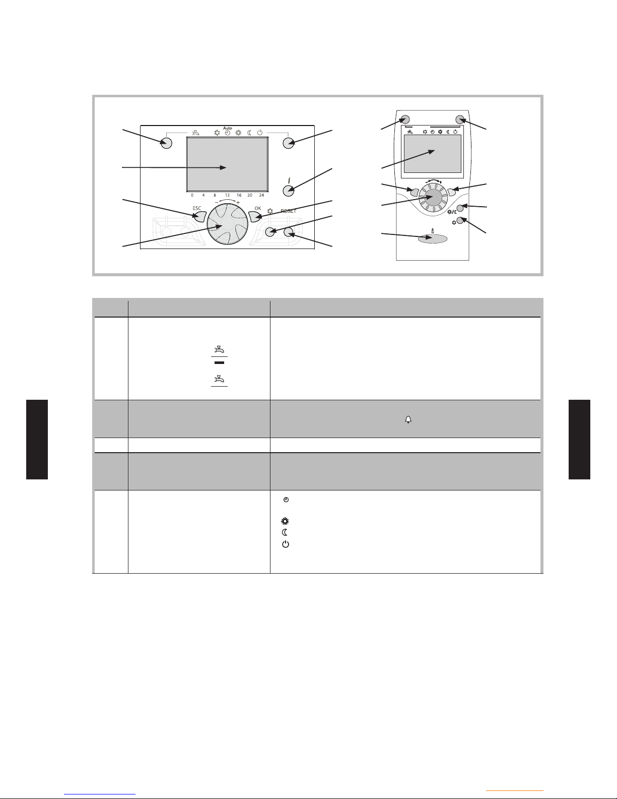
- (CS01 - 03) -
Control system
CONTROL
SYSTEM
CONTROL
SYSTEM
FUNCTIONS23
USER INTERFACE 2-13
AND REMOTE CONTROL (Optional parts)
Auto
ESC
OK
0 4 8 12 16 20 24
1
2
3
4
5 1
2
3
4
6
5
7
12
8
6
7
8
9
Ref 3 Functions - Denitions
1 Selecting DHW operating mode
(Domestic Hot Water)
On
Off
If the installation is tted with a DHW tank. On : Production of DHW according to the time program. Off : Preparing the domestic hot water for stopping with the -
anti-frost function active.
Manual start button : Hold down the DHW key for 3 seconds. Switch from "reduced" to "comfort" until the next time the
DHW timer switches over.
2 Digital display Operating control. Readout of the current temperature, the
heating mode and any faults .
View the settings -
3 Exit "ESC" Quit the menu.
-
4 Navigation and setting Selecting the menu.
Setting parameters. Adjusting the ambient temperature setpoint. -
5 Selecting heating mode
Auto
- Heating operation according to the heating program
(Summer/Winter mode switchover is automatic).
- Constant comfort temperature.
- Constant reduced temperature.
- Stand-by mode with anti-frost protection
(Provided that the heat pump's electrical power supply is not
interrupted).
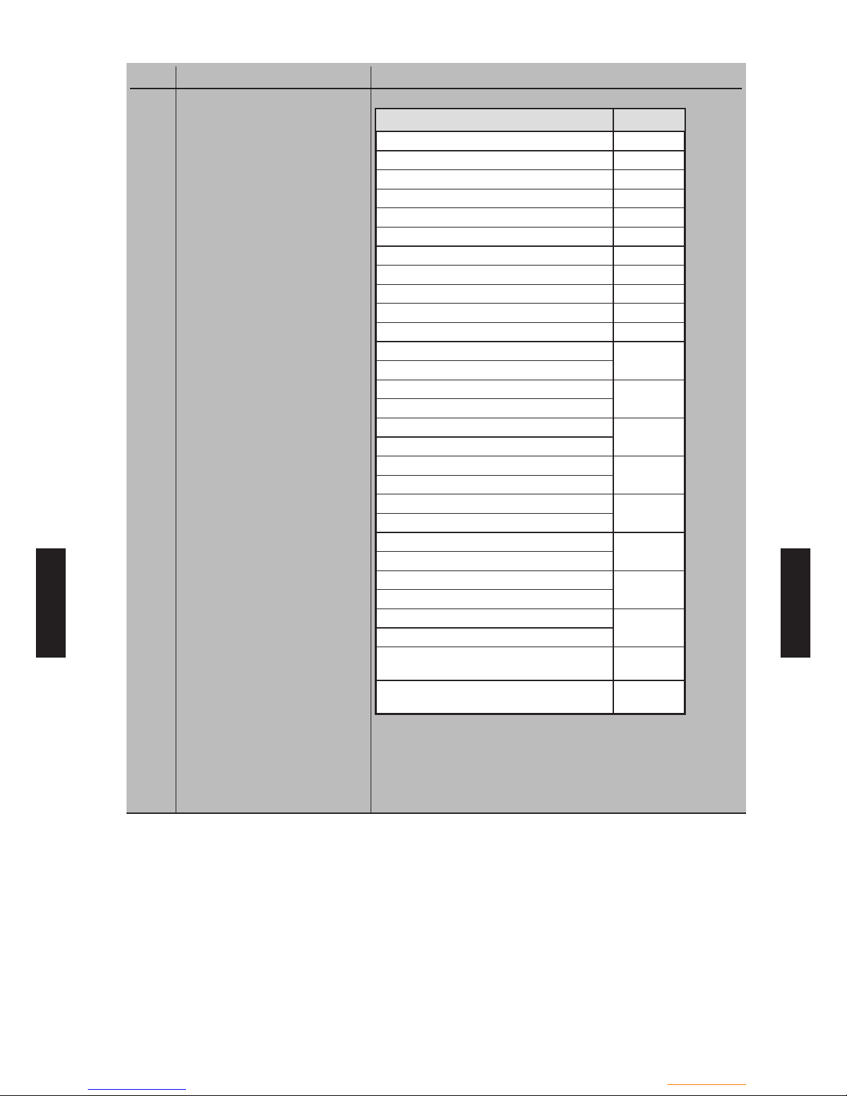
- (CS01 - 04) -
Control system
- (CS01 - 04) -
CONTROL
SYSTEM
CONTROL
SYSTEM
Ref 3 Functions - Denitions
6 Information display Various data.
-
Designation Line
Floor drying current setpoint Current drying day Terminated drying days State heat pump 8006
State supplementary source 8022
State DHW 8003
State swimming pool 8011
State heating circuit 1 8000
State heating circuit 2 8001
State cooling circuit 1 8004
Outside temp 8700
Room temp 1
8740
Room setpoint 1
Flow temp 1
8743
Flow temp setpoint 1
Room temp 2
8770
Room setpoint 2
Flow temp 2
8773
Flow temp setpoint 2
DHW (domestic hot water)temp
8830
DHW temp setpoint
Return temp HP
8410
Setpoint (return) HP
Flow temp HP
8412
Setpoint (ow) HP
Swimming pool temp
8900
Swimming pool temp setpoint
Minimum remaining stop time for
compressor 1
-
Minimum remaining running time for
compressor 1
-
Note:
Ensure that the general electrical power supply has been cut
off before starting any repair work.
When the HP is not under tension, protection frost-free is not
assured.

- (CS01 - 05) -
Control system
- (CS01 - 05) -
CONTROL
SYSTEM
CONTROL
SYSTEM
Ref 3 Functions - Denitions
- Reading error codes
Hydraulic unit : Fault visible on the digital display.
Error
number
Error contents Error location
Heat pump operation
despite the error
- No connection Failure to comply with
room thermostat's
polarity
No
10 Outdoor sensor X86 Yes with OT = 0 °C
33 Flow sensor HP X70 Yes
44 Return sensor HP X70 Yes
50 DHW sensor X84 Yes
60 Room sensor 1 Yes
65 Room sensor 2 Yes
105 Maintenance message Yes
121 Flow temp HC1 not reached Yes
122 Flow temp HC2 not reached Yes
127 Anti-legionella temp not reached Yes
369 External fault (safety component) No
370 Outdoor unit error See the next page No

- (CS01 - 06) -
Control system
- (CS01 - 06) -
CONTROL
SYSTEM
CONTROL
SYSTEM
Ref 3 Functions - Denitions
Hydraulic unit : Flashing of the LED visible on the interface card.
LED display
Error contents
LED 2 (green) LED 1 (red)
1 Flash 1 Flash Communication error between Hydraulic unit and Outdoor unit.
2 Flashes 3 Flashes Connection forbidden (series error).
3 Flashes 1 Flash Indoor unit power supply abnormal.
3 Flashes 2 Flashes Serial communication error between Controller /Interface PCBs.
4 Flashes 1 Flash Heat pump capacity signal error (Open or short).
4 Flashes 2 Flashes Hydraulic unit heat-exchange thermister error.
6 Flashes 1 Flash Outdoor unit power supply abnormal.
6 Flashes 2 Flashes Outdoor unit main PCB error.
6 Flashes 3 Flashes Inverter error.
6 Flashes 4 Flashes Active lter error.
6 Flashes 5 Flashes Outdoor unit IPM error.
6 Flashes 7 Flashes Outdoor unit power short interruption error (protective operation).
6 Flashes 8 Flashes Outdoor unit magnetic relay error.
7 Flashes 1 Flash Discharge thermister error.
7 Flashes 2 Flashes Compressor thermister error.
7 Flashes 3 Flashes Heat-exchange thermistor (outlet / intermediate) error.
7 Flashes 4 Flashes Outdoor thermistor error.
7 Flashes 7 Flashes Outdoor unit heat sink temp. thermistor error.
7 Flashes 8 Flashes Expansion valve thermistor error.
8 Flashes 4 Flashes Current sensor error.
8 Flashes 6 Flashes Pressure sensor error / Pressure switch error.
9 Flashes 4 Flashes Current trip.
9 Flashes 5 Flashes Detection of compressor position error. / Compressor start up error.
9 Flashes 7 Flashes Outdoor unit fan motor 1 error.
9 Flashes 8 Flashes Outdoor unit fan motor 2 error.
10 Flashes 1 Flash Discharge temperature protection.
10 Flashes 3 Flashes Compressor temperature protection.
10 Flashes 4 Flashes Outdoor unit pressure error.
10 Flashes 5 Flashes Low pressure abnormal.
10 Flashes 9 Flashes Current overload error.
Continuous ashing (1 sec On / 1
sec Off)
Pump down operation.
Continuous
lighting
Off Defrosting.
- Information concerning maintenance, special mode.

- (CS01 - 07) -
Control system
- (CS01 - 07) -
CONTROL
SYSTEM
CONTROL
SYSTEM
Ref 3 Functions - Denitions
Outdoor unit :
To access the electronic board, you must remove the front (right-hand) facing
from the outdoor unit. Faults are coded by LED ashes.
SW1 SW2 SW3 SW4 SW5
(1)
(2)
(3)
(4)
(5)
Diodes
and switches
SW2
SW3 SW4 SW5
(1)
(2)
(3)
(4)
Terminal
block
Location of switches and LED on outdoor unit
(High power series_Single phase model) (High power series_3-phase model)
When an error occurs :
- Check that the "ERROR (2)" LED blinks, and then "short-press" the [ENTER (SW3)] switch
once.
- The "POWER MODE (1)" LED will blink twice and the "ERROR (2)" LED will blink several time
(see below).
LED display Error contents
1 Flash Serial forward transfer error.
2 Flashes Discharge thermistor error.
3 Flashes Pressure sensor error.
4 Flashes Heat-exchange thermistor (outlet) error.
5 Flashes Heat-exchange thermistor (intermediate) error.
6 Flashes Expansion valve thermistor error.
7 Flashes Outdoor temperature thermistor error.
8 Flashes Compressor thermistor error.
9 Flashes Heatsink thermistor error.
10 Flashes ―
11 Flashes Discharge temperature protection (permanent stoppage).
12 Flashes Compressor temperature protection (permanent stoppage).
13 Flashes Current trip (permanent stoppage).
14 Flashes Detection of compressor position error (permanent stoppage).
15 Flashes Compressor start up error (permanent stoppage).
16 Flashes Fan motor (1) error (permanent stoppage).
17 Flashes Fan motor (2) error (permanent stoppage).
18 Flashes Inverter error.
19 Flashes
Active lter error. (single phase)
P.F.C error. (3-phase)
20 Flashes Low pressure abnormal.
21 Flashes Connection with hydraulic unit error.
22 Flashes Hydraulic unit abnormality condition.

- (CS01 - 08) -
Control system
- (CS01 - 08) -
CONTROL
SYSTEM
CONTROL
SYSTEM
Ref 3 Functions - Denitions
7 Conrm "OK" Input into the selected menu.
-
Conrmation of the parameter settings. Conrmation of the adjustment to the comfort temp. setting. -
8 Selecting cooling mode If the installation is tted with the cooling kit :
-
- Cooling operating according to the heating program
(Summer/Winter mode switchover is automatic).
9 RESET button
(Hold down the "RESET" key for
less than 3 sec).
Reinitialising the parameters and cancelling error messages. -
Do not use during normal operation3
12 Presence key Comfort / Reduced switchover. -

- (CS01 - 09) -
Control system
- (CS01 - 09) -
CONTROL
SYSTEM
CONTROL
SYSTEM
ROOM THERMOSTAT (Optional parts)2-23
°C
Auto
5
10
11
12
Ref 3 Functions - Denitions
5 Selecting heating mode
Auto
- Heating operating according to the heating program
(Summer/Winter mode switchover is automatic).
- Constant comfort temperature.
- Constant reduced temperature.
- Stand-by mode with anti-frost protection
(Provided that the heat pump's electrical power supply is not
interrupted).
10 Digital display Operating control. Readout of the current temperature, of the
heating mode and of any faults .
11 Control knob Adjusting room temperature setpoint. 12 Presence key Comfort / Reduced switchover.
-
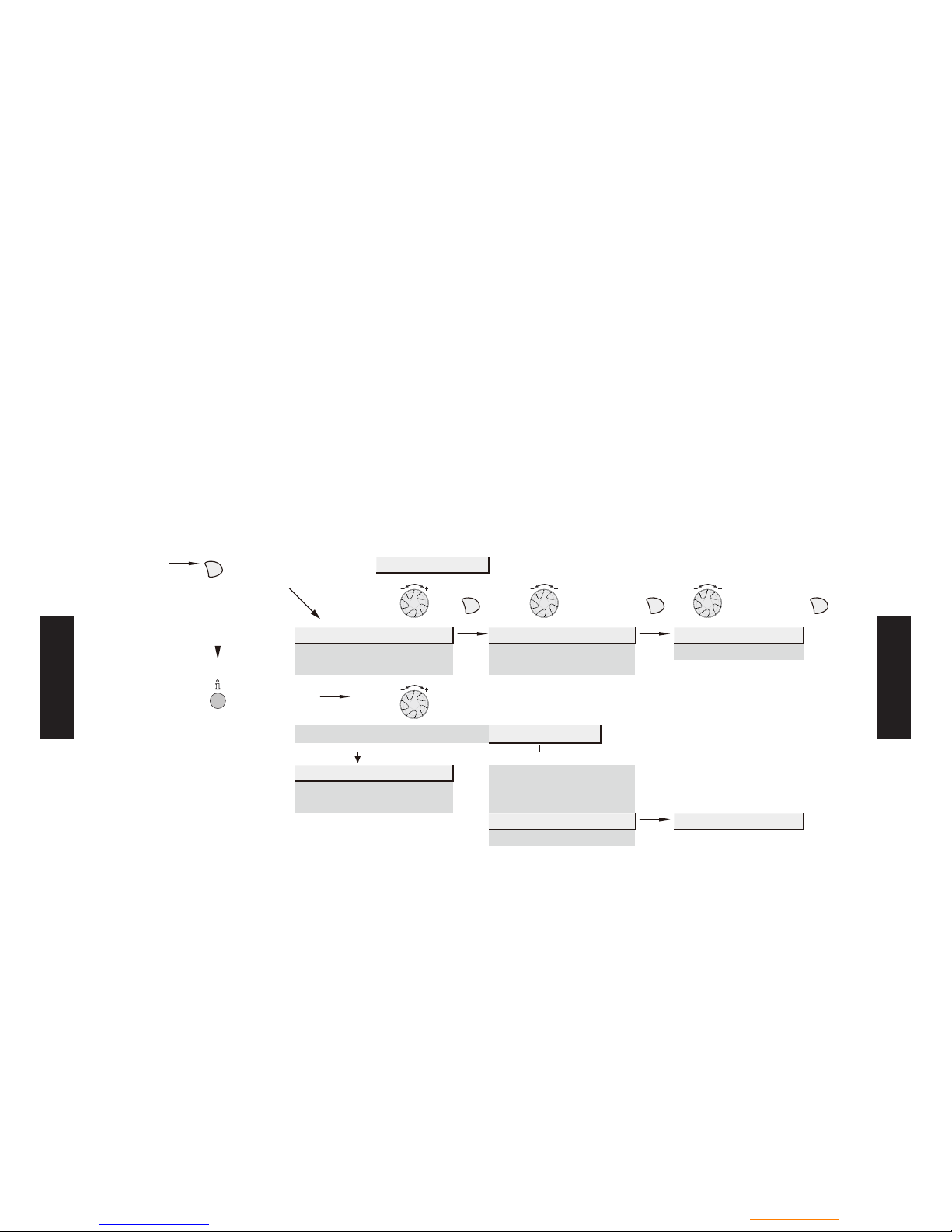
- (CS01 - 10) -
Control system
- (CS01 - 10) -
CONTROL
SYSTEM
CONTROL
SYSTEM
CONTROL SETTING2-33
GENERAL
The settings described below are those which can
be modied by the user.
We wish to remind you that changing the settings
below may cause the heat pump to behave in an
undesirable way. A testing period should be
conducted before the permanent settings of the
heat pump are conrmed. This may require a
number of changes to be made by the installer.
There are 3 access levels:
U: end-user level
I: commissioning level (installer start-up)
S: engineer level (specialist)
SETTING PARAMETERS
-Choose the desired level.
-Scroll the menu list.
-Choose the desired menu.
-Scroll the function lines.
-Choose the desired line.
-Adjust the parameter.
-Check the setting by pressing OK.
-To return the menu, press ESC.
If no setting is made for 8 minutes, the screen returns automatically to the basic display.
Basic
display
OK
Brief press
End user
OKOKOK
Time of day and date Hours / minutes 1 Hours 1...24 h
Operator section Day / month 2 Minutes 0...60 min
Time prg heating circuit 1 Year 3
Press for
3 seconds
End user Commissioning
Engineer
Time of day and date
Hours / minutes 1
Operator section
Day / Month 2
Time prg heating circuit 1 Year 3
Start of summertime 4
01.01...31.12
End of summertime 5
- (CS01 - 11) -
Control system
- (CS01 - 11) -
CONTROL
SYSTEM
CONTROL
SYSTEM
FUNCTION TABLE
LINE
ACCESS
LEVEL
FUNCTION
SETTING RANGE
OR DISPLAY
FACTORY
SETTING
Time of day and date
1 U Hours/minutes 00:00…23:59
2 U Day/month 01.01…31.12
3 U Year 1900…2099
5 S Start of summer time (Day / Month) 01.01…31.12 25.03
6 S End of summer time(Day / Month) 01.01…31.12 25.10
The change of hour will appear at 3:00 rst Sunday after the regulated date.
Operator section
20 U Language
English, Français, Italiano,
Nederlands...
English
22 S Info Temporary, Permanent Temporary
26 S Operation lock On, Off Off
27 S Programming lock On, Off Off
28 I Direct setting
Automatic storage,
With conrmation
With
conrmation
29 I Temperature units
Pressure units
°C, °F
bar, psi
°C
bar
44 I Operation HC2 Jointly with HC1
Independently
Jointly with
HC1
46 I Operation HC3/P Jointly with HC1
Independently
Jointly with
HC1
70 S Display software version
Time program heating / cooling, circuit 1
500 U Pre-selection (Day / Week)
Mon-Sun, Mon-Fri, Sat-Sun,
Monday, Tuesday, …
Mon-Sun
501 U 1
st
phase on (start) 00:00…--:-- 06:00
502 U 1
st
phase off (end) 00:00…--:-- 22:00
503 U 2
nd
phase on (start) 00:00…--:-- --:--
504 U 2nd phase off (end) 00:00…--:-- --:--
505 U 3
rd
phase on (start) 00:00…--:-- --:--
506 U 3
rd
phase off (end) 00:00…--:-- --:--
516 U Default values, Circuit 1 No, Yes No
Yes + OK: The default values memorised in the regulator replace and cancel the
customised heating programs.
Your customised settings are therefore lost.
Time program heating / cooling, circuit 2
520 U Pre-selection (Day / Week)
Mon-Sun, Mon-Fri, Sat-Sun,
Monday, Tuesday, …
Mon-Sun
521 U 1
st
phase on (start) 00:00…--:-- 06:00
522 U 1st phase off (end) 00:00…--:-- 22:00
523 U 2
nd
phase on (start) 00:00…--:-- --:--
524 U 2
nd
phase off (end) 00:00…--:-- --:--
525 U 3
rd
phase on (start) 00:00…--:-- --:--
526 U 3
rd
phase off (end) 00:00…--:-- --:--
536 U Default values, Circuit 2 No, Yes No
Yes + OK: The default values memorised in the regulator replace and cancel the
customised heating programs.
Your customised settings are therefore lost.
- (CS01 - 12) -
Control system
- (CS01 - 12) -
CONTROL
SYSTEM
CONTROL
SYSTEM
LINE
ACCESS
LEVEL
FUNCTION
SETTING RANGE
OR DISPLAY
FACTORY
SETTING
Time program 4 / DHW
560 U Pre-selection (Day / Week)
Mon-Sun, Mon-Fri, Sat-Sun,
Monday, Tuesday, …
Mon-Sun
561 U 1
st
phase on (start) 00:00…--:-- 00:00
562 U 1
st
phase off (end) 00:00…--:-- 05:00
563 U 2nd phase on (start) 00:00…--:-- 14:30
564 U 2
nd
phase off (end) 00:00…--:-- 17: 0 0
565 U 3
rd
phase on (start) 00:00…--:-- --:--
566 U 3
rd
phase off (end) 00:00…--:-- --:--
576 U Default values, Circuit 2 No, Yes No
Yes + OK: The default values memorised in the regulator replace and cancel the
customised heating programs.
Your customised settings are therefore lost.
Holidays heating circuit 1
641 U Preselection Period 1…8 Period 1
642 U Period start (Day / Month) 01.01…31.12 --:--
643 U Period end (Day / Month) 01.01…31.12 --:--
648 U Operating level Frost protection,
Reduced
Frost
protection
Holidays heating circuit 2
651 U Preselection Period 1…8 Period 1
652 U Period start (Day / Month) --:--, 01.01…31.12 --:--
653 U Period end (Day / Month) --:--, 01.01…31.12 --:--
658 U Operating level Frost protection,
Reduced
Frost
protection
Heating circuit 1
710 U Comfort setpoint
Reduced setpoint…
Comfort setpoint maximum
20°C
712 U Reduced setpoint
Frost protection setpoint…
Comfort setpoint
19°C
714 U Frost protection setpoint 4 °C… Reduced setpoint 8°C
716 S Comfort setpoint maximum 20…35°C 28°C
720 I Heating curve slope 0.1... 4 0.5
721 I Off-set of the heating curve -4.5…4.5°C 0°C
730 I Summer / winter heating limits 8…30°C 18°C
When the average of the outside temperatures over the past 24 hours reaches 18°C, the
regulator switches off the heating (as an economy measure). During summer mode, the
display shows "Eco". This function is only active in automatic mode.
740 I Flow temp setpoint min 8 °C... Flow temp
setpoint max
17°C
(with dynamic radiator, adjust from 30 to 35°C)
741 I Flow temp setpoint max Flow temp setpoint min...
70 °C
55°C
Floor heating system = 50 °C / Radiators = 65 °C.
Important Note : Maximum temperature limitation is not a safety function as required by
ground heating.
750 S Room inuence 1...100% 50%
- (CS01 - 13) -
Control system
- (CS01 - 13) -
CONTROL
SYSTEM
CONTROL
SYSTEM
LINE
ACCESS
LEVEL
FUNCTION
SETTING RANGE
OR DISPLAY
FACTORY
SETTING
760 S Room temp limitation 0.5…4°C 0.5°C
As soon as the room temperature = [Setpoint line 710 (ex. 20°C) + Room temperature
limitation setpoint line 760 (ex. 0.5 °C)] > 20.5 °C => The heat pump is stopped.
It restarts when the room temperature falls below the setpoint (in the example, Room
temperature < 20,0 °C).
780 S Quick setback
Off
Down to reduced setpoint
Down to frost prot setpoint
Off
790 S Optimum start control max 0…360min 180 min
791 S Optimum stop control max 0…360min 30 min
800 S Reduced setpoint increase start -30…10°C ---°C
801 S Reduced setpoint increase end -30…10°C -5°C
830 S Mixer valve boost 0…50°C 0°C
834 S Actuator running time 30…873s 240s
850 I Floor curing function
Off
- Off: Early interruption of the current programme, programme inactive.
- Operational heating.
- Heating ready for occupation.
- Operational heating + ready heating.
- Ready heating + operational heating.
- Manual: Manual mode enables you to programme your own concrete slab drying time.
The function ends automatically after 25 days.
851 I Floor curing setpoint manually 0…95°C 25°C
This function enables you to set the custom concrete slab drying temperature. This
temperature remains xed.
The concrete slab-drying programme stops automatically after running for 25 days.
856 I Floor curing day current 0...32
857 I Floor curing days completed 0...32
900 S Operating mode changeover
None, Protection mode,
Reduced, Comfort,
Automatic
Reduced
Operating mode at end of concrete slab drying period.
Cooling circuit 1
901 U Operating mode
Protection, Automatic,
Reduced,Comfort
Protection
902 U Comfort cooling setpoint 1 7…4 0 °C 24°C
903 U Reduced setpoint 5... 40°C 26°C
908 I Flow temp setpoint at OT 25°C 6... 35°C 20°C
909 I Flow temp setpoint at OT 35°C 6... 35°C 16°C
912 I Cooling limit at OT 8... 35°C 24°C
913 S Lock time at end of heating / cooling 8... 100h 24h
918 S Summer compensation start at OT 20…50°C 26°C
919 S Summer compensation end at OT
20…50°C 40°C
920 S Summer compensation setpoint
increase
1... 10 °C 4°C
923 S Flow temp setpoint min OT 25°C 6…35°C 18°C
924 S Flow temp setpoint min OT 35°C 6…35°C 18°C
928 S Room inuence 1…10 0% 80%
932 S Room temp limitation 0,5... 4 °C 0.5°C
938 S Mixing valve decrease 0…20°C 0°C
941 S Actuator running time 30…873s 240s
963 S With primary controller/system pump No, Yes No*
*Basic setting : 1 circuit = No ; 2 circuits = Yes.

- (CS01 - 14) -
Control system
- (CS01 - 14) -
CONTROL
SYSTEM
CONTROL
SYSTEM
LINE
ACCESS
LEVEL
FUNCTION
SETTING RANGE
OR DISPLAY
FACTORY
SETTING
Heating circuit 2
1010 U Comfort setpoint
Reduced setpoint…
Comfort setpoint maximum
20°C
1012 U Reduced setpoint
Frost protection setpoint…
Comfort setpoint
19.0°C
1014 U Frost protection setpoint 4°C… Reduced setpoint 8.0°C
1016 S Comfort setpoint maximum Comfort temp... 35 °C 28.0°C
1020 I Heating curve slope 0.1… 4 0.5
1021 I Off-set of the heating curve -4.5…4.5°C 0°C
1030 I Summer / winter heating limits 8...30 °C 18°C
1040 I Flow temp setpoint min 8…70°C 17°C
1041 I Flow temp setpoint max 8…70°C 55°C
1050 S Room inuence 1...1 00% 50%
1060 S Room temperature limitation 0.5…4°C 0.5°C
As soon as the room temperature = [Setpoint line 1010 (ex. 20°C) + Room temperature
limitation setpoint line 1060 (ex. 0,5 °C)] > 20,5 °C => The heat pump is stopped.
It restarts when the room temperature falls below the setpoint (in the example, Room
temperature < 20,0 °C).
1080 S Quick setback
Off
Down to reduced setpoint
Down to frost prot setpoint
Off
1090 S Optimum start control max 0…360 min 180 min
1091 S Optimum stop control max 0…360 min 30 min
1100 S Reduced setpoint increase start ---, -30…10°C ---°C
1101 S Reduced setpoint increase end ---, -30…10°C -5°C
1130 S Mixer valve boost 0…50°C 0°C
1134 S Actuator running time 30…873sec 240sec
1150 I Floor curing function Off
- Off: Early interruption of the current programme, programme inactive.
- Operational heating.
- Heating ready for occupation.
- Operational heating + ready heating.
- Ready heating + operational heating.
- Manual: Manual mode enables you to programme your own concrete slab drying time.
The function ends automatically after 25 days
1151 I Floor curing setpoint manually
(if line 1150 = manual)
0…95°C 25°C
This function enables you to set the custom concrete slab drying temperature. This
temperature remains xed.
The concrete slab-drying program stops automatically after running for 25 days.
1156 I Floor curing day current 0... 32
1157 I Floor curing day completed
0... 32 0
1200 S Operating mode changeover None, Protection mode,
Reduced, Comfort,
Automatic
Reduced
Domestic hot water
1600 U Operating mode Off, On, Eco On
1610 U Nominal setpoint Reduced setpoint (line
1612)…65 °C
55°C
The backup electrical system is required to reach this level.
1612 U Reduced setting 8 °C...Nominal setting
(line 1610)
40°C

- (CS01 - 15) -
Control system
- (CS01 - 15) -
CONTROL
SYSTEM
CONTROL
SYSTEM
LINE
ACCESS
LEVEL
FUNCTION
SETTING RANGE
OR DISPLAY
FACTORY
SETTING
1620 I Release of DHW load
24h / day
Heating circuit time programme
Programme 4 / DHW
Off- peak tariff (Off-peak)
Programme 4 / DHW
and Off-peak
Programme
4 / DHW
24h / day: The temperature of the DHW is constantly maintained at the DHW comfort
setting.
Heating circuit time programme: The DHW is produced according to the programming
for the ambient temperature (with 1 hour in advance when switched on).
Programme 4 / DHW: The DHW programme is separate form the heating circuit
programme.
Off-peak tariff* : The electrical backup heating is only authorised to operate during the
off-peak period.
T'prog 4/DHW or low-tariff *: The electrical backup heating is authorised to operate
during the comfort period or off peak.
* - Connect the "Power Provider" contact to input EX2. In the case of a day /night contract,
the electric back-ups for the DHW tank are subject to the power supplier's tariffs. Switching
on the electric back-up for the DHW tank is only authorised during off-peak hours.
1640 I Legionella function
Off, Per iodically (depending line
setting 1641), Fixed weekday
(depending line setting 1642)
Off
1641 I Legionella function periodically 1 to 7 7
1642 S Legionella function weekday Monday, Tuesday,... Saturday
1644 S Legionella function time
1645 S Legionella funct setpoint
1646 S Legionella funct duration
1647 S Legionella funct circ pump Off, On Off
1660 S Legionella function weekday
Time program 3/HCP,
DHW release,
Time program 4/DHW,
Time program 5
DHW release
Swimming pool (Only with swimming pool kit option)
2055 U Setpoint solar heating 8... 80 °C 26°C
2056 U Setpoint source heating 8... 35 °C 22°C
2057 S Swi diff source heating 0.5... 3 °C 0.5°C
2065 S Charging priority solar Priority 1, Priority 2,
Priority 3
Priority 1
2080 S Setpoint source heating No, Yes Yes
Heat pump
2803 S Overrun time cond pump 8…240s 240s
2843 S Compressor off time min 0 …12 0m i n 8 m in
2844 S Switch-off temp max 8…1 00 °C 75°C
2862 S Locking time stage 2 / mod 0…40min 5min
2873 S Compressor mod run time 10…600s 240s
2882 S Release integral electric ow 0…500°Cmin 100°Cmin
2884 S Release electric ow below OT
Electrical release - start-up with
outside temperature
-30…30°C 2°C
2916 S Max setpoint HP DHW charg 8… 80°C 58°C
- (CS01 - 16) -
Control system
- (CS01 - 16) -
CONTROL
SYSTEM
CONTROL
SYSTEM
LINE
ACCESS
LEVEL
FUNCTION
SETTING RANGE
OR DISPLAY
FACTORY
SETTING
2920 S With electrical utility lock (EX1) Locked (Blocked on
standby),
Released
Released
Released : HP = ON _ Back-up DHW = off _ 1st back-up HP = off _ 2nd back-up HP = off
_ Boiler = ON
Locked (Blocked on standby) : HP = off _ Back-up DHW = off _ 1st back-up HP = off _
2nd back-up HP = off _ Boiler = ON
Energy meter
3095 S
Not used…
3267 U
Additional generator (Boiler connection)
3692 S With DHW charging
Locked
Substitute
Complement
Instantly
Substitute
- DHW Instantly : When DHW request, the HP and the boiler are put into operation. The
HP will stop when the primary return temperature is over 55 °C.
- DHW Substitute : If the outdoor temperature is above 2 °C, the operation of the HP when
DHW request last 5 minutes at least. The HP operating time can be extended depending
on the outdoor temperature. The boiler will activate then.
3700 S Release below outside temp -50…50°C 2°C
3701 S Release above outside temp -50…50°C --3705 S Overrun time 0...120min 20min
3720 S Switching integral (for boiler relief) 0...500°Cmin 100°Cmin
3723 S Locking time 1...120min 30min
Domestic hot water (DHW)
5024 S Switching differential 0…20°C 7°C
5030 S Charging time limitation 10…600min 90min
5055 S Recooling temp 10…95°C 65°C
5057 S Recooling collector
Off
Summer
Always
Summer
5061 S Electric immersion heater release
24h / day
Release of DHW
Programme 4 / DHW
Release of
DHW
5093 S With solar integration No, Yes Yes
Installation conguration
5700 I Pre-setting 1,2,3,... 9 1
This control enables you to choose one of the 4 pre-selected installation congurations.
The hydraulic layouts for the various congurations are detailed in the section: "Installation
Congurations".
- Pre-setting 1: 1 heating circuit with or without electrical back-up, with DHW tank.
- Pre-setting 2: 2 heating circuits with or without electrical back-up, with DHW tank.
- Pre-setting 3: Boiler connection and 1 heating circuit and DHW tank.
- Pre-setting 4: Boiler connection and 2 heating circuits and DHW tank.
- Pre-setting 5 and more: Not used.
5710 S Heating circuit 1 Off, On On
5711 S Cooling circuit 1
Off
4-pipe system
2-pipe system
Off
Set the parameter to " 2-pipe system cooling " with the cooling kit.
5715 S Heating circuit 2 Off, On On

- (CS01 - 17) -
Control system
- (CS01 - 17) -
CONTROL
SYSTEM
CONTROL
SYSTEM
LINE
ACCESS
LEVEL
FUNCTION
SETTING RANGE
OR DISPLAY
FACTORY
SETTING
5716 S Cooling circuit 2
Off
4-pipe system cooling
2-pipe system cooling
Off
Set the parameter to " 2-pipe system cooling " with the cooling kit.
If the installation consists of 2 heating circuits.
5731 S DHW controlling element Q3
No charging request ¦
Charging pump ¦
Diverting valve
Diverting
valve
5740 S Output el imm heater K6 0,1... 99 kW 2
5806 I Type el imm heater ow
1 : 3-st age
2 : 2-stage excluding
3 : 2-stage complementar y
4 :Modulating UX
3 : 2-stage
complementary
5950 S Function input H1 --5953 S Input value 1 H1 0
5954 S Function value 1 H1 0
5955 S Input value 2 H1 10
5956 S Function value 2 H1 100
5960 S Function input H3 None
5963 S Input value 1 H3 0
5964 S Function value 1 H3 0
5965 S Input value 2 H3 10
5966 S Function value 2 H3 100
5980 S Function input EX1 1
5981 S Contact type input EX1 NC
(Normally-closed contact)
NO
(Normally-opened contact)
NO
5982 S Function input EX2 Low-tariff E5
5983 S Cont type input EX2 NC
(Normally-closed contact)
NO
(Normally-opened contact)
NC
5985 S Cont type input EX3 NC
(Normally-closed contact)
NO
(Normally-opened contact)
NO
6098 S Readjustm collector sensor -20…20°C 0°C
6100 S Readjustment outside sensor -3…3°C 0°C
6117 S Central setp compensation 1...100°C 5°C
6120 S Frost protection plant On, Off On
6201
S Reset sensors No, Yes No
6205 S Reset to default parameters No, Yes No
6220 S Software version (RVS) 0…99 --6300 S Info 1 OEM 0... 65535 --6301 S Info 2 OEM 0... 65535 ---
LPB system
6600 S Device address 0 …16 1
Error
6711 U Reset HP No, Yes No
6800 S History 1 Time, Date, Error code
6802 S History 2 Time, Date, Error code
6804 S History 3 Time, Date, Error code
6806 S History 4 Time, Date, Error code
6808 S History 5 Time, Date, Error code

- (CS01 - 18) -
Control system
- (CS01 - 18) -
CONTROL
SYSTEM
CONTROL
SYSTEM
LINE
ACCESS
LEVEL
FUNCTION
SETTING RANGE
OR DISPLAY
FACTORY
SETTING
6810 S History 6 Time, Date, Error code
6812 S History 7 Time, Date, Error code
6814 S History 8 Time, Date, Error code
6816 S History 9 Time, Date, Error code
6818 S History 10 Time, Date, Error code
Maintenance / special regime
7070 S HP interval ---, 1..240 months ---months
7071 S HP time since maintenance
Reset ? (no, yes)
0...240months 0months
7073 S Cur starts compressor 1/hrs run
Reset ? (no, yes)
0...1 2 0
7141 U Emergency operation Off, On Off
Off: Heat pump functions normally (with boosters if necessary).
On: Heat pump uses the electric boost system or the boiler connection.
Use the “On” position only in Assist mode or Test mode: may result in high power bills.
7142 S Emergency operating function type Manual, Automatic Manual
Manual: Emergency mode is not active when a fault occurs (Emergency mode = OFF).
Automatic: Emergency mode is active when a fault occurs (Emergency mode = ON).
In "Automatic" position, the energy cost can be onerous if the error is not detected and
eliminated.
7150 I Simulation outside temp -50... 50 °C ---
Input / output test
7700 I Relay test No test
7710 I Output UX1 test 0... 100% --7716 I Output UX2 test 0... 100% --7722 I Digital output DO2 Off, On Off
7723 I Heat pump D3 Off, On Off
7724 I Outputs test UX3 ("Inverter"
command)
0... 100% ---
7725 I Voltage value (Ux3) 0... 10 v --7804 I Sensor temperature BX1 (HP ow
temperature)
-28…350°C ---
7805 I Sensor temperature BX2 (HP return
temperature)
-28…350°C ---
7806 I Sensor temperature BX3 (DHW
temperature)
-28…350°C ---
7807 I Sensor temperature BX4 (Outside
temperature)
-28…350°C ---
7858 I Input signal H3
None, Closed (ooo)
Open (-- -)
Pulse
Frequency Hz
Voltage V
None
7911 I Input EX1 (Power shedding, EJP) 0, 230 V --7912 I Input EX2 (Tariffs day/night) 0, 230 V --7913 I Input EX3 (External fault) 0, 230 V ---
State
8000 I State heating circuit 1 --8001 I State heating circuit 2 --8003 I State DHW --8004 I State cooling circuit 1 --8006 I State heat pump ---
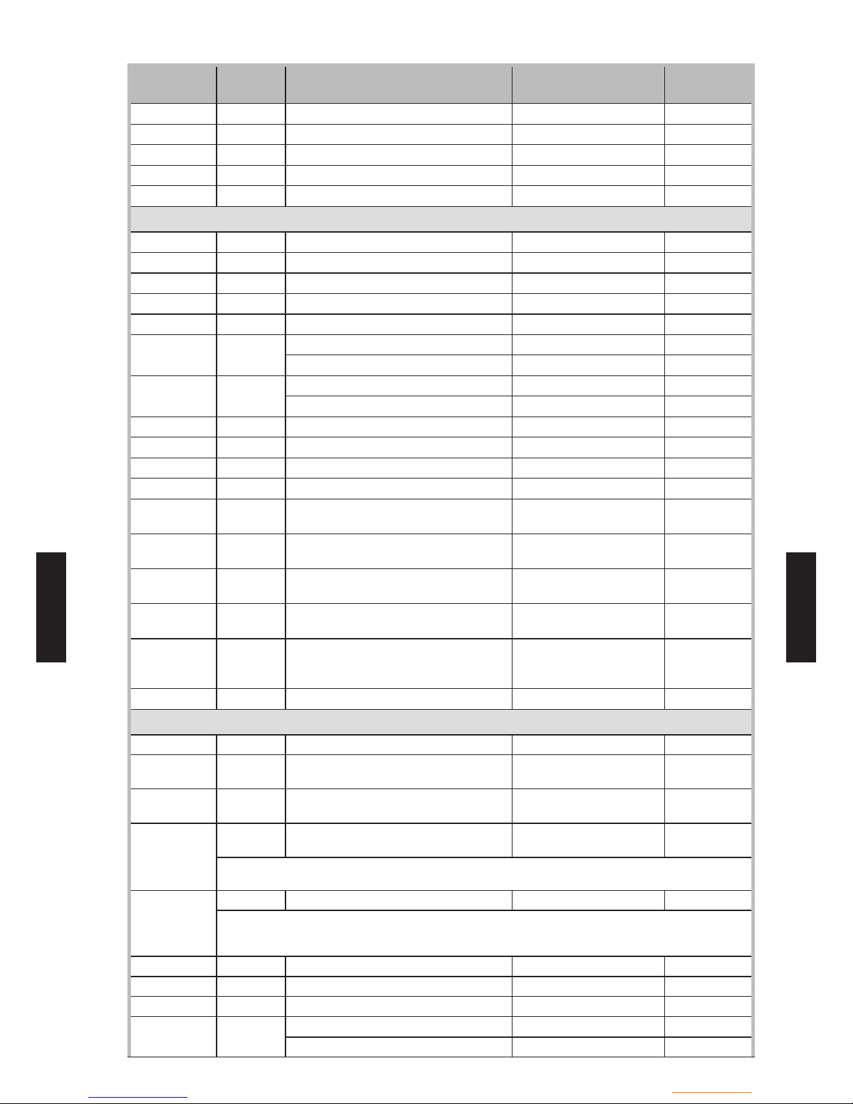
- (CS01 - 19) -
Control system
- (CS01 - 19) -
CONTROL
SYSTEM
CONTROL
SYSTEM
LINE
ACCESS
LEVEL
FUNCTION
SETTING RANGE
OR DISPLAY
FACTORY
SETTING
8007 I State solar --8010 I State buffer --8011 I State swimming pool --8022 I State supplementary source --8025 I State cooling circuit 2 ---
Generator diagnosis
8400 I Compressor 1 Off, On Off
8402 I Electrical resistance ow 1 Off, On Off
8403 I Electrical resistance ow 2 Off, On Off
8406 I Condenser pump Off, On Off
8407 S Speed condenser pump 0…100% ---
8410 U Return temp HP 0... 140 °C ---
Setpoint (ow) HP 0... 140 °C ---
8412 U Flow temp HP 0... 140 °C ---
Setpoint (ow) HP 0... 140 °C --8413 U Compressor modulation 0…100% ---
8414 I Modulation electric ow 0…100% ---
8425 S Temp differential condenser -50…140°C ---
8450 S Hours run compressor 1 00:00 --8454 S Locking time Heat Pump
Reset ? (no, yes)
0…2730h ---
8455 S Counter number of locks HP
Reset ? (no, yes)
0…65535 ---
8456 S Hours run electric ow
Reset ? (no, yes)
0…2730h ---
8457 S Start counter electric ow
Reset ? (no, yes)
0…65535 ---
8458 I State smart grid
Draw disabled
Draw free
Draw wish
Draw forced
Draw free
8460 I Heat pump throughput 0... 65535 l/min ---
Diagnostics consumers
8700 U Outside temp -50…50°C --8701
U Outside temp min
Reset ? (no, yes)
-50…50°C 50°C
8702 U Outside temp max
Reset ? (no, yes)
-50…50°C -50°C
8703 I Outside temp attenuated
Reset ? (no, yes)
-50…50°C ---
This is the average of the outside temperature over a 24-hour period.
This value is used for automatic Summer / Winter switchover (line 730).
8704 I Outside temp composite -50…50°C ---
The mixed outside temperature is a combination of the current outside temperature and the
average outside temperature calculated by the regulator. This value is used for calculating
the initial temperature.
8730 I Heating circuit pump, circuit 1 Off, On Off
8731 I Mixer valve HC1 open Off, On Off
8732 I Mixer valve HC1 closed Off, On Off
8740 U Room temp 1 0... 50 °C
---
Room setting 1 20°C

- (CS01 - 20) -
Control system
- (CS01 - 20) -
CONTROL
SYSTEM
CONTROL
SYSTEM
LINE
ACCESS
LEVEL
FUNCTION
SETTING RANGE
OR DISPLAY
FACTORY
SETTING
8743 U Flow temperature 1 0... 140 °C
---
Flow temperature setpoint 1
---
8749 I Room thermostat 1 No demand, Demand
No demand
8756 U Cooling ow temperature 1 0... 140 °C
---
Cooling ow temperature setpoint 1
--8820 I DHW pump Off, On Off
8821 I Electric immersion heater DHW Off, On Off
8830 U DHW temperature 0... 140 °C ---
DHW temp setpoint 50°C
8832 I DHW temp 2 0... 140 °C --8840 S Hours run DHW pump 0…2730h --8841 S Start counter DHW pump 0... 199999 --8842 S Hours run electric DHW 0…2730h --8843 S Start counter electric DHW
0…65535
---
8950 I Common ow temperature 0... 140 °C ---
Common ow temperature setpoint --8957 I Common ow setpoint refrig 0... 140 °C --9005 I Water pressure 1 -100... 500 bar --9006 I Water pressure 2 -100... 500 bar --9009 I Water pressure 3 -100... 500 bar --9010 I Measurement room temp 1 0...50 °C --9011 I Measurement room temp 2 0...50 °C --9031 I Relay output QX1 Off, On On
9032 I Relay output QX2 Off, On On
9033 I Relay output QX3 Off, On On
9034 I Relay output QX4 Off, On Off
9035 I Relay output QX5 Off, On Off
Description of abbreviations :
HC = Heating circuit
OT = Outside temperature
HP = Heat pump
DHW = Domestic hot water
BXx, EXx, QXx, DOx, UXx, Hx = Terminal number

- (CS01 - 21) -
Control system
- (CS01 - 21) -
CONTROL
SYSTEM
CONTROL
SYSTEM
ADJUSTMENT FUNCTION DETAILS
Time of day and date functions
z
The controller has an annual clock which contains
the time, the day of the week and the date.
In order for the function to operate, the time and
date must be set properly on the clock.
LINE FUNCTION
1 Hours / minutes
2 Day / month
3 Year
5 Start of summertime
6 End of summertime
Note:
Summer time/winter time change
D
ates have been set for changing to summer
time or to winter time. The time changes
automatically from 2am (winter time) to 3am
(summer time) or from 3am (summer time) to
2am (winter time) on the rst Sunday following
the respective date.

- (CS01 - 22) -
Control system
- (CS01 - 22) -
CONTROL
SYSTEM
CONTROL
SYSTEM
Operator section functions
z
LINE FUNCTION
20 Language
22 Info
26 Operation lock
27 Programming lock
28 Direct adjustment
29 Temperature unit
Pressure unit
Info
Temporary •
After pressing the Info key, the information display
returns "predened" basic display after 8
minutes or when pressing the operating mode key.
Permanently •
After pressing the Info key, the information display
returns to "new" basic display after a maximum of
8 minutes. The last selected information value is
shown in the new basic display.
Operation lock
If the operating lock is activated, the following
control elements can no longer be adjusted:
Heating circuit mode, DHW mode, room temp
comfort setpoint (knob), occupancy key.
Programming lock
If the programming lock is activated, the setting
values are displayed but may no longer be
changed.
Temporary suspension of programming:
The programming lock can be temporarily
deactivated at programming level. To do this,
simultaneously press OK and ESC keys for at
least 3 seconds. The temporary suspension of the
programming lock remains in effect until you exit
the programming.
Permanent suspension of programming:
First perform a temporary suspension, then cancel
"Programming lock" on line 27.
Direct adjustment
Storage with conrmation •
Correction of the setpoint with the knob will be
adopted only after pressing OK key.
Automatic storage •
Correction of the setpoint with the knob is adopted
without a particular conrmation (timeout) or by
pressing OK key.
Heating Circuit Assignment
LINE FUNCTION
70 Software version (user interface)
applies only to Remote control C75
*
Software version (user interface)
The display shows the current version of the user
interface.
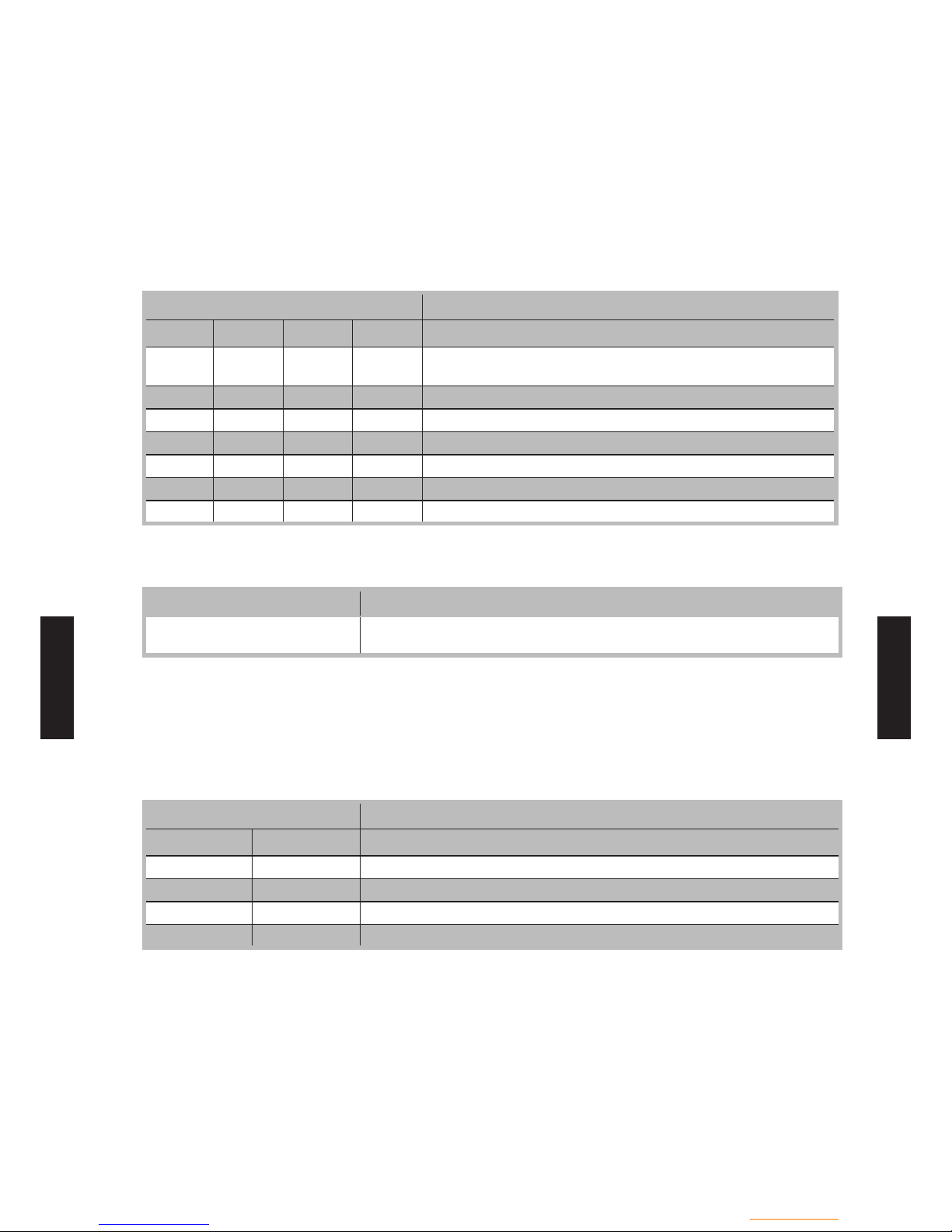
- (CS01 - 23) -
Control system
- (CS01 - 23) -
CONTROL
SYSTEM
CONTROL
SYSTEM
Time program functions (Heating circuit 1 & 2, DHW, Cooling)
z
Several control programs are available for the
heating circuits and the production of DHW. They
are initiated in "Automatic" mode and control the
change in temperature levels (and therefore the
associated setpoints, reduced and comfort) via the
adjusted changeover times.
Enter changeover times:
Changeover times can be adjusted in a combined
way, i.e., identical times for several days or distinct
times for certain days. Preselecting groups of days
(e.g., Mon...Fri and Sat...Sun) having the same
changeover times make adjustment of the
changeover program considerably shorter.
Changeover Points
LINE FUNCTION
HC1 HC2 4/DHW 5
500 520 560 600 Preselection
(Mo- Su / Mo-Fr / Sa – Su / Mo...Su)
501 521 561 601 1st phase on
502 522 562 602 1
st
phase off
503 523 563 603 2nd phase on
504 524 564 604 2
nd
phase off
505 525 565 605 3
rd
phase on
506 526 566 606 3rd phase off
Standard Program
LINE FUNCTION
516, 536, 576, 616 Default values
(No /Yes)
All time programs can be reset to factory settings.
Each time program has its own programming line
for this reset action.
In this case, individual settings will be lost!
Holidays
LINE FUNCTION
HC1 HC2
641 651 Preselection
642 652 Period start (Day / Month)
643 653 Period end (Day / Month)
648 658 Operation level
The holiday program enables changing the heating
c
ircuits over to a selected operating level according
to the date (calendar).
Important:
The holiday program can be used only in the
automatic mode.
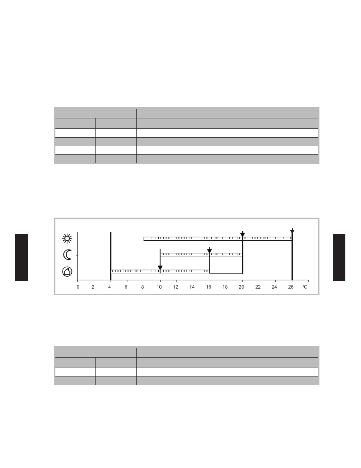
- (CS01 - 24) -
Control system
- (CS01 - 24) -
CONTROL
SYSTEM
CONTROL
SYSTEM
Heating circuit 1 & 2 functions
z
Operating Mode
For heating circuits there are several functions
available which can be individually adjusted for
each heating circuit.
The programming lines for the 2nd heating circuit
are displayed only if the extension module has
been connected to the controller.
Operation of heating circuits 1 and 2 is directly
controlled via the operating mode key.
Setpoint Values
LINE FUNCTION
HC1 HC2
710 1010 Comfort setpoint
712 1012 Reduced setpoint
714 1014 Frost protection setpoint
716 1016 Maximum comfort setpoint
Room temperature:
Room temperature can be set according to different
s
etpoint values. Depending on the selected mode,
these setpoints are activated and provide different
temperature levels in the rooms.
The ranges of congurable setpoints are dened
by their interdependencies, as shown in the graph
below.
Comfort setpoint
Comfort setpoint max
Reduced setpoint
Frost prot3 setpoint
Frost protection:
The protection mode automatically prevents an
e
xcessively sharp drop in room temperature.
In this case the control adopts the frost protection
room setpoint.
Heating Curve
LINE FUNCTION
HC1 HC2
720 1020 Heating curve slope
721 1021 Heating curve displacement
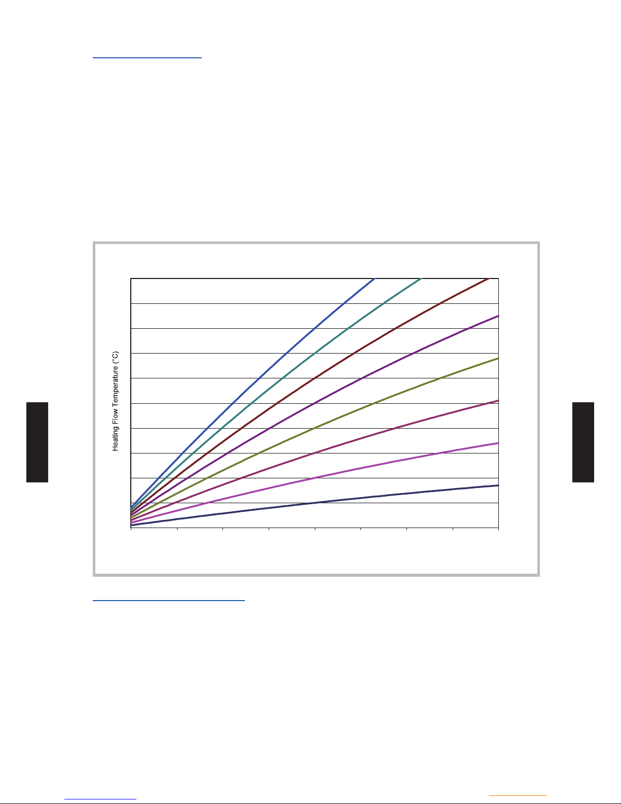
- (CS01 - 25) -
Control system
- (CS01 - 25) -
CONTROL
SYSTEM
CONTROL
SYSTEM
Heating curve slope
Based on the heating characteristic, the controller
computes the ow temperature setpoint which will
be used for controlling the ow temperature in
consideration of atmospheric conditions. Different
settings can be used to adapt the heating
characteristic so that the heating capacity, and
therefore the room temperature, will match the
individual needs.
The colder the outdoor temperature, the greater the
extent to which the slope will modify the ow
temperature. In other words, the slope should be
corrected if the room temperature shows a
difference when the outdoor temperature is low, but
not when it is high.
Increase the setting: -
The ow temperature is increased mainly when
the outdoor temperatures are low.
Decrease the setting: -
The ow temperature is lowered mainly when the
outdoor temperatures are low.
Warning:
The heating curve is adjusted in relation to a room
temperature setpoint of 20°C. If the room
temperature setpoint is modied, the ow
temperature setpoint is automatically recomputed.
This will not modify the setting and amounts to
automatically adapting the curve.
20
30
40
50
60
70
-20,0-15,0-10,0-5,00,05,010,015,020,0
Outdoor Temperature (°C)
0,25
0,5
0,75
1
1,25
1,5
1,75
2
Heating Curves
Heating curve displacement
The curve displacement (offset) modies the ow
temperature in a general and even manner over the
full range of outdoor temperature. In other words,
the displacement should be corrected when the
room temperature is generally too high or too low.

- (CS01 - 26) -
Control system
- (CS01 - 26) -
CONTROL
SYSTEM
CONTROL
SYSTEM
Eco Functions
LINE FUNCTION
HC1 HC2
730 1030 Summer/winter heating limit
Summer/winter heating limit
The summer/winter heating limit switches the
heating on or off through the year according to the
temperature ratio. Changeover is performed
automatically when in automatic mode and thus
avoids the user having to turn the heating on or off.
Changing the input value makes the respective
annual periods (summer/winter) shorter or longer.
If the value is increased: -
Changing to winter operating mode is advanced,
changing to summer mode is delayed.
If the value is decreased: -
Changing to winter mode is delayed; changing to
summer mode is advanced.
Information:
This function does not work in "Continuous comfort
temperature" mode. (Sunlight)
The controller displays "ECO".
The outdoor temperature is attenuated to take the
building's dynamics into account.
Example:
Attenuated outdoor T
Sum/win heating limit + 1°C
Sum/win heating limit
Sum/win heating limit - 1°C
Days
ON
OFF
Flow temperature setpoint
LINE FUNCTION
HC1 HC2
740 1040 Flow temp setpoint min (for fan convectors)
741 1041 Flow temp setpoint max
This limitation allows to dene a range for the
ow temperature setpoint. When ow temperature
setpoint demanded by the heating circuit reaches
the threshold, the setpoint remains permanently at
the maximum or minimum, even if the heat demand
continues to increase or decrease.
Example (line 741 and 1041):
Floor heating system = 50 °C
Higher temperature radiator = 65 °C

- (CS01 - 27) -
Control system
- (CS01 - 27) -
CONTROL
SYSTEM
CONTROL
SYSTEM
Room Inuence
LINE FUNCTION
HC1 HC2
750 1050 Room inuence
Control types:
When using a room temperature sensor there are 3
d
ifferent types of control to choose from.
SETTING CONTROL TYPE
- - - % Simple control according to outdoor conditions *
1...99 % Control according to outdoor conditions with room inuence *
100 % Control according to room temperature only
Requires the connection of an outdoor sensor
*
Simple control according to outdoor
conditions
The ow temperature is computed via the heating
curve according to the composite outdoor
temperature. This type of control requires proper
adjustment of the heating curve, as the control
does not take the room temperature into account
for this adjustment.
Control according to outdoor
conditions with room inuence
The difference between the room temperature and
the setpoint value is measured and taken into
account for temperature control. This enables
taking into account possible heat inputs and
ensures a more accurate room temperature control.
The inuence of the difference is dened as a
percentage. The better the installation in the
reference room (accurate room temperature,
correct installation location, etc.) the higher will be
the value that can be set.
Example:
Approx 60%: the reference room is appropriate
Approx 20%: the reference room is inappropriate
Information:
Activation of the function requires taking into
account the following requirements:
A room sensor must be connected. The "room inuence" parameter must be set between 1 and 99.
The reference room (where the room sensor is installed) must not contain adjusted thermostatic
valves. If present in the room, these valves must
be fully open.
Control according to
room temperature only
The ow temperature is adjusted according to the
room temperature setpoint, the current room
temperature and its evolution. A slight increase in
room temperature, for example, causes an
immediate drop in the ow temperature.
Information:
Activation of the function requires taking into
account the following requirements:
A room sensor must be connected. The "room inuence" parameter must be set -
to 100%.
The reference room (where the room sensor is
installed) must not contain adjusted thermostatic
valves. If present in the room, these valves must be
fully open.
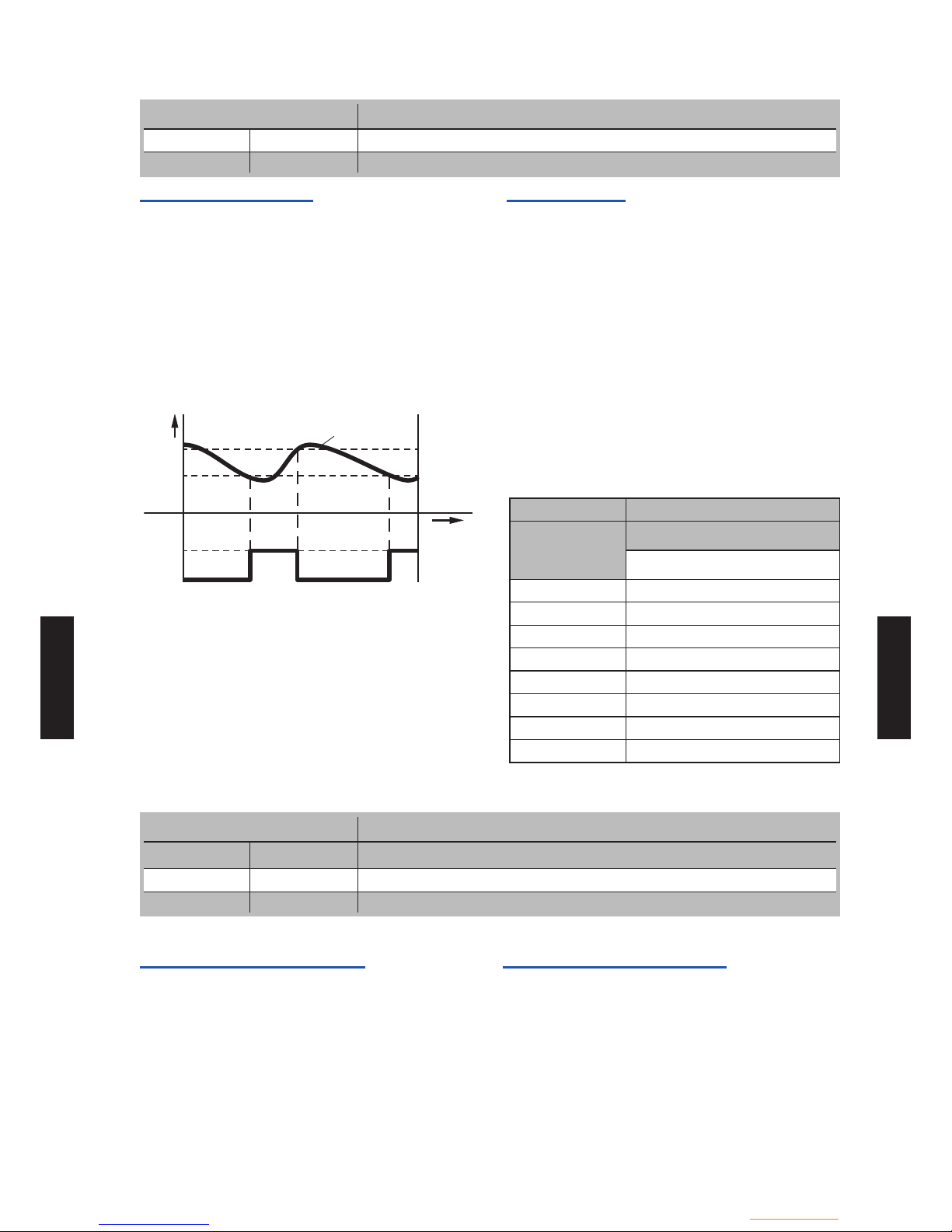
- (CS01 - 28) -
Control system
- (CS01 - 28) -
CONTROL
SYSTEM
CONTROL
SYSTEM
Quick setback
LINE FUNCTION
760 1060 Room temp limitation
780 1080 Quick setback
Room temp limitaion
The "Room temperature limitation" function enables
the heating circuit pump to be deactivated should
the room temperature exceed the current room
temperature setpoint by more than the adjusted
differential.
The heating circuit pump is activated again as soon
as the room temperature falls to a level below the
current room temperature setpoint.
During the time the "Room temperature limitation"
function is active, no heat request is sent to the
producer.
Quick setback
During quick setback, the heating circuit pump is
deactivated and, in the case of mixing circuits, the
mixing valve is fully closed.
When using a room sensor, the function keeps the
heating off until the room temperature drops to the
level of the "Reduced" or "Frost protection" setpoint.
If the room temperature falls to the reduced or frost
level, the heating circuit pump is activated and the
mixing valve released.
Quick setback switches the heating off for a certain
period of time, depending on the outside
temperature
and the building time constant.
Duration of quick setback when "Comfort" setpoint
minus "Reduced" setpoint = 2 K (e.g. "Comfort"
setpoint = 20 °C and "Reduced" setpoint = 18 °C)
°C
TRx
TRw+SDR
TRw
T
ON
P
OFF
TRx : Actual value of room temperature
TRw : Room temperature setpoint
SDR : Room switching differential
P : Pump
T : Time
Building time constant [h]
Composite
outside
temperature
5
Duration of quick setback [h]
15°C 7.7
10°C 3.3
5°C 2.1
0°C 1.6
-5°C 1.3
-10°C 1.0
-15°C 0.9
-20°C 0.8
Optimisation at switch-on and switch-off
LINE FUNCTION
HC1 HC2
790 1090 Optimum start control max
791 1091 Optimum stop control max
Optimum start control max
The change in temperature levels is optimised in
such a way as to reach the comfort setpoint during
changeover times.
Optimum stop control max
The change in temperature levels is optimised in
such a way as to reach the comfort setpoint -1/4 °C
during changeover times.

- (CS01 - 29) -
Control system
- (CS01 - 29) -
CONTROL
SYSTEM
CONTROL
SYSTEM
Reduced Setpoint Increase
LINE FUNCTION
HC1 HC2
800 1100 Reduced setpoint increase start
801 1101 Reduced setpoint increase end
This function is used mainly in heating installations
that do not have high supplies of power (e.g. low
power use homes). When outdoor temperatures are
low, adjusting the temperature would take too long.
Increasing the reduced setpoint prevents excessive
cooling of the rooms in order to shorten the
temperature adjustment period when changing over
to the comfort setpoint.
Comfort
setpoint(710)
Start
increase(800)
End increase
(801)
Composite OT
Reduced
setpoint(712)
Mixing Valve Control
LINE FUNCTION
HC1 HC2
830 1130 Mixer valve boost
834 1134 Actuator running time
Mixer valve boost
The controller adds the increase set here to the
current ow setpoint and uses the result as the
temperature setpoint for the heat generator.
Actuator running time
For the 3-position servomotor, the travel time can
be adjusted. With a 2-position servomotor,
the adjusted travel time is inoperative.
Controlled oor drying function
LINE FUNCTION
HC1 HC2
850 1150 Floor curing function
851 1151 Floor curing setpoint manually
856 1156 Floor curing day current
857 1157 Floor curing day completed
This function is used in the controlled drying of oors.
It adjusts the ow temperature to a temperature
prole. Drying is performed by oor heating via the
heating circuit with a mixing valve or with a pump.

- (CS01 - 30) -
Control system
- (CS01 - 30) -
CONTROL
SYSTEM
CONTROL
SYSTEM
Floor curing function
Off •
The function is deactivated.
Heating operational (Fh) •
The rst part of the temperature prole is
automatically completed.
Heating "ready for occupancy" (Bh) •
The second part of the temperature prole is
handled automatically.
Heating "ready for occupancy" / •
Heating operational
The full temperature prole (1st and 2nd part) is
performed automatically.
Manual •
No temperature prole is performed, but the control
is performed according to the "manual controlled
drying setpoint". The function is automatically
terminated after 25 days
Important:
The standards and directions of the building -
contractor must be followed!
This function will not work properly unless -
the installation has been adequately made
(hydraulics, electricity, settings). Otherwise, the
oors to be dried may be damaged!
The function may be prematurely interrupted by -
setting it to Off.
The maximum ow temperature limitation -
remains active.
Heat pump
ow temp
X : Starting day
Days
Bh
Fh
Fh + Bh
Floor curing setpoint manually
The ow temperature setpoint for the "Manually"
controlled oor drying function can be adjusted
respectively for each heating circuit.
Floor curing day current
Displays the current ow temperature setpoint for
the controlled oor drying function.
Floor curing day completed
Displays the current day of the controlled oor
drying function.
Important:
After a power outage, the installation resumes the
controlled drying function as it was when the
outage occurred.
Operating Mode Changeover
LINE FUNCTION
HC1 HC2
900 1200 Operating mode changeover
(None / Frost protecti on mode / Reduced / Comfort / Automatic)
In case of an external changeover via input H2 (on
the extension module only) the operating mode to
which the changeover will be performed must be
previously dened.

- (CS01 - 31) -
Control system
- (CS01 - 31) -
CONTROL
SYSTEM
CONTROL
SYSTEM
Heating Circuit Frost Protection
Informations:
The heating circuit frost protection is continuously
activated (protection mode
) and is not
adjustable.
Heating circuit frost protection in heating mode: -
If the ow temperature is below 5°C, the controller
initiates the production of heat and starts the
heating pumps, regardless of the current heating
mode.
If the ow temperature rises again above 7°C,
the controller waits another 5 minutes, and then
stops the production of heat and the heating
pumps.
Heating circuit frost protection in cooling mode: -
See Cooling mode.

- (CS01 - 32) -
Control system
- (CS01 - 32) -
CONTROL
SYSTEM
CONTROL
SYSTEM
Cooling circuit 1 functions
z
The cooling sequence is automatically started
when the room temperature is higher than the
comfort setpoint in cooling mode (line 902). The
cooling function must be activated (line 901 = Auto)
and is triggered by the programming clock (line
907). The cooling sequence is interrupted as soon
as heating circuit 1 indicates a need for heat or in
the presence of a heat demand signal from a DHW
circuit or other heating circuit (only if cooling is
active).
The controller measures the current room
temperature and compares it with the room
temperature setpoint to compute the ow
temperature setpoint. If the temperature is not low
enough the heat pump is started to provide cooling
(reversed control of the mixing valve).
The following settings apply to the hydraulic circuit
in zone 1 (HC1). If there is a second zone, this
zone can be cooled with the setting (line 963)
which will connect the pump directly to zone 2. This
will require setting the "Mixing valve sub-cooling"
parameter (line 938) to a suitable value in order for
both zones to be adequately cooled according to
the available emitters.
Warning:
Cooling mode is prohibited on all radiators, heating
only oors, or any emitters not intended for this
purpose.
Operating Mode
LINE FUNCTION
901 Operating mode
(Off / Automatic)
The cooling key on the user interface enables
switching between operating modes.
Off •
The cooling function is deactivated.
Automatic •
The cooling function is automatically activated by
the time program (line 907), the holiday program,
the occupancy key, or according to the need.
Comfort cooling setpoint
LINE FUNCTION
902 Comfort cooling setpoint
In cooling mode the room temperature control
f
ollows the comfort setpoint adjusted under this
setting. The cooling comfort setpoint can be
displayed with a knob on the room unit.
In summer the comfort setpoint is gradually
increased in relation to the outdoor temperature
(see lines 918-920).
Release
LINE FUNCTION
907 Release
(24h/day / Heating circuit time pgm / Time program 5)
The "Release" setting determines the time program
according to which cooling is released.
24h/day •
Cooling is continuously activated (24h/Day).
Time program HC •
Cooling is activated according to the heating circuit
time program.
Time program 5 •
Cooling is released according to time program 5.
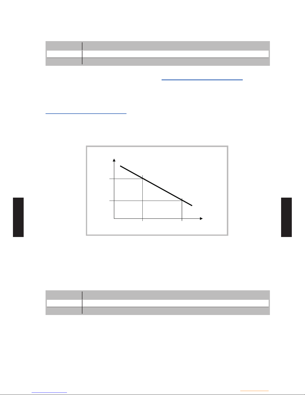
- (CS01 - 33) -
Control system
- (CS01 - 33) -
CONTROL
SYSTEM
CONTROL
SYSTEM
Cooling Characteristic
LINE FUNCTION
908 Flow temp setpoint at OT 25°C
909 Flow temp setpoint at OT 35°C
The controller computes the ow temperature
required for a given composite outdoor temperature
based on the cooling characteristic. This is dened
by two reference points (ow setpoint at 25°C and
at 35°C).
Flow temp setpoint at OT 25°C
This is the cooling ow temperature required when
the composite outdoor temperature is 25°C, without
summer compensation.
Flow temp setpoint at OT 35°C
This is the cooling ow temperature required when
the composite outdoor temperature is 35°C, without
summer compensation.
25°C 35°C
909
908
Flow temp
setpoint
Composite
OT
The cooling characteristic is adjusted for a 25°C
room temperature setpoint. If the room temperature
setpoint is changed the curve will automatically
adapt.
Eco
LINE FUNCTION
912 Cooling limit at OT
913 Lock time at end of heating

- (CS01 - 34) -
Control system
- (CS01 - 34) -
CONTROL
SYSTEM
CONTROL
SYSTEM
Cooling limit at OT
If the composite outdoor temperature is higher than
the cooling limit, cooling is released. If the
composite outdoor temperature falls at least 0.5°C
below the cooling limit, cooling is locked.
Lock time at end of heating
To avoid a quick start of cooling after termination of
heating, the cooling function is locked for a time
period which can be adjusted with this setting.
The lock time starts when there is no valid heating
demand from heating circuit 1. Heating demands
from heating circuits 2 or P are ignored.
Information:
Switching off and switching on again the mode
selection key causes the lock time to be interrupted.
Summer Compensation
LINE FUNCTION
918 Summer compensation start at OT
919 Summer compensation end at OT
920 Summer compensation setpoint increase
In summer the "cooling comfort setpoint" (line 902)
is gradually increased according to the outdoor
temperature. This saves on cooling power and
prevents the differences between the ambient
temperature of the room and the outdoor
temperature being too high.
The resulting "room temperature setpoint" can be
viewed in the Info section.
Summer compensation start at OT
Summer compensation starts to be active from the
outdoor temperature dened here. If the outdoor
temperature continues to rise, the comfort setpoint
will be gradually increased.
Summer compensation end at OT
At this outdoor temperature the summer
compensation reaches its peak efciency (line
920). If the outdoor temperature continues to rise, it
will no longer inuence the comfort setpoint.
Summer compensation setpoint
increase
This setting denes the highest value to which the
comfort setpoint can be increased.
918
919
902
920
Comfort
setpoint
OT
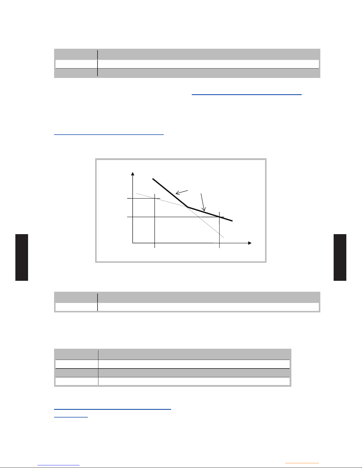
- (CS01 - 35) -
Control system
- (CS01 - 35) -
CONTROL
SYSTEM
CONTROL
SYSTEM
Flow Setpoint Limitation
LINE FUNCTION
923 Flow temp setpoint min at OT 25°C
924 Flow temp setpoint min at OT 35°C
It is possible to assign a lower limit to the cooling
ow temperature.
The limitation line will be dened by two reference
points. In addition the resulting ow setpoint will
have a lowerlimit and may not be less than 5 °C.
Flow temp setpoint min at OT 25°C
Determines the lowest ow temperature for a
composite outdoor temperature of 25°C.
Flow temp setpoint min at OT 35°C
Determines the lowest ow temperature for a
composite outdoor temperature of 35°C.
Warning:
If no outdoor temperature is available, the controller
will use the "Min. ow setpoint at OT= 35°C"
parameter.
C°53 C°52
924
923
Flow temp
setpoint
Flow temp
setpoint
Composite
OT
Room Inuence
LINE FUNCTION
928 Room inuence
When using a room temperature sensor there are 3
d
ifferent types of control to choose from.
SETTING CONTROL TYPE
- - - % Simple control according to outdoor conditions *
1...99 % Control according to outdoor conditions with room inuence *
100 % Control according to room temperature only
Requires the connection of an outdoor sensor
*
Simple control according to outdoor
conditions
The ow temperature is obtained from the
composite outdoor temperature on the basis of the
cooling characteristic.
This type of control requires the cooling curve to be
properly adjusted, as the control does not take the
room temperature into account for this adjustment.

- (CS01 - 36) -
Control system
- (CS01 - 36) -
CONTROL
SYSTEM
CONTROL
SYSTEM
Control according to outdoor conditions
with room inuence
The difference between the room temperature and
the setpoint value is measured and taken into
account for temperature control. This enables
taking into account possible heat inputs and
ensures a more accurate room temperature control.
Thus the differences with the room temperature
are taken into account and the room temperature
becomes more stable. The inuence of the
difference is dened as a percentage.
The better the installation in the reference room
(accurate room temperature, correct installation
location, etc.) the higher will be the value that can
be set.
Example:
Approx 60%: the reference room is appropriate Approx 20%: the reference room is inappropriate -
Activation of the function requires taking into
account the following requirements:
A room sensor must imperatively be connected. The "room inuence" parameter must be set between 1 and 99.
The reference room (where the room sensor is installed) must not contain adjusted thermostatic
valves. Any thermostatic valves present in the
rooms must be fully open.
Control according to room temperature only
The ow temperature is adjusted according to the
room temperature setpoint, the current room
temperature and its evolution. A slight increase in
room temperature, for example, causes an
immediate drop in the ow temperature.
Activation of the function requires taking into
account the following requirements:
A room sensor must imperatively be connected. The "room inuence" parameter must be set to 100%.
The reference room (where the room sensor is installed) must not contain adjusted thermostatic
valves. Any thermostatic valves present in the
rooms must be fully open.
Room Temperature Limitation
LINE FUNCTION
932 Room temperature limitation
The "room temperature limitation" function enables
shutting off the cooling circuit pump if the room
temperature falls below the adjusted room
temperature setpoint (with summer compensation
line 920) by more than the adjusted differential.
The cooling circuit pump is reinitiated as soon as
the room temperature rises again above the current
room temperature setpoint.
If the room temperature limitation function is
active, no cooling demand will be transmitted to
production.
The function is deactivated if:
no room temperature sensor is available -
"Room inuence limit." = --- "Room inuence" (line 928) = --- (simple control -
according to outdoor conditions)

- (CS01 - 37) -
Control system
- (CS01 - 37) -
CONTROL
SYSTEM
CONTROL
SYSTEM
Mixing Valve Control
LINE FUNCTION
938 Mixing valve decrease
941 Actuator running time
945 Mixing valve in heating mode
Mixing valve decrease
The cooling demand issued by cooling circuit 1 to
production is reduced by the adjusted value.
If there is a second zone, this reduction should
enable the second zone to be cooled. To achieve
this result, the sub-cooling must be determined in
accordance with the type of emitter and "With
primary controller/system pump" (line 963) must be
set to "yes" to switch on the pump for the second
zone.
Example:
Conguration How the conguration affects control
Zone 1: Heating/
cooling
oor
Zone 2: Fan coils
938 = 10°C,
with 924 = 18°C
963 = yes
with a 35°C outdoor temperature the ow
setpoint will be 18°C – 10°C i.e. 8°C
while in the rst zone (HCF) it will be 18°C
through action of the mixing valve
Zone 1: Heating/
cooling
oor
Zone 2: HCF
938 = 0°C,
with 924 = 18°C
963 = yes
with a 35°C outdoor temperature the ow
setpoint will be 18°C in both zones
Warning:
If these settings are not chosen properly the heat
pump may stop automatically due to the ow
temperature being too low. A safety mechanism is
triggered at 6°C to protect the exchanger from
freezing.
Actuator running time
For the 3-position servomotor used, it is possible to
adjust the travel time. With a 2-position servomotor,
the adjusted travel time is inoperative.
Mixing valve heating mode
Determines the position of mixing valve 1 during
heating operation is activated.
This parameter is inoperative in installations where
heating and cooling circuits are hydraulically separate.
Control •
The valve controls in heating and cooling mode.
Open •
The valve controls in cooling mode, and is open in
heating mode.
With primary controller/system pump
LINE FUNCTION
963 With primary controller/system pump
(No / Yes)
This setting species whether the cooling circuit is
s
upplied from the primary controller or from the
primary pump (depending on the installation). It can
also be used to provide cooling to the second zone.
Warning:
In the case of a radiator or any other emitter which
does not support the cooling mode in zone 2, this
setting must remain on "No".
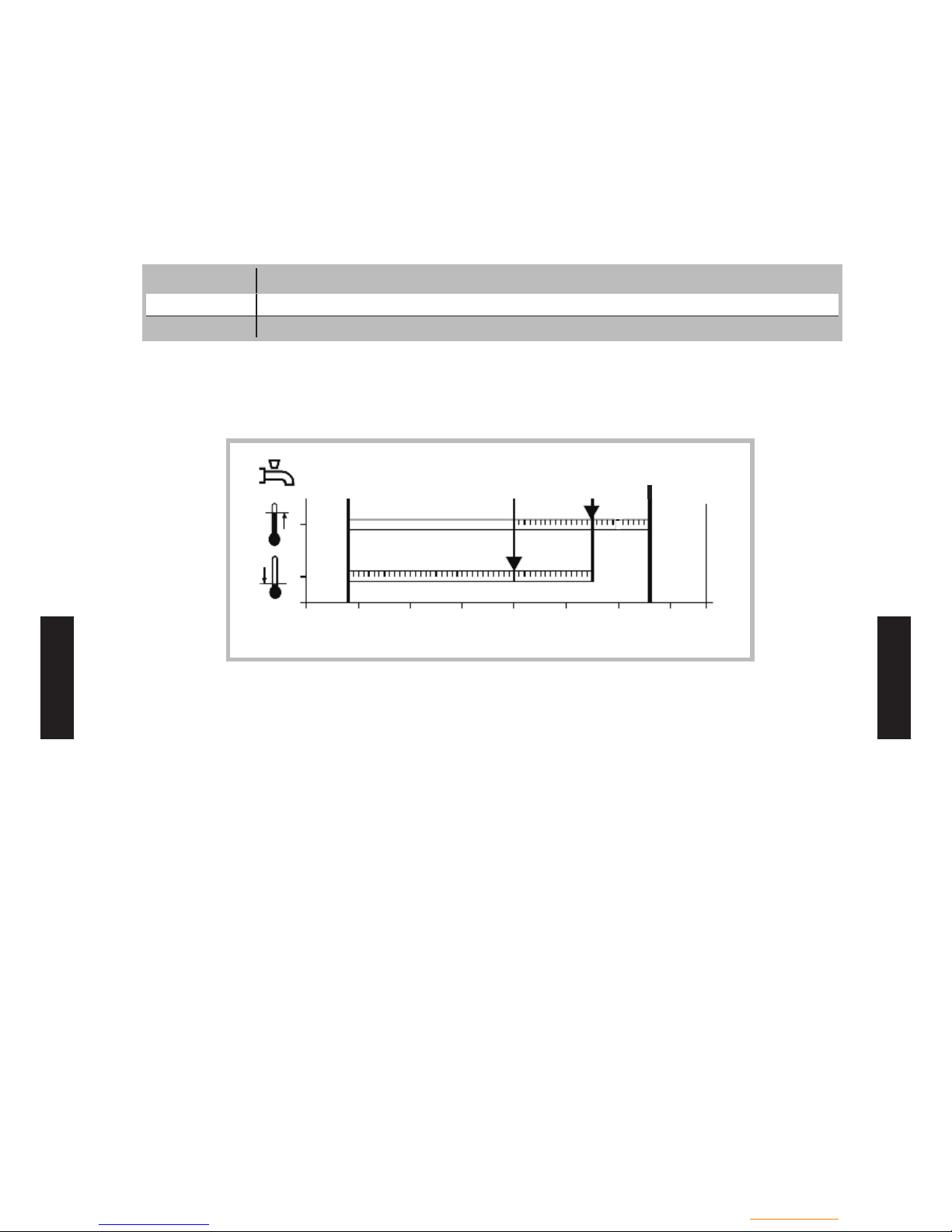
- (CS01 - 38) -
Control system
- (CS01 - 38) -
CONTROL
SYSTEM
CONTROL
SYSTEM
Domestic hot water functions (with DHW kit or with integrated DHW models)
z
The control sets the DHW temperature, according
to the time program or continuously, to the desired
setpoint. The priority of DHW charging over room
heating is adjustable in this case
The controller has a congurable legionella
function designed for protection against legionella
in the storage tank and the pipes. The circulation
pump is controlled according to the current time
program and operating mode.
Setpoint value
LINE FUNCTION
1610 Nominal setpoint
1612 Reduced setpoint
The DHW is heated to various setpoint values.
These setpoints are active according to the selected
operating mode and allow the desired temperatures
to be reached in the DHW storage tank.
Reduced setpoint
Nominal setpoint
DHW max setpoint
0 10 20 30 40 50 60 70
°C
Important:
For optimal operation we recommend reducing the
s
etpoints to the lowest value.
Setpoints which are too high may interfere with
heating and cause some discomfort. In this case
DHW/Heating changeover cycles may successively
occur
If DHW charge boosting is not desired during
the day, we recommend adjusting the reduced
temperature setpoint to 15°C. Full charging will
occur during the night at the nominal temperature..
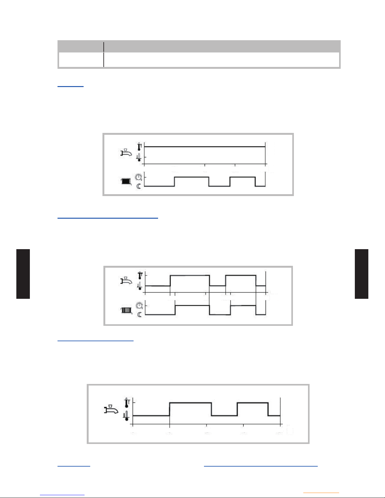
- (CS01 - 39) -
Control system
- (CS01 - 39) -
CONTROL
SYSTEM
CONTROL
SYSTEM
Release
LINE FUNCTION
1620 Release of DHW load
(24h/day / Heating circ time pgm / Time program 4/DHW / Low -tariff/ Time pgm 4/DHW or Low-tarif f)
24h/day
(Not recommended)
Regardless of the time programs, the temperature of
the domestic hot water is continuously maintained at
the DHW nominal setpoint temperature.
Example:
0 6 12 18 24
h
Heating circuit time programs
(Not recommended)
Depending on the heating circuit time programs,
the DHW setpoint is changed between the DHW
temperature nominal setpoint and the DHW
Example:
temperature reduced setpoint. The rst switch-on
point of each phase is advanced by one hour each
time.
0 5 6 12 16 17 24
h
Time program 4 / DHW
(Recommended)
Time program 4 of the local controller is taken into
account for the DHW mode. The changeover
between DHW nominal setpoint and DHW reduced
setpoint occurs on the changeover times of this
program. Thus, domestic hot water charging takes
place independently from the heating circuits.
0 6 12 18 24
h
Low-tariff
Released when the low tariff input is active
(Input EX2)
Time program 4/DHW or low-tariff
Released when DHW program is set to "Nominal"
or if the low tariff input is active.
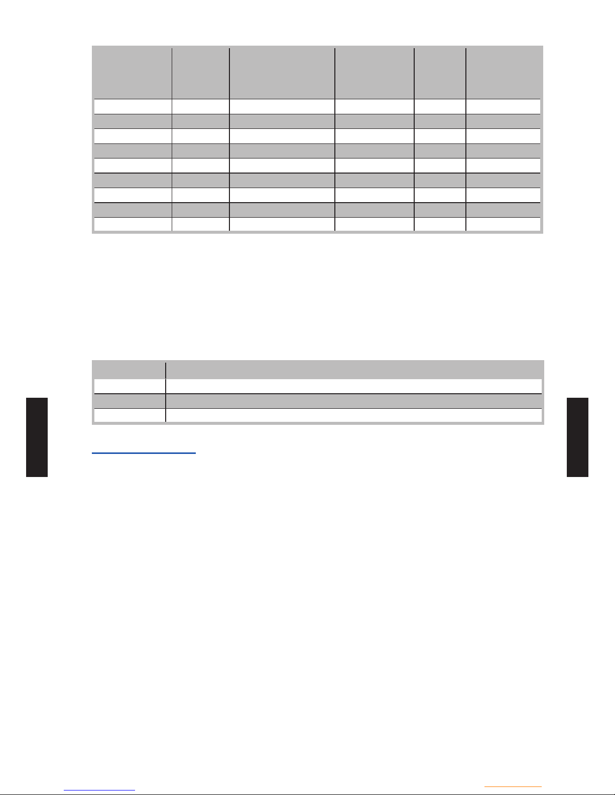
- (CS01 - 40) -
Control system
- (CS01 - 40) -
CONTROL
SYSTEM
CONTROL
SYSTEM
DHW mode
Holiday
status
Release
(line 1620)
Time program
status
(Program 4)
Lowtariff
status
(EX2)
DHW mode
level
Off x x x x Frost protection
On Yes x x x Frost protection
On No … … x …
On No Low-tariff (OPK) x Inactive Reduced
On No Low-tariff (OPK) x Active Nominal
On No Time program 4 or OPK Nominal Inactive Nominal
On No Time program 4 or OPK Reduced Inactive Reduced
On No Time program 4 or OPK Nominal Active Nominal
On No Time program 4 or OPK Reduced Active Nominal
x = N/A
Information:
Release by low tariff input always triggers forced
D
HW charging.
If the low tariff input EX2 has not been congured
and release via OPK has nevertheless been set,
the DHW level will either continuously remain on
reduced or will follow time program 4.
Legionella Function
LINE FUNCTION
1640 Legionella function
1641 Legionella function periodically
1642 Legionella function weekday
Legionella function
periodically •
The legionella function occurs repeatedly according
to the adjusted periodicity (line 1641).
Fixed weekday •
The legionella function can be activated on a xed
day of the week (line 1642). With this setting, heating
up to the legionella setpoint occurs on the scheduled
day of the week, regardless of the storage tank
temperatures during the previous period.

- (CS01 - 41) -
Control system
- (CS01 - 41) -
CONTROL
SYSTEM
CONTROL
SYSTEM
Swimming pool functions
z
LINE FUNCTION
2056 Setpoint source heating
The controller enables a swimming pool to be
h
eated by the heat pump. An individual setpoint
can be set by means of line 2056, which appears
when the swimming pool function is activated by
parameter 6046 being set to "Release swimming
pool".
Use of input H33 (X152) requires an extension
module to be connected to the control.

- (CS01 - 42) -
Control system
- (CS01 - 42) -
CONTROL
SYSTEM
CONTROL
SYSTEM
Heat pump functions
z
LINE FUNCTION
2803 Overrun time cond pump
2843 Compressor off time min
2844 Switch-off temp max
2862 Locking time stage 2
2873 Compressor mod run time
2882 Release integral electric ow
2884 Release electric ow below OT
2886 Compensation heat decit
2916 Max setpoint HP DHW charg
2920 With electrical utility lock
Overrun time cond pump
When the compressor is switched off, the condenser
pump continues to run for the set overrun time.
Compressor off time min
For the same reason, the compressor remains
switched off for the minimum period of time set here.
Switch-off temperature maximum if the ow or the
return temperature exceeds the maximum switchoff temperature, the compressor will be switched
off.The heat pump is switched on again when the
temperature at both sensors has dropped by the
"Switching diff return temp" below the maximum
switch-off temperature and the minimum off time
has elapsed.
Switch-off temp max
If the ow or the return temperature exceeds the
maximum switch off temperature, the compressor
will be switched off.
Example (line 2844):
Floor heating system = 55 °C
(Higher temperature radiator = 65 °C)
Locking time stage 2
When compressor is restarted, the time which
keeps minimum capacity can be adjusted.
Efciency becomes better; however, the time of
rising capacity becomes long.
Compressor mod run time
Compressor mod run time means the time of
compressor frequency indication changed from
minimum to maximum.
If this setting value changes to small, compressor
frequency changes more quickly.
Warning:
This setting value is too small, the efciency is
decreased due to the compressor frequency
changes frequently.
Release integral electric ow
After the release of the 1st stage (heater 1:
on, heater 2: off), the controller compares the
temperature measured with the point of engagement
and forms an integral and includes a possible decit
of heat. Once the value of the integral reaches
the maximum value (line 2882), the 2nd stage
is engaged (heater 1: off, heater 2: control). The
controller continuously compares the temperature
measured at the point of engagement and new
features to the decit of heat in the full release.
When the full release reaches the value set (line
2882), the 3rd stage of the heater is triggered (heater
1: on, heater 2: Control).
Release electric ow below OT
The heater will be activated only if the attenuated
outdoor temperature is below the temperature set
here.
Warning:
This setting is too low, there may be a feeling of
discomfort due to the fact that the heat pump is
unable to meet the heating requirements alone
at low outdoor temperatures, and heaters are not
switched on.

- (CS01 - 43) -
Control system
- (CS01 - 43) -
CONTROL
SYSTEM
CONTROL
SYSTEM
Compensation heat decit
This function compensates for excess heat and
heatdecits. These can occur in the following
situations:
Minimum compressor on and off times
In the case of low temperature requests, the ow
temperature can lie below the required setpoint,
but the return temperature may not drop below the
switch-on point for a longer period of time. In this
situation, the heat pump must be switched on to
prevent heat decits
The controller compares continuously the ow
temperature setpoint with the actual value and
integrates the surplus heat and heat decits.
Differences are compensated for by extending the
compressor on and off times.
If the compressor is not switched on or off due to
surplus heat/heat decits, the controller displays an
appropriate status message.
This function is not active during the time the DHW
storage tank is charged.
The function is not active either in the case of plants
with buffer/(combi) storage tanks.
"Compensation heat decit" only acts in heating
mode. The parameter is inactive in cooling mode.
The maximum switch-off temperature is given
priority over the "Compensation" function.
In the case of sudden setpoint changes, both
integrals are cleared.
Behavior in connection with the "Floor •
curing" function
When activating the "Floor curing" function, the
integral is set to a level representing 1.5 times the
predened value (factory setting). If the current
temperature lies at least 2 K below the required
setpoint, the heat pump is immediately switched on.
If compensation of surplus heat/heat decits shall
act "Only with oor curing fct", the respective setting
must be selected. This means that the parameter is
deactivated in normal heating mode.
Calculation of integral •
If a ow temperature sensor (Bx1) is connected
and the heating curve is set to the ow temperature
setpoint, the controller uses the ow temperature
and the ow temperature setpoint for computing the
integrals.
In the following situations, the integral is set to "0":
No valid temperature request delivered
Setpoint change >2 K
Frost protection for the heat pump is active
The heat pump has gone to lockout or cannot
deliver any heat for a longer period of time
The heat pump is in active cooling mode
A buffer storage tank is being charged
The function is deactivated
With active DHW charging, the integral value is
frozen.
With electrical utility lock
This setting relates to input EX1 (load-shedding or
peak day clearing) and allows the electric heaters to
be locked as follows:
Locked •
The heat pump and all electric heaters are locked,
both heat pump stages and the DHW tank electric
heater.
Only the boiler backup, if installed, continues to
operate.
Released •
The heat pump operates and all electric heaters are
locked, both heat pump stages and the DHW tank
electric heater.
The boiler backup, if installed, continues to operate.

- (CS01 - 44) -
Control system
- (CS01 - 44) -
CONTROL
SYSTEM
CONTROL
SYSTEM
Supplementary source
z
A supplementary producer can be operated in
addition to the main producer (heat pump).
Release of the supplementary producer depends
on a number of parameters a detailed description
of which is given on the following pages.
Release is effected via release relay Qx2
2-position control is effected via control relay QX3
Ux can be used to transmit the supplementary
source a DC 0...10 V signal for the required
temperature/output setpoint.
LINE FUNCTION
3692 With DHW charging
Denes the release of the supplementary source for
DHW charging:
Locked •
The supplementary source will not be released.
Substitute •
The supplementary source is released only if the
main source cannot be put into operation (e.g. in the
event of fault).
Complement •
The supplementary producer is released if the
output of the main producer is not sufcient.
Instantly •
The supplementary source will always be released.
LINE FUNCTION
3700 Release below outside temp
3701 Release above outside temp
Operation of the supplementary source is released
o
nly when the composite outside temperature lies
above or below the set temperature limit.
This enables the supplementary source to lock in
a selected outside temperature range to ensure
bivalent operation of supplementary source and
heat pump.
To ensure continuous release of the supplementary
source, setting "---" must be selected on the
respective operating lines.
If both release values are enabled, the outside
temperature must satisfy both criteria, thus
ensuring release of the supplementary source.
Overtemperature protection
LINE FUNCTION
3705 Overrun time
Overrun time of release for the external source: If
the integral indicates another heat decit before
the overrun time has elapsed, the release remains
activated.
If the set overrun time elapses before the common
ow temperature drops below the common ow
temperature setpoint, the release is deactivated
also.

- (CS01 - 45) -
Control system
- (CS01 - 45) -
CONTROL
SYSTEM
CONTROL
SYSTEM
Flow control
LINE FUNCTION
3720 Switching integral
3723 Locking time
Switching integral
The temperature-time integral is a continuous
summation of the temperature differential over time.
In this case, the decisive criterion is the difference
by which the temperature lies above or below the
common ow temperature setpoint.
The temperature-time integral gives consideration
not only to the period of time, but also to the extent
of over-/undershoot. This means that when the
crossing is signicant, the supplementary source is
released earlier, or locked earlier, than with minor
crossings.
TVx Actual value of flow temperature
TVw Flow temperature setpoint
+ Int Surplus integral
- Int Deficit integral
t1 Overrun time (not completed)
t2 Overrun time (fully completed)
QX2 Release output QX2
QX3 Control QX3
QX2
QX3
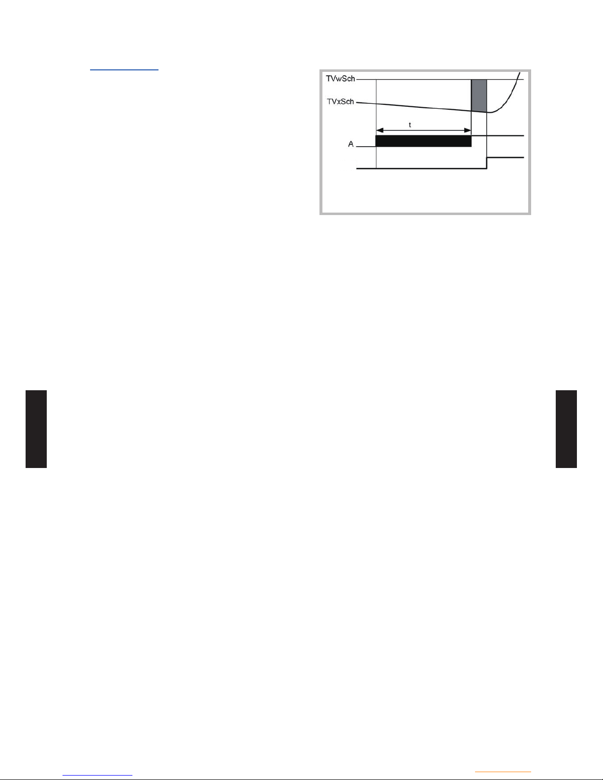
- (CS01 - 46) -
Control system
- (CS01 - 46) -
CONTROL
SYSTEM
CONTROL
SYSTEM
Locking time
The locking time enables the heat pump to reach
a stable operating state before the supplementary
source is allowed to switch on.
The supplementary source is released only when
the locking time has elapsed.
The locking time starts as soon as a valid ow
temperature setpoint is available.
Calculation of the release integral starts only when
the locking time has elapsed.
TVxSch Actual value of common flow temperature
TVwSch Setpoint of common flow temperature
A Request
QX2 Release output QX2
T Locking time
QX2
No consideration is given to the locking time, if
the heat pump malfunctions or is locked, or if the
supplementary source must end DHW charging.
Setting "- - -" can be used to deactivate the
function.
 Loading...