

Water Right ISP1-1044, ISP1-1054, ISP2-1354, ISP2-1044, ISP2-1054 Installation Instructions & Owner's Manual
...
Installation Instructions & Owner’s Manual
IRON SOFT PLUS™SERIES
Water Conditioners

TABLE OF CONTENTS:
Installation Instructions Page 3-4
Start-up Procedures Page 5-6
Programming the Iron Soft Plus Timer Page 6-8
Light/Alarm Operation Page 9
Water Conditioner Flow Diagrams Page 9-10
Troubleshooting Page 11-12
Parts & Assembly Diagrams Page 13-18
Blank Page 19
Capacity & Physical Specifications Page 20
Your Iron Soft Plus Series water conditioners are precision built, high quality products. These units will deliver
conditioned water for many years to come, when installed and operated properly. Please study this manual
carefully and understand the cautions and notes before installing. This manual should be kept for future
reference. If you have any questions regarding your water conditioner, contact your local dealer.
YOUR WATER TEST
Hardness gpg
Iron ppm
pH number
*Nitrates ppm
Manganese ppm
Sulphur yes/no
Total Dissolved Solids
*Over 10 ppm may be harmful for human consumption. Water
conditioners do not remove nitrates or coliform bacteria, this
requires specialized equipment.
CAUTION: The manufacturer does not recommend the use of any
resin cleaners. Please refer to page 6 in this manual or the warning
label on the back of the brine tank.
3
PRE-INSTALLATION INSTRUCTIONS:
Although the Iron Soft Plus Series Water Conditioner is shipped complete, some assembly may be required.
1. After unboxing the unit, please note that on most models the control valve is installed on the tank. If not,
remove “split flange” from control valve adapter base, remove cardboard tank shim. Inspect “O” Ring on
top of flange and grease with silicone provided. Place valve (shipped in a separate box) on adapter base.
The valve is “keyed” and will only attach one way. Using split flange, attach control valve to tank.
CAUTION: The “split flange” should secure the valve with the top of the flange
facing up. Please note “top” on the split flange.
2. Install the chlorine generator on the brine valve (Fig. 3) by inserting 3/8" tube and tightening the
nut. Plug generator’s electrical end into receiving adapter from the back plate. Do not install brine
line at this time.
CAUTION: Never grab onto the generator to move unit. This will result in
cracking the valve body.
3. Install meter and bypass, if ordered, (Fig. 3) using silicone grease provided on “O” Rings.
Extra “O” Rings have also been provided in case a tear occurs during installation.
NOTE: Meter should be installed between the control valve and the bypass with the meter
“turbine” being installed on the outlet side of the control valve (Fig.3).
4. Secure both the meter and the bypass using the clips provided.
NOTE: There will be some up and down “play” and should not be of concern since
the “O” Rings will seal and no leaks should occur.
INSTALLATION INSTRUCTIONS:
IMPORTANT: In the following installation instructions various types of plumbing pipe are recommended.
These types may or may not be approved for your local plumbing codes. All plumbing must be installed
according to local plumbing codes.
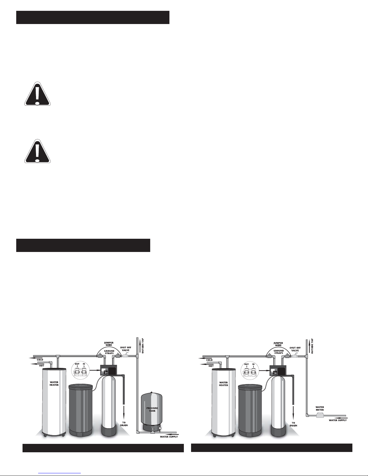
WELL WATER INSTALLATION
Figure 1
MUNICIPAL INSTALLATION
Figure 2
1. A selection site should be chosen for your conditioner. If you have a well system, this would be
after the pressure tank but before the hot water heater (Fig. 1). If you have city water, install the
softener on the inlet line to the building before the hot water heater (Fig. 2).
NOTE: Try to locate the softener as close to a drain (floor drain, sump pump, etc.) as possible.
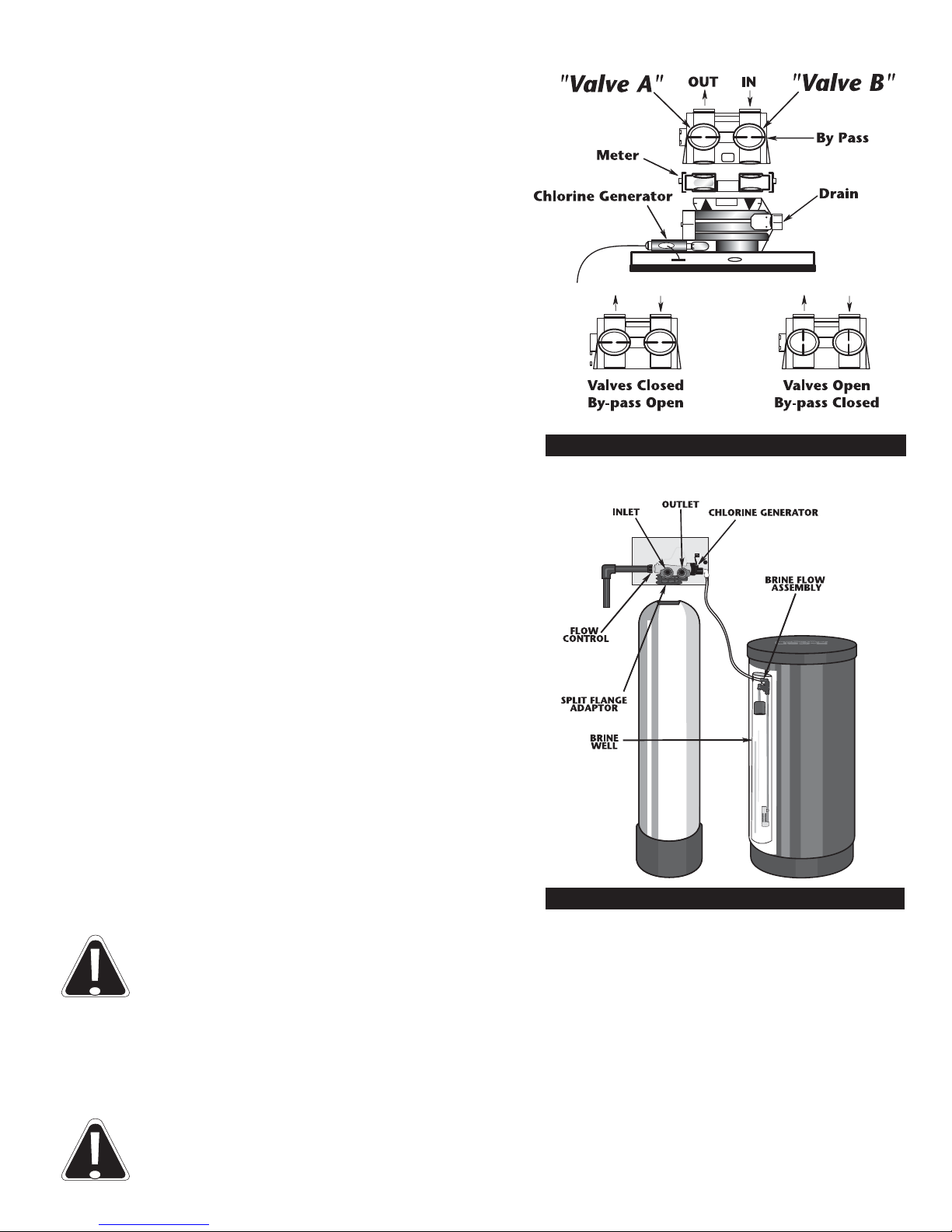
2. Notice on the casting, the inlet and outlet
markings, make sure the incoming water is
plumbed to the inlet and outlet is plumbed to
service (Fig. 3). Your water softener must be
installed with a bypass valve. If your conditioner is
not equipped with one, make a provision in the
plumbing system for a bypass to be installed.
IMPORTANT: Make sure the water is turned
off and pressure is released before a cut is made
into plumbing system. At this time you should
also make provisions for hard water lines to
outside tap and anywhere else desired.
3. To “bypass” your water conditioner, turn valves
A & B to the bypass open position (Fig. 3.). This
will supply unconditioned water to the house.
4. Check local plumbing code for approved piping.
The size diameter of pipe should be equal to the size
opening of the casting or larger.
5. In the brine tank there is a piece of flexible brine tube.
This tube runs from the brine flow control assembly (in the
brine tank, Fig. 4) to the chlorine generator, located on the
control head. Remove chlorine generator from valve and
insert tubing into generator, fitting firmly; pull on tubing
making sure it is secure. Do not attach other end to the
brine tank, as this will be covered in start-up procedures.
Reattach generator to valve, making sure clip is secure.
NOTE: Brine line should go into elbow
approximately 3/4".
6. The drain line must be connected from the drain line
flow control (Fig. 4), to a floor drain, sump pump, etc.
This pipe is not provided with your water conditioner
and is the responsibility of the installer. Check your local
plumbing code for approved piping. In any case, it should
be of adequate inside diameter to allow for proper
drainage. Secure pipe to flow control and run to drain.
CAUTION: Make sure the drain, drain control and clip are attached securely to
the control valve before start up.
IMPORTANT: A 2" air gap is required on the drain line.
7. Notice the elbow protruding from the brine tank. It is recommended to run a line from this elbow to
the drain. This is a precautionary step in case of brine tank overflow. A separate line should be run.
CAUTION: Never connect the brine tank overflow line and drain line together;
however, the same drain may be used.
Figure 4
TOP VIEW
Figure 3
4
5
• After installation is complete, rotate bypass handles to bypass mode (see “Valves Closed” in Fig.3).
• Turn on water and check for leaks.
• Fully open a cold water faucet — preferably a laundry sink or bathtub with no aerator.
• Allow water to run until clear to rid pipes of debris which may have occurred during installation.
NOTE: The system regeneration sequence for the Iron Soft Plus Conditioner.
Backwash
Regenerate (Brine)
Rapid Rinse
Fill
Service
The system is now ready for filling with water. For the purpose of filling the softener, leave the unit
in the bypass position until the 2nd step, then repeat steps 1-6 with the unit full. Do not open the
bypass at this time, it will be filled in the backwash position. Once the unit is filled with water
(step 2), then open the bypass.
1. With the softener in the bypass mode (“Bypass valve,” Fig. 3) and the control valve in normal
operation where the display shows either the time of day or the gallons remaining:
Manually add 5 GALLONS of water to the regenerant tank.
NOTE: If too much water is put into the brine tank during softener startup, it could result in a salty
water complaint after the first regeneration.
During the first regeneration the unit will draw out the initial volume of brine/regenerant and refill
it with the correct preset amount.
2. Press and hold the button for 5 seconds.
NOTE: You will hear a click, indicating the valve will go into regeneration. There is a 10-second
delay until the motor starts to advance, the unit is now in the backwash position. Once motor has
stopped, open inlet handle (“Valve B,” Fig. 3) of the bypass valve very slightly allowing water to
fill the tank slowly in order to expel air. Once air is expelled and water is running at drain, open
inlet to control.
CAUTION: If water flows too rapidly it could result in loss of media to the
drain. When the water is flowing steadily to the drain without the presence
of air, slowly open the inlet valve. Check that the drain can receive the flow
of water. Restore power.
3. Connect brine line to brine tank. Press button again to put the valve into BRINE position.
Display will flash No. 2 until position is reached. Check the brine line for section. Verify that water is
being drawn from regenerant tank with no air leaks or bubbles in the brine line. There should be a
slow flow to the drain.
4. Press button and place unit into rinse position. Display will flash No.3 until position is reached.
Check drain line to be secure and see that drain can receive the flow of water. There should be a rapid
flow to the drain. Unplug transformer to keep the valve in the RINSE position. Allow to run until clear
and without air. While the unit is rinsing, load the brine tank with water softener salt.
START-UP PROCEDURES FOR ELECTRONIC CONTROLLER:
6
CAUTION: Damage or destruction to the media may occur if salts containing additives
are used with the Iron Soft Plus models. Most “solar” and/or “block” salts do not
contain additives detrimental to this unit. If unsure, please check with manufacturer.
Many “pellet” or “cube” type salts are formulated with cleaning agents or additives
which can cause harm to the media. Salt manufacturers do not always list additives in
their products. Please check with salt manufacturers for any cleaning agents, binders
or phosphate material added to salt.
NOTE: The manufacturer does recommend the brine tank be cleaned once a year to discard
accumulated dirt from the salt.
5. Press the button and place unit into the brine tank fill position. Check to verify that the
regenerant tank is filling at a rate of 1/2 gallon per minute. Check Brine line connections for leaks.
NOTE: See page 18, Safety Float Assembly, Item No. 2, for location of 1/2 gpm Refill Flow Control.
6. Press button again, valve will cycle back to the normal operating position with the time of day
and gallons remaining displayed.
7. Repeat steps 1-6 and now check the various cycles for proper operation.
8. Once the cycle operation has been verified, place bypass valve in the normal operating mode
(“Valves Open,” Fig. 3) by opening the outlet bypass handle.
9. Go to laundry tub or bathtub faucet, preferably a faucet without an aerator, and turn on the cold water,
let the water run. Note the color of water coming from faucet. If discolored let water run until clear.
NOTE: At no time should there be “large particles” of media noticed at faucet or laundry tub. If this
is seen, immediately shut off water and bypass system as this could be an indication of a distributor
failure. Contact manufacturer or distributor for assistance.
START-UP PROCEDURES FOR ELECTRONIC CONTROLLER CONT’D:
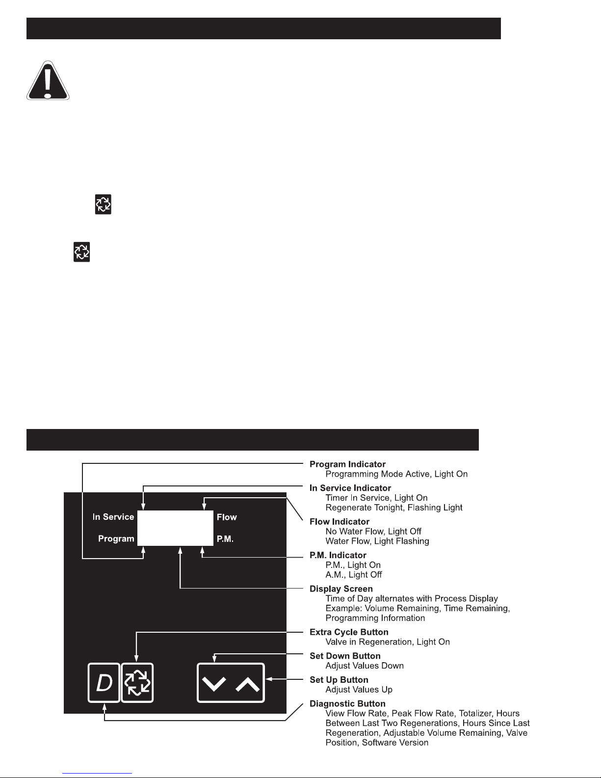
TIMER DISPLAY DESCRIPTION
:
 Loading...