

Page 1

ECLIPSE
Reverse Osmosis
Drinking Water Sys tem
from Water-Right
Installation, Operation & Service Manual
WRO-35
R.O. Drinking
Water System
Sold and serviced
by authorized
Water-Right dealers.
Tested and Certifi ed by NSF International against
NSF/ANSI Standard 58 for the reduction of the claims
specifi ed on the Performance Data Sheet.
Page 2

TABLE OF CONTENTS
Page
SECTION I. INTRODUCTION ...................................................................................3
SECTION II. SPECIFICATIONS ................................................................................4
SECTION III. PREPARATION......................................................................................5
A. Major System Components.............................................................5
B. Tools Recommended for Installation ...............................................7
C. Site Selection For Major System Components ...............................7
SECTION IV. INSTALLATION STEPS .........................................................................8
A. Faucet with Water Quality Monitor Installation ................................8
B. Feed Water Saddle Valve Installation............................................10
C. Drain Clamp Installation ................................................................10
D. R.O. Manifold Assembly Installation..............................................11
E. Position the Drinking Water Holding Tank
and Make the Final Hose Connections .........................................12
F. Start Up.........................................................................................13
SECTION V. OPERATION AND MAINTENTANCE ..................................................13
A. Normal Operation..........................................................................13
B. Changing Modules ........................................................................14
C. Changing the In-Line Activated Carbon Post Filter .......................14
SECTION VI. TECHNICAL DATA...............................................................................14
A. Water Quality ................................................................................14
B. Water Quantity ..............................................................................15
C. Net Pressure Differential ...............................................................15
D. Water Production Rate Chart ........................................................17
SECTION VII. TROUBLE SHOOTING GUIDE ...........................................................18
EXPLODED VIEW AND PARTS LIST ...................................................................................21
CAUTION:
The Centers for Disease Control and Prevention (CDC) and the Environmental Protection Agency (EPA) have issued guidance to people with severely
weakened immune systems who may want to take extra precautions to reduce the risk of infection with Cryptosporidium from drinking water. This
guidance pertains to people with HIV/AIDS, patients receiving treatment for cancer, recipients of organ or bone marrow transplants, transplant patients
taking immunosuppressive drugs, and persons who have congenital immunodefi ciencies.
The EPA has stated that they do not know the signifi cance of drinking water compared to other possible sources of Cryptosporidium to determine how
most people become infected. The CDC-EPA guidance suggests that immunosuppressed individuals discuss their risks with their health care provider.
This drinking water system is tested and Certifi ed by NSF International to NSF/ANSI Standard 58 for cyst reduction. It meets the NSF/ANSI standard of
reducing at least 99.95%* of cysts (including Cryptosporidium), however, because this is not 100%, immunosuppressed individuals should take the extra
precaution of boiling their drinking water. According to the CDC-EPA, bringing water to a rolling boil for one minute is the most certain approach for killing
Cryptosporidium.
All individuals should take adequate precautions when changing the fi lter cartridges, including wearing protective gloves, to avoid direct contact with the
exhausted cartridges.
*For complete specifi cations, refer to the Performance Data Sheet.
Page 3

SECTION I. INTRODUCTION
Your new Reverse Osmosis (R.O.) Drinking Water
System uses a combination of fi ltration tech nol o gies
to reduce unwanted contaminants in a water supply.
The following steps combine to give you the best in
clear sparkling drinking water:
MECHANICAL FILTRATION/ACTIVATED
CARBON–The Sediment/Carbon Module will
remove the larger particles such as silt, rust
and scale. Its 5 micron (equal to 0.0002 inch)
nominal rating
R.O. Membrane.
helps to give maximum life to the
The activated carbon in the
Prefi lter will remove any chlo rine that may be
present in the feed water. This pre treat ment is
also necessary for membrane protection.
REVERSE OSMOSIS MEMBRANE–The R.O.
Membrane is the heart of the fi l tra tion system.
It is designed to reduce the dis solved min er al
content of the water. Minerals picked up in the
environment by the water are measured as Total
Dissolved Solids (TDS). In the Reverse Os mo sis
process, dissolved minerals are sep a rat ed from
the incoming water (Feed Water) to produce
the product wa ter (the Permeate). The excess
minerals are rinsed to drain (the Reject Water).
The membrane is a specially con struct ed, fully
aromatic polyamide fi lm, and is classifi ed as a
Thin Film Composite (T.F.C.).
The spiral wound construction of the R.O.
Membrane provides maximum surface area
for water production and is less susceptible
to fouling by par tic u late matter, turbidity and
colloidal ma te ri als.
ACTIVATED CARBON–The Ac ti vat ed Carbon
Module contains carbon particles with a vast
network of pores. The tremendous surface
area of these pores (typically 800–1200 square
meters per gram of carbon) gives the carbon
very good adsorptive sites for sub stanc es that
contribute to tastes and odors.
IN–LINE ACTIVATED CARBON POST FILTER–
The In–Line Activated Carbon Post Filter is
located after the Holding Tank and reduces the
tastes and odors that may pass through the
system. It adds a fi nal polish to the water.
AUTOMATIC SHUTOFF VALVE–The ASO Valve
senses when the Holding Tank is full and closes
the feed water supply to prevent excess reject
water from going to drain when the unit is not
producing water.
WATER QUALITY MONITOR–The Water Quality
Monitor has been integrated into the faucet
base for instant monitoring at the touch of a
button. The monitor compares the level of the
Total Dissolved Solids in the incoming (feed)
water versus the product water and calculates
the percent rejection. The monitor is preset to
indicate a level of 75% rejection.
A green light indicates that the percent rejection
is at or above the set (desired) value and that
the system is producing quality water.
An amber light indicates that the product water
quality is less than acceptable. Because the
Water Quality Monitor was designed to operate
best while the system is making water, a false
reading may occur if tested when your R.O.
drinking water system is not
making water.
Please empty the Holding Tank, wait 15 minutes
for the system to begin making water, and test
your water quality again. If the Water Quality
Monitor light is still amber, please contact a
water treatment professional for service. The
Water Quality Monitor requires a 9 volt battery,
which is included.
IMPORTANT NOTICES:
This reverse osmosis system contains replaceable treatment components critical for effective performance. It is the user's
responsibility to, and the manufacturer strongly recommends that the user, periodically test the product water to verify the
system is performing satisfactorily. See the test kit(s) for sampling instructions.
This system is acceptable for treatment of infl uent concentrations of no more than 27 mg/l nitrate and 3 mg/l nitrite in
combination measured as N and is certifi ed for nitrate/nitrite reduction only for water supplies with a pressure of 40 psig
(280 kPa) or greater.
This system conforms to NSF/ANSI Standard 58 for pentavalent arsenic reduction. See the Performance Data Sheet and
Arsenic Facts section for an explanation of reduction performance.
DO NOT USE WITH WATER THAT IS MICROBIOLOGICALLY UNSAFE OR OF UNKNOWN QUALITY, WITHOUT
ADEQUATE DISINFECTION BEFORE OR AFTER THE SYSTEM. Systems certifi ed for cyst reduction may be used on
disinfected water that may contain fi lterable cysts.
3
Page 4
SECTION II. SPECIFICATIONS
TABLE A – QUALIFIED SYSTEM PER FOR MANCE
Because the performance of an R.O. Mem brane is highly dependent upon pressure, temperature and TDS, the
following should be used for com par i son purposes only.
U.S. Metric
1
Membrane Production
Membrane TDS Reduction
35 ± 7 gpd (106–159 lpd)
1
95% minimum 95% minimum
System Production² 11 gpd 42 lpd
TDS Reduction² 90%+ typical 90%+ typical
Drain (reject water) Flow 3–5 x product fl ow 3–5 x product fl ow
Empty Storage Tank Precharge 5–7 psig air 35–48 kPa air
Storage Tank Capacity
1
Industry standards measure RO Mem branes performance with no backpressure on the product water, at 60 psig (414kPa) and
77°F (25°C). Further conditions on the above are 250 ppm TDS and a 15% recovery rate. Production rate and TDS reduction
fi gures are for a new Membrane that has been rinsed for 24 hours. The production rate of a new Membrane can decrease by
10% per year or more, depending upon the scaling and fouling ten den cies of the Feed Water.
2
Measured at 50 psig, 77°±2°F, and 717 mg/l TDS per NSF/ANSI Standard 58.
2
1.8 gallons 6.8 liters
TABLE B – RECOMMENDED OPERATING LIMITS FOR FEED WATER
Specifi cations T.F.C. Membrane
Water Pressure 40–100 psig (280–690 kPa)
TDS 2000 ppm (also mg/l) max.
Temperature 40–100°F (4–38°C)
pH 3–11
Hardness Less than 10 gpg (170 mg/l) or soften
Iron Less than 0.1 ppm (also mg/l)
Manganese Less than 0.05 ppm (also mg/l)
Hydrogen Sulfi de None
Chlorine See note
Bacteria Must be potable**
NOTE: Chlorine will damage a T.F.C. Membrane. The Sediment/Carbon Module will remove chlorine from the incoming water.
Change fi lter every 6 months, more often if the water contains more than 1 ppm chlorine.
**DO NOT USE WITH WATER THAT IS MI CRO BI O LOG I CAL LY UN SAFE OR OF UNKNOWN QUALITY, WITHOUT AD E QUATE DIS IN FEC TION BEFORE OR AFTER THE SYSTEM.
4
Page 5
SECTION III. PREPARATION
A. Major System Components
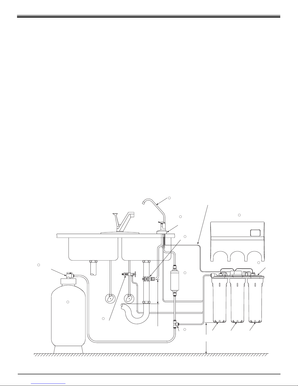
The following components comprise the R.O.
Drinking Water System. (Refer to Fig. 1, below
for general system layout.)
• A Sediment/Carbon Module, shrink wrapped.
• An Activated Carbon Module, shrink
wrapped.
• An R.O. Manifold assembly.
• Housings and Housing O–rings.
• A Drinking Water Holding Tank.
• A Dispensing Faucet with Water Quality
Monitor Assembly.
• A Feed Water Saddle Valve.
• A Drain Clamp.
• Plastic Tubing and tube connectors.
• A Reverse Osmosis Mem brane sealed in a
plastic bag.
TYPICAL WRO-35 UNDER SINK INSTALLATION DIAGRAM
11
NITRATE/NITRITE
TEST KIT
• An In–Line Activated Carbon Post Filter,
shrink wrapped.
• Other items necessary for installation may
include wood screws or machine screws and
nuts for mounting the manifold, or concrete
anchors for hanging on basement wall.
Additional tubing or tube connectors. Plastic
wire ties for organizing tubing.
1
DISPENSING
FAUCET WITH
AIR GAP
2
WATER QUALITY
MONITOR
FAUCET BASE
WATER QUALITY
MONITOR CABLE
4
COVER
10
HOLDING TANK
SHUTOFF VALVE
(Open Position)
9
DRINKING
WATER
HOLDING
TANK
SADDLE VALVE
(COLD WATER LINE ONLY)
3
DRAIN
CLAMP
DRAIN
(3/8" Black)
8
LOCATE DRAIN CLAMP ABOVE
"P" TRAP
TANK
(3/8" Yellow)
PRODUCT
(3/8" Blue)
6
IN-LINE
ACTIVATED
CARBON
POST FILTER
(1/4" Black)
(1/4" Red)
(1/4" Yellow)
7
POLYTUBE
TEE
DRAIN
INLET
4" MIN.
ACTIVATED
CARBON
MODULE
REVERSE
OSMOSIS
MEMBRANE
HOUSING
5
RO MANIFOLD
SEDIMENT/
CARBON
MODULE
Figure 1
5
Page 6
FLOOR
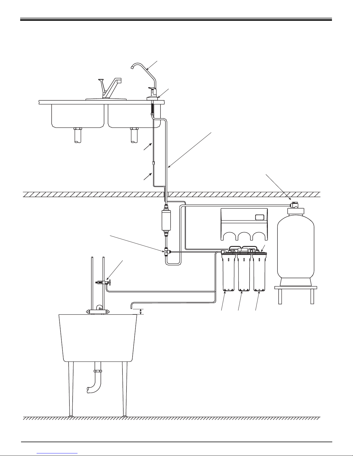
OPTIONAL WRO-35 BASEMENT INSTALLATION DIAGRAM
DISPENSING
FAUCET
WATER QUALITY
MONITOR
FAUCET BASE
NOTE: FOR REFRIGERATOR
WATER DISPENSER OR ICE
MAKER HOOKUP, TEE INTO
WATER QUALITY
MONITOR CABLE
OPTIONAL 25 FT. EXTENSION
CABLE FOR WATER QUALITY
MONITOR
PRODUCT
(3/8" Blue)
3/8" BLUE TUBING TO
DISPENSING FAUCET
HOLDING TANK
SHUTOFF VALVE
(Open Position)
POLYTUBE
TEE
IN-LINE
ACTIVATED
CARBON
POST FILTER
FEED WATER
SADDLE VALVE
(COLD WATER
LINE ONLY)
1" AIR GAP
REQUIRED
INLET
(1/4" Red)
DRAIN
(1/4" Black)
TANK
(3/8" Yellow)
(1/4" Yellow)
ACTIVATED
CARBON
MODULE
COVER
R.O. MANIFOLD
REVERSE
OSMOSIS
MEMBRANE
HOUSING
SEDIMENT/
CARBON
MODULE
DRINKING
WATER
HOLDING
TANK
MOUNT HOLDING
TANK ON SHELF OR
STRAP BETWEEN
FLOOR JOISTS
(Shelf Or Straps Not
Included)
BASEMENT
FLOOR
PLEASE NOTE: IF AIR GAP ON FAUCET IS NOT USED IN BASEMENT
INSTALLATIONS, A PROPER AIR GAP MUST BE CREATED. PLEASE
CHECK WITH LOCAL PLUMBING CODES. SEE EXAMPLE ABOVE.
6
Page 7

B. Tools Recommended for Installation
The following tools will cover most of the
in stal la tion sites encountered:
3
1.
/8" variable speed electric drill.
2. Extension work light with outlet.
3. Safety glasses.
4. 1¼" porcelain hole cutter kit.
5. 1¼" Greenlee hole punch and
1
/8" and
½" metal drill bits for pilot hole.
6. Center punch and hammer.
7. 1¼" wood bit.
8. Concrete drill bits.
9. Assorted wood and metal drill bits in clud ing
7
/32" metal drill bit.
10.Phillips head and fl at blade screwdrivers.
11.½",
9
/16" and 5/8" open end wrenches.
12.10" Crescent wrench with jaws taped to hold
faucet.
13.Basin wrench or 10" pipe wrench.
14.Tefl on tape.
15.Wide masking tape or duct tape.
16.Plastic tubing cutter.
17.Extra plastic tubing.
18.Low range air pressure gauge.
19.Bicycle hand air pump.
20.Small bottle of liquid chlo rine bleach.
21.Graduated measuring cyl in der.
22.Paper towels, wisk broom and assorted clean
up materials.
1. Dispensing Faucet–The faucet should be
placed near the sink where drinking water
is normally obtained. Convenience of use
(fi lling of water pitchers and glasses), and an
open area beneath the faucet under the sink
for attaching product and drain tubing are
considerations. A 2" diameter fl at surface is
required above and below the installation site.
The thickness of the mount ing surface should
not exceed 1¼". Watch for strengthening
web bing on the underside of cast iron sinks.
2. Drinking Water Holding Tank–The Holding
Tank may be placed where it is convenient
within 10 feet of the faucet; under the sink or
in an ad ja cent cabinet are best the choices.
If a longer run of tubing is required, the
tubing should be the
3
/8" diameter OD size
to prevent a high pres sure drop. Re mem ber,
these tanks can weigh up to 30 pounds when
full of water; a fi rm, level area is required.
3. R.O. Manifold Assembly–The manifold can
be installed on either the right or left side
of the under–sink area or a cabinet. The
right side is recommended because all the
tubing will be to the back of the cabinet and
out of the way. Installation in the basement
is also an option; one location is near the
laundry/utility sink where cold potable water
and drain access are handy. The mounting
location should allow adequate clear ance
and accessibility for cartridge chang es.
4. Feed Water Connection–The Feed Water
Saddle Valve should be located as close to
the manifold assembly as possible. USE A
POTABLE COLD WATER SUPPLY ONLY.
Softened water is preferred as it will extend
the life of the R.O. Membrane.
C. Site Selection for Major System Components
The R.O. System was designed to fi t under a
sink, however, because of space limitations
or other reasons, the system’s fl exible design
allows for other lo ca tions. When determining the
location re mem ber that access to a cold water
tap line, the household drain, and ease of fi lter
re place ment are important considerations.
All components and tubing should be located in
an area not exposed to freezing temperatures. If
winter temperatures are severe, the area should
be above the minimum temperature listed in
Table B, page 4 for proper performance. Do not
expose unit or tubing to direct sunlight.
5. Drain Connection–The waste water must
go to drain through an anti–siphon air gap.
The air gap is pro vid ed for in the base of
the faucet. If discharging into a utility sink
or standpipe, an air gap of greater than 1"
above the fl ood rim must be provided.
Do NOT connect the system drain line to
the dishwasher drain or near the garbage
dis pos al. Backpressure from these units may
cause the air gap to overfl ow.
7
Page 8

SECTION IV. INSTALLATION STEPS
All plumbing should be done in accordance with
state and local plumbing codes.
NOTE: Some codes may require installation by a
licensed plumber; check with the local plumbing
authority prior to installation.
In restricted under–sink areas, it may be easier to
install the faucet fi rst. Allow ad e quate tubing lengths
for any fi nal component position.
A. Faucet With Water Quality Monitor Installation
The faucet contains an anti–siphon air gap.
–
While the system is producing water, the drain
water fl ows from the R.O., through the air gap
and then to the household drain. The purpose of
the air gap is to prevent water in the drain from
backing up into the R.O. Drinking Water System.
NOTE: For proper installation the Air Gap Faucet
has a critical level line “CL” marked on its body
and should be mounted so that the “CL” line is at
least one (1) inch (26mm) above the fl ood level
rim of the sink.
The easiest installation is to use an existing
spray attachment hole. If the spray faucet hole is
not available, then the sink top must be drilled.
Choose a convenient location as described in
Sec. III, C.1, page 7.
1. Mark the location of the center of the faucet
base.
2a.Drilling a stainless steel sink:
•Center punch the hole to provide a starting
point for the drill.
•Start with a smaller drill as a pilot, and then
drill a ½" diameter hole to accept the bolt of
a 1¼" Greenlee Hole Punch (1¼" chassis
punch).
•Clean away any chips.
•Install the punch and tighten the nut to cut
the hole.
•Deburr any sharp edges.
2b.Drilling a porcelain sink:
It is best to use a special 1¼" diameter cutter
designed for porcelain. A carbide tipped
masonry bit is a second choice.
•Place a piece of tape over the area to be
drilled to help prevent chip ping.
•Drill a pilot hole for the porcelain cutter.
Use the pilot drill supplied with the kit or a
car bide tipped drill.
•When drilling the 1¼" hole, drill slowly and
carefully; the porcelain chips easily.
•After drilling, clean the area well. Iron fi lings,
if left in place, can cause rust stains.
2c. Drilling a counter top:
NOTE: The counter top must be less than
1¼" thick. Treat ceramic tile as por ce lain until
the tile is pen e trat ed, then use the carbide
tipped metal cutter.
Formica counter tops may be drilled with a
good 1¼" wood bit; drilling a
3
/32" pilot hole
will help keep the bit going straight.
3. Assemble and attach the Faucet, Water
Quality Monitor Faucet Base and tubing (refer
to Fig. 2A & 2B, page 9.)
•Assemble the Body and Spout by removing
the plastic ship ping plug from the Body and
then fi rmly pressing in the Spout.
Locate the ¼" Black Drain Tubing which
is shipped loose in the box. Connect the
Black Drain Tubing to the ¼" Hose Barb on
the Dispensing Faucet by fi rmly pressing
over the barb. Allow the tubing to relax,
then press fi rmly again to insure proper
seating. The end of the Black Drain Tubing
that should be inserted into the "Drain" port
on the R.O. Manifold will have a blue drain
restrictor in it. DO NOT attach this end to
the Dispensing Faucet.
Locate the
3
/8" Black Drain Tubing which is
shipped loose in the box. Firmly press one
3
end of the tubing over the
/8" drain outlet
hose barb on the Dispensing Faucet. Allow
tubing to relax, then press fi rmly again to
insure proper seating. No connectors are
required when attaching tubing to Hose
Barbs.
Slide Water Quality Monitor Faucet Base
over ¼" Black Drain Tubing, 3/8" Black Drain
7
Tubing and
/16" stud screw and seat with
Amber/Green LED's aligned under Air Gap
Window on Dispensing Faucet. (See Figure
2A, page 9.)
Assemble the Plastic Spacer (with open
end upwards and facing tubing), the
7
Washer and the
/16" Hex Nut onto the 7/16"
7
/16"
stud screw. Do Not tighten at this point.
8
Page 9
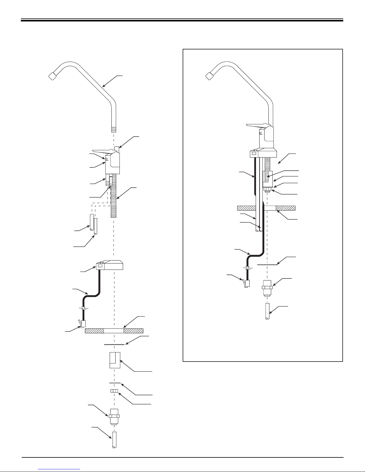
LONG REACH AIR GAP FAUCET WITH WATER QUALITY MONITOR
Spout
Air Gap Window
Critical Level
3/8" Hose Barb for
3/8" Black Drain Tubing to
1/4" Black Drain Tubing to
3/8" Black Drain Tubing
1/4" Black Drain Tubing
Water Quality Monitor
Water Quality
Monitor Cable
Drain Clamp
1/4" Hose Barb for
Manifold Drain Port
Faucet Base
Line
Plastic Shipping
Plug (Remove)
CL
Water Quality
Monitor Cable
7/16" Stud
3/8" Black Drain Tubing
1/4" Black Drain Tubing
Water Quality
Monitor Cable
Water Quality
Monitor Connector
CL
Allow space for
thickness of Mounting
Surface and Slotted
Washer
}
7/16" Stud
Plastic Spacer
7/16" Washer
7/16" Hex Nut
Mounting Surface,
1¼" drill hole
Slotted Washer
3/8" Polytube
Quick Connect
Fitting
3/8" Blue Polytube
Water Quality
Monitor Connector
3/8" Polytube
Quick Connect
Fitting
3/8" Blue Polytube
Mounting Surface,
1¼" drill hole
Slotted Washer
Plastic Spacer
7/16" Washer
7/16" Hex Nut
Figure 2A
NOTE: Assemble Slotted Washer, 3/8" Polytube Quick
Connect Fitting and 3/8" Blue Polytube after faucet
assembly has been placed through the mounting surface.
Figure 2B
9
Page 10

•From the top of the counter place the stud,
tubing and Water Quality Monitor Connector
Cable through the mounting hole. See
Figure 2B, page 9.
•From the bottom of the counter top slide the
Slotted Washer between the counter top
and the Plastic Spacer with the open end
towards the tubing.
7
Tighten the
/16" Hex Nut to hold everything
in place.
•Rotate the Spout and Body into position
making sure the faucet body is square and
properly aligned with the Water Quality
Monitor Faucet Base. Align the Slotted
Washer and the Spacer to allow access to
the Hose Barbs, and tighten the Hex Nut
while holding the faucet in alignment with
a padded crescent wrench. Do not over
tighten.
•To the end of the
3
/8" Polytube Quick Connect Fitting. Once
7
/16" stud, screw on the
snug by hand take a pair of pliers and
tighten the fi tting an additional half turn.
Don’t over tighten.
Locate the
Firmly press one end into the
3
/8" Blue Product Water Tubing.
3
/8" Polytube
Quick Connect Fitting.
Note: If you want to pull the tubing out for
some reason, push the ring around the
tubing in and pull the tubing out.
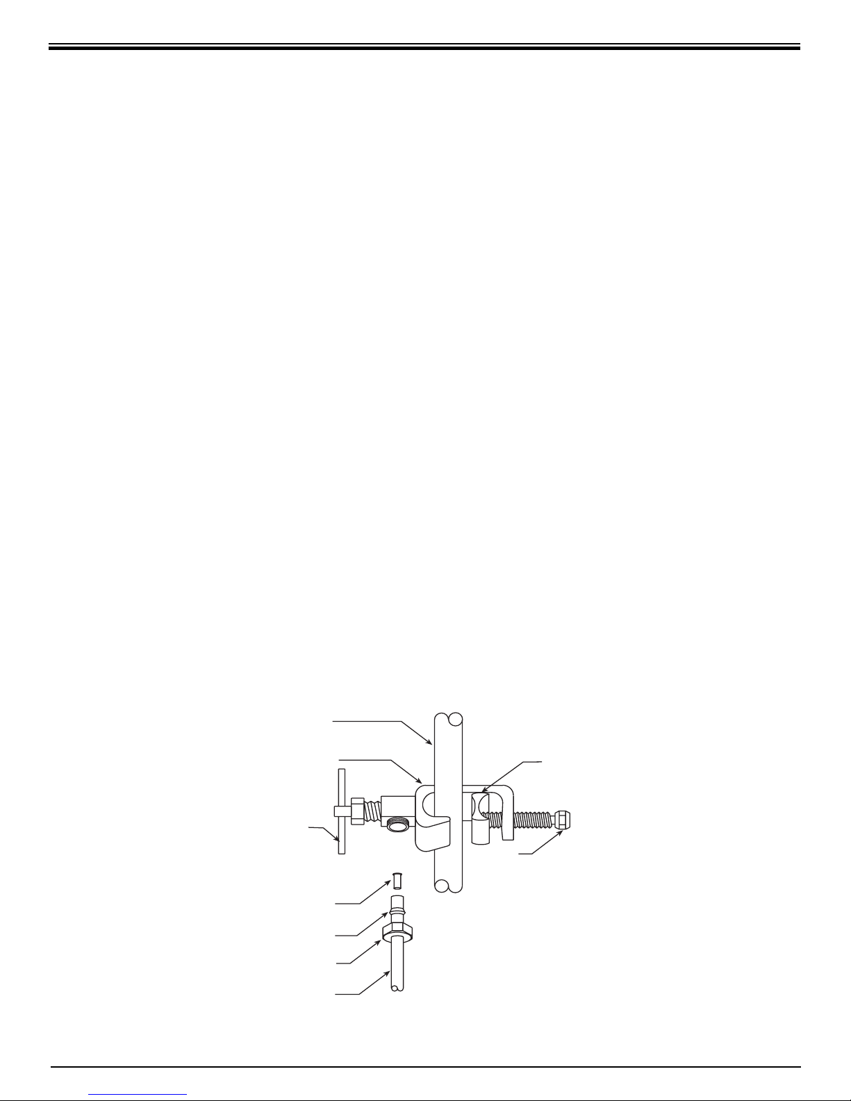
B. Feed Water Saddle Valve Installation
Decide on location. Do NOT connect to a
hot water feed line. If you are not sure of the
supply, run the hot water and feel the supply
piping. Wa ter over 100°F may cause permanent
dam age to the R.O. Membrane. (Refer to Fig. 3
page 11.)
1. Shut off the water supply and drain the line.
2a.To install on (soft) Copper Tubing supply
line:
•Turn the Handle of the Feed Water Saddle
Valve counter clockwise (outward) until the
lance does not protrude from the gasket. It
may have to be pushed in.
•Assemble the Feed Water Saddle Valve on
the tubing.
3
–for
/8" OD tubing use the back plate side
with the small groove to prevent dis tor tion of
the tub ing.
–for larger tubing (up to
5
/8" OD) use the
large groove of the back plate.
•Assemble and tighten the brass screw.
•To pierce the tubing, turn the Valve Handle
fully clock wise (inward). A small amount of
water may escape from the outlet until it is
fully pierced.
•When you feel the Valve Handle fi rmly
seated in the clockwise direction, the
copper tube is pierced and the valve is
closed.
2b.To install on (hard) Steel or Brass Tubing
supply line.
•The supply line should now be drained. Use
a battery powered or properly ground ed drill
to avoid shock hazard.
•Drill a
3
/16" hole in the supply line; (do not
drill through the opposite wall).
•Turn the handle to expose the lance no more
3
than
/16" beyond the rubber gasket.
•Place the body of the valve over the hole so
that the lance fi ts into the hole.
•Assemble and tighten the brass screw.
•Turn the Valve Handle clockwise (inward)
until fi rmly seated. The valve is closed.
3. With the Feed Water Saddle Valve closed,
open the sink faucet and the water supply
and allow the water to run for a few minutes
to fl ush any debris caused by the in stal la tion.
•Close the faucet and check the Feed Water
Saddle Valve for leaks.
C. Drain Clamp Installation
Choose the drain outlet location per Sec. III, C.5,
page 7.
The following are instructions for discharging into
the sink drain pipe. (Refer to Fig. 1, page 5.)
1. Position the Drain Clamp on the sink drain
pipe above the drain trap. Allow room for
drilling. Tighten securely.
2. Use a battery pow ered or properly grounded
drill. Using the Clamp port as a drill guide,
7
drill a
/32" hole through the wall of the drain
pipe. Do NOT penetrate the opposite side of
the pipe.
3. Locate the
3
/8" Black Drain Tubing connected
10
Page 11
to the Dispensing Faucet. Route to the tubing
to the Drain Clamp and trim to length.
NOTE: When cutting the polytubing make
clean, square cuts, failing to do so could
result in poor con nec tions and possible leaks.
CAUTION: The lowest point of the line
should be the point of connection to the Drain
Clamp. There should be no sag in the line as
this may cause ex ces sive noise as the reject
water is fl owing to drain.
•Refer to Fig. 4, page 12. Insert the tubing
into the Drain Clamp. Make sure the
tubing is pressed all the way in to create a
pressure tight connection.
NOTE: If you want to pull the tubing out for
some reason, push the ring around the
tubing in and pull the tubing out.
D. R.O. Manifold Assembly Installation
Locate the site per Sec. III, C.3, page 7. Various
in stal la tion sites will require different types
of mount ing fasteners; be sure the fastener
selected will provide a fi rm, solid mounting.
A support panel may be necessary on thin
cabinet walls or to span between wall studs on
par ti cle board or drywall.
Do not drill through exterior cabinet walls or
leave sharp wood screw points exposed in
readily accessible cabinet interiors.
The close proximity of a dishwasher or a trash
compactor may require spe cial fabrication of a
mounting plate.
1. The mounting bracket will accept either #10
or #12 (5mm) mounting screws spaced on
6" (15 cm) centers. Allow at least 4" (10 cm)
of clearance beneath the fi lter housings to
accommodate fi lter changes. Mark the two
locations (the bracket can be used as a
template). Install the screws and tighten them
until the heads are about
5
/8" from the wall.
2. Locate the ¼" Red Feed Water Tubing.
Remove the red plug from the fi tting labelled
“In” on the manifold and insert the tubing.
Reference the special supplement sheet in
the carton for proper connection of all tubing
and removal of plugs. Run the tubing along
its course to the Feed Water Saddle Valve,
trim to length. (Refer to Fig. 1, page 5.)
Refer to Fig. 3,. To the end of the red
polytube install the Compression Nut, the
Plastic Ferrule, and the Insert. Connect to the
Feed Water Saddle Valve.
3. Locate the ¼" Black Drain Tubing connected
to the Dispensing Faucet. Remove the black
plug from the fi tting labelled “Drain” on the
manifold and insert the tubing. The end of the
Black Drain Tubing that should be inserted
into the “Drain” port will have a blue drain
restrictor in it. If tubing needs to be trimmed
Cold Water
Valve
Handle
Compression
Red Tubing To
FEED WATER SADDLE VALVE
Line
Saddle
Tightening
Insert
Plastic
Ferrule
Nut
Manifold
Inlet
Figure 3
11
Screw
Reversible
Back Plate
Page 12
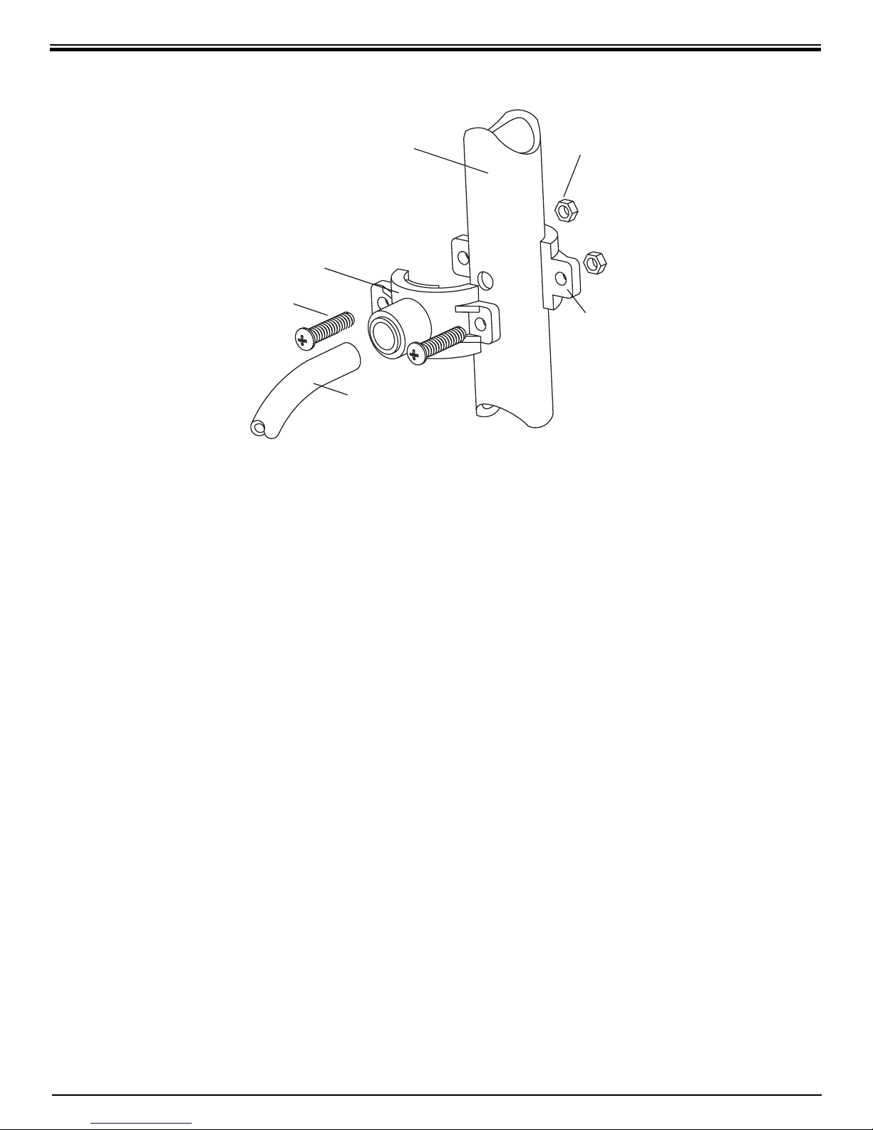
3/8" DRAIN CLAMP ASSEMBLY
Drain Pipe
Drain Clamp
Front Plate
1/4" Screw
Black Drain Tubing
to length, carefully slit ¼" Black Drain Tubing
end that has the blue drain restrictor in it
being careful not to damage the hose barb
on the drain restrictor. Remove restrictor from
tubing, make a square cut, and reinsert the
drain restrictor. Allow the tubing to relax, then
press drain restrictor fi rmly again to insure
proper seating.
1/4" Nut
Drain Clamp
Back Plate
Figure 4
convenient to install and change the In–Line
Fil ter. Make a clean straight cut to insure
proper connections. The “Out” port on the
In–Line Filter should be towards the faucet.
Firmly press in the tubing. The fi ttings will
grab the tubing and hold and seal it in place.
Make sure the tubing is pressed all the way
in to create a pressure tight connection.
4. Locate the ¼" yellow tubing with the tee
attached to one end. Remove the yellow plug
from the fi tting labelled "Out" on the manifold
and insert the tubing.
3
5. Locate the
/8" Blue Product Water Tubing
attached to the Dispensing Faucet. Firmly
press one end into the tee. (Refer to Fig.
1, page 5.) The fi ttings will grab the tubing
and seal it in place. Make sure the tub ing is
pressed all the way in to create a pressure
tight connection.
NOTE: If you want to pull the tubing out
for some reason, push the ring around the
tubing in and pull the tubing out.
6. Hang the Manifold Assembly on the
mounting screws and tighten. DO NOT
OVERTIGHTEN.
7. Remove the wrap ping from the
In–Line Activated Carbon Post Filter. Slice
3
the
/8" Blue Polytube where it would be
E. Position the Drinking Water Hold ing Tank and
Make the Final Hose Connections.
1. Check the tank precharge pressure. Make
sure it is between 5 to 7 psig. If not, use a
bicycle hand pump or other pump to bring the
pressure up to the 5 to 7 psig range.
2. Pull the cap/plug off the top of the tank where
the Tank Shut–Off should go. (Refer to Fig. 1,
page 5.)
3. Wrap the white Tefl on tape, included in the
box, three times around the ¼" male outlet
thread. Wrap in the direction of the threads
(clockwise when looking down on the Holding
Tank). The tape will act as a thread sealant.
Screw on the Holding Tank Shut–Off Valve.
4. Locate the
3
/8" Yellow Tubing. Firmly press
one end into the Holding Tank Shut–Off Valve
and the other end into the tee. (Refer to Fig.
1, page 5.) The fi ttings will grab the tubing
12
Page 13

and seal it in place. Make sure the tubing is
pressed all the way in to create a pressure
tight connection.
rinsing of the R.O. Membrane it is important
to wait at least 8 hours before emptying
each tank.
F. Start Up
1. Installing the modules and membrane and
sanitizing the holding tank.
•Open the Dispensing Faucet by lifting the
black handle and close the Holding Tank
Shut–Off Valve (the handle should be
perpendicular to the valve body).
•Remove the plug on the underside of the
manifold labelled “SEDIMENT/CARBON”.
Unwrap the Sediment/Carbon Module.
Make certain the Module O-ring is pressed
fi rmly in the groove. Engage and fi rmly
tighten the module hand tight only.
•Remove the plug labelled "Membrane"
from the underside of the manifold. Trim
top of membrane bag, exposing the white
plastic seal. While holding onto bag, insert
membrane into manifold. (The O-rings
should be up towards the manifold.) Take
the remaining housing and insert housing
O-ring into its groove. Engage and fi rmly
tighten housing hand tight only.
•Remove the plug labelled “ACTIVATED
CARBON” from the underside of the
manifold. Unwrap Activated Carbon
Module. Make certain Module O-ring is
fi rmly pressed in groove. Engage and fi rmly
tighten the module hand tight only.
•Close the Holding Tank Valve.
•Disconnect the yellow product water tubing
that runs from the Holding Tank to the Tee
(see Fig. 1, page 5). Put 50 drops of bleach
(this is ½ tsp. or 3 ml) into the tubing and
reconnect the Tee.
2. Rinsing the system:
•Slowly open the Feed Water Saddle Valve
fully counter clockwise.
•Open the Holding Tank Valve.
•Check the Air Gap Window on the
Dispensing Faucet to be sure that the drain
water is fl owing. (Refer to Figure 2A, page
9.) The R.O. System is now making water.
•Do not open the Faucet for at least 8 hours.
•Do not use the fi rst three full tanks of water.
CAUTION: The R.O. Membrane is shipped
with a preservative in it. To ensure proper
When the Faucet is fi rst opened, expect air
and carbon fi nes (very fi ne black powder)
from the In–Line and Activated Carbon Post
Filters to be rinsed out. This is normal for
the fi rst tank of water or after the Activated
Carbon Post Filters are changed.
SECTION V. OPERATION & MAINTENANCE
A. Normal Operation
1. It is normal for the Total Dissolved Solids
(TDS) of the water to be higher than normal
during the fi rst 5 gallons of operation; this is
due to the sanitizing solution and the new
Post Filters. After this water is rinsed to drain,
the removal rate should stabilize at a value of
greater than 75%. The Water Quality Monitor
was designed to measure water quality when
the R.O. system is making water. In order to
assure you are getting an accurate reading,
empty the holding tank, wait 15 minutes until
the system begins making water, and then
test the TDS with the monitor.
2. R.O. systems produce drinking water at
relatively slow rates; it can take up to 5 hours
or more to fi ll the Holding Tank. Normal
operation is to let the Holding Tank fi ll with
water and then draw water as is needed.
When the pressure in the Holding Tank falls
to a given pressure (as the water is being
used) the Automatic Shut–Off Valve (ASO
Valve) will start water production and the
system will refi ll the Holding Tank. When the
Hold ing Tank is full and no water is being
used, the ASO Valve will automatically shut
off the feed water to conserve water. The
more water that is used (up to the capacity
of the system) the better the R.O. system will
function. Other uses for the water are fl owers,
pets and rinsing glassware.
With each use it is recommended that you
run the tap for at least 10 seconds prior to
using water. Thi s is especially important
if the water tap has not been used daily.
After periods of non–use, such as a week
of vacation, it is better to empty the Holding
Tank and allow the system to produce fresh
wa ter for use. If the system is not used for
3–4 weeks or longer, it is a good idea to
resanitize the system and to change the
13
Page 14

prefi lter and post fi lters.
B. Changing Modules
THIS R.O. SYSTEM CONTAINS MODULES
WHICH MUST BE REPLACED AT REGULAR
INTERVALS TO MAINTAIN PROPER
PERFORMANCE. USE ONLY FACTORY
APPROVED MODULES.
All individuals should take adequate precautions
when changing the fi lters, including wearing
protective gloves, to avoid direct contact with the
exhausted fi lters.
The recommended interval for changing the
modules (not the R.O. Membrane) is every
six (6) months. Typical T.F.C. Membrane life
expectancy is three years. Local con di tions may
dictate more frequent changes.
NOTE: If the R.O. Membrane is to be replaced,
see Sec. IV, F.1–2, page 13, for the proper
pro ce dure.
Use a drip pan to catch any water that may spill
when the Filter Modules are removed. Refer to
Fig. 1 page 3 for component location.
1. Close the Feed Water Saddle Valve by
turning fully clockwise and open the
Dispensing Faucet by lifting the handle. Allow
the Holding Tank to empty.
2. Loosen and remove the Sediment/Carbon
Module and the Activated Carbon Module.
Discard the modules.
3. To sanitize the system and replace the
modules:
•Unwrap the new Sediment/Carbon Module.
•Using an eyedropper put 5 ml (this is
approximately 1 tsp.) of a good quality
unscented 5¼% liquid household chlorine
bleach down the center tube of the Module.
•Check the Module O-ring for proper position
in its groove, engage and tighten the
Module hand tight only.
(see Fig. 1, page 5). Put 50 drops of bleach
(this is ½ tsp. or 3 ml) into the tubing and
reconnect it to the Tee.
NOTE: Now is the convenient time to
change the In–Line Activated Carbon Post
Filter, see Sec. V, C.1–6.
•Slowly open the Feed Water Saddle Valve.
When water begins dripping out of the
Dispensing Faucet, in the following order,
close the Faucet and then open the Holding
Tank Valve.
•Do not open the Faucet for at least 8 hours.
•Discard the fi rst three full tanks of water
pro duced, they will contain chlorine.
C. Changing the In–Line Activated Carbon Post
Filter
1. Close the Feed Water Saddle Valve by
turning fully clockwise.
2. Close the Holding Tank Valve and then
open the Dispensing Faucet to release the
pressure.
3. Remove the In–Line Activated Carbon Post
Filter. Disconnect the used Post Filter by
pressing in the connector’s collar and at the
same time pulling the tube out of the fi tting.
Unscrew the fi ttings on the In–Line, re–Te fl on
tape them and install them on the new Post
Filter. Do not over tighten the fi ttings.
4. Firmly reconnect the polytubes to the new
Post Filter. (Refer to Fig. 5, page 15.)
5. Slowly open the Feed Water Saddle Valve.
6. When water begins dripping out of the
Faucet, in the following order, close the
Faucet and open the Holding Tank Valve.
When the Faucet is fi rst opened, expect air
and carbon fi nes (very fi ne black powder),
from the new Post Filter to be rinsed out. This
is normal for the fi rst tank of water.
•Unwrap the new Activated Carbon Module.
•Check the Module O-ring for proper position
in its groove, engage and tighten the
Module hand tight only.
•Close the Holding Tank Valve.
•Disconnect the yellow product water tubing
that runs from the Holding Tank to the Tee
SECTION VI. TECHNICAL DATA
A. Water Quality
Water quality is normally measured with a
special meter that measures the water’s ability
to conduct electricity. The more dissolved solids
in the water, the higher the conductivity. The
results are usu al ly reported in Parts per Mil lion
(ppm) or Milligrams per Liter (mg/l) of Total
Dissolved Solids (TDS). (Al though technically
14
Page 15
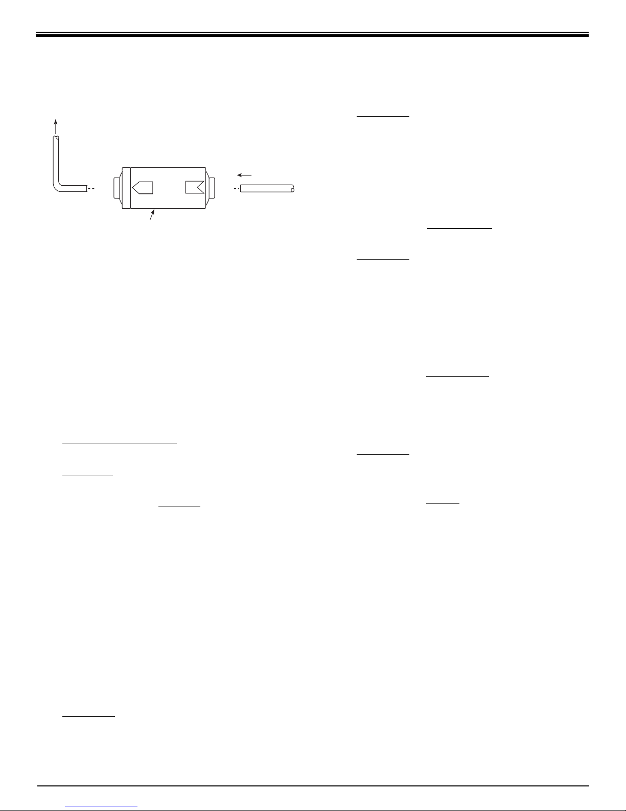
OUT
v
ated
C
er
3/8
e
T
o
g
aucet
3/8
e
Dispensin
IN–LINE ACTIVATED CARBON
POST FILTER ASSEMBLY
If the container available measures ounces, use
the following conversion:
Ounces per minute x 11.2 = gallons per day
EXAMPLE: The product fl ow will fi ll 2½ ounces
in two min utes.
" Blu
In-Line Acti
arbon Post Filt
Figure 5
they are not exactly equal, in most dis cus sions
ppm = mg/l.)
R.O. Membranes are rated by the amount of
dissolved solids that are rejected. This rating is
a ratio of the TDS in the feed water to the TDS
in the product water and is reported as Percent
Rejection. If the feed water contained 100 ppm
of TDS and the product water contained 10 ppm
of TDS, 90 ppm have been rejected and the
reject ratio is 90%.
Percent Rejection =
Feed TDS–Product TDS
x 100%
Feed TDS
EXAMPLE: Feed water is 500 ppm TDS and the
product water is 75 ppm TDS.
Percent Rejection = 500 – 75
x 100%
500
Percent Rejection = 0.85 x 100% or 85%
" Blu
2.5 oz. ÷ 2 min. = 1.25 oz./min.
1.25 oz./min. x 11.2 = 14 gpd
The Reject Ratio is the amount of water
pro duced compared to the amount of
water fl owing to drain.
Reject Ratio = Reject Rate_
Product Rate
EXAMPLE: The product rate is 14 gpd and the
reject rate is 56 gpd.
Reject Ratio = 56 ÷ 14
Reject Ratio = 4 or 4–to–1
The Percent Recovery is another way to
measure the amount of water produced as
compared to the amount actually used.
% Recovery = Product Rate
x 100%
Feed Rate
NOTE: The total fl ow or feed water rate into the
system is the sum of the product fl ow and the
drain fl ow.
EXAMPLE: The product water rate is 14 gpd and
the drain water rate is 56 gpd
Feed Rate = 14 gpd + 56 gpd = 70 gpd
% Recovery = 14 gpd
x 100%
70 gpd
% Recovery = 0.20 x 100% or 20%
B. Water Quantity
Water quantity is termed Flux or Product Water
Rate and is measured as the amount of water
pro duced in one day. It is reported as Gallons
per Day (gpd) or Liters per Day (lpd).
The fl ow of water to drain is the Reject Water
Rate and is measured as Gallons per Day (gpd)
or as Milliliters per Minute (ml/min).
Milliliters per minute x 0.38 = gallons per day
EXAMPLE: The drain fl ow will fi ll a graduated
cylinder to the 150 ml mark in one minute.
150 ml/min. x 0.38 = 57 gpd
C. Net Pressure Differential
Most R.O. Membranes are rated at a
standardized condition of 77°F (25°C) and
65 psig (450kPa) discharging to atmospheric
pressure.
Product water quality and quantity greatly
depend upon the Net Pressure Differential
(Dp) across the R.O. Membrane. This pressure
dif fer en tial is a summation of the feed water
pressure at the Membrane, which tries to push
the water through, the pressure in the Holding
Tank, which tries to push the water backwards
and the osmotic pressure, which also tries to
push the water backwards.
The Osmotic Pressure is in proportion to the
15
Page 16

dissolved minerals in the water and can be
ap prox i mat ed by 1 psig for each 100 ppm of TDS
EXAMPLE: A feed water with 1500 ppm of TDS
would exert a backward pressure of about 15
psig on the membrane.
Net Pressure Differential =
Feed Water Pressure – Holding Tank Pressure –
Osmotic Pressure
The higher the net pressure differential,
the higher the quantity and quality of water
produced.
Some loss of production is normal when using a
pressurized Holding Tank.
16
Page 17
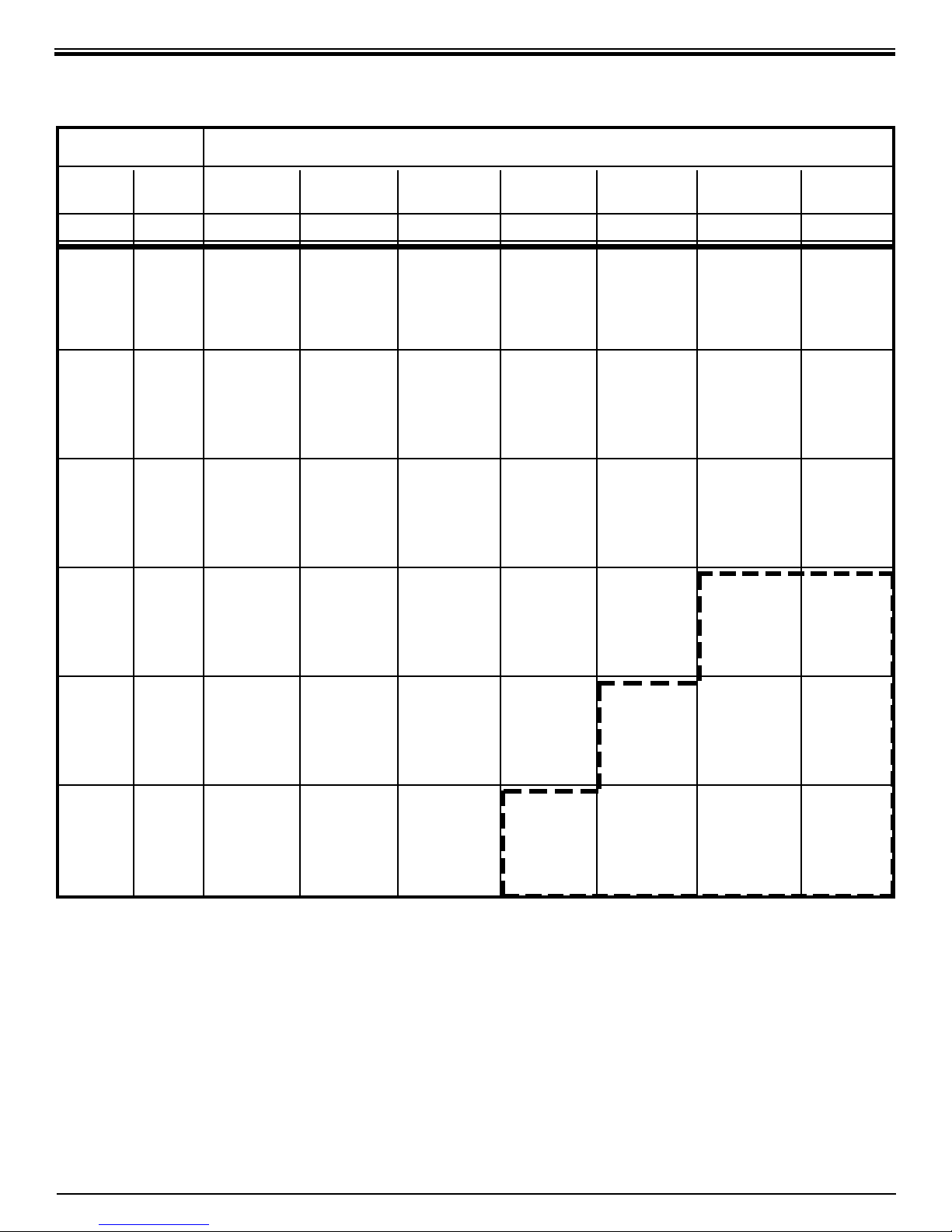
D. WATER PRODUCTION RATE CHART
Estimated Water Production Rate
Feed Water in Gallons Per Day (gpd) and Liters Per Day (lpd) for Line Pressure of:
40 psig 50 psig 60 psig 70 psig 80 psig 90 psig 100 psig
Temp TDS* (280 kPa) (345 kPa) (414 kPa) (483 kPa) (552 kPa) (621 kPa) (690 kPa)
°F °C mg/l gpd lpd gpd lpd gpd lpd gpd lpd gpd lpd gpd lpd gpd lpd
40 4 50 6.5 24.6 8.5 32.2 10.5 39.7 12.5 47.3 14.5 54.9 16.5 62.5 18.5 70.0
500 5.6 21.2 7.6 28.8 9.6 36.3 11.6 43.9 13.6 51.5 15.6 59.0 17.6 66.6
1000 4.6 17.4 6.6 25.0 8.6 32.6 10.6 40.1 12.6 47.7 14.6 55.3 16.6 62.8
1500 3.6 13.6 5.6 21.2 7.6 28.8 9.6 36.3 11.6 43.9 13.6 51.5 15.6 59.0
50 10 50 9.9 37.5 12.9 48.8 15.9 60.2 19.0 71.9 22.0 83.3 25.0 94.6 28.1 106.4
500 8.5 32.2 11.5 43.5 14.6 55.3 17.6 66.6 20.6 78.0 23.7 89.7 26.7 101.1
1000 7.0 26.5 10.0 37.9 13.0 49.2 16.1 60.9 19.1 72.3 22.1 83.6 25.2 95.4
1500 5.5 20.8 8.5 32.2 11.5 43.5 14.6 55.3 17.6 66.6 20.6 78.0 23.7 89.7
60 16 50 13.2 50.0 17.3 65.5 21.4 81.0 25.4 96.1 29.5 111.7 33.6 127.2 37.7 142.7
500 11.4 43.1 15.5 58.7 19.5 73.8 23.6 89.3 27.7 104.8 31.7 120.0 35.8 135.5
1000 9.4 35.6 13.4 50.7 17.5 66.2 21.6 81.8 25.6 96.9 29.7 112.4 33.8 127.9
1500 7.3 27.6 11.4 43.1 15.5 58.7 19.5 73.8 23.6 89.3 27.7 104.8 31.7 120.0
70 21 50 16.6 62.8 21.7 82.1 26.8 101.4 31.9 120.7 37.0 140.0 42.1 159.3 47.2 178.7
500 14.3 54.1 19.4 73.4 24.5 92.7 29.6 112.0 34.7 131.3 39.8 150.6 44.9 169.9
1000 11.7 44.3 16.9 64.0 22.0 83.3 27.1 102.6 32.2 121.9 37.3 141.2 42.4 160.5
1500 9.2 34.8 14.3 54.1 19.4 73.4 24.5 92.7 29.6 112.0 34.7 131.3 39.8 150.6
80 27 50 20.0 75.7 26.1 98.8 32.3 122.3 38.4 145.3 44.5 168.4 50.7 191.9 56.8 215.0
500 17.2 65.1 23.3 88.2 29.5 111.7 35.6 134.7 41.8 158.2 47.9 181.3 54.1 204.8
1000 14.1 53.4 20.3 76.8 26.4 99.9 32.6 123.4 38.7 146.5 44.9 169.9 50.1 189.6
1500 11.1 42.0 17.2 65.1 23.3 88.2 29.5 111.7 35.6 134.7 41.8 158.2 47.9 181.3
90 32 50 23.3 88.2 30.5 115.4 37.7 142.7 44.9 169.9 52.1 197.2 59.2 224.1 66.4 251.3
500 20.1 76.1 27.3 103.3 34.5 130.6 41.7 157.8 48.8 184.7 56.0 212.0 63.2 239.2
1000 16.5 62.5 23.7 89.7 30.9 117.0 38.1 144.2 45.2 171.1 52.4 198.3 59.6 225.6
1500 12.9 48.8 20.1 76.1 27.3 103.3 34.5 130.6 41.7 157.8 48.8 184.7 56.0 212.0
*
Total Dissolved Solids (TDS) measured in Parts Per Million (ppm)/Milligrams per Liter (mg/l).
Please Note: This chart is based upon a start–up of a system when the storage tank is empty, (7 psig/48 kPa precharge).
As the tank fi lls, and backpressure from the tank increases, the gpd/lpd rating will decrease.
IMPORTANT! If the water production rate is within the highlighted area (marked with dotted lines), change the
drain restrictor to a 125 gpd (473 lpd) drain restrictor, color-coded purple.
17
Page 18
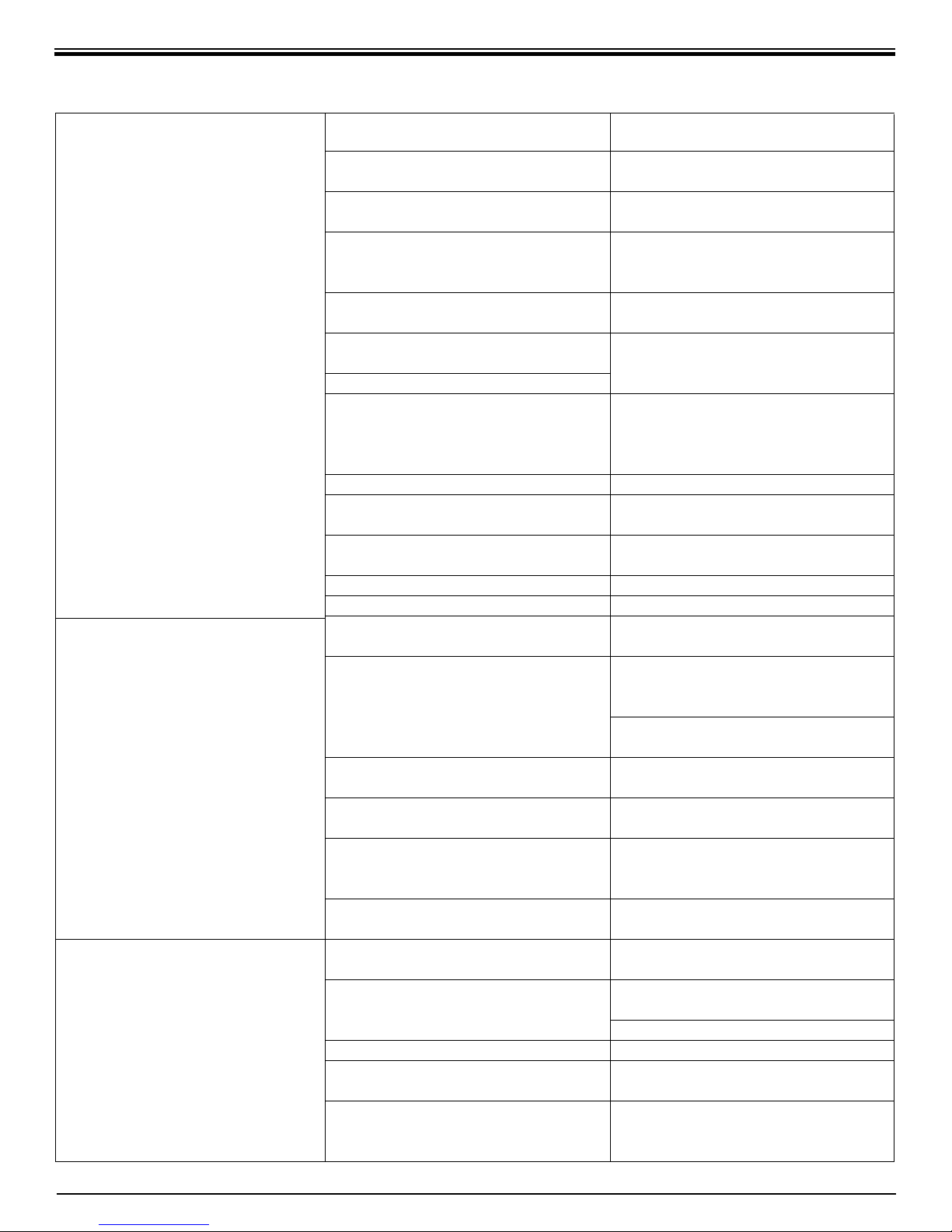
SECTION VII. TROUBLE SHOOTING GUIDE
Problem Possible Cause So lu tion
Low quantity of Product Water
from Holding Tank
Feed Water Saddle Valve is plugged or
closed.
Clogged Sediment/Carbon Module or
Activated Carbon Module.
Low water pressure.
R.O. Membrane is fouled.
Plugged In–Line Activated Carbon
Post Filter.
Air precharge pressure in Holding
Tank is too high.
Air precharge is too low
Air bladder in the Holding Tank is
rup tured.
Open Valve or unclog.
Replace Modules.
Feed Water pressure must be above
40 psig.
See Feed Water operating limits.
Correct cause of fouling, replace
Membrane.
Replace Post Filter.
Empty water from Holding Tank,
and with the faucet open, adjust air
pressure to 5–7 psig (35–48 kPa) range.
Replace tank.
Low pressure at the Dispensing
Faucet
High Total Dissolved Solids (TDS)
in the Product Water
Holding Tank Valve is closed.
No drain fl ow, the Drain Restrictor
is plugged.
No drain fl ow, the drain orifi ce in the
Air Gap Faucet is plugged.
The Check Valve is stuck.
The ASO Valve is malfunctioning.
In–Line Activated Carbon Post Filter
is plugged.
Air precharge in the Holding Tank is
too low.
Holding Tank Valve is partially
closed.
The dispensing Faucet is out of
adjustment or faulty.
Heavy water use, Holding Tank is
depleted.
Low Water Production.
Clogged Sediment/Carbon Module or
Activated Carbon Module.
Low Water Pressure.
R.O. Membrane O–ring is crimped.
R.O. Membrane brine seal is not
sealing up into the manifold head.
R.O. Membrane is expended.
Open Valve.
Clear or replace Drain Restrictor.
Clear or replace the Air Gap Faucet.
Free check.
Replace ASO Valve components.
Replace Post Filter.
Empty water from Holding Tank and
with the faucet open, adjust the air
pressure to 5–7 psig (35–48 kPa) range.
Check for leakage at the Air Valve
Stem.
Open Valve.
Repair or replace Dispensing Fau cet.
Allow Holding Tank to refi ll (adding
a second Holding Tank will increase
storage capacity).
See Low Quantity of Product Water
from Holding Tank section above.
Replace Modules.
Feed Water Pressure must be above
40 psig.
Check Feed Water Saddle Valve.
Check O–ring.
Check the brine seal.
If Membrane life is unusually short,
fi nd and correct the problem.
Replace Membrane.
18
Page 19
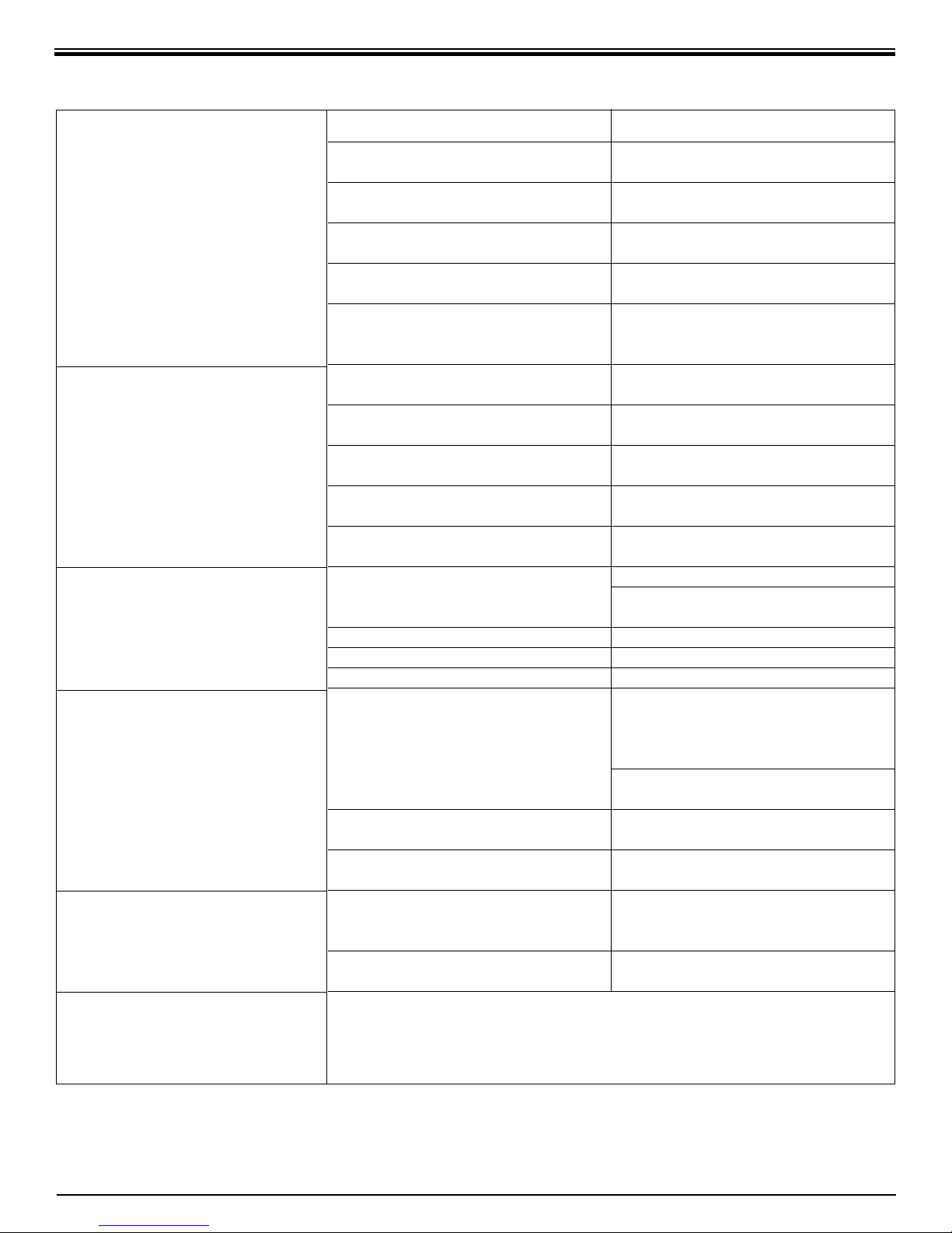
Problem Possible Cause So lu tion
High Total Dissolved Solids (TDS)
in the Product Water
(continued)
Tastes and odors in the Product
Water
Drain Water overfl ows at the Air
Gap Faucet
Faucet leaks or drips
Amber light on Water
Quality Monitor
Fitting leaks in general
The Product Water and Drain Water
lines are reversed.
No drain fl ow, Drain Restrictor is
clogged.
No drain fl ow, the drain orifi ce in
the Air Gap Faucet is plugged.
The ASO Valve is not closing.
New Activated Carbon Post Filter not
rinsed com plete ly.
The Feed Water TDS has increased.
The Activated Carbon Post Filter is
exhausted.
There is foreign matter in the Hold ing
Tank.
The Product Water and Drain Water
lines are reversed.
Dissolved gasses in the Feed Water.
Increase in Product Water TDS.
Air Gap is blocked.
Drain tubing is clogged.
Drain Clamp hole is misaligned.
Excessive drain fl ow rate.
Leaks from spout.
Leaks from base of the delivery
tube.
Leaks from beneath the handle.
System not being used for extended
period of time
Filters are plugged or membrane is
fouled or exhausted.
Close the Feed Water Saddle Valve and relieve pressure before dis con nect ing
any tubing or re plac ing any fi tting. Before replacing a fi tting, re–cut the tubing
and re–insert into the fi tting to see if that solves the leak. If pipe threads are
leaking, remove and retape with Tefl on tape.
Correct plumbing.
Clear or replace Drain Restrictor.
Clear or replace Air Gap Faucet..
Repair or replace the ASO Valve
Com po nents.
Flush with several full tanks of
Product Water.
An increase in Feed Water TDS will
give a corresponding increase in
Product Water TDS.
Replace Filter.
Clean, fl ush and sanitize the system.
Replace the fi lters.
Correct plumbing.
Pretreat Feed Water to remove
dissolved gasses.
See high TDS in the Product Water
section.
Clear Air Gap.
Rinse with vinegar for removal of
calcium buildup.
Clear tubing.
Align with hole in the drain pipe.
Replace Drain Restrictor.
Adjust Faucet by turning the tee bar
just below the handle to provide a
small amount of free play in handle
when shut off.
O–rings are bad, repair or replace
faucet.
O–ring is bad, replace O–ring.
O–rings are bad. Repair or replace
the faucet.
Empty storage tank. Wait 15 minutes
(the system is making water)
and test water quality again.
Replace fi lters and/or membrane.
19
Page 20

NOTES:
20
Page 21
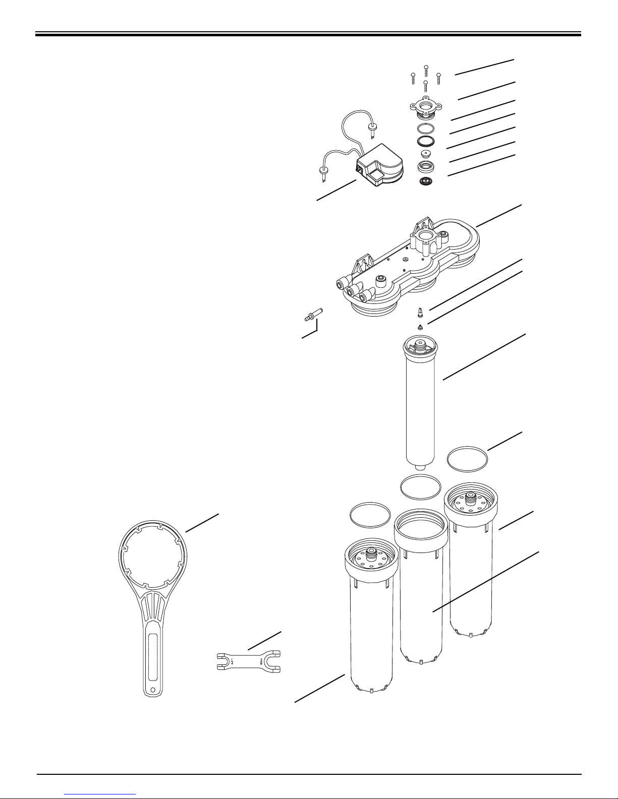
EXPLODED VIEW & PARTS LIST
21. Nitrate/Nitrite Test Kit
1
2
3
4
5
6
7
16
15
8
9
10
12
13
19
11
14
18
MADE IN USA
17
21
Page 22
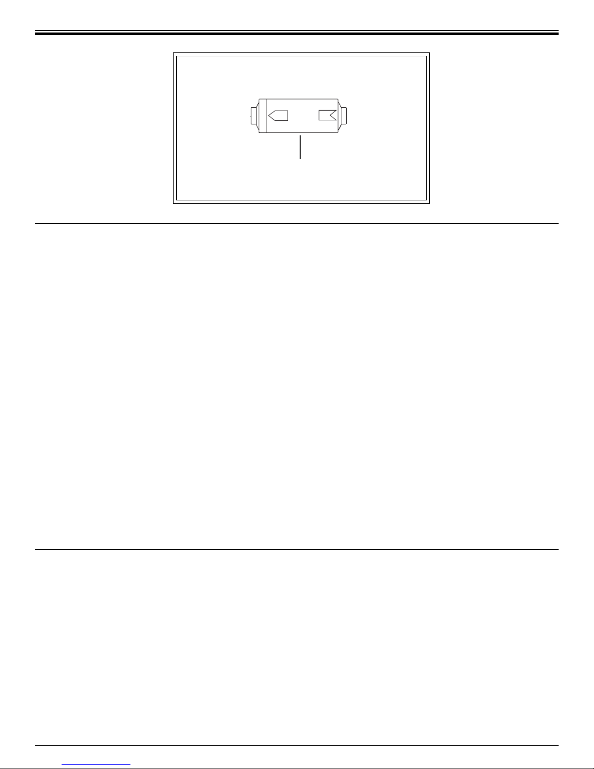
OUT
IN
20
DRAWING NO. PART NO. DESCRIPTION
1.................... S2009................................ Self Tapping Screw
2.................... S2005................................ ASO Cap
3.................... S2013................................ ASO Cap O–Ring
4.................... S2011................................ ASO Diaphragm – Large
5.................... S2007................................ ASO Piston
6.................... S2006................................ ASO Piston Ring
7.................... S2010................................ ASO Diaphragm – Small
8.................... S2128-M............................ Manifold Plate
9.................... S1276................................ Check Valve
10.................... S1277................................ Check Valve Retainer
11.................... S7128X ............................. Sediment/Carbon Module
12.................... S1448RS........................... T.F.C. RO Membrane 35 gpd/132 lpd
13.................... S3069................................ Housing O–Ring
14.................... S3010................................ Housing
15.................... R7078................................ Water Quality Monitor w/Probes and Cover
16.................... S2116–8............................ Drain Restrictor 80 GPD/303 lpd Blue
17.................... S7125X ............................. Activated Carbon Module
18.................... S1405................................ 1/4"–3/8" Fitting Wrench
19.................... S3072................................ Wrench for Housing
20.................... S7206W ............................ In–Line Activated Carbon Post Filter
21.................... S1447................................ Nitrate/Nitrite Test Kit
(shown on pg. 6) .... R2118................................ Water Quality Monitor 25 Ft. Extension Cable
OTHER COMPONENTS AS SHOWN IN FIGURE 1, PAGE 5.
DRAWING NO. PART NO. DESCRIPTION
1.................... S1089–08.......................... Long Reach Air Gap Faucet w/ 3/8" Connector
2.................... R7091-01BLK.................... Water Quality Monitor Faucet Base
3.................... S1117–01.......................... 3/8" Drain Clamp Assembly
4.................... S2122................................ Cover
7.................... JG-PI301208S................... 3/8" x 3/8" x 1/4" Union Tee
8.................... S1118–01.......................... Feed Water Saddle Valve
9 ................... C2000................................ Steel Holding Tank
10.................... S1037................................ Holding Tank Shut–Off Valve
22
Page 23

Page 24

ECLIPSE™ R.O. DRINKING WATER SYSTEM
FIVE/ONE YEAR LIMITED WARRANTY
What Does This Warranty Cover?
This warranty covers any defects in materials and workmanship of the Eclipse R.O. Drinking Water System
when installed and operated within recommended parameters, with the exceptions stated below.
How Long Does The Coverage Last?
Water-Right
for a period of fi ve years from the date of purchase. The reverse osmosis membrane is warranted for one year
from date of purchase. All implied warranties including merchantability and fi tness for a particular purpose are
limited to fi ve years from the date of purchase for the Eclipse R.O. Drinking Water System, except for the reverse osmosis membrane which is limited to one year from date of purchase. Some states do not allow limitations
on how long an implied warranty lasts, so the above limitations may not apply to you.
What Will Water-Right
Water-Right
You must also pay for shipping or travel charges to return the defective part(s).
What Does This Warranty Not Cover?
This warranty does not cover the disposable sediment and carbon fi lters whose service life depends on feed water
conditions. In addition, the membrane is only warranted if the required feed water conditions are met.
®
will warrant its Eclipse R.O. Drinking Water System (except for the reverse osmosis membrane),
®
Do?
®
will repair or replace at its discretion any defective component. You must pay any labor charges.
The above warranty will also not apply to any part of the Eclipse R.O. Drinking Water System that is damaged
because of neglect, misuse, alterations, accident, misapplication, physical damage, or damage caused by fi re,
acts of God, freezing or hot waters or similar causes. Consequential and incidental damages are not recoverable
under this warranty. Some states do not allow the exclusion or limitation of incidental or consequential damages,
so the above limitation or exclusion may not apply to you.
We recommend that you use only authorized Eclipse replacement parts since improper parts or incorrectly
performed maintenance or repair voids this warranty. In addition, if non Eclipse parts are used, contaminant
reduction claims, certifi cations to/from NSF/ANSI Standard 58, and/or state approvals are no longer valid.
How Do You Get Service?
In order to be eligible for service under this warranty you must (a) contact your local dealer who supplied the
unit or (b) contact the factory for the dealer nearest you.
How Does State Law Apply?
This warranty gives you specifi c legal rights and you may also have other rights which vary from state to state.
Form No. S1474–01WR
Updated 06/03
1900 Prospect Court
Appleton, WI 54915
Phone: 920-739-9401
1-800-777-1426
FAX: 920-739-9406
© 1998 Water-Right, Inc. All rights reserved.
 Loading...