


Use r manua l
.9.
.10.
1
2
3
4
5
6
7
8
9
0
#
For a PIN us er
To unlock t he door
10.2 Doo r Relay, D oor Ope n Detec tion, Al arm, Fa cilit y code Se tting s
Door rel ay time s ettin g
To disable d oor ope n detec tion.
(Facto ry defa ult set ting)
6 0 #
To enable do or open d etect ion
6 2 #
Keypad L ockou t
Alarm Ou tput
To remove th e alarm
To reset the Door Forced Open warning
Normal s tatus : No keyp ad lock out
or alarm
7 0 # (Facto ry defa ult set ting)
7 1 #
7 2 #
Read val id card o r Maste r Code #
To add and de lete us ers in ca rd and PI N mode ( 3 1 # )
.7.
.8.
To exit from th e progr ammin g mode
To change the m aster c ode
To add a PIN user
* Master c ode #
888888 is t he defa ult fac tory ma ster co de
To enter the pr ogram ming mo de
*
Note that t o under take th e follo wing pr ogrammi ng th e maste r user mus t be log ged in
The maste r code is a ny 6 digi ts
The ID num ber is an y numbe r betwe en 1 ~ 2500 .
The PIN is a ny four d igits b etwee n 0000 ~ 99 99
with the e xcept ion of 12 34 whic h is rese rved.
Users can be add ed continu ously wit hout exit ing
progra mming m ode
W1/W3 -B Quic k Refer ence Pr ogram ming Gu ide
To add a card use r
Cards ca n be adde d conti nuous ly with out
exitin g from pr ogram ming mo de
To delete a PIN o r a card us er
Users ca n be dele ted con tinuo usly wi thout
exitin g from pr ogram ming mo de
1 Read Car d #
Present t he card
To Unlock t he door
Wa te rpr oof
Ke yp ad /R ea de r/ Co nt ro ll er
To Add a card and P in user
(The PIN i s any fou r digit s betwe en
0000 ~ 9999 with the excep tion of
1234 whi ch is res erved .)
To chan ge a PI N in ca rd a nd PIN
mode ( Metho d 1) Not e tha t th is i s
done out side pr ogram ming m ode
so th e us er can u ndert ake thi s
themse lves
To chan ge a PI N in ca rd a nd PIN
mode ( Metho d 2) Not e tha t th is i s
done out side pr ogram ming m ode
so th e us er can u ndert ake thi s
themse lves
To delete a C ard an d PIN us er jus t
delete t he card
* Read Car d Old PIN # N ew PIN # Ne w PIN #
* ID numbe r# Old PI N # New PIN # N ew PIN #
2 User ID #
To add a card u ser in ca rd only m ode ( 3 0 # )
To Add and Dele te a card u ser
The operating is the same as adding and deleting
a card use r in 3 2 #
To delete Al l users
To add and de lete ca rd user s by Mana ger car ds
To delet e ALL user s. No te th at
this i s a d anger ous o ption so u se
with car e
To add card user by Manager Add Card
To del ete car d User by Manag er
Delete C ard
2 0000 #
Manager add ca rd Read card Ma nager add ca rd
Cards can be add ed continu ously.
Manager delete card Read Card Manager delete card
Cards can be deleted continuously.
Enter th e PIN the n press #
For a card u ser
Read car d
For a card a nd PIN us er
Read car d then en ter PIN #
Door rel ay time s ettin g
4 0~99 #
The door r elay ti me is bet ween 0~ 99 seco nds,
the fact ory def ault se tting i s 5 secon ds.
Door Ope n Detec tion
Door Ope n Too Long (D OTL) wa rning . When us ed with a n optio nal mag netic c ontac t
or built -in mag netic c ontac t of the lo ck, if th e door is o pened n ormal ly, but not c losed
after 1 mi nute, t he insi de buzz er will b eep aut omati cally t o remin d peopl e to clos e
the door a nd cont inue fo r 1 minut e befor e switc hing off a utoma tical ly.
Door For ced Ope n warni ng. Whe n used w ith an op tiona l magn etic co ntact o r built -in
magnet ic cont act of t he lock , if the door is force d open, o r if the door is opene d after
20 se conds of the elec tro-m echan ical lock not clo sed prope rly, t he i nside buz zer
and alar m outpu t will bo th oper ate. Th e Alarm Ou tput ti me is adj ustab le betw een 0-3
minute s with th e defau lt bein g 1 minut e.
Alarm ou tput ti me
To set the ala rm outp ut time ( 0~3
minute s) Fact ory def ault is 1 m inute
9 0~3 #
Keypad Lo ckout & Al arm Outp ut opti ons. If th ere are 10 i nvali d c ards or 10
incorr ect P IN n umber s in a 1 0 min ute perio d ei ther the keypa d wil l lo ckout for 10
minute s or th e ala rm wil l oper ate f or 10 m inute s, de pendi ng on t he op tion s elect ed
below.
To reset the Door Open Too Long warning
To set the fac ility co de
Close the door or Read valid card or Master Code #
To set the facil ity c ode of W1/W3 B
(This o perat ion m ight be req uired
whe n W1 /W 3-B is ac tin g a s
wiegan d reade r and co nnect ing to
8 Facili ty code # R epeat F acili ty code #
Facili ty Code can be an y numb er bet ween
1~255 (D efaul t: 0)
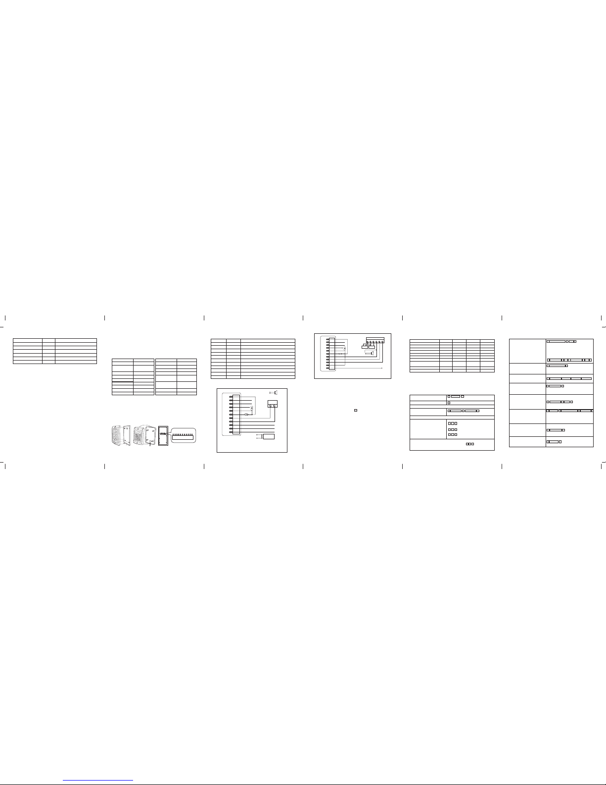
11 Inte rconn ectin g Two Devic es
11.1 W1/W 3-B ope ratin g as a Wieg and Out put Rea der
In this m ode th e W1/W 3-B su pport s a Wieg and 26 bit out put so the Wi egand data li nes
can be con necte d to any co ntrol ler whi ch supp orts a Wi egand 2 6 bit inp ut. See f igure 1 .
D0
D1
ALARM-
OPEN
D_IN
W1/W3-B
GND
AC&DC
AC&DC
NC
COM
NO
Controll er
V+
V+
GND
GND
D0
D1
Power
Green
White
Grey
Yellow
Brown
Red
Black
Blue
Purple
Orange
Pink
(With Wiegand 2 6 inPut )
Transmi ssion F ormat :
◆ 1: Keypa d Transm issio n
The Read er will t ransm it the PI N data wh en it rec eives t he last k ey (#) pr ess aft er
PIN code .
Format : Facil ity Cod e + PIN Cod e
(Facil ity cod e is any di gits be tween 0 ~255, f actor y defau lt is 0; Pi n code is a ny 1~4
digits b etwee n 0~999 9)
Exampl e: Faci lity co de: 1
PIN code : 5678
Press 56 78 #, the n the out put for mat wil l be: 001 05678
◆ 2: Proxi mity Ca rd Trans missi on
The Read er will t ransm it the ca rd data w hen it re ads the C ard.
Format : Card Nu mber (t he last 8 d igits o f Card Nu mber)
Remark s: No mat ter the c ard or pi n is vali d or inva lid, th e data wi ll be tra nsmit ted
11.2 W1/W 3-B ope ratin g as a Cont rolle r
In thi s mode the W1/W3 -B su pport s a W iegan d 26 bit i nput so an exte rnal Wiega nd
device with a 26 bit outpu t can be c onnec ted t o the Wieg and i nput termi nals on th e
W1/W3- B. Ei ther a n ID card reade r (12 5KHZ) or a n IC card reade r (13 .56MH Z) ca n
be conne cted to the W1/ W3-B. C ards a re requ ired t o be adde d at the e xtern al rea der,
except w here an e xtern al EM rea der is u sed, in t his cas e cards c an be ad ded at ei ther
reader o r contr oller. S ee figu re 2.
D0
D0
D1
D1
ALARM-
OPEN
D_IN
DC /3A12V
W1/W3-B
Door detecting switch
-
-
+
+
-
+
Special Po wer Sup ply
Alarm
GND
AC&DC
AC&DC
NC
COM
NO
NC CO M NO
+12V
GND
V+
GND
OPEN
Green
White
Grey
Yellow
Brown
Red
Black
Blue
Purple
Orange
Pink
Exit button
Wiegand r eader
Fail-Secure lock
Fail-Secure lock
1 User ID nu mber # PI N #
Add the ca rd as for a c ard use r
Press * to exit from the programming mode
Then all ocate t he card a P IN as fol lows:
* Read Car d 1234 # PI N # PIN #
W1-B W3-B
1. Pack ing lis t
Name
Digital K eypad W 1/W3- B
Quantit y
Remark
Screw dri ver
Rubber bu ngs
Self Tappin g Screw s
Manager C ard
1
4
4
2
6*27mm, u sed for f ixing
3.5*27m m, used f or fixi ng
Manager Ad d Card & Ma nager D elete C ard
User Manu al
1
1
Please e nsure t hat all t he abov e conte nts are c orrec t. If any a re miss ing ple ase not ify
the supp lier of t he W1/W 3-B.
2. Desc ripti on
3. Feat ures
l Waterp roof, c onfor ms to IP6 8
l Stron g Zinc All oy Elec tropl ated an ti-va ndal ca se
l Full pr ogram ming fr om the ke ypad
l 2500 us ers, su pport s Card, P IN, Car d + PIN
l Can be us ed as a sta nd alon e keypa d
l Progr ammab le one re lay out put
l Backl ight ke ypad
l Wiega nd 26 inp ut & outp ut
l Adjus table D oor Out put tim e, Alarm t ime, Do or Open t ime
l Block e nroll ment, c an enro ll maxi mum 250 0 conse cutiv e card wi thin 3 mi nutes
l Very low p ower co nsump tion (6 0Ma)
l Fast op erati ng spee d, <20m s with 25 00 user s
l Easy to i nstal l and pro gram
l Built i n light d epend ent res istor ( LDR) fo r anti ta mper
4. Spec ifica tions
12~24V AC/DC
2500
12 keys, 2 x 6 digits(W1-B)
12 keys, 3 x 4 digits(W3-B)
EM 125 KHZ car d/Tag
3~6 cm
<80mA
≤40mA
Max 2A
Max 20A
Operati ng Humi dity
Environ ment
Adjustable Door Relay time
Adjusta ble Alar m Time
Wiring Co nnect ions
Dimensi ons
Net Weigh t
Gross Wei ght
5%~ 95% RH
Conform s to IP68
0~99 seco nds
0~3 minut es
Electric Lock, Exit Button,
DOTL, External Alarm
550 g
700 g
Operati ng Volta ge
User Capa city
Keypad
Card Type
Card Reading Distance
Active Cu rrent
Idle Curr ent
Lock Outp ut Load
Alarm Out put Loa d
5. Inst allat ion
l Remov e the bac k cover f rom the k eypad u sing th e suppl ied sec urity s crewd river
l Drill 4 h oles on t he wall f or the sc rews an d I hole fo r the cab le
l Fix the b ack cov er firm ly on the w all wit h 4 flat he ad scre ws
l Threa d the cab le thro ugh the c able ho le
l Attac h the key pad to th e back co ver.
6. Wiri ng
Colour
Grey
Yellow
Brown
Red
Black
Blue
Purple
Functio n
D0
Alarm -
OPEN
D-IN
12~24V AC& DC
NO
COM
Descrip tion
Wiegand O utput D 0
White
Wiegand O utput D 1
Request t o Exit Bu tton
Door Cont act
12~24V Power Inp utAC&DC
12~24V AC& DC Powe r Input
Connec tion Di agram
8. Anti Ta mper Ala rm
The W 1/W3- B us es a LDR (li ght depe ndent res istor ) as an anti tam per alar m. I f th e
keypad i s remov ed from t he cove r then th e tampe r alarm w ill ope rate.
9. Sou nd and Li ght ind icatio n
Operati on Stat us
Power on
Operati on succ essfu l
Operati on fail ed
Enter int o progr ammin g mode
Red Light
Bright
-
-
-
Bright
Bright
Green Lig ht
-
-
-
Bright
-
-
Blue Ligh t
-
-
-
-
-
-
Buzzer
Short Rin g
-
Short Rin g
Short Rin g
3 Short Rin g
Short Rin g
-
Short Rin g
-
Press key pad
-
-
-
-
Bright
10. W1 /W3-B D etail ed Prog rammi ng Guide
10.1 Use r Setti ngs
To exit from t he prog rammi ng mode
To change th e maste r code
Set vali d card on ly user s
Set vali d card an d PIN use rs
Set vali d card or P IN user s
*
Master code
#
888888 i s the def ault fa ctory m aster c ode
To enter the p rogra mming m ode
*
Note tha t to unde rtake t he foll owing pr ogra mming t he mast er user mus t be log ged in
0 New code # N ew code #
The mast er code i s any 6 dig its.
To add a PIN use rs
1 User ID nu mber # PI N #
The ID numb er is any nu mber be tween 1 ~
2500. Th e PIN is a ny fou r digi ts betw een 00 00
~ 99 99 with t he excep tion of 1 234 whic h is
reserv ed. User s c an be adde d c ontin uousl y
withou t e xitin g f rom progra mming mode as
follow s:
1 User ID No 1 # PIN # User ID No 2 # PIN #
Operati ng Temper ature
-25~60℃
Alarm Neg ative
Orange
NC
Pink
GND
Stand by
Settin g the wor king mo de:
3 0 #
3 1 #
3 2 #
Entry is by either Card or PIN (default)
.2.
1
2
3
4
5
6
7
8
9
0
#
In the prog rammi ng mode
Exit from the programming mod e
Open the do or
.4.
.6.
.5.
To Delete a PI N user
To change th e PIN of a PI N user
(Note:Th is step m ust be do ne out of
programm ing mod e)
* ID number # Old PIN # New PIN # New PIN #
2 User ID nu mber #
Users c an be de leted con tinuo usly wit hout
exitin g progr ammin g mode
7. To Rese t to Fact ory Def ault
Bright
-
-
Bright
Alarm
.1.
To add a card us er (Met hod 1)
This is a fa st way to e nter ca rds
using ID n umber a uto gen erati on.
1 Read Car d #
Cards can be add ed continu ously wit hout exit ing
progra mming m ode
1 ID numbe r # Card #
To add a card us er (Met hod 2)
This is t he s eco nd w ay t o en ter
cards us ing Use r ID Alloc ation .
In this method a User ID is allocated
to a card. O nly one u ser ID ca n be
alloca ted to a si ngle ca rd.
l Built i n buzze r
l Red, Yell ow and Gr een LED s displ ay the wo rking s tatus
l 12~24 V AC/DC
l Two- yea r warra nty
W1/W3- B is sing le door m ultif uncti on acce ss cont rolle r or a Wieg and out put key pad or
card rea der. It is s uitab le for mo untin g eithe r indoo r or outd oor in ha rsh env ironm ents. I t
is house d in a stro ng, stu rdy and v andal p roof Zi nc Alloy e lectr oplat ed case .
The elec troni cs are fu lly pot ted so th e W1/W3 -B is wat erpro of and co nform s to IP68 .
The W1/W 3-B sup ports u p to 2500 u sers in e ither a C ard, 4 di git PIN , or a Card + P IN
option . The inbu ilt car d reade r suppo rts EM, 1 25KHZ f reque ncy car d/Tag. Th e W1/W3 B has many extra features includin g block enrollment,wieg and 26 bits interface, and backlit
keypad ...et c.
These fe ature s make th e W1/W3 -B an ide al choi ce for do or acce ss not on ly for sm all
shops an d domes tic hou sehol ds but al so for co mmerc ial and i ndust rial ap plica tions
such as fa ctori es, war ehous es, lab orato ries, b anks an d priso ns.
Wiegand I nterf ace
Wiegand 26 input & output
PCB conn ect dia gram
Anti-demolition alarm
D0
D1
ALARM-
OPEN
D_IN
GND
AC&DC
AC&DC
NC
COM
NO
J1
D0
D1
ALARM-
OPEN
D_IN
GND
AC&DC
AC&DC
NC
COM
NO
J1
Green
D1
12~24V AC& DC
Relay NO
Relay COM
Relay NC
W1/W3-B N egati ve
D0
D1
ALARM-
OPEN
D_IN
AC&DC
12~24V/3A
Exit button
W1/W3 -B
Door detecting swi tch
-
+
Green
White
Grey
Yellow
Brown
Red
Black
Blue
Purple
Orange
Power
Alarm
GND
AC&DC
AC&DC
NC
COM
NO
Pink
-
+
Lock
In4004
Power“+”
Electric bolt:NC
Electric strike :NO
Power“+”
Alarm “-”
Common P ower Su pply
D0
D1
ALARM-
OPEN
D_IN
DC /3A12V
W1/W3- B
-
+
Wiegand D0
Wiegand D1
GND
AC&DC
AC&DC
NC
COM
NO
NC COM NO
+12V
GNDOPEN
Green
White
Grey
Yellow
Brown
Red
Black
Blue
Purple
Orange
Pink
Door detecting switch
Exit button
Alarm
Power
+-+
-
Fail-secur e lock
Alarm“-”
Specia l Power S upply
Notes:
Connec t the neg ative p ole of th e lock to N C is for Fa il safe l ock.
Connec t the neg ative p ole of th e lock to N O is for Fa il-se cure lo ck.
To reset to f actor y de fault , pow er of f, pr ess * , h old i t and pow er on , rel ease it u ntil
hear two b eeps an d the LED s hines i n oran ge, the n read an y two EM ca rds, t he LED wi ll
turn i n re d, m eans rese t to fac tory defa ult setti ng s ucces sfull y. Of the two EM cards
read, the f irst on e is Mana ger Add car d, the se cond on e i s Manag er Dele te card .
---
-
Alarm
Bright
-
-
-
Short Rin g
Entry is by Card only
Entry is by Card and PIN together
To add and de lete us ers in ei ther ca rd or PIN m ode ( 3 2 # ) (Default se tting )
Card qua ntity i s betwe en 1~25 00.
The 8 digi ts card n umber i s the las t 8 digit s on
the card .
Maximum 2500 ca rds can b e enrol led at a st retch
within 3 mi nute s.
To add card us er (Met hod 3)
Add a seri es cards users
Block Enr ollment
To delete ca rd user b y card
number.
Note Use rs can be d elete d
contin uousl y witho ut exit ing
from pro gramm ing mod e.
2 Read Car d #
5 ID number # 8 digits Card number # Card quantity #
To dele te a car d us er b y us er I D.
This opti on can be us ed when a
user has l ost the ir card
2 User ID #
.3.
Remark s: Rese t to fact ory def ault, t he user 's info rmati on is sti ll reta ined.
( W1-B&W 3-B are i n the sam e funct ion, on ly diffe rent in s hape. )
L135 x W58 x H26 mm(W1-B)
L128 x W82 x H28 mm(W3-B)
W1-B W3-B
 Loading...